EP0784945A1 - Hook and eye fastener for clothing - Google Patents
Hook and eye fastener for clothing Download PDFInfo
- Publication number
- EP0784945A1 EP0784945A1 EP96120282A EP96120282A EP0784945A1 EP 0784945 A1 EP0784945 A1 EP 0784945A1 EP 96120282 A EP96120282 A EP 96120282A EP 96120282 A EP96120282 A EP 96120282A EP 0784945 A1 EP0784945 A1 EP 0784945A1
- Authority
- EP
- European Patent Office
- Prior art keywords
- clothes
- bar
- plate
- base plate
- hook
- Prior art date
- Legal status (The legal status is an assumption and is not a legal conclusion. Google has not performed a legal analysis and makes no representation as to the accuracy of the status listed.)
- Granted
Links
Images


Classifications
-
- A—HUMAN NECESSITIES
- A44—HABERDASHERY; JEWELLERY
- A44B—BUTTONS, PINS, BUCKLES, SLIDE FASTENERS, OR THE LIKE
- A44B13/00—Hook or eye fasteners
- A44B13/0005—Hook or eye fasteners characterised by their material
- A44B13/0023—Hook or eye fasteners characterised by their material made of plastics
-
- Y—GENERAL TAGGING OF NEW TECHNOLOGICAL DEVELOPMENTS; GENERAL TAGGING OF CROSS-SECTIONAL TECHNOLOGIES SPANNING OVER SEVERAL SECTIONS OF THE IPC; TECHNICAL SUBJECTS COVERED BY FORMER USPC CROSS-REFERENCE ART COLLECTIONS [XRACs] AND DIGESTS
- Y10—TECHNICAL SUBJECTS COVERED BY FORMER USPC
- Y10T—TECHNICAL SUBJECTS COVERED BY FORMER US CLASSIFICATION
- Y10T24/00—Buckles, buttons, clasps, etc.
- Y10T24/45—Separable-fastener or required component thereof [e.g., projection and cavity to complete interlock]
- Y10T24/45225—Separable-fastener or required component thereof [e.g., projection and cavity to complete interlock] including member having distinct formations and mating member selectively interlocking therewith
- Y10T24/4588—Means for mounting projection or cavity portion
- Y10T24/45942—Means for mounting projection or cavity portion having threaded formation
-
- Y—GENERAL TAGGING OF NEW TECHNOLOGICAL DEVELOPMENTS; GENERAL TAGGING OF CROSS-SECTIONAL TECHNOLOGIES SPANNING OVER SEVERAL SECTIONS OF THE IPC; TECHNICAL SUBJECTS COVERED BY FORMER USPC CROSS-REFERENCE ART COLLECTIONS [XRACs] AND DIGESTS
- Y10—TECHNICAL SUBJECTS COVERED BY FORMER USPC
- Y10T—TECHNICAL SUBJECTS COVERED BY FORMER US CLASSIFICATION
- Y10T24/00—Buckles, buttons, clasps, etc.
- Y10T24/45—Separable-fastener or required component thereof [e.g., projection and cavity to complete interlock]
- Y10T24/45225—Separable-fastener or required component thereof [e.g., projection and cavity to complete interlock] including member having distinct formations and mating member selectively interlocking therewith
- Y10T24/4588—Means for mounting projection or cavity portion
- Y10T24/45948—Means for mounting projection or cavity portion having specific structure for cooperating with stitching
-
- Y—GENERAL TAGGING OF NEW TECHNOLOGICAL DEVELOPMENTS; GENERAL TAGGING OF CROSS-SECTIONAL TECHNOLOGIES SPANNING OVER SEVERAL SECTIONS OF THE IPC; TECHNICAL SUBJECTS COVERED BY FORMER USPC CROSS-REFERENCE ART COLLECTIONS [XRACs] AND DIGESTS
- Y10—TECHNICAL SUBJECTS COVERED BY FORMER USPC
- Y10T—TECHNICAL SUBJECTS COVERED BY FORMER US CLASSIFICATION
- Y10T24/00—Buckles, buttons, clasps, etc.
- Y10T24/45—Separable-fastener or required component thereof [e.g., projection and cavity to complete interlock]
- Y10T24/45225—Separable-fastener or required component thereof [e.g., projection and cavity to complete interlock] including member having distinct formations and mating member selectively interlocking therewith
- Y10T24/45969—Hook-shaped projection member passing through cavity
- Y10T24/45974—Hook-shaped projection member passing through cavity formed from single piece of sheet metal
Landscapes
- Holders For Apparel And Elements Relating To Apparel (AREA)
Abstract
Description
- The present invention relates to a retaining device for clothes. More specifically, it relates to a structure of a retaining device for clothes formed of a plastic material.
- Retaining device for clothes have been widely used at upper end portions of mens' trousers, upper end portions of skirts and for lingeries. A structure of a retaining device for clothes used at an upper end portion of trousers will be described with reference to Fig. 32.
- A receiving member (straight bar eye, simply referred to as "bar") 120 formed of a metal material provided on one
end 200 of trousers forms an opening 120A together with theclothes 200. Meanwhile, an inserting member (hook) 110 formed of a metal material provided on theother end 100 of the trousers has abase portion 111 to be sewn on oneend 100 of the trousers, and aplate portion 112 to be inserted to the opening 120A formed by the receivingmember 120 and theother end 200 of the trousers. - By using the retaining device having the above described structure, one wears the trousers fit on the body by
inserting plate portion 112 ofhook 110 to opening 120A ofbar 120, as shown by the arrow of Fig. 32. - Now, recently, higher safety of products including clothes has been desired, as product liability act has been enforced. Accordingly, the clothes are inspected using a metal detector or the like to see if a needle or the like should be left in the clothes after garment manufacture.
- However, since the conventional retaining device for clothes is formed of metal, it causes unnecessary reaction of the metal detector.
- In view of the foregoing, recently, the surface of the retaining device for clothes is coated with a special coating so that the retaining device does not react to the metal detector. However, when the clothes are manufactured abroad and transported to domestic market by ship, for example, the coating and chemicals used for the clothes may possibly react, causing discoloring, as the clothes are kept sealed for a long period of time during transport by water.
- Therefore, an object of the present invention is to provide a retaining device for clothes formed of a plastic material which does not react to the metal detector, not susceptible to discoloring even when subjected to long transport by water and having characteristics sufficient for use and suitable for mass production. Another object of the present invention is to provide a retaining device for clothes having such a structure that allows easy and secure attachment on the clothes.
- According to one aspect, the present invention provides a retaining device for clothes attached to clothes or the like, and, for keeping the clothes fitted on one's body, including a receiving member attached to one end of the clothes and forming an opening together with the clothes and an inserting member attached to the other end of the clothes and inserted to the opening for engaging one and the other ends of the clothes, wherein the inserting member has a base plate formed of a plastic material and attached to the clothes; an inserting plate including a vertical portion extending in the vertical direction with respect to the base plate from one end of the base plate, a bent portion bent from the vertical portion to a direction parallel to said base plate, and a parallel portion extending parallel to the base plate from the bent portion, and forming, together with the base plate, a space for retaining the receiving member; a convex portion provided on an inner surface opposing to the base plate of the parallel portion of the inserting plate, serving as a stop in the direction of disengagement for the receiving member, to prevent the receiving member from slipping out of the space; and a rib provided projected outward on the outer surface of the inserting plate to suppress deflection of the inserting plate.
- By the above described structure, one and the other ends of the clothes can be engaged by inserting the inserting plate of the inserting member to an opening formed by the receiving member and the clothes.
- Further, since there is provided a convex portion on the inner surface of the parallel portion serving as a stop for the receiving member to the disengaging direction, the inserting member does not easily slip out from the opening. Further, since a rib is provided projecting outward from the outer surface of the inserting plate to suppress deflection of the inserting plate, elasticity of the inserting plate is improved, and hence it is possible to sufficiently secure the receiving member by the inserting plate.
- Accordingly, even if a plastic member is used, rigidity comparable to that of the retaining device for clothes formed of a metal member can be obtained by the retaining device for clothes having the above described structure.
- Further, as the retaining device for clothes is formed of a plastic material, it can be used in a stable state without any reaction with chemicals used for the clothes.
- Preferably, the rib is provided on the outer surfaces of the bent portion and the vertical portion of the inserting plate and, more preferably, on the outer surface of the parallel portion. More preferably, the rib is formed to have two protruding portions extending parallel to each other along the direction of extension of the inserting plate.
- By the provision of such a rib on the inserting plate, inserting plate can have sufficient elasticity and structural rigidity comparable to that of metal.
- Further, tip end side of the parallel portion of the inserting plate is made gradually narrower toward the tip end. Therefore, the inserting member can readily be inserted to the opening formed by the receiving member and the clothes.
- Preferably, the gap between the parallel portion of the inserting plate and the base plate is made larger than the thickness of the receiving member, and the gap between the convex portion and the base plate is made smaller than the thickness of the receiving member.
- Therefore, when the inserting plate is to be inserted to the opening formed by the receiving plate and the clothes, the inserting plate cannot be inserted to the opening unless it is once deflected outward at the portion where the convex portion is provided. Namely, once the inserting plate is inserted to the opening, the convex portion always abut the receiving member, and therefore disengagement of the inserting plate from the opening formed by the receiving member and the clothes can be prevented.
- Further, the thickness of the base plate is made approximately the same as the height of the opening formed by the receiving member and the clothes. As the rib is formed on the outer side of the inserting plate, when the inserting plate is inserted to the opening, the clothes is pressed by the rib.
- Therefore, as there is pressing force from the clothes to the inserting plate, strong engagement between the inserting member and the receiving member is ensured.
- Preferably, the receiving member is formed of a plastic material and has a protruding plate portion forming an opening with the clothes, and leg portions each having a hole for stitching the receiving member on the clothes provided at opposing ends of the plate portion. Preferably, the plate portion is formed protruding such that the height of the opening formed between the plate portion and the clothes is approximately the same as the thickness of the parallel portion of the inserting plate and that the width of the opening is approximately the same as the width of the inserting plate.
- Because of this structure, when the inserting plate is inserted to the opening formed between the plate portion and the clothes, the inserting plate does not rattle in the opening, and strong engagement between the inserting member and the receiving member in a stable state becomes possible.
- According to another aspect, the present invention provides a retaining device for clothes attached to a clothes or the like for keeping the clothes fit on one's body including a receiving member attached to one end of the clothes and forming an opening with the clothes, and an inserting member attached to the other end of the clothes and inserted to the opening for engaging one and the other ends of the clothes, wherein the inserting member includes a hook member to be inserted to the receiving member, and a hook washer member for fixing the hook member on the other end of the clothes.
- Further, the hook member is formed of a plastic material and includes: a base plate attached to the clothes; an inserting plate provided on that side of the base plate which does not face the clothes, including a vertical portion extending vertically with respect to the base plate, a bent portion bent toward the direction parallel to the base plate from the vertical portion, and a parallel portion extending parallel to the base plate from the bent portion, forming a space to retain the receiving member; a convex portion provided on an inner surface of the parallel portion of the inserting plate opposing to the clothes and serving as a stop for the receiving member to the disengaging direction for preventing the receiving member from slipping out from the aforementioned space; a rib protruding outward from the outer surface of the inserting plate to suppress deflection of the inserting plate; and a plurality of hook member legs formed on the surface of the base plate on the clothes side, which can stab the clothes.
- Further, the hook washer member includes a washer base formed of a plastic material and caulking holes for hook member legs provided in the washer base at positions corresponding to the hook member legs.
- When the retaining device for clothes having the above described structure is used, the hook member legs provided at the hook member stab the clothes, the hook member legs protruding from the clothes are fit in the hook washer member, and the hook member legs protruding from caulking holes for the hook member legs of the hook washer member are caulked, whereby the retaining device for clothes are readily and surely attached to the clothes.
- Further, preferably, the caulking hole for the hook member legs of the hook washer member is provided with a spot facing hole having larger diameter than the caulking hole on the surface not facing the clothes. Accordingly, the tip end portion of the caulked hook member leg is contained in the spot facing hole. Accordingly, the caulked portion of the hook member leg does not protrude from the hook washer member, which is desirable in view of design or appearance.
- Further, as for the receiving member also, the bar member legs of the bar member stab the clothes, the bar member legs protruding from the clothes are fitted in a bar washer member, and the bar member legs protruding from the caulking holes for the bar member legs are caulked, whereby the receiving member can readily and surely be fixed on the clothes.
- For the bar washer member also, by providing spot facing holes having larger diameter than the caulking hole on the surface of the caulking hole for bar member legs not facing the clothes, the tip end portions of the caulked bar member legs are contained in the spot facing holes. As a result, the caulked portions of the bar member legs do not protrude from the bar washer member, providing neat appearance/design.
- More preferably, a spacer for defining a space between the main bar and the clothes may be provided at a portion of the bar member legs connecting to the main bar, so that a prescribed space can surely and readily be provided between the bar member and the clothes.
- The foregoing and other objects, features, aspects and advantages of the present invention will become more apparent from the following detailed description of the present invention when taken in conjunction with the accompanying drawings.
- Fig. 1 is a schematic view showing the state of use of the retaining device for clothes in accordance with the first embodiment of the present invention.
- Fig. 2 is a perspective view showing the structure of the inserting member of the retaining device for clothes in accordance with the first embodiment of the present invention.
- Fig. 3 is a perspective view showing the structure of the receiving member of the retaining device for clothes in accordance with the first embodiment of the present invention.
- Fig. 4 is a vertical section showing dimensional relation of the retaining device for clothes in accordance with the first embodiment of the present invention.
- Fig. 5 is a cross section showing dimensional relation of the retaining device for clothes in accordance with the first embodiment of the present invention.
- Fig. 6 is a plan view of a hook member in accordance with a second embodiment of the present invention.
- Fig. 7 is a side view taken along the line A-A' of Fig. 6.
- Fig. 8 is a plan view of a hook washer member in accordance with the second embodiment of the present invention.
- Fig. 9 is a cross section taken along the line B-B' of Fig. 8.
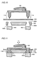
- Fig. 10 is a vertical section showing a first stage of attachment of the inserting member to the clothes in accordance with the second embodiment of the present invention.
- Fig. 11 is a vertical section showing a second stage of attachment of the inserting member to the clothes in accordance with the second embodiment of the present invention.
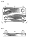
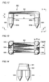
- Fig. 12 is a front view of a bar member in accordance with the second embodiment of the present invention.
- Fig. 13 is a bottom view taken along the line C-C' of Fig. 12.
- Fig. 14 is a side view taken along the line D-D' of Fig. 12.
- Fig. 15 is a plan view of a bar washer member in accordance with the present invention.
- Fig. 16 is a side view taken along the line E-E' of Fig. 15.
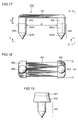
- Fig. 17 is a front view of the bar member in accordance with another embodiment of the present invention.
- Fig. 18 is a bottom view taken along the line F-F' of Fig. 17.
- Fig. 19 is a side view taken along the line G-G' of Fig. 17.
- Fig. 20 is a plan view of the bar washer member in accordance with another embodiment of the present invention.
- Fig. 21 is a side view taken along the line H-H' of Fig. 20.
- Fig. 22 is a vertical section showing a first stage of attachment of the receiving member to the clothes.
- Fig. 23 is a vertical section showing a second stage of attachment of the receiving member to the clothes.
- Fig. 24 is a plan view of a hook member in accordance with another embodiment of the present invention.
- Fig. 25 is a side view taken along the line I-I' of Fig. 24.
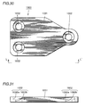
- Fig. 26 is a plan view of a hook washer member in accordance with another embodiment of the present invention.
- Fig. 27 is a side view taken along the line J-J' of Fig. 26.
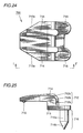
- Fig. 28 is a plan view of a hook member in accordance with a still further embodiment of the present invention.
- Fig. 29 is a side view taken along the line K-K' of Fig. 28.
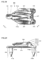
- Fig. 30 is a plan view of a hook member in accordance with a still further embodiment of the present invention.
- Fig. 31 is a side view taken along the line L-L' of Fig. 30.
- Fig. 32 is a schematic view showing the state of use of a conventional retaining device for clothes.
- The structure of the retaining device for clothes in accordance with the present invention will be described with reference to the drawings.
- Referring to Fig. 1, the state of use of the retaining device for clothes in accordance with the present invention will be described.
- Similar to the prior art, the retaining device for clothes in accordance with the present invention is used at upper end portion of trousers. On one
end 100 of the trousers, insertingmember 10 is sewn bysewing thread 30, and on theother end 200 of the trousers, the receivingmember 20 is sewn bysewing thread 30. - The inserting
plate 12 of insertingmember 10 is inserted to opening 20A formed by receivingmember 20 and oneend 200 of the trousers as represented by the arrow in the figure, whereby oneend 100 and theother end 200 of the trousers can be engaged. - Referring to Fig. 2, the structure of the inserting
member 10 will be described. The insertingmember 10 of the present invention is formed of a plastic material. - The inserting
member 10 has abase plate 11 which is attached to the clothes. At the tip end of thebase plate 11, there is asewing hole 11a for sewing the insertingmember 10 on the clothes, and there are a pair ofleg portions 16 on the sides ofbase plate 11 providingsewing holes 16a for sewing the insertingmember 10 on the clothes. - At a rear end of
base plate 11, there is formed an insertingplate 12 having avertical portion 12a extending vertically from the base plate, abent portion 12b bent to the direction parallel to thebase plate 11 fromvertical portion 12a, and aparallel portion 12c extending to the tip end parallel to thebase plate 11 from thebent portion 12b. The insertingplate 12 forms, together withbase plate 11, aspace 10A for receiving the receivingmember 20. - On an inner surface opposing the
base plate 11 of thehorizontal portion 12c of insertingplate 12, there is provided aconvex portion 15 which serves as a stop for the receivingmember 20 in the disengaging direction, so as to prevent slipping of the receivingmember 20 out from thespace 10A. - Further, on the outer surface of inserting
plate 12, there is provided arib 14 extending at least over thevertical portion 12a andbent portion 12b, so as to suppress deflection in the direction represented by the arrow T (in Fig. 2) of the insertingplate 12. In the present embodiment, as a most preferable example, arib 14 including two protruding portions extending parallel to each other extends along the direction of extension of the inserting plate on the outer surface of the inserting plate, coveringvertical portion 12a,bent portion 12b andhorizontal portion 12c. - Further, the tip end portion of
horizontal portion 12c has ataper 13a which becomes gradually narrower to the tip, facilitating insertion toopening 20A. - In the inserting
member 10 having the above described structure, sincerib 14 is provided extending at least along the outer peripheral surfaces ofvertical portion 12a andbent portion 12b, deflection of insertingplate 12 can be sufficiently suppressed, and hence rigidity and elasticity comparable to those of the conventional inserting member formed of a metal member can be obtained. - The structure of the receiving
member 20 of the present invention will be described with reference to Fig. 3. - The receiving
member 20 in accordance with the present invention is formed of the same plastic material as insertingmember 10, and it has a protrudingplate 21 forming, together with the clothes, anopening 21a, andleg portions 22 havingsewing holes 22a for sewing the receivingmember 20 on the clothes on opposing ends ofplate 21. - Referring to Figs. 4 and 5, dimensional relation between inserting
member 10 and receivingmember 20 will be described. - First, referring to Fig. 4, the space (h2) between
horizontal portion 12c of insertingplate 12 andbase plate 11 is larger than the thickness (h1) ofplate 21 of the receiving member, and space (h3) betweenconvex portion 15 andbase plate 11 is made smaller than the thickness (h1) of theplate 21 of the receivingmember 20. - Therefore, when
plate 21 is to be inserted tospace 10A, insertingplate 12 is deflected. Therefore, once the insertingplate 20 is inserted inspace 10A,convex portion 15 always serves as a stop for the plate in the disengaging direction, and hence engagement between insertingmember 10 and receivingmember 20 is ensured. - Next, referring to Fig. 5, the thickness of
horizontal portion 112c should preferably be made approximately the same as the height (h4) ofopening 21a formed by receivingmember 20 and the clothes. Since there isrib 14 on the outer surface ofhorizontal portion 112c, the clothes is pressed byrib 14, and there is always a force acting on horizontal portion 113 in the direction preventing slipping ofplate 21 from opening 10A. Therefore, insertingmember 10 and receivingmember 20 can be strongly engaged. - Further, the width of the
horizontal portion 12c should preferably be made approximately the same as the width (W3) ofopening 21a formed by receivingmember 20 and the clothes. - Accordingly, when
horizontal portion 12c is inserted to opening 21a,horizontal portion 12 is stably held inopening 21a, and hence insertingmember 10 and receivingmember 20 can be engaged strongly in more preferably state. - The structure of the retaining device for clothes in accordance with the second embodiment of the present invention will be described in the following.
- First, referring to Figs. 6 and 7, the structure of a
hook member 100 used for the retaining device for clothes in accordance with the present invention will be described. - Referring to these figures,
hook member 100 is formed of a plastic material.Hook member 100 has abase plate 111 attached to the clothes. On the surface not facing the clothes ofbase plate 11, there is formed an insertingplate 112 which has avertical portion 112a extending vertically frombase plate 11, abent portion 12b bent to a direction parallel to thebase plate 11 from avertical portion 12a, and aparallel portion 12c extending parallel tobase plate 11 from thebent portion 12b. Insertingplate 12 forms, together withbase plate 11, aspace 100A for receiving the receiving member (which will be described later). - On an inner surface opposing to
base plate 11 ofhorizontal portion 112c of insertingplate 12, there is provided aconvex portion 15 at such a position that presents a stop for the receiving member in the disengaging direction, for preventing the receiving member from slipping out fromspace 100A. - Further, on the outer surface of inserting
plate 112, there is formed arib 114 extending over at least thevertical portion 112a and thebent portion 112b. - In the present embodiment, as a most preferable example,
rib 114 including two protruding portions arranged parallel to each other along the direction of extension of insertingplate 112 is formed on the outer surface of insertingplate 112, extending over vertical portion 112A, bent portion 112B andhorizontal portion 112c. - Further, the tip end portion of
horizontal portion 112 has ataper 113a which becomes narrower toward the tip so as to facilitate insertion to the opening formed by the receiving member and the clothes. - Further, on the surface of base plate 113 facing the clothes, there are
hook member legs 116 at four corners ofbase plate 111.Hook member legs 116 each have abody 116a and pointedtip end 116b. - In the
hook member 100 having the above described structure,rib 114 is provided along at least the outer peripheral surfaces ofvertical portion 112a andbent portion 112b, so that deflection of insertingplate 112 is sufficiently suppressed, and hence rigidity and elasticity comparable to those of the conventional inserting member formed of a metal member can be obtained. - Referring to Figs. 8 and 9, the structure of
hook washer member 200 used as the inserting member will be described. -
Hook washer member 200 has ahook washer base 201 formed of a plastic material.Hook washer base 201 hascaulking holes 202 for hook member legs at positions corresponding to hookmember legs 116 provided onhook member 100. Caulking holes 202 for hook member each has a throughhole 202b and, on the side not facing the clothes, aspot facing hole 202a having larger diameter than the inner diameter of throughhole 202. - Attachment of the inserting member having the
hook member 100 and thehook washer member 200 having the above described structure to the clothes will be described with reference to Figs. 10 and 11. - Referring to Fig. 10,
hook member 100 is arranged aboveclothes 800, and ahook washer member 200 is placed below the clothes. At this time,hook washer member 200 is placed such that the spot facing hole 200a is positioned not facingclothes 800. - Then, a
jig 900 for caulkinghook member leg 116 is placed at a position opposing tocaulking holes 202 for hook member legs. Thejig 900 may be or may not be heated, provided that it can cause plastic deformation ofhook member legs 116. - Referring to Fig. 11, the
hook member leg 116 ofhook member 100 stabsclothes 800, andtip end portion 116b ofhook member leg 116 is caulked byjig 900. At this time, the caulkedtip end portion 116b is contained deformed inspot facing hole 202a. Therefore, the caulked portion ofhook member leg 116 does not protrude fromcaulking hole 202 for hook member leg, providing neat appearance. In this manner, the inserting member (hook) can readily and surely be attached to the clothes. - Referring to Figs. 12 to 14, the structure of the
bar member 300 used for the receiving member (bar) will be described. -
Bar member 300 is formed of a plastic material and has an approximately rectangularmain bar 301. At opposing ends ofmain bar 301, there are a total of fourbar member legs 303, two on each side, provided withspacer 302 interposed. Thebar member legs 303 each have abody 303a and pointedtip end 303b. - The height h of
spacer 302 is set to be approximately the same as the thickness ofparallel portion 112c of insertingplate 112, and the space W betweenspacer 302 on opposing ends is set to be approximately the same as the width ofparallel portion 112c of insertingplate 112. - Further, at least one of the widths W1 and W2 of
spacer 302 is set to be larger than the diameter ofbar member legs 303. - Accordingly, the clothes stabbed by
bar member leg 303 is brought into contact withspacer 302, and hence an opening to which insertingplate 112 is inserted can surely be formed betweenmain bar 301 and the clothes. - Referring to Figs. 15 and 16, the structure of
bar washer member 400 used for the receiving member (bar) will be described. -
Bar washer member 400 has abar washer base 401 formed of a plastic material.Bar washer base 401 hascaulking holes 402 for bar member legs at positions corresponding to thebar member leg 303 provided onbar member 300. Thecaulking hole 402 for bar member legs each have a throughhole 402b, and aspot facing hole 402 having larger diameter than the inner diameter of throughhole 402b on the side not facing to the clothes. - Though
bar member 300 andbar washer member 400 for four bar member legs have been described, the number of bar member legs may be two, as shown in Figs. 17 to 21. - The structure of
bar member 500 having two bar member legs will be briefly described with reference to Figs. 17 to 19. - This
bar member 500 is also formed of a plastic material similar tobar member 300, and has a rectangularmain bar 501. On opposing sides ofmain bar 501, a total of twobar member legs 503, one on each end, are provided withspacers 502 interposed. Thebar member legs 503 each have abody 503a and apointed tip end 503b. - The height h of
spacer 502 and the space W betweenspacers 502 on opposing ends are set in the similar manner asbar member 300. Further, the width W3 ofspacer 502 is made larger than the diameter ofbar member legs 503. - By such a structure also, similar function and effects as
bar member 300 can be obtained. - The structure of a
bar washer member 600 corresponding to barmember 500 will be described with reference to Figs. 20 and 21. - The
bar washer member 600 has abar washer base 601 formed of a plastic material, similar tobar washer member 400.Bar washer base 601 hascaulking holes 602 for bar member legs opened at positions corresponding to barmember legs 503 provided onbar member 500. -
Caulking hole 602 for bar member leg has a throughhole 602b, and aspot facing hole 602a having larger diameter than the inner diameter of throughhole 602b on the side not facing the clothes. - Attachment of receiving member (bar) having bar member 300 (500) and bar washer member 400 (600) having the above described structure to the clothes will be described with reference to Figs. 22 and 23.
- First, referring to Fig. 22, bar member 300 (500) is placed above
clothes 800, and bar washer member 400 (600) is placed below the clothes. At this time, the bar washer member 400 (600) is placed such that thespot facing holes 402a (602a) are positioned on the side not facing theclothes 800. - Then,
jig 900 for caulking bar member legs 303 (503) is arranged at a position opposing to hole 402 (602) for bar member leg. The jig may be or may not be heated provided that it causes plastic deformation of bar member leg 303 (503). - Referring to Fig. 23, bar member legs 303 (503) of bar member 300 (500) stab
clothes 800, and then tipend portions 303b (503b) of bar member legs 303 (503) are caulked byjig 900. At this time, the caulkedtip end portion 303b (503b) is deformed and contained withinspot facing hole 402a (602a). Therefore, the caulked portion of bar member leg 303 (503) does not protrude from bar washer member 400 (600), providing neat appearance. - In this manner, the receiving member (bar) can readily and surely be attached to the clothes.
- In the retaining device for clothes in accordance with the present embodiment,
hook member 100 andhook washer member 200 are used as inserting member (hook), andbar member 300 andbar washer member 400 are used as receiving member (bar). As thehook member legs 116 provided onhook member 100 andbar member leg 303 provided onbar member 300 stab the clothes andhook washer member 200 andbar washer member 400 are caulked, hook member andbar member 300 can surely be attached to the clothes. - The embodiments disclosed above are examples only and not limiting. For example, though inserting members having four hook member legs have been described with reference to Figs. 6 to 9, the number of hook member legs is not limited and any number of legs may be provided so long as the inserting member can surely be fixed on the clothes.
- Therefore, similar function and effects can be obtained when
hook member 700 having twohook member legs 716 and shown in Figs. 24 and 25 andhook washer member 800 shown in Figs. 26 and 27 are used. - Functions of
base plate 711, inserting plate 712 havingvertical portion 712a, bent portion 712b andhorizontal portion 712c,taper 713a,rib 714 and protrudingportion 715 ofhook member 700, and ofhook member legs 716 havingbodies 716a and tipend portions 716b are the same as those of the embodiment described above. Further, functions ofhook washer member 800 includinghook washer base 801 andcaulking holes 802 havingspot facing holes 802a and throughholes 802b are also the same as those of the embodiments described above. - Further, when hook member 90 having three
hook member legs 916 shown in Figs. 28 and 29 andhook washer member 1000 shown in Figs. 30 and 31 are used, similar functions and effects as the above described embodiments can be obtained. - The
hook member 900 shown in Figs. 28 and 29 is provided with a reinforcingrib 917 bridging betweenbent portion 912b andvertical portion 912a of insertingplate 912, between and in addition to the two ribs 194. Provision of the reinforcingrib 917 further improves elasticity of insertingplate 912. - Functions of
base plate 911, insertingplate 912 includingvertical portion 912a,bent portion 912b andhorizontal portion 912c,taper 913a,rib 914, convex portion 915 of insertingmember 900 and ofhook member legs 916 havingbodies 916a and tipend portions 916b are the same as those of the above described embodiments. Further, functions ofhook washer base 1001 andcaulking holes 1002 havingspot facing holes 1002a and throughholes 1002b are also the same as those of the above described embodiments. - Although the present invention has been described and illustrated in detail, it is clearly understood that the same is by way of illustration and example only and is not to be taken by way of limitation, the spirit and scope of the present invention being limited only by the terms of the appended claims.
Claims (10)
- A retaining device for clothes attached to clothes for keeping said clothes fit on one's body, including a receiving member (20) attached to one end (200) of said clothes and forming an opening (20A) together with said clothes, and inserting member (10) attached to the other end (100) of said clothes and engaging said one and the other ends (200, 100) of said clothes when inserted to said opening (20A), wherein
said inserting member (10) is formed of a plastic material and includesa base plate (11) attached to said clothes,an inserting plate (12) having a vertical portion (12a) extending vertically from said base plate (11) at one end of said base plate (11), a bent portion (12b) bent in a direction parallel to said base plate (11) from said vertical portion (12a), and a parallel portion (12c) extending parallel to said base plate (11) from said bent portion (12b), forming, together with said base plate (11), a space (10A) for receiving said receiving member (20),a convex portion (15) provided on an inner surface of said parallel portion (12c) of said inserting plate (12) opposing to said base plate (11), serving as a stop for said receiving member (20) in disengaging direction, for preventing said receiving member (20) from slipping out from said space (10A), anda rib (14) provided protruding outward on an outer surface of said inserting plate (12) to suppress deflection of said inserting plate (12). - The retaining device for clothes according to claim 1, wherein
said rib (14) is provided on outer surfaces of said vertical portion (12a) and said bent portion (12b) of said inserting plate (12) and/or
on an outer surface of said parallel portion (12c). - The retaining device for clothes according to claim 1 or 2, wherein
said rib (14) forms two protruding portions extending parallel to each other along direction of extension of said inserting plate (12) and/or
the tip end side of said parallel portion (12c) of said inserting plate (12) has a shape (13a) gradually becoming narrower toward the tip end, so as to facilitate insertion into said opening (20A) formed by said receiving member (20) and said clothes. - The retaining device for clothes according to one of claims 1 to 3, wherein
a gap (h2) between said parallel portion (12c) of said inserting plate (12) and said base plate (11) is larger than the thickness (h1) of said receiving member (20), and/or a gap (h3) between said convex portion (15) and said base plate (11) is smaller than the thickness (h1) of said receiving member (20) and/or
the thickness of said parallel portion (12c) of said inserting plate (12) is approximately the same as the height (h4) of the opening (20A) formed by said receiving member (20) and said clothes. - The retaining device for clothes according to one of claims 1 to 4, wherein
said base plate (11) has a sewing hole (11a) for attaching said inserting member (10) to said clothes at its tip end portion, and
a pair of legs (16) providing sewing holes (16a) for attaching the inserting member (11) to said clothes on side portions. - The retaining device for clothes according to one of claims 1 to 5, wherein
said receiving member (20) is formed of a plastic material, and it has
a protruding plate portion (21) for forming, when attached to the other end (200) of said clothes, an opening (21a) with said clothes, and
leg portions (22) provided at opposing ends of said plate portion (21) and having holes (22a) for sewing said receiving member on said clothes,
preferably said plate portion (21) is formed protruded such that the height (h4) of said opening (21a) formed between said plate portion (21) and said clothes is approximately the same as the thickness of said parallel portion (12c) of said inserting plate (12) and/or
said plate portion (21) is formed protruding such that the width of said opening (21a) formed between said plate portion (21) and said clothes is approximately the same as width of said parallel portion (12c) of said inserting plate (12). - A retaining device for clothes attached to clothes for keeping said clothes fitted on one's body, including a receiving member (300, 400) attached to one end of said clothes forming, together with said clothes, an opening, and an inserting member (100, 200) attached to the other end of said clothes for engaging said one end and said the other end of said clothes when inserted to said opening, wherein said inserting member (100, 200) has a hook member (100) to be inserted to said receiving member (300, 400), and a hook washer member (200) for fixing the hook member (100) at said the other end of said clothes,
said hook member (100) being formed of a plastic material and includinga base plate (111) attached to said clothes,an inserting plate (112) provided on a side of said base plate (111) not facing said clothes, and having a vertical portion (112a) extending vertically from said base plate (111), a bent portion (112b) bent to a direction parallel to said base plate (111) from the vertical portion (112a), anda parallel portion (112c) extending parallel to said base plate (111) from the bent portion (112b), forming a space for receiving said receiving member,a convex portion (115) provided on an inner surface of said parallel portion (112c) of said inserting plate (112) opposing to said clothes, serving as a stop for said receiving member (300, 400) in a disengaging direction, for preventing said receiving member (300, 400) from slipping out from said space,a rib (114) formed protruding outward on an outer surface of said inserting plate (112) for suppressing deflection of said inserting plate (112), anda plurality of hook member legs (116) formed on the surface of said base plate (111) facing said clothes which can stab said clothes,said hook washer member (200) includinga washer base (201) formed of a plastic material, and caulking holes (202) for hook member legs (116) provided on the washer base (201) at positions corresponding to said hook member legs (116). - The retaining device for clothes according to claim 7, wherein
said caulking holes (202) for hook member legs each have a spot facing hole (202a) of larger diameter than the caulking holes (202) on the side not facing said clothes. - The retaining device for clothes according to claim 7 or 8, wherein
said receiving member (300, 400) has a bar member (300) forming, together with said clothes, an opening, and a bar washer member (400) for fixing said bar member (300) on said one end of said clothes,
said bar member (300) being formed of a plastic material andincluding a main bar (300) received by a space formed by said inserting member (100, 200) and said clothes, anda plurality of bar member legs (303) provided on a surface of the main bar (300) facing said clothes, which can stab said clothes, andsaid bar washer member (400) including a bar washer base (401) formed of a plastic material, and caulking holes (402) for bar member legs (303) provided in the bar washer base (401) at positions corresponding to said bar member legs (303),said caulking holes (402) for bar member legs (303) each preferably having a spot facing hole (402a) of larger diameter than the caulking holes (402) on a surface not facing said clothes. - The retaining device for clothes according to one of claims 7 to 9, wherein
said bar member legs (303) include spacers (302) having wider width than diameter of said bar member legs (303) to define a space (h) between said main bar (300) and said clothes at a portion connecting to said main bar (300), thickness (W1) of said spacer (302) preferably being set to be approximately the same as thickness of said parallel portion of said inserting plate (112), and/or
said bar member legs (303) being provided on said main bar (300) such that width (W) of said opening formed between said main bar (300) and said clothes is approximately the same as width of said parallel portion (112c) of said inserting plate (112).
Applications Claiming Priority (6)
| Application Number | Priority Date | Filing Date | Title |
|---|---|---|---|
| JP12096 | 1996-01-22 | ||
| JP120/96 | 1996-01-22 | ||
| JP1996000120U JP3027079U (en) | 1996-01-22 | 1996-01-22 | Clothing closure |
| JP11375/96 | 1996-11-08 | ||
| JP1996011375U JP3040387U (en) | 1996-11-08 | 1996-11-08 | Clothing closure |
| JP1137596 | 1996-11-08 |
Publications (2)
| Publication Number | Publication Date |
|---|---|
| EP0784945A1 true EP0784945A1 (en) | 1997-07-23 |
| EP0784945B1 EP0784945B1 (en) | 1999-11-17 |
Family
ID=26333036
Family Applications (1)
| Application Number | Title | Priority Date | Filing Date |
|---|---|---|---|
| EP96120282A Expired - Lifetime EP0784945B1 (en) | 1996-01-22 | 1996-12-17 | Hook and eye fastener for clothing |
Country Status (4)
| Country | Link |
|---|---|
| US (1) | US5826313A (en) |
| EP (1) | EP0784945B1 (en) |
| CN (1) | CN1104212C (en) |
| DE (1) | DE69605176T2 (en) |
Cited By (2)
| Publication number | Priority date | Publication date | Assignee | Title |
|---|---|---|---|---|
| EP1129637A2 (en) * | 2000-03-01 | 2001-09-05 | Zanata S.p.A. | Hook |
| EP1129638A2 (en) * | 2000-03-01 | 2001-09-05 | Koji Kato | Hook assembly used for waist-adjusing mechanism of garment and garment having waist-adjusting mechanism |
Families Citing this family (6)
| Publication number | Priority date | Publication date | Assignee | Title |
|---|---|---|---|---|
| US6513209B1 (en) * | 2000-10-13 | 2003-02-04 | Nike, Inc. | Fastening system for a bra |
| DE102006010774A1 (en) * | 2005-12-22 | 2007-07-05 | Graf, Michaela, Adeje | Closure for connecting two pieces of material e.g. materials layers, has two partially spaced catch elements whereby first catch element has fixing material and second catch element has centric break |
| US20100248588A1 (en) * | 2009-03-30 | 2010-09-30 | Richard David Knittel | Releasing device for garment fasteners |
| SG10201913708XA (en) * | 2014-07-18 | 2020-03-30 | Fisher & Paykel Healthcare Ltd | Headgear clip arrangement |
| USD882066S1 (en) | 2016-05-13 | 2020-04-21 | Fisher & Paykel Healthcare Limited | Frame for a breathing mask |
| CN106742558B (en) * | 2016-12-16 | 2019-11-05 | 上海鸿润科技有限公司 | Container |
Citations (4)
| Publication number | Priority date | Publication date | Assignee | Title |
|---|---|---|---|---|
| FR390312A (en) * | 1908-05-16 | 1908-10-02 | Marie Sempe | Button clip |
| FR1541818A (en) * | 1967-01-28 | 1968-10-11 | Gutos Metallschliessen | Hook-and-eye closure for garment |
| US3426400A (en) * | 1966-12-29 | 1969-02-11 | Anthony Lauro | Plastic hook and eye fastener apparatus |
| US3892015A (en) * | 1974-06-17 | 1975-07-01 | Scovill Manufacturing Co | Waistband fastener |
Family Cites Families (7)
| Publication number | Priority date | Publication date | Assignee | Title |
|---|---|---|---|---|
| US573470A (en) * | 1896-12-22 | Garment-fastener | ||
| US581921A (en) * | 1897-05-04 | Hook and eye | ||
| US844486A (en) * | 1906-03-21 | 1907-02-19 | Joseph E Waterman | Garment-fastener. |
| US954458A (en) * | 1906-11-03 | 1910-04-12 | Clara B Patterson | Hook and eye. |
| US886241A (en) * | 1907-07-31 | 1908-04-28 | Enos Norton | Supporting device. |
| US1266219A (en) * | 1917-05-02 | 1918-05-14 | Richard S Curtiss | Garment-support. |
| DE3045169A1 (en) * | 1980-12-01 | 1982-06-03 | Gold- und Silber-Scheideanstalt Oberstein Franz Reischauer, 6580 Idar-Oberstein | CLOSURE FOR UPPER CLOTHING, ESPECIALLY FOR FUR CLOTHING |
-
1996
- 1996-12-17 DE DE69605176T patent/DE69605176T2/en not_active Expired - Lifetime
- 1996-12-17 EP EP96120282A patent/EP0784945B1/en not_active Expired - Lifetime
-
1997
- 1997-01-06 US US08/779,187 patent/US5826313A/en not_active Expired - Lifetime
- 1997-01-17 CN CN97102067.1A patent/CN1104212C/en not_active Expired - Fee Related
Patent Citations (4)
| Publication number | Priority date | Publication date | Assignee | Title |
|---|---|---|---|---|
| FR390312A (en) * | 1908-05-16 | 1908-10-02 | Marie Sempe | Button clip |
| US3426400A (en) * | 1966-12-29 | 1969-02-11 | Anthony Lauro | Plastic hook and eye fastener apparatus |
| FR1541818A (en) * | 1967-01-28 | 1968-10-11 | Gutos Metallschliessen | Hook-and-eye closure for garment |
| US3892015A (en) * | 1974-06-17 | 1975-07-01 | Scovill Manufacturing Co | Waistband fastener |
Cited By (4)
| Publication number | Priority date | Publication date | Assignee | Title |
|---|---|---|---|---|
| EP1129637A2 (en) * | 2000-03-01 | 2001-09-05 | Zanata S.p.A. | Hook |
| EP1129638A2 (en) * | 2000-03-01 | 2001-09-05 | Koji Kato | Hook assembly used for waist-adjusing mechanism of garment and garment having waist-adjusting mechanism |
| EP1129637A3 (en) * | 2000-03-01 | 2002-09-25 | Zanata S.p.A. | Hook |
| EP1129638A3 (en) * | 2000-03-01 | 2005-01-19 | Koji Kato | Hook assembly used for waist-adjusing mechanism of garment and garment having waist-adjusting mechanism |
Also Published As
| Publication number | Publication date |
|---|---|
| DE69605176T2 (en) | 2000-04-13 |
| EP0784945B1 (en) | 1999-11-17 |
| CN1161816A (en) | 1997-10-15 |
| CN1104212C (en) | 2003-04-02 |
| DE69605176D1 (en) | 1999-12-23 |
| US5826313A (en) | 1998-10-27 |
Similar Documents
| Publication | Publication Date | Title |
|---|---|---|
| EP0604161B1 (en) | Decorative pull tab | |
| CA2168182C (en) | Slider for slide fastener | |
| EP0784945B1 (en) | Hook and eye fastener for clothing | |
| EP1018609B1 (en) | Cord fastener | |
| CA1081487A (en) | Resilient depressible hook clasp for jewelry | |
| KR100438349B1 (en) | Buckle | |
| US5653002A (en) | Slide fastener | |
| US3765062A (en) | Fastening devices | |
| US5537725A (en) | Releasable catch for holding together two complementary parts of a flexible article | |
| US4054972A (en) | Brassiere fastener | |
| KR100288958B1 (en) | Removable Floor Stop Assembly for Slide Fasteners | |
| CA1315072C (en) | Eye for a hook-and-eye fastener | |
| CA1275165C (en) | Hook for a hook-and-eye fastener | |
| EP1306025A2 (en) | Belt connector | |
| EP1053693A2 (en) | Fastening device with tape | |
| JP3027079U (en) | Clothing closure | |
| KR850000879Y1 (en) | A fastener for garment | |
| US4288890A (en) | Hook for a hook-and-eye fastener | |
| JP3040387U (en) | Clothing closure | |
| KR920003046Y1 (en) | Rivet for garments | |
| EP1145659B1 (en) | Reversible press button garment closure | |
| JPH0357125Y2 (en) | ||
| EP0018387A1 (en) | Improvements relating to fasteners | |
| JPS6222240Y2 (en) | ||
| JP3068845U (en) | Tape-shaped snap |
Legal Events
| Date | Code | Title | Description |
|---|---|---|---|
| PUAI | Public reference made under article 153(3) epc to a published international application that has entered the european phase |
Free format text: ORIGINAL CODE: 0009012 |
|
| AK | Designated contracting states |
Kind code of ref document: A1 Designated state(s): DE FR GB IT |
|
| 17P | Request for examination filed |
Effective date: 19971224 |
|
| 17Q | First examination report despatched |
Effective date: 19980331 |
|
| GRAG | Despatch of communication of intention to grant |
Free format text: ORIGINAL CODE: EPIDOS AGRA |
|
| GRAG | Despatch of communication of intention to grant |
Free format text: ORIGINAL CODE: EPIDOS AGRA |
|
| GRAH | Despatch of communication of intention to grant a patent |
Free format text: ORIGINAL CODE: EPIDOS IGRA |
|
| GRAG | Despatch of communication of intention to grant |
Free format text: ORIGINAL CODE: EPIDOS AGRA |
|
| GRAH | Despatch of communication of intention to grant a patent |
Free format text: ORIGINAL CODE: EPIDOS IGRA |
|
| GRAA | (expected) grant |
Free format text: ORIGINAL CODE: 0009210 |
|
| AK | Designated contracting states |
Kind code of ref document: B1 Designated state(s): DE FR GB IT |
|
| REF | Corresponds to: |
Ref document number: 69605176 Country of ref document: DE Date of ref document: 19991223 |
|
| ET | Fr: translation filed | ||
| ITF | It: translation for a ep patent filed |
Owner name: MITTLER & C. S.R.L. |
|
| PLBE | No opposition filed within time limit |
Free format text: ORIGINAL CODE: 0009261 |
|
| STAA | Information on the status of an ep patent application or granted ep patent |
Free format text: STATUS: NO OPPOSITION FILED WITHIN TIME LIMIT |
|
| 26N | No opposition filed | ||
| REG | Reference to a national code |
Ref country code: GB Ref legal event code: IF02 |
|
| PGFP | Annual fee paid to national office [announced via postgrant information from national office to epo] |
Ref country code: GB Payment date: 20101221 Year of fee payment: 15 |
|
| PGFP | Annual fee paid to national office [announced via postgrant information from national office to epo] |
Ref country code: IT Payment date: 20101230 Year of fee payment: 15 |
|
| PGFP | Annual fee paid to national office [announced via postgrant information from national office to epo] |
Ref country code: FR Payment date: 20120103 Year of fee payment: 16 |
|
| PGFP | Annual fee paid to national office [announced via postgrant information from national office to epo] |
Ref country code: DE Payment date: 20111229 Year of fee payment: 16 |
|
| GBPC | Gb: european patent ceased through non-payment of renewal fee |
Effective date: 20121217 |
|
| REG | Reference to a national code |
Ref country code: FR Ref legal event code: ST Effective date: 20130830 |
|
| REG | Reference to a national code |
Ref country code: DE Ref legal event code: R119 Ref document number: 69605176 Country of ref document: DE Effective date: 20130702 |
|
| PG25 | Lapsed in a contracting state [announced via postgrant information from national office to epo] |
Ref country code: DE Free format text: LAPSE BECAUSE OF NON-PAYMENT OF DUE FEES Effective date: 20130702 |
|
| PG25 | Lapsed in a contracting state [announced via postgrant information from national office to epo] |
Ref country code: FR Free format text: LAPSE BECAUSE OF NON-PAYMENT OF DUE FEES Effective date: 20130102 Ref country code: GB Free format text: LAPSE BECAUSE OF NON-PAYMENT OF DUE FEES Effective date: 20121217 |
|
| PG25 | Lapsed in a contracting state [announced via postgrant information from national office to epo] |
Ref country code: IT Free format text: LAPSE BECAUSE OF NON-PAYMENT OF DUE FEES Effective date: 20121217 |