EP0784173A2 - Safety relief valve assembly for a fluid displacement apparatus - Google Patents
Safety relief valve assembly for a fluid displacement apparatus Download PDFInfo
- Publication number
- EP0784173A2 EP0784173A2 EP96308941A EP96308941A EP0784173A2 EP 0784173 A2 EP0784173 A2 EP 0784173A2 EP 96308941 A EP96308941 A EP 96308941A EP 96308941 A EP96308941 A EP 96308941A EP 0784173 A2 EP0784173 A2 EP 0784173A2
- Authority
- EP
- European Patent Office
- Prior art keywords
- valve
- assembly according
- valve mechanism
- relief
- valve body
- Prior art date
- Legal status (The legal status is an assumption and is not a legal conclusion. Google has not performed a legal analysis and makes no representation as to the accuracy of the status listed.)
- Granted
Links
Images


Classifications
-
- F—MECHANICAL ENGINEERING; LIGHTING; HEATING; WEAPONS; BLASTING
- F16—ENGINEERING ELEMENTS AND UNITS; GENERAL MEASURES FOR PRODUCING AND MAINTAINING EFFECTIVE FUNCTIONING OF MACHINES OR INSTALLATIONS; THERMAL INSULATION IN GENERAL
- F16K—VALVES; TAPS; COCKS; ACTUATING-FLOATS; DEVICES FOR VENTING OR AERATING
- F16K13/00—Other constructional types of cut-off apparatus; Arrangements for cutting-off
-
- F—MECHANICAL ENGINEERING; LIGHTING; HEATING; WEAPONS; BLASTING
- F16—ENGINEERING ELEMENTS AND UNITS; GENERAL MEASURES FOR PRODUCING AND MAINTAINING EFFECTIVE FUNCTIONING OF MACHINES OR INSTALLATIONS; THERMAL INSULATION IN GENERAL
- F16K—VALVES; TAPS; COCKS; ACTUATING-FLOATS; DEVICES FOR VENTING OR AERATING
- F16K27/00—Construction of housing; Use of materials therefor
- F16K27/12—Covers for housings
-
- F—MECHANICAL ENGINEERING; LIGHTING; HEATING; WEAPONS; BLASTING
- F16—ENGINEERING ELEMENTS AND UNITS; GENERAL MEASURES FOR PRODUCING AND MAINTAINING EFFECTIVE FUNCTIONING OF MACHINES OR INSTALLATIONS; THERMAL INSULATION IN GENERAL
- F16K—VALVES; TAPS; COCKS; ACTUATING-FLOATS; DEVICES FOR VENTING OR AERATING
- F16K17/00—Safety valves; Equalising valves, e.g. pressure relief valves
- F16K17/02—Safety valves; Equalising valves, e.g. pressure relief valves opening on surplus pressure on one side; closing on insufficient pressure on one side
- F16K17/04—Safety valves; Equalising valves, e.g. pressure relief valves opening on surplus pressure on one side; closing on insufficient pressure on one side spring-loaded
-
- F—MECHANICAL ENGINEERING; LIGHTING; HEATING; WEAPONS; BLASTING
- F16—ENGINEERING ELEMENTS AND UNITS; GENERAL MEASURES FOR PRODUCING AND MAINTAINING EFFECTIVE FUNCTIONING OF MACHINES OR INSTALLATIONS; THERMAL INSULATION IN GENERAL
- F16K—VALVES; TAPS; COCKS; ACTUATING-FLOATS; DEVICES FOR VENTING OR AERATING
- F16K47/00—Means in valves for absorbing fluid energy
-
- Y—GENERAL TAGGING OF NEW TECHNOLOGICAL DEVELOPMENTS; GENERAL TAGGING OF CROSS-SECTIONAL TECHNOLOGIES SPANNING OVER SEVERAL SECTIONS OF THE IPC; TECHNICAL SUBJECTS COVERED BY FORMER USPC CROSS-REFERENCE ART COLLECTIONS [XRACs] AND DIGESTS
- Y10—TECHNICAL SUBJECTS COVERED BY FORMER USPC
- Y10S—TECHNICAL SUBJECTS COVERED BY FORMER USPC CROSS-REFERENCE ART COLLECTIONS [XRACs] AND DIGESTS
- Y10S62/00—Refrigeration
- Y10S62/02—Refrigerant pumps
-
- Y—GENERAL TAGGING OF NEW TECHNOLOGICAL DEVELOPMENTS; GENERAL TAGGING OF CROSS-SECTIONAL TECHNOLOGIES SPANNING OVER SEVERAL SECTIONS OF THE IPC; TECHNICAL SUBJECTS COVERED BY FORMER USPC CROSS-REFERENCE ART COLLECTIONS [XRACs] AND DIGESTS
- Y10—TECHNICAL SUBJECTS COVERED BY FORMER USPC
- Y10T—TECHNICAL SUBJECTS COVERED BY FORMER US CLASSIFICATION
- Y10T137/00—Fluid handling
- Y10T137/7722—Line condition change responsive valves
- Y10T137/7837—Direct response valves [i.e., check valve type]
- Y10T137/7904—Reciprocating valves
- Y10T137/7922—Spring biased
- Y10T137/7929—Spring coaxial with valve
-
- Y—GENERAL TAGGING OF NEW TECHNOLOGICAL DEVELOPMENTS; GENERAL TAGGING OF CROSS-SECTIONAL TECHNOLOGIES SPANNING OVER SEVERAL SECTIONS OF THE IPC; TECHNICAL SUBJECTS COVERED BY FORMER USPC CROSS-REFERENCE ART COLLECTIONS [XRACs] AND DIGESTS
- Y10—TECHNICAL SUBJECTS COVERED BY FORMER USPC
- Y10T—TECHNICAL SUBJECTS COVERED BY FORMER US CLASSIFICATION
- Y10T137/00—Fluid handling
- Y10T137/8593—Systems
- Y10T137/87917—Flow path with serial valves and/or closures
- Y10T137/88054—Direct response normally closed valve limits direction of flow
Definitions
- the present invention relates to a safety relief valve assembly for a fluid displacement apparatus and, more particularly, to a safety relief valve assembly for a refrigerant compressor used in an automotive air conditioning system.
- Japanese Utility Publication No. H04-84976 discloses a safety relief valve device generally used in a refrigerant compressor for an automotive air conditioning system.
- the refrigerant compressor is provided with a safety relief valve device which automatically prevents excessive pressure build up in the compressor.
- the safety relief valve which is mounted on the compressor housing, opens and closes in response to the pressure in the compressor if the pressure in the compressor or the cooling circuit abnormally increases.
- refrigerant gas including lubricating oil is emitted in the engine compartment of the vehicle. If the emission strikes a high temperature component of the engine, such as an exhaust manifold, smoke along with offensive odors and sometimes even fire result.
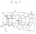
- relief valve assembly 10 includes valve mechanism 11 mounted on one end of a refrigerant compressor 100 and a cover member 18 attached to valve body 11a of valve mechanism 11.
- Valve mechanism 11 includes valve packing 15, valve member 14 surrounding valve packing 15, nut 13 disposed on the edge of valve body 11a, cap member 12 and spring 16 disposed between valve member 14 and cap member 12.
- Cap member 12 includes an opening 12a formed at the centre radial axis thereof Spring 16 biases valve member 14 and valve packing 15 toward the open end of passage 11b formed in the center of valve body 11a.
- Cover member 18 comprises a hexagonal plate portion 18a, a connecting portion 18b perpendicularly extending from one end of hexagonal plate portion 18b, arm portion 18c extending from connecting portion 18b and a ring portion 18d extending from one end of arm portion 18c. Cover member 18 is secured to valve mechanism 11 such that arm portion 18c and ring portion 18d respectively hold nut 13 and valve body 11a, and hexagonal plate portion 18a faces opening 12a of cap member 12.
- Cover member 18 is manufactured by blanking a plane plate and bending hexagonal plate portion 18a towards arm portion 18c at a 90° angle as shown in FIG. 3. Cover member 18 is provided with connecting portion 18b which eases the bending of hexagonal plate portion 18a. Gap G (FIG. 1) is created between hexagonal plate portion 18a and arm portion 18c.
- valve member 14 and valve packing 15 When the pressure in the cooling circuit and the compressor exceeds predetermined design pressures, the high pressure refrigerant gas causes valve member 14 and valve packing 15 to move away from the valve seat by overcoming the restoring force of coil spring 16. Refrigerant gas is then emitted in the direction of the longitudinal axis of valve body 11a through opening 12a of cap member 12. Thus, the refrigerant gas strikes and is directed along hexagonal plate portion 18a toward an area other than the high temperature components of the engine, for instance below compressor 100. When the pressure in the cooling circuit and the compressor decreases, valve member 14 and valve packing 15 return to the valve seat under the influence of the restoring force of coil spring 16.
- the relief valve releases excessive refrigerant gas from the refrigerant compressor when the pressure in the refrigerant compressor exceeds a predetermined level.
- the valve mechanism includes a valve body which has an inlet port connected to the housing of the refrigerant compressor. At least one relief port discharges excessive refrigerant gas therethrough.
- a projection portion extends from a periphery of the relief valve.
- a valve member is movably disposed in the valve body to open and close the relief port.
- a biasing means urges the valve member to close the relief port whenever the pressure in the valve body is below the predetermined safe pressure level.
- a control device is detachably mounted on the valve body and covers the relief port. The control device directs the flow of the excessive refrigerant gas toward a predetermined design direction.
- An elastic member is forcibly disposed between the valve body and the control device.
- the elastic member induces a groove facing the relief port of the valve body such that the groove and the valve body collectively form a passage for directing the excessive refrigerant gas.
- Safety relief valve assembly 30 connected to a refrigerant compressor 100 according to a first preferred embodiment of the present invention is shown.
- Safety relief valve assembly 30 comprises a valve mechanism connected to a relief port (not shown) of a compressor 100 and a cover member 22 fitted to valve mechanism 111.
- Valve mechanism 111 which is otherwise like valve mechansim; includes a first cylinder portion 111a formed in the center thereof, a first hexagonal refrigerant shaft 111b formed on one side of first cylinder portion 111a, a second hexagonal shaft 111c formed on the other side of first cylinder portion 111a, and a second cylinder portion 111d extending from second hexagonal shaft 111c.
- Valve mechanism 111 further includes a passage 112 formed through the center longitudinal axis thereof. Passage 112 extends from first hexagonal shaft 111b to the end of the second cylindrical portion 111d. Valve mechanism 111 is secured to one end surface of compressor 100. The center axis X of valve mechanism 111 is perpendicular to the surface of compressor 100.
- cover member 22 includes a hexagonal plate 22a, three arm plates 22b perpendicularly extending from alternate edges of hexagonal plate 22a and a pair of plates 22c perpendicularly extending from two of the remaining edge of hexagonal plate 22a.
- Each arm plate 22b comprises a pair of first nail portions 22d and a pair of second nail portions 22e formed at the center of each arm plate 22b.
- Cover member 22 is produced by blanking a plane plate, which is preferably made of steel or resin, and bending three arm plates 22b and plates 22c 90° along the edges of hexagonal plate 22a.
- First nail portions 22d and second nail portions 22e are produced by making a slit S in the center of each arm plate 22b and by bending nail portions 22d, 22e to arm plate 22b at an angle smaller than 45°.
- cover member 22 is secured to valve mechanism 111 such that first and second nail portions 22d, 22e respectively engage second hexagonal shaft 111c.
- hexagonal elastic member 23 which is preferably made of soft resin or rubber, is compressively inserted between second cylindrical portion 111d and cover member 22 to face passage 112.
- Hexagonal elastic member 23 includes a groove 24 formed at one end surface thereof. Groove 24 extends from position 24a near one edge thereof to opposite side edge 24b. Hexagonal elastic member 23 includes sloped bottom portion 24c whose depth increases with distance from position 24a. Groove 24 and the end surface of first hexagonal shaft 111b collectively form a passageway 25 through which excessively pressurized gas is discharged.
- safety relief valve assembly 30 In operation, when the pressure in the cooling circuit (not shown) and compressor 100 increase and exceeds a predetermined pressure level, safety relief valve assembly 30 operates to reduce the pressure.
- the high pressure fluid gas discharged from compressor 100 through passage 112 blows toward a specified design direction as a result of being directed through passageway 25.
- substantially all of the excessive gas which includes lubricating oil discharged from compressor 100, may be directed away from the hot components in the vehicle engine compartment, since groove 24 of hexagonal elastic member 23 seals the gaps created between arm plates 22b and plate 22c.
- the high pressure gas more smoothly flows through passageway 25 in comparison with relief valve assembly 10 of the embodiment of FIG. 1 since the bottom portion 24c of groove 24 is tapered.
- the direction of the gas emitted from valve mechanism 111 can be selectively changed since first and second nail portions 22d, 22e detachably take hold of a radial end of second hexagonal shaft 111c.
- FIGS. 8-10 illustrate second through fourth embodiments of the present invention.
- the safety relief valve assemblies of these additional embodiments are generally similar to the safety relief valve assembly 30 described above. However, some difference do exist as follows.
- labyrinth packing 26, which is made of rubber, or soft resin is disposed on the side edge of groove 24 (shown in FIG. 8) in order to shade passageway 25.
- a cantilever plate 28 which hingedly opens passage 25 if excessively pressurized gas is emitted and closes the same after the gas has been emitted, is disposed on the side edge of groove 24 (shown in FIG. 9) in order to shade passageway 25.
- High pressure gas discharged from compressor 100 through passage 112 of valve body 111 is directed to the engine compartment through labyrinth 26, or after breaking thin plate 27, or after opening cantilever plate 28.
- labyrinth 26, thin plate 27 and cantilever plate 28 prevent debris from obstructing passageway 25.
- FIG. 11 illustrates a fifth preferred embodiment of the present invention.
- the safety relief valve assembly is generally similar to the safety relief valve assembly described above. However, some difference do exists as follows.
- Valve mechanism 211 includes a cylinder portion 211a formed at the center thereof, a first hexagonal shaft 211b formed at one end of cylinder portion 211a and a second hexagonal shaft 211c formed the other end of cylinder portion 211a.
- Valve mechanism 211 includes a plurality of holes 211d annularly formed on the periphery of cylinder portion 211a at equal intervals. Holes 211d communicate with passage 212 formed along the center axis of valve mechanism 211.
- Cylinder portion 211a includes a pair of annular grooves 211e on either side of holes 211d.
- Cover member 29 includes a ring portion 29a and preferably includes a pair of flanges 29b extending from both ends of ring portion 29a. Cover member 29 is fitted on valve mechanism 211. More specifically, ring portion 29a is mounted on cylinder portion 211a and shades holes 211d. A gap C is formed between flanges 29b. At least one hole 211d is exposed between flanges 29b. Substantially the same advantages are obtained as in the first preferred embodiment. Furthermore, the fifth embodiment allows the direction of the high pressure gas discharged from compressor 200 to be selectively altered since the position of gap C can be changed by rotating ring portion 29a around cylindrical portion 211a.
Abstract
Description
- The present invention relates to a safety relief valve assembly for a fluid displacement apparatus and, more particularly, to a safety relief valve assembly for a refrigerant compressor used in an automotive air conditioning system.
- Many safety relief valves for refrigerant compressor applications are well known in the prior art. For example, Japanese Utility Publication No. H04-84976 discloses a safety relief valve device generally used in a refrigerant compressor for an automotive air conditioning system. The refrigerant compressor is provided with a safety relief valve device which automatically prevents excessive pressure build up in the compressor. The safety relief valve, which is mounted on the compressor housing, opens and closes in response to the pressure in the compressor if the pressure in the compressor or the cooling circuit abnormally increases.
- When the safety relief valve operates, refrigerant gas including lubricating oil is emitted in the engine compartment of the vehicle. If the emission strikes a high temperature component of the engine, such as an exhaust manifold, smoke along with offensive odors and sometimes even fire result.
- One attempt to resolve this problem was derived by us. Though not prior art, this attempt is indicative of the prior shortcomings of earlier solutions. Referring to FIGS. 1-3,
relief valve assembly 10 includesvalve mechanism 11 mounted on one end of arefrigerant compressor 100 and acover member 18 attached tovalve body 11a ofvalve mechanism 11.Valve mechanism 11 includesvalve packing 15,valve member 14 surroundingvalve packing 15,nut 13 disposed on the edge ofvalve body 11a,cap member 12 andspring 16 disposed betweenvalve member 14 andcap member 12.Cap member 12 includes an opening 12a formed at the centre radial axis thereofSpring 16biases valve member 14 and valve packing 15 toward the open end of passage 11b formed in the center ofvalve body 11a. -
Cover member 18 comprises a hexagonal plate portion 18a, a connecting portion 18b perpendicularly extending from one end of hexagonal plate portion 18b, arm portion 18c extending from connecting portion 18b and aring portion 18d extending from one end of arm portion 18c.Cover member 18 is secured tovalve mechanism 11 such that arm portion 18c andring portion 18d respectively holdnut 13 andvalve body 11a, and hexagonal plate portion 18a faces opening 12a ofcap member 12. -
Cover member 18 is manufactured by blanking a plane plate and bending hexagonal plate portion 18a towards arm portion 18c at a 90° angle as shown in FIG. 3.Cover member 18 is provided with connecting portion 18b which eases the bending of hexagonal plate portion 18a. Gap G (FIG. 1) is created between hexagonal plate portion 18a and arm portion 18c. - When the pressure in the cooling circuit and the compressor exceeds predetermined design pressures, the high pressure refrigerant gas causes
valve member 14 and valve packing 15 to move away from the valve seat by overcoming the restoring force ofcoil spring 16. Refrigerant gas is then emitted in the direction of the longitudinal axis ofvalve body 11a through opening 12a ofcap member 12. Thus, the refrigerant gas strikes and is directed along hexagonal plate portion 18a toward an area other than the high temperature components of the engine, for instance belowcompressor 100. When the pressure in the cooling circuit and the compressor decreases,valve member 14 and valve packing 15 return to the valve seat under the influence of the restoring force ofcoil spring 16. - Even in this configuration, however, it has been experienced that some of the refrigerant gas comes into contact with the high temperature components of the engine due to the presence of gap G. Thus, the problem has not been totally solved, and there remains the possibility of causing smoke or an offensive odor or even fire from the engine compartment of the vehicle.
- It is an object of the present invention to provide a safety relief valve assembly for use in a refrigerant compressor of an automotive air conditioning system wherein the refrigerant gas emitted from the relief valve assembly is directed in a predetermined direction without coming into contact with the high temperature components of the engine.
- According to the present invention, a safety relief valve assembly for use in a refrigerant compressor comprises a valve mechanism which is connected to the compressor housing. The relief valve releases excessive refrigerant gas from the refrigerant compressor when the pressure in the refrigerant compressor exceeds a predetermined level. The valve mechanism includes a valve body which has an inlet port connected to the housing of the refrigerant compressor. At least one relief port discharges excessive refrigerant gas therethrough. A projection portion extends from a periphery of the relief valve. A valve member is movably disposed in the valve body to open and close the relief port. A biasing means urges the valve member to close the relief port whenever the pressure in the valve body is below the predetermined safe pressure level. A control device is detachably mounted on the valve body and covers the relief port. The control device directs the flow of the excessive refrigerant gas toward a predetermined design direction.
- An elastic member is forcibly disposed between the valve body and the control device. The elastic member induces a groove facing the relief port of the valve body such that the groove and the valve body collectively form a passage for directing the excessive refrigerant gas.
- In the accompanying drawings:
- FIG. 1 is a perspective view of a safety relief valve assembly connected to a fluid displacemen apparatus
- FIG. 2 is an enlarged sectional view of a valve body of the safety relief valve assembly of FIG. 1.
- FIG. 3 shows a blank for a cover member of the safety relief valve assembly of FIG. 1.
- FIG. 4 is a perspective view of a safety relied valve assembly connected to a fluid displacement apparatus in accordance with a first preferred embodiment of the present invention.
- FIG. 5 is an enlarged sectional view of the safety relief valve assembly of FIG. 4.
- FIG. 6 shows a blank for a cover member of the safety relief valve assembly of FIG. 4.
- FIG. 7 is a perspective view of an elastic member of the safety relief valve assembly of FIG. 4.
- FIG. 8 is an enlarged sectional view of an elastic member of the safety relief valve assembly in accordance with a second preferred embodiment of the present invention.
- FIG. 9 is an enlarged sectional view of an elastic member of the safety relief valve assembly in accordance with a third preferred embodiment of the present invention.
- FIG. 10 is an enlarged sectional view of an elastic member of the safety relief valve assembly in accordance with a fourth preferred embodiment of the present invention.
- FIG. 11 is a perspective view of a safety relief valve assembly connected to a fluid displacement apparatus in accordance with a fifth preferred embodiment of the present invention.
- FIG. 12 is an enlarged sectional view of the safety relief valve assembly in accordance with FIG. 11.
- With reference to FIGS. 4 and 5, a safety
relief valve assembly 30 connected to arefrigerant compressor 100 according to a first preferred embodiment of the present invention is shown. Safetyrelief valve assembly 30 comprises a valve mechanism connected to a relief port (not shown) of acompressor 100 and acover member 22 fitted tovalve mechanism 111.Valve mechanism 111, which is otherwise like valve mechansim; includes afirst cylinder portion 111a formed in the center thereof, a first hexagonal refrigerant shaft 111b formed on one side offirst cylinder portion 111a, a secondhexagonal shaft 111c formed on the other side offirst cylinder portion 111a, and a second cylinder portion 111d extending from secondhexagonal shaft 111c.Valve mechanism 111 further includes apassage 112 formed through the center longitudinal axis thereof.Passage 112 extends from first hexagonal shaft 111b to the end of the second cylindrical portion 111d.Valve mechanism 111 is secured to one end surface ofcompressor 100. The center axis X ofvalve mechanism 111 is perpendicular to the surface ofcompressor 100. - With reference to FIG. 6 in conjunction with FIGS. 4 and 5,
cover member 22 includes ahexagonal plate 22a, three arm plates 22b perpendicularly extending from alternate edges ofhexagonal plate 22a and a pair ofplates 22c perpendicularly extending from two of the remaining edge ofhexagonal plate 22a. Each arm plate 22b comprises a pair offirst nail portions 22d and a pair ofsecond nail portions 22e formed at the center of each arm plate 22b.Cover member 22 is produced by blanking a plane plate, which is preferably made of steel or resin, and bending three arm plates 22b andplates 22c 90° along the edges ofhexagonal plate 22a.First nail portions 22d andsecond nail portions 22e are produced by making a slit S in the center of each arm plate 22b and by bendingnail portions cover member 22 is secured tovalve mechanism 111 such that first andsecond nail portions hexagonal shaft 111c. - Referring to FIG. 7, hexagonal
elastic member 23, which is preferably made of soft resin or rubber, is compressively inserted between second cylindrical portion 111d andcover member 22 toface passage 112. Hexagonalelastic member 23 includes agroove 24 formed at one end surface thereof. Groove 24 extends fromposition 24a near one edge thereof to opposite side edge 24b. Hexagonalelastic member 23 includes slopedbottom portion 24c whose depth increases with distance fromposition 24a.Groove 24 and the end surface of first hexagonal shaft 111b collectively form apassageway 25 through which excessively pressurized gas is discharged. - In operation, when the pressure in the cooling circuit (not shown) and
compressor 100 increase and exceeds a predetermined pressure level, safetyrelief valve assembly 30 operates to reduce the pressure. The high pressure fluid gas discharged fromcompressor 100 throughpassage 112 blows toward a specified design direction as a result of being directed throughpassageway 25. - Accordingly, substantially all of the excessive gas, which includes lubricating oil discharged from
compressor 100, may be directed away from the hot components in the vehicle engine compartment, sincegroove 24 of hexagonalelastic member 23 seals the gaps created between arm plates 22b andplate 22c. Further, the high pressure gas more smoothly flows throughpassageway 25 in comparison withrelief valve assembly 10 of the embodiment of FIG. 1 since thebottom portion 24c ofgroove 24 is tapered. Furthermore, the direction of the gas emitted fromvalve mechanism 111 can be selectively changed since first andsecond nail portions hexagonal shaft 111c. - FIGS. 8-10 illustrate second through fourth embodiments of the present invention. The safety relief valve assemblies of these additional embodiments are generally similar to the safety
relief valve assembly 30 described above. However, some difference do exist as follows. In one alternative embodiment, labyrinth packing 26, which is made of rubber, or soft resin, is disposed on the side edge of groove 24 (shown in FIG. 8) in order to shadepassageway 25. Alternatively, athin plate 27, which is made of rubber or soft resin and designed to break if gas is emitted, is disposed on the side edge of groove 24 (shown in FIG. 9) in order to shadepassageway 25. In another alternative embodiment, acantilever plate 28, which hingedly openspassage 25 if excessively pressurized gas is emitted and closes the same after the gas has been emitted, is disposed on the side edge of groove 24 (shown in FIG. 9) in order to shadepassageway 25. High pressure gas discharged fromcompressor 100 throughpassage 112 ofvalve body 111 is directed to the engine compartment throughlabyrinth 26, or after breakingthin plate 27, or after openingcantilever plate 28. - The advantages realized by the embodiments of FIGS. 8-10 are substantially similar to those obtained in the first embodiment. Furthermore,
labyrinth 26,thin plate 27 andcantilever plate 28 prevent debris from obstructingpassageway 25. - FIG. 11 illustrates a fifth preferred embodiment of the present invention. The safety relief valve assembly is generally similar to the safety relief valve assembly described above. However, some difference do exists as follows.
Valve mechanism 211 includes acylinder portion 211a formed at the center thereof, a firsthexagonal shaft 211b formed at one end ofcylinder portion 211a and a secondhexagonal shaft 211c formed the other end ofcylinder portion 211a.Valve mechanism 211 includes a plurality ofholes 211d annularly formed on the periphery ofcylinder portion 211a at equal intervals.Holes 211d communicate withpassage 212 formed along the center axis ofvalve mechanism 211.Cylinder portion 211a includes a pair ofannular grooves 211e on either side ofholes 211d.Cover member 29 includes aring portion 29a and preferably includes a pair of flanges 29b extending from both ends ofring portion 29a.Cover member 29 is fitted onvalve mechanism 211. More specifically,ring portion 29a is mounted oncylinder portion 211a and shadesholes 211d. A gap C is formed between flanges 29b. At least onehole 211d is exposed between flanges 29b. Substantially the same advantages are obtained as in the first preferred embodiment. Furthermore, the fifth embodiment allows the direction of the high pressure gas discharged from compressor 200 to be selectively altered since the position of gap C can be changed by rotatingring portion 29a aroundcylindrical portion 211a.
Claims (15)
- A safety relief valve assembly for use in a fluid displacement apparatus having a housing, the assembly comprising a valve mechanism, including at least one relief port connected, in use, to the housing, for releasing gases from the fluid displacement apparatus when the pressure in the fluid displacement apparatus exceeds a predetermined pressure level; and a control means detachably mounted on the valve mechanism so as to surround the relief port for directing the flow of the gas from the relief port in a predetermined direction.
- An assembly according to claim 1, further comprising an elastic member compressed between the valve mechanism and the control means, and having a groove facing an end of and extending radially of, the relief port, the groove and the valve mechanism collectively forming a passage for directing the gas.
- An assembly according to claim 2, wherein the groove has a depth which increases with radial distance from the relief port.
- An assembly according to claim 2 or claim 3, wherein the elastic member includes a labyrinth packing disposed at an outer end of the groove for shielding the passage.
- An assembly according to claim 2 or claim 3, wherein the elastic member includes a thin plate member disposed at an outer end of the groove for shielding the passage.
- An assembly according to claim 2 or claim 3, wherein the elastic member includes a cantilever plate member disposed at an outer end of the groove for shielding the passage.
- An assembly according to any one of the preceding claims, wherein the control means comprising a plate member facing the relief port and having a plurality of arms extending from edges of the plate member, the arms releasably engaging the valve mechanism.
- An assembly according to claim 1, wherein the control means includes a C-shaped ring portion for engaging the valve mechanism and a pair of flanges extending from open ends of the C-shaped ring portion.
- An assembly according to any one of the preceding claims, wherein the valve mechanism includes a valve body having an inlet port connected, in use, to the housing and the relief port for discharging excessive refrigerant gas pressure, a valve member movable in the valve body to open and close the relief port, and biasing means for moving the valve member to close the relief port whenever the pressure in the valve body is below the predetermined pressure level.
- An assembly according to claim 1, wherein the valve mechanism includes a valve body having an inlet port connected, in use, to the housing, a plurality of relief ports formed along the periphery of the valve body for discharging excessive refrigerant gas pressure, a valve member movable in the valve body to open and close the relief port, and biasing means for moving the valve member to close the relief port when the pressure in the valve body is below the predetermined pressure level; and the control means being arranged to cover a plurality of the relief ports, for directing the flow of gas in a predetermined direction by leaving open at least one of the relief ports.
- An assembly according to claim 10, wherein the control means includes a C-shaped ring member engaging the valve body.
- An assembly according to claim 11, wherein the C-shaped ring member includes a pair of flanges extending from the open ends thereof.
- An assembly according to any one of claims 10 to 13, wherein a plurality of the relief ports are peripherally formed around the valve body at equiangular intervals.
- An assembly according to any one of the preceding claims, wherein the predetermined direction is a selected one of a plurality of available directions.
- A refrigerant compressor for an automobile air conditioning system, the compressor having a housing fitted with a safety relief valve assembly according to any one of the preceding claims.
Applications Claiming Priority (3)
| Application Number | Priority Date | Filing Date | Title |
|---|---|---|---|
| JP346646/95 | 1995-12-13 | ||
| JP34664695 | 1995-12-13 | ||
| JP7346646A JP3038681B2 (en) | 1995-12-13 | 1995-12-13 | Compressor safety valve |
Publications (3)
| Publication Number | Publication Date |
|---|---|
| EP0784173A2 true EP0784173A2 (en) | 1997-07-16 |
| EP0784173A3 EP0784173A3 (en) | 1998-03-25 |
| EP0784173B1 EP0784173B1 (en) | 2000-06-07 |
Family
ID=18384860
Family Applications (1)
| Application Number | Title | Priority Date | Filing Date |
|---|---|---|---|
| EP96308941A Expired - Lifetime EP0784173B1 (en) | 1995-12-13 | 1996-12-10 | Safety relief valve assembly for a fluid displacement apparatus |
Country Status (6)
| Country | Link |
|---|---|
| US (2) | US5794915A (en) |
| EP (1) | EP0784173B1 (en) |
| JP (1) | JP3038681B2 (en) |
| KR (1) | KR100454778B1 (en) |
| AU (1) | AU703663B2 (en) |
| DE (1) | DE69608777T2 (en) |
Cited By (3)
| Publication number | Priority date | Publication date | Assignee | Title |
|---|---|---|---|---|
| CN102734135A (en) * | 2011-03-31 | 2012-10-17 | 株式会社丰田自动织机 | Relief valve for compressor |
| EP2470816A4 (en) * | 2009-08-25 | 2015-05-27 | Carrier Corp | Method and apparatus to indicate activation of pressure relief device |
| EP3205912A4 (en) * | 2014-12-04 | 2017-10-11 | Pacific Industrial Co., Ltd. | Relief valve |
Families Citing this family (27)
| Publication number | Priority date | Publication date | Assignee | Title |
|---|---|---|---|---|
| JP3038681B2 (en) * | 1995-12-13 | 2000-05-08 | サンデン株式会社 | Compressor safety valve |
| GB2314789A (en) * | 1996-07-03 | 1998-01-14 | Convac Limited | Non-return valve for a dust bag |
| US5984645A (en) * | 1998-04-08 | 1999-11-16 | General Motors Corporation | Compressor with combined pressure sensor and high pressure relief valve assembly |
| JP2000233638A (en) * | 1999-02-16 | 2000-08-29 | Nissan Motor Co Ltd | Safety device for vehicle air conditioning system |
| US5996631A (en) * | 1999-04-15 | 1999-12-07 | Robert Bosch Technology Corporation | Check valve |
| US6135144A (en) * | 1999-11-23 | 2000-10-24 | Thomas Industries, Inc. | Pressure relief valve assembly |
| US6309186B1 (en) * | 2000-01-12 | 2001-10-30 | General Motors Corporation | Air conditioning pressure relief valve assembly |
| WO2002014627A2 (en) * | 2000-08-14 | 2002-02-21 | Plastics Research Corporation | Plastic fence post assembly and method of manufacture |
| JP2002235625A (en) * | 2000-12-07 | 2002-08-23 | Mitsubishi Electric Corp | Electric fuel pump |
| US6796321B2 (en) * | 2002-06-19 | 2004-09-28 | Garnder Denver, Inc. | Pressure relief valve |
| EP1382899A1 (en) * | 2002-07-18 | 2004-01-21 | Soda-Club (CO 2) SA | A valve for closing a container, container and a system and method for filling a container |
| US6848466B2 (en) * | 2003-04-10 | 2005-02-01 | American Biophysics Corporation | Reset tool for a gas fuel tank and method for using the same |
| JP2004351985A (en) * | 2003-05-27 | 2004-12-16 | Sanden Corp | Air conditioner for vehicle |
| US7111637B2 (en) * | 2003-12-19 | 2006-09-26 | Qualitrol Corporation | Enclosure system for pressure relief device |
| US20110004215A1 (en) * | 2005-09-12 | 2011-01-06 | Bradley James P | Labrum retracting burr |
| US20070060936A1 (en) * | 2005-09-12 | 2007-03-15 | Arthrex, Inc. | Surgical abrader with clear hood |
| ITVI20060033A1 (en) * | 2006-01-31 | 2007-08-01 | Nostrali Arnaldo Srl | SAFETY VALVE FOR FLUIDS |
| JP4874948B2 (en) * | 2007-12-28 | 2012-02-15 | トヨタ自動車株式会社 | Safety valve device, valve device, high-pressure gas tank, and vehicle |
| EP2229564A4 (en) * | 2008-01-17 | 2014-01-15 | Carrier Corp | Mounting of pressure relief devices in a high pressure refrigeration system |
| JP4665976B2 (en) | 2008-02-22 | 2011-04-06 | 株式会社デンソー | Refrigeration cycle equipment for vehicles |
| EP2276931A2 (en) * | 2008-05-09 | 2011-01-26 | Graco Minnesota Inc. | Sprayer pressure relief valve |
| JP5448394B2 (en) * | 2008-08-27 | 2014-03-19 | 三菱重工業株式会社 | Compressor safety valve |
| KR101793597B1 (en) * | 2011-02-08 | 2017-11-03 | 한온시스템 주식회사 | Pressure Relief Valve and Compressor having the same |
| WO2014007804A1 (en) * | 2012-07-03 | 2014-01-09 | Halliburton Energy Services, Inc. | Check valve for well stimulation |
| JP2016138645A (en) * | 2015-01-29 | 2016-08-04 | 株式会社豊田自動織機 | Relief valve |
| US10781812B2 (en) | 2018-04-30 | 2020-09-22 | Valeo North America, Inc. | Compressor provided with safety relief valve assembly |
| KR102619908B1 (en) * | 2018-10-01 | 2024-01-04 | 한온시스템 주식회사 | Compressor |
Citations (1)
| Publication number | Priority date | Publication date | Assignee | Title |
|---|---|---|---|---|
| US5390993A (en) * | 1990-09-08 | 1995-02-21 | Beck; Erhard | Pressure control valve for slip-controlled hydraulic brake systems |
Family Cites Families (26)
| Publication number | Priority date | Publication date | Assignee | Title |
|---|---|---|---|---|
| US328840A (en) * | 1885-10-20 | Pop-valve and muffler | ||
| US723698A (en) * | 1902-08-13 | 1903-03-24 | Elon A Marsh | Supply-valve. |
| US851370A (en) * | 1906-01-10 | 1907-04-23 | Johnston Nolan | Valve. |
| US1892649A (en) * | 1930-05-15 | 1932-12-27 | Hills Mccanna Co | Check valve |
| US2046228A (en) * | 1930-08-04 | 1936-06-30 | Oilgear Co | Air drain valve |
| FR732612A (en) * | 1932-03-03 | 1932-09-23 | Improvement of air distribution vents | |
| US2129958A (en) * | 1933-08-02 | 1938-09-13 | Podolsky Jacob | Float valve silencer |
| US2655170A (en) * | 1950-08-11 | 1953-10-13 | Anderson Products Inc | Air vent for water systems |
| DE1016995B (en) * | 1955-12-17 | 1957-10-03 | Oskar Ernst Kramer Dipl Ing | Overpressure protection with tear membrane |
| US3039463A (en) * | 1960-05-09 | 1962-06-19 | Jr James W Dickey | Gastric suction control device |
| US3131717A (en) * | 1960-09-23 | 1964-05-05 | Gratzmuller Jean Louis | Pressure reducing devices |
| GB1223158A (en) * | 1968-05-27 | 1971-02-24 | Rolls Royce | Gas turbine engine fuel system |
| CA998127A (en) * | 1973-11-02 | 1976-10-05 | Hexcel Corporation | Cable splice kit |
| US4335744A (en) * | 1980-04-07 | 1982-06-22 | Control Components, Inc. | Quiet safety relief valve |
| US4577835A (en) * | 1984-05-17 | 1986-03-25 | Masco Corporation Of Indiana | Insert for a faucet valve for increasing flow rate |
| US4719938A (en) * | 1985-01-22 | 1988-01-19 | Helix Technology Corporation | Self-cleaning valve and cryopump utilizing the same |
| US4799359A (en) * | 1986-02-27 | 1989-01-24 | Helix Technology Corporation | Cryogenic refrigerator compressor with externally adjustable by-pass/relief valve |
| US4738595A (en) * | 1987-05-22 | 1988-04-19 | Allied Corporation | Hydraulic pump with integrated sump and accumulator |
| US4932428A (en) * | 1988-03-24 | 1990-06-12 | Helix Technology Corporation | Bypass relief poppet valve |
| JP2503998Y2 (en) * | 1990-02-15 | 1996-07-03 | 太平洋工業株式会社 | safety valve |
| JPH0484976A (en) * | 1990-07-27 | 1992-03-18 | Kobe Steel Ltd | Piping equipment for sprinkler |
| JPH074356A (en) * | 1993-06-14 | 1995-01-10 | Toyota Autom Loom Works Ltd | Safety valve cap of compressor for automobile air conditioner |
| JP3266985B2 (en) * | 1993-06-14 | 2002-03-18 | 株式会社豊田自動織機 | Car air conditioner compressor safety valve cap |
| JP2600061Y2 (en) * | 1993-12-06 | 1999-09-27 | 株式会社豊田自動織機製作所 | Car air conditioner compressor safety valve cap |
| US5472318A (en) * | 1994-06-30 | 1995-12-05 | Wagner Spray Tech Corporation | Rupture disk pressure relief assembly for a paint pump |
| JP3038681B2 (en) * | 1995-12-13 | 2000-05-08 | サンデン株式会社 | Compressor safety valve |
-
1995
- 1995-12-13 JP JP7346646A patent/JP3038681B2/en not_active Expired - Lifetime
-
1996
- 1996-12-10 EP EP96308941A patent/EP0784173B1/en not_active Expired - Lifetime
- 1996-12-10 US US08/762,732 patent/US5794915A/en not_active Expired - Lifetime
- 1996-12-10 DE DE69608777T patent/DE69608777T2/en not_active Expired - Lifetime
- 1996-12-12 KR KR1019960064802A patent/KR100454778B1/en not_active IP Right Cessation
- 1996-12-13 AU AU75358/96A patent/AU703663B2/en not_active Ceased
-
1998
- 1998-07-17 US US09/116,662 patent/US5913664A/en not_active Expired - Lifetime
Patent Citations (1)
| Publication number | Priority date | Publication date | Assignee | Title |
|---|---|---|---|---|
| US5390993A (en) * | 1990-09-08 | 1995-02-21 | Beck; Erhard | Pressure control valve for slip-controlled hydraulic brake systems |
Cited By (7)
| Publication number | Priority date | Publication date | Assignee | Title |
|---|---|---|---|---|
| EP2470816A4 (en) * | 2009-08-25 | 2015-05-27 | Carrier Corp | Method and apparatus to indicate activation of pressure relief device |
| CN102734135A (en) * | 2011-03-31 | 2012-10-17 | 株式会社丰田自动织机 | Relief valve for compressor |
| EP2505885A3 (en) * | 2011-03-31 | 2013-05-01 | Kabushiki Kaisha Toyota Jidoshokki | Relief valve for compressor |
| CN102734135B (en) * | 2011-03-31 | 2015-02-11 | 株式会社丰田自动织机 | Relief valve for compressor |
| US9062786B2 (en) | 2011-03-31 | 2015-06-23 | Kabushiki Kaisha Toyota Jidoshokki | Compressor relief valve cap and cover |
| EP3205912A4 (en) * | 2014-12-04 | 2017-10-11 | Pacific Industrial Co., Ltd. | Relief valve |
| US10180192B2 (en) | 2014-12-04 | 2019-01-15 | Pacific Industrial Co., Ltd. | Relief valve |
Also Published As
| Publication number | Publication date |
|---|---|
| AU703663B2 (en) | 1999-04-01 |
| EP0784173B1 (en) | 2000-06-07 |
| DE69608777D1 (en) | 2000-07-13 |
| JPH09166081A (en) | 1997-06-24 |
| EP0784173A3 (en) | 1998-03-25 |
| KR970046741A (en) | 1997-07-26 |
| JP3038681B2 (en) | 2000-05-08 |
| DE69608777T2 (en) | 2000-10-12 |
| KR100454778B1 (en) | 2005-04-22 |
| US5794915A (en) | 1998-08-18 |
| US5913664A (en) | 1999-06-22 |
| AU7535896A (en) | 1997-06-19 |
Similar Documents
| Publication | Publication Date | Title |
|---|---|---|
| EP0784173B1 (en) | Safety relief valve assembly for a fluid displacement apparatus | |
| US6899126B2 (en) | Check valve and valve arrangement comprising such a check valve | |
| US6981842B2 (en) | Bleed valve system | |
| EP1728992B1 (en) | Bleed valve for a gas turbine engine and a corresponding gas turbine. | |
| JP4224034B2 (en) | air compressor | |
| EP1561502A1 (en) | Liquid filter | |
| US20140130766A1 (en) | Valve Stem Seal With Gas Relief Features | |
| AU2003274944A1 (en) | Unloading/venting valve having integrated therewith a high-pressure protection valve | |
| US4373544A (en) | Check valve | |
| GB2039001A (en) | One-piece gate valve seat ring with o-ring seal | |
| US4773440A (en) | Exhaust gas brake system | |
| US4084609A (en) | Cartridge type check valve | |
| US11639689B2 (en) | Intake device for gas turbine engine | |
| US4878513A (en) | Quick vent valve for air brake line | |
| EP2505885B1 (en) | Relief valve for compressor | |
| US8356587B2 (en) | PCV valve guide | |
| WO1999006679A1 (en) | Valve for sucking up gases from an internal combustion engine crankcase | |
| SE9700659D0 (en) | Fan ring seal | |
| US4813450A (en) | Fluid pressure control valve | |
| EP0808647B1 (en) | Fluid filter | |
| US11125150B2 (en) | Vent insert | |
| US20190368517A1 (en) | Device for pilot valve | |
| GB2317672A (en) | Fluid flow governors and valves | |
| JPH06219145A (en) | Refrigerating device for vehicle | |
| JP2000179457A (en) | Pressure valve for refrigerant compressor |
Legal Events
| Date | Code | Title | Description |
|---|---|---|---|
| PUAI | Public reference made under article 153(3) epc to a published international application that has entered the european phase |
Free format text: ORIGINAL CODE: 0009012 |
|
| AK | Designated contracting states |
Kind code of ref document: A2 Designated state(s): DE FR GB IT SE |
|
| PUAL | Search report despatched |
Free format text: ORIGINAL CODE: 0009013 |
|
| AK | Designated contracting states |
Kind code of ref document: A3 Designated state(s): DE FR GB IT SE |
|
| 17P | Request for examination filed |
Effective date: 19980911 |
|
| 17Q | First examination report despatched |
Effective date: 19990215 |
|
| GRAG | Despatch of communication of intention to grant |
Free format text: ORIGINAL CODE: EPIDOS AGRA |
|
| GRAG | Despatch of communication of intention to grant |
Free format text: ORIGINAL CODE: EPIDOS AGRA |
|
| GRAH | Despatch of communication of intention to grant a patent |
Free format text: ORIGINAL CODE: EPIDOS IGRA |
|
| GRAH | Despatch of communication of intention to grant a patent |
Free format text: ORIGINAL CODE: EPIDOS IGRA |
|
| GRAA | (expected) grant |
Free format text: ORIGINAL CODE: 0009210 |
|
| AK | Designated contracting states |
Kind code of ref document: B1 Designated state(s): DE FR GB IT SE |
|
| PG25 | Lapsed in a contracting state [announced via postgrant information from national office to epo] |
Ref country code: IT Free format text: LAPSE BECAUSE OF FAILURE TO SUBMIT A TRANSLATION OF THE DESCRIPTION OR TO PAY THE FEE WITHIN THE PRESCRIBED TIME-LIMIT;WARNING: LAPSES OF ITALIAN PATENTS WITH EFFECTIVE DATE BEFORE 2007 MAY HAVE OCCURRED AT ANY TIME BEFORE 2007. THE CORRECT EFFECTIVE DATE MAY BE DIFFERENT FROM THE ONE RECORDED. Effective date: 20000607 |
|
| REF | Corresponds to: |
Ref document number: 69608777 Country of ref document: DE Date of ref document: 20000713 |
|
| PG25 | Lapsed in a contracting state [announced via postgrant information from national office to epo] |
Ref country code: SE Free format text: LAPSE BECAUSE OF FAILURE TO SUBMIT A TRANSLATION OF THE DESCRIPTION OR TO PAY THE FEE WITHIN THE PRESCRIBED TIME-LIMIT Effective date: 20000907 |
|
| ET | Fr: translation filed | ||
| PLBE | No opposition filed within time limit |
Free format text: ORIGINAL CODE: 0009261 |
|
| STAA | Information on the status of an ep patent application or granted ep patent |
Free format text: STATUS: NO OPPOSITION FILED WITHIN TIME LIMIT |
|
| 26N | No opposition filed | ||
| REG | Reference to a national code |
Ref country code: GB Ref legal event code: IF02 |
|
| PGFP | Annual fee paid to national office [announced via postgrant information from national office to epo] |
Ref country code: GB Payment date: 20121128 Year of fee payment: 17 |
|
| PGFP | Annual fee paid to national office [announced via postgrant information from national office to epo] |
Ref country code: FR Payment date: 20121219 Year of fee payment: 17 |
|
| PGFP | Annual fee paid to national office [announced via postgrant information from national office to epo] |
Ref country code: DE Payment date: 20121221 Year of fee payment: 17 |
|
| REG | Reference to a national code |
Ref country code: DE Ref legal event code: R119 Ref document number: 69608777 Country of ref document: DE |
|
| GBPC | Gb: european patent ceased through non-payment of renewal fee |
Effective date: 20131210 |
|
| REG | Reference to a national code |
Ref country code: FR Ref legal event code: ST Effective date: 20140829 |
|
| REG | Reference to a national code |
Ref country code: DE Ref legal event code: R119 Ref document number: 69608777 Country of ref document: DE Effective date: 20140701 |
|
| PG25 | Lapsed in a contracting state [announced via postgrant information from national office to epo] |
Ref country code: DE Free format text: LAPSE BECAUSE OF NON-PAYMENT OF DUE FEES Effective date: 20140701 |
|
| PG25 | Lapsed in a contracting state [announced via postgrant information from national office to epo] |
Ref country code: FR Free format text: LAPSE BECAUSE OF NON-PAYMENT OF DUE FEES Effective date: 20131231 Ref country code: GB Free format text: LAPSE BECAUSE OF NON-PAYMENT OF DUE FEES Effective date: 20131210 |