EP0783769B1 - Particulate interface for electrolytic cells and electrolytic process - Google Patents
Particulate interface for electrolytic cells and electrolytic process Download PDFInfo
- Publication number
- EP0783769B1 EP0783769B1 EP95931547A EP95931547A EP0783769B1 EP 0783769 B1 EP0783769 B1 EP 0783769B1 EP 95931547 A EP95931547 A EP 95931547A EP 95931547 A EP95931547 A EP 95931547A EP 0783769 B1 EP0783769 B1 EP 0783769B1
- Authority
- EP
- European Patent Office
- Prior art keywords
- anode
- electrode
- electrolyte
- lithium
- electronically conductive
- Prior art date
- Legal status (The legal status is an assumption and is not a legal conclusion. Google has not performed a legal analysis and makes no representation as to the accuracy of the status listed.)
- Expired - Lifetime
Links
Images
Classifications
-
- H—ELECTRICITY
- H01—ELECTRIC ELEMENTS
- H01M—PROCESSES OR MEANS, e.g. BATTERIES, FOR THE DIRECT CONVERSION OF CHEMICAL ENERGY INTO ELECTRICAL ENERGY
- H01M10/00—Secondary cells; Manufacture thereof
- H01M10/05—Accumulators with non-aqueous electrolyte
- H01M10/052—Li-accumulators
-
- H—ELECTRICITY
- H01—ELECTRIC ELEMENTS
- H01M—PROCESSES OR MEANS, e.g. BATTERIES, FOR THE DIRECT CONVERSION OF CHEMICAL ENERGY INTO ELECTRICAL ENERGY
- H01M10/00—Secondary cells; Manufacture thereof
- H01M10/05—Accumulators with non-aqueous electrolyte
-
- H—ELECTRICITY
- H01—ELECTRIC ELEMENTS
- H01M—PROCESSES OR MEANS, e.g. BATTERIES, FOR THE DIRECT CONVERSION OF CHEMICAL ENERGY INTO ELECTRICAL ENERGY
- H01M10/00—Secondary cells; Manufacture thereof
- H01M10/05—Accumulators with non-aqueous electrolyte
- H01M10/056—Accumulators with non-aqueous electrolyte characterised by the materials used as electrolytes, e.g. mixed inorganic/organic electrolytes
- H01M10/0564—Accumulators with non-aqueous electrolyte characterised by the materials used as electrolytes, e.g. mixed inorganic/organic electrolytes the electrolyte being constituted of organic materials only
- H01M10/0565—Polymeric materials, e.g. gel-type or solid-type
-
- H—ELECTRICITY
- H01—ELECTRIC ELEMENTS
- H01M—PROCESSES OR MEANS, e.g. BATTERIES, FOR THE DIRECT CONVERSION OF CHEMICAL ENERGY INTO ELECTRICAL ENERGY
- H01M4/00—Electrodes
- H01M4/02—Electrodes composed of, or comprising, active material
- H01M4/04—Processes of manufacture in general
- H01M4/0438—Processes of manufacture in general by electrochemical processing
- H01M4/045—Electrochemical coating; Electrochemical impregnation
- H01M4/0452—Electrochemical coating; Electrochemical impregnation from solutions
-
- H—ELECTRICITY
- H01—ELECTRIC ELEMENTS
- H01M—PROCESSES OR MEANS, e.g. BATTERIES, FOR THE DIRECT CONVERSION OF CHEMICAL ENERGY INTO ELECTRICAL ENERGY
- H01M4/00—Electrodes
- H01M4/02—Electrodes composed of, or comprising, active material
- H01M4/13—Electrodes for accumulators with non-aqueous electrolyte, e.g. for lithium-accumulators; Processes of manufacture thereof
-
- Y—GENERAL TAGGING OF NEW TECHNOLOGICAL DEVELOPMENTS; GENERAL TAGGING OF CROSS-SECTIONAL TECHNOLOGIES SPANNING OVER SEVERAL SECTIONS OF THE IPC; TECHNICAL SUBJECTS COVERED BY FORMER USPC CROSS-REFERENCE ART COLLECTIONS [XRACs] AND DIGESTS
- Y02—TECHNOLOGIES OR APPLICATIONS FOR MITIGATION OR ADAPTATION AGAINST CLIMATE CHANGE
- Y02E—REDUCTION OF GREENHOUSE GAS [GHG] EMISSIONS, RELATED TO ENERGY GENERATION, TRANSMISSION OR DISTRIBUTION
- Y02E60/00—Enabling technologies; Technologies with a potential or indirect contribution to GHG emissions mitigation
- Y02E60/10—Energy storage using batteries
-
- Y—GENERAL TAGGING OF NEW TECHNOLOGICAL DEVELOPMENTS; GENERAL TAGGING OF CROSS-SECTIONAL TECHNOLOGIES SPANNING OVER SEVERAL SECTIONS OF THE IPC; TECHNICAL SUBJECTS COVERED BY FORMER USPC CROSS-REFERENCE ART COLLECTIONS [XRACs] AND DIGESTS
- Y10—TECHNICAL SUBJECTS COVERED BY FORMER USPC
- Y10T—TECHNICAL SUBJECTS COVERED BY FORMER US CLASSIFICATION
- Y10T29/00—Metal working
- Y10T29/49—Method of mechanical manufacture
- Y10T29/49002—Electrical device making
- Y10T29/49108—Electric battery cell making
- Y10T29/49115—Electric battery cell making including coating or impregnating
Definitions
- This present invention relates in general to secondary cells and, more particularly, to an electrolytic cell and electrolytic process associated therewith, wherein the interfacial resistance of the working electrode is substantially lowered and sustained over the life of the electrolytic cell.
- Rechargeable, or secondary electrolytic cells have been known in the art for many, many years. Furthermore, secondary cells constructed with lithium anodes have likewise been known in the art. Although such rechargeable lithium batteries have proven to be functional, many of such batteries have been undesirable from a practicle standpoint due to one, or both, of the following shortcomings: 1) the cycle life of such lithium batteries are relatively short (compared to other types of secondary cells, such as nickel-cadmium) due to the formation of dendritic growth on the lithium electrode during electrodeposition; and/or 2) the inability to effectively lower and substantially sustain the interfacial resistance at the lithium anode during the life of the rechargeable lithium battery.
- continuous electronically conductive layers have contributed to the suppression of dendritic growth -- through their ability to provoke the formation of a substantially stable passivating layer at the anode -- such continuous layers have also been responsible for lowering the cell's voltage, and, in turn, have shown little, if any, effect on lowering and sustaining interfacial resistance at the anode (when compared to anodes without such a layer). Indeed, when such a "continuous" layer is applied, the ions (associated with the anode, such as lithium ions which have passed into the electrolyte) chemically interact with the layer during, for example, reduction, wherein such an interaction chemically alters the composition of the electrode.
- the electrode will be altered during electrodeposition to an electrode composed of carbon and lithium (LiC 6 ) ⁇ thereby lowering the cells voltage relative to the voltage when the lithium electrode is substantially unaltered during electrodeposition.
- the electrode will be altered during electrodeposition to an electrode composed of lithium/aluminum alloy (LiAI), thereby lowering the cells voltage relative to the voltage when the lithium electrode is substantially unaltered during electrodeposition.
- LiAI lithium/aluminum alloy
- the layer is typically comprised of a highly crystalline material, such as graphite, as opposed to a non-crystalline material, such as carbon black.
- a highly crystalline graphite layer has proven necessary, when applied in a continuous orientation on the surface of the anode, for purposes of enabling the particular ions from the electrode to pass through the continuous carbon layer during oxidation and reduction.
- an electrolytic cell (20) comprising:
- the present invention comprises an electrolytic cell (or rechargeable battery) having two electrodes and an electrolyte, wherein one of the two electrodes includes an anode having a surface associated with the electrolyte.
- the invention further comprises means for substantially minimizing and sustaining interfacial resistance of the anode during the life of the electrolytic cell.
- the interfacial resistance means comprises an electronically conductive particulate coating applied to at least a portion of the surface of the anode in a substantially non-continuous orientation.
- the electronically conductive particulate coating includes carbon, such as graphite, carbon black or carbon from pyrolysis of poly(para-phenylene).
- the anode is constructed from lithium.
- the electrolytic cell further comprises means to substantially suppress dendritic growth atthe anode during electrodeposition.
- Such means comprises a substantially stable passivating layer associated with the anode.
- the means to substantially suppress dendritic growth includes a surface layer applied to the anode.
- the surface layer includes a copolymer which enables transfer of ions from the anode to the electrolyte and back into contact with the electrode, and, which is electronically conductive when it is in contact with the electrode.
- the copolymer further includes means for substantially obtaining chemical equilibrium between the surface layer and the electrode.
- an -electrolytic process comprising the steps of: connecting two electrodes (22, 24) separated and positioned within an electrolyte (26), at least one of the two electrodes (22, 24) being an anode (22) substantially constructed from lithium, the anode (22) having a surface (23) coated with an electronically conductive substantially non-continuous particulate coating (30) including carbon; and interfacing said coated anode with the electrolyte (26) to provoke formation of a substantially stable passivating layer (28), and_during as well as after formation of the stable passivating layer (28), ionizing metal atoms from the lithium anode (22) to provide lithium ions; transferring ions from the lithium anode (22) substantially through interrupted portions of the substantially non-continuous particulate coating (30) to the electrolyte.
- the electrolytic process further includes the step of provoking formation of a substantially stable passivating layer (28) to prevent further passivation at the anode (22), and, in turn, to substantially suppress dendritic growth at the anode (22) during electrodeposition.
- the present invention additionally comprises a process for constructing an electrolytic cell (20) comprising the steps of: applying an electronically conductive, substantially non-continuous particulate coating (30) including carbon onto an electrode (22) which is constructed from lithium, the substantially non-continuous particulate coating (30) serving for maintaining a substantially low level interface resistance at the anode (22) during the life of the electrolytic cell and enabling lithium ions to pass primarily through the interrupted portions of the substantially non-continuous particulate coating (30) including carbon; connecting the coated electrode (22) with another electrode (24) and separating both of the electrodes (22, 24) within an electrolyte (26); and forming a stable passivating layer (28) at the anode (22).
- the process further includes the step of applying a surface layer onto the electrode treated with the electronically conductive non-continuous particulate coating wherein such a surface layer is both ionically conductive and electronically conductive when in contact with the electrode.
- the surface layer further comprises means for enabling chemical equilibrium between the surface layer and the electrode to which it is applied.
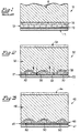
- FIG. 1 A sectional view of a prior art electrolytic cell 10 is shown in Fig. 1 as including alkali metal anode 11, native passive layer 12, electrolyte 16, and carbon coating 13, which is applied to the surface of anode 11 in a continuous (non-interrupted) orientation.
- the continuously applied coating is constructed from highly organized carbon, such as graphite, inasmuch as non-organized carbon, such as carbon black, will not enable operable ionic conductivity from the anode toward and into electrolyte 16.
- the particular alkali metal ions of the anode such as lithium ions, will chemically interact with the carbon (e.g. graphite). This interaction will then result in the chemical alteration of the alkali metal electrode to one having carbon as part of its composition.
- the electrode was originally constructed from lithium, it will become chemically altered to a carbon/lithium electrode - thereby resulting in a voltage drop in the electrolytic cell due to the thermal dynamic potential of such an "altered” electrode when compared against, for example, an "unaltered” lithium electrode.
- the present electrolytic cell 20 (which, in a preferred embodiment, comprises a rechargeable battery) is shown in Fig. 2 as comprising anode 22 (having a surface 23), cathode 24, electrolyte 26, native passive layer 27, substantially stable passivating layer 28 and substantially non-continuous electronically conductive particulate coating 30.
- anode 22 will be described as being substantially constructed from lithium, it is contemplated that the anode be constructed from other alkali metals as well.
- native passive layer 27 will be considered as comprising part of surface 23 of anode 22 inasmuch as such a native passive layer typically results during construction of the anode itself.
- electrolyte 26 consist of a liquid or solid electrolyte.
- a liquid electrolyte composed of 1.0M LiClO 4 in propylene carbonate (PC) as well as a solid/gel electrolyte based on PC-acrylates-LiAsF 6 , it will be recognized to those with ordinary skill in the art that other liquid and solid electrolytes can be used relative to the particular electrode construction.
- the non-continuously applied electronically conductive particulate coating 30 on surface 23 of anode 22 performs a dual function: 1) it serves as the means for lowering and substantially sustaining a relatively low interfacial resistance at the anode during the life of the cell; and 2) it serves as the means for provoking the formation of substantially stable passivating layer 28.
- This substantially stabilized passivating layer then serves as the means to substantially suppress dendritic growth at anode 22 during electrodeposition.
- substantially non-continuous electronically conductive particulate coating 30 is shown in Fig. 2 (as well as Fig. 3) as comprising carbon, it should be noted that other particulates are likewise contemplated -- provided they are "electronically conductive" and, are applied to the surface of the anode in a substantially “non-continuous” (interrupted) orientation. Furthermore, it is contemplated that both highly organized carbon, such as graphite, as well as non-organized carbon, such as carbon black, among others, will likewise be effectively utilized.
- electrolytic cell 40 is shown in Fig. 3 as including alkali metal anode 47 cathode 44, surface layer 45, electrolyte 46, substantially stable passivating layer 48 and substantially non-continuous electronically conductive particulate coating 50.
- Surface layer 45 which, in association with substantially stable passivating layer 48, further aides in the suppression of dendritic growth at the surface of anode 42.
- Surface layer 45 includes a copolymer which enables transfer of ions from anode 42 to electrolyte 46 and back into contact with the electrode, and, which is electronically conductive when it is in contact with the electrode.
- surface layer 45 further includes means for substantially obtaining chemical equilibrium between the surface layer and the electrode.
- the particular copolymer of surface layer 45 may include polyvinylnaphthalene and polyethylene oxide. Indeed, such a copolymer will exhibit ionic conductivity as a result of the polyethylene oxide, electronic conductivity due to the formation of naphthalene radical anions upon contact of the polyvinylnaphthalene with anode 42, and, chemical equilibrium between surface layer 45 and anode 42.
- surface layer 45 has been described as including polyvinylnaphthalene and polyethylene oxide, it will be understood that other compounds which exhibit both ionic and electronic conductivity are also contemplated for use.
- other polynuclear aromatic structures other than naphthalene
- Actual operation, and the process associated with such a surface layer is explained in pending U.S. Pat. Application Serial No. 08/290,017 entitled Electrolytic Cell and Electrolytic Process.
- the electrolytic process (which will be explained with respect to a rechargeable battery) relative to electrolytic cell 20 of Fig. 2, comprises connecting two electrodes 22 and 24 which are separated and positioned within electrolyte 26.
- anode 22 is constructed from lithium and the electrolyte may be in liquid or solid form
- Surface 23 of anode 22 is coated with electronically conductive particulate 30 in a substantially non-continuous orientation.
- the particulate (which comprises carbon), may be applied to surface 23 of anode 22 by various methods -- provided the method of treatment results in a substantially non-continuous (interrupted) coating on the anode surface.
- the particulate may be applied by wet spraying, rolling and/or electro-static spraying techniques, to name a few.
- substantially non-continuous electronically conductive particulate coating 30 has been applied to anode 22, and after interfacing the coated anode with electrolyte 26, the non-continuously applied coating will provoke formation of substantially stable passivating layer 28.
- This stable layer will, accordingly, serve to prevent further passivation at the anode, and, in turn, substantially suppress dendritic growth at the anode during electrodeposition.
- substantially non-continuously applied electronically conductive particulate coating 30 will enable transfer of lithium ions, from lithium anode 22, to pass primarily through the interrupted portions of the coating during oxidation, and reduction (as shown by the direction of the arrows in Fig. 2). Accordingly, during reduction, the lithium ions will be substantially precluded from forming with the particulate (e.g. carbon) ions, which would otherwise result if the coating was continuous, as opposed to non-continuous. Indeed, if the particulate was "continuously" applied to the surface of lithium anode 22, the lithium ions (which have passed into the electrolyte) would chemically react with the carbon ions of the particulate during, for example, reduction.
- particulate e.g. carbon
- the lithium electrode would become altered during electrodeposition to an electrode composed of carbon and lithium thereby lowering the cells voltage relative to the voltage when the lithium electrode is substantially unaltered during electrodeposition. Accordingly, the application of substantially "non-continuous" electronically conductive coating 30 at anode 22 will serve to maintain cell voltage, as well as serve to lower and substantially sustain interfacial resistance at anode 22 (relative to continuously coated and non-coated anodes) during the life of electrolytic cell 20.
- Experiment Nos. 1 through 7 utilized an electrolytic cell having the following common characteristics:
- the working electrode was not treated with any type of electronically conductive particulate surface.
- the difference between the working electrode and the reference electrode voltage was measured to be less than 5 mV.
- a cathodic current of 0.2 mA was then applied to the electrolytic cell for 60 minutes using a Solartron Electrochemical Interface 1286.
- the interfacial resistance of the lithium working electrode was then monitored by AC impedance spectroscopy, which was carried out in a typical frequency range of 65 k - 0.05Hz using a Solartron Frequency Response Analyzer 1250 connected to an Electrochemical Interface 1286.
- Non-treated Li The change of interfacial resistance of this untreated working electrode, over a period of time, was observed and then recorded in Table I (hereinbelow) under the column identified as "Non-treated Li.”
- Non-treated Li In the mixture solvent of ethylene carbonate and dimethyl carbonate (molar ratio of 3:2) with 1 M LiClO 4 salt Aging Time/hr Ratio of the interfacial Resistance (Interfacial Resistance/the Initial Interfacial Resistance of Lithium)
- the surface of the working electrode was treated with carbon powder obtained from pyrolysis of poly(paraphenylene) (also known as "PPP") in hydrogen at 700°C.
- This carbon powder was dispersed on the surface of the working electrode followed by rolling, to, in turn, result in the surface having a substantially "non-continuous" carbon coating.
- the potential difference between the working electrode and the reference electrode was measured at less than 20 mV.
- the working electrode was also cathodically treated with a 0.2 mA current. The change of the interfacial resistance of the non-continuously coated surface, over a period of time, was observed and then recorded in Table I (hereinabove) under the column identified as "Li Coating with carbon from Pyrolysis of PPP.”
- Non-treated Li In Electrolyte of propylene caronate with 1M LiclO 4 salt Aging Time/hr Ratio of interfacial resistance (interfacial resistance/initial interfacial resist ance of Li)
- Non-treated Li Coated with carbon from PPP Coated with L graphite Coated with black Treated with Mg powder 0 1.00 0.27 0.27 0.27 0.79 1 1.28 0.37 0.37 0.45 0.96 6 1.55 0.82 0.57 068 16 1.39 1.04 0 62 0.73 0.98 24 1.32 1.00 0.62 0.71 1.14 48 0.97 0.59 1.36 72 1.80 1.00 0.64 0.58 1.55 96 1.89 1.06 0.67 1.67 120 1.96 1.17 0.70 0.59 1.78
- the surface of the working electrode was treated with a non-continuous electronically conductive particulate coating of carbon from PPP.
- the potential difference between the working electrode and the reference electrode was measured to be less than 20 mV
- the change of interfacial resistance of this substantially non-continuously (interrupted) coated surface, over a period of time, was observed and recorded in Table II (hereinabove) in the column identified as "Coated with carbon from PPP.”
- the surface of the working electrode was prepared by suspending graphite (Lonza, 6 micro), or acetylene carbon black (Chevron 100% compressed), in hexane (Aldrich) followed by spraying the mixture on the surface with approximately 0.2 mg graphite (or alternatively carbon black), per square centimeter of the lithium surface.
- the solvent was then evaporated under vacuum and the potential difference between the working electrode and the reference electrode was measured to be less than 20 mV.
- the change of interfacial resistance of this substantially non-continuously coated surface, over a period of time, was observed and recorded Table II (hereinabove) in the columns identified as "Coated with Lonza graphite" and "Coated with carbon black.”
- the surface of the working electrode was prepared by dispersing magnesium powder (having a particle size larger than 100 mesh, Alfa) on the lithium surface followed by a rolling procedure.
- the potential difference between the working electrode and the reference electrode was measured to be less than 20 mV.
- the change of interfacial resistance of this substantially non-continuously coated surface, over a period of time, was observed and recorded in Table II (hereinabove) under the column identified as "Treated with Mg powder.”
- the lithium anode was not treated with any electronically conductive particulate layers.
- the effective area of the electrochemical cell was 20cm 2 ; the open circuit voltage of the cell was measured at approximately 3.50V; and, the internal impedance of the cell was measured by AC impedance at different aging times.
- Non-treated Li Cell resistance of Li anode/PC gel electrolyte/V2O5 cathode Aging Time/hr Cell Resistance/ ⁇ Non-treated Li Graphite-treated Li Carbon block-treated Li Treated with copper mesh 0 11.8 0.50 0.12 15 100 51.3 0.66 0.22 35
Landscapes
- Chemical & Material Sciences (AREA)
- Electrochemistry (AREA)
- Engineering & Computer Science (AREA)
- Chemical Kinetics & Catalysis (AREA)
- General Chemical & Material Sciences (AREA)
- Manufacturing & Machinery (AREA)
- Condensed Matter Physics & Semiconductors (AREA)
- Dispersion Chemistry (AREA)
- General Physics & Mathematics (AREA)
- Inorganic Chemistry (AREA)
- Physics & Mathematics (AREA)
- Materials Engineering (AREA)
- Battery Electrode And Active Subsutance (AREA)
- Secondary Cells (AREA)
Abstract
Description
- This present invention relates in general to secondary cells and, more particularly, to an electrolytic cell and electrolytic process associated therewith, wherein the interfacial resistance of the working electrode is substantially lowered and sustained over the life of the electrolytic cell.
- Rechargeable, or secondary electrolytic cells, have been known in the art for many, many years. Furthermore, secondary cells constructed with lithium anodes have likewise been known in the art. Although such rechargeable lithium batteries have proven to be functional, many of such batteries have been undesirable from a practicle standpoint due to one, or both, of the following shortcomings: 1) the cycle life of such lithium batteries are relatively short (compared to other types of secondary cells, such as nickel-cadmium) due to the formation of dendritic growth on the lithium electrode during electrodeposition; and/or 2) the inability to effectively lower and substantially sustain the interfacial resistance at the lithium anode during the life of the rechargeable lithium battery.
- With respect to suppression of dendritic growth, various approaches have been disclosed, including, but not limited to 1) the use of a copolymer layer applied to the surface of the lithium anode -- wherein the copolymer layer is ionically conductive, electronically conductive when in contact with the lithium anode and which enables chemical equilibrium between the copolymer layer itself and the lithium anode (details relevant to such a layer can be found in pending U.S. Pat. Application Ser. No. 08/290,017); as well as 2) applying a continuous coating of an electronically conductive layer, such as graphite, to the surface of the lithium anode.
- While such continuous electronically conductive layers have contributed to the suppression of dendritic growth -- through their ability to provoke the formation of a substantially stable passivating layer at the anode -- such continuous layers have also been responsible for lowering the cell's voltage, and, in turn, have shown little, if any, effect on lowering and sustaining interfacial resistance at the anode (when compared to anodes without such a layer). Indeed, when such a "continuous" layer is applied, the ions (associated with the anode, such as lithium ions which have passed into the electrolyte) chemically interact with the layer during, for example, reduction, wherein such an interaction chemically alters the composition of the electrode. For example, if the electrode is a lithium anode, and the layer is composed of carbon, the electrode will be altered during electrodeposition to an electrode composed of carbon and lithium (LiC6)― thereby lowering the cells voltage relative to the voltage when the lithium electrode is substantially unaltered during electrodeposition. As another example, if the electrode is a lithium anode and the layer is composed of aluminum, the electrode will be altered during electrodeposition to an electrode composed of lithium/aluminum alloy (LiAI), thereby lowering the cells voltage relative to the voltage when the lithium electrode is substantially unaltered during electrodeposition.
- Furthermore, when such a continuous electronically conductive particulate is applied to an anode, the layer is typically comprised of a highly crystalline material, such as graphite, as opposed to a non-crystalline material, such as carbon black. Indeed, such a highly crystalline graphite layer has proven necessary, when applied in a continuous orientation on the surface of the anode, for purposes of enabling the particular ions from the electrode to pass through the continuous carbon layer during oxidation and reduction.
- According to the present invention, there is provided an electrolytic cell (20) comprising:
- two electrodes (22, 24) and an electrolyte (26) wherein one of the two electrodes includes an anode (22) which is constructed from lithium having a surface (23) associated with the electrolyte (26),
- an electronically conductive, substantially non-continuous particulate coating (30) including carbon, applied to at least a portion of the surface (23) of the anode, such that a substantially low level interfacial resistance at the anode (22) is maintained during the life of the electrolytic cell and lithium ions are enabled to pass primarily through the interrupted portions of the substantially non-continuous particulate coating (30) including carbon; and
- a substantially stable passivating layer (28) whose formation is provoked by interfacing said coated anode with the electrolyte (26).
- The present invention comprises an electrolytic cell (or rechargeable battery) having two electrodes and an electrolyte, wherein one of the two electrodes includes an anode having a surface associated with the electrolyte. The invention further comprises means for substantially minimizing and sustaining interfacial resistance of the anode during the life of the electrolytic cell. The interfacial resistance means comprises an electronically conductive particulate coating applied to at least a portion of the surface of the anode in a substantially non-continuous orientation.
- In the invention, the electronically conductive particulate coating includes carbon, such as graphite, carbon black or carbon from pyrolysis of poly(para-phenylene). In addition, the anode is constructed from lithium.
- In the invention, the electrolytic cell further comprises means to substantially suppress dendritic growth atthe anode during electrodeposition. Such means comprises a substantially stable passivating layer associated with the anode.
- In a preferred embodiment of the invention, the means to substantially suppress dendritic growth includes a surface layer applied to the anode. The surface layer includes a copolymer which enables transfer of ions from the anode to the electrolyte and back into contact with the electrode, and, which is electronically conductive when it is in contact with the electrode. In addition, the copolymer further includes means for substantially obtaining chemical equilibrium between the surface layer and the electrode.
- According to the present invention, there is further provided an -electrolytic process comprising the steps of: connecting two electrodes (22, 24) separated and positioned within an electrolyte (26), at least one of the two electrodes (22, 24) being an anode (22) substantially constructed from lithium, the anode (22) having a surface (23) coated with an electronically conductive substantially non-continuous particulate coating (30) including carbon; and interfacing said coated anode with the electrolyte (26) to provoke formation of a substantially stable passivating layer (28), and_during as well as after formation of the stable passivating layer (28), ionizing metal atoms from the lithium anode (22) to provide lithium ions; transferring ions from the lithium anode (22) substantially through interrupted portions of the substantially non-continuous particulate coating (30) to the electrolyte.
- In a preferred embodiment, the electrolytic process further includes the step of provoking formation of a substantially stable passivating layer (28) to prevent further passivation at the anode (22), and, in turn, to substantially suppress dendritic growth at the anode (22) during electrodeposition.
- The present invention additionally comprises a process for constructing an electrolytic cell (20) comprising the steps of: applying an electronically conductive, substantially non-continuous particulate coating (30) including carbon onto an electrode (22) which is constructed from lithium, the substantially non-continuous particulate coating (30) serving for maintaining a substantially low level interface resistance at the anode (22) during the life of the electrolytic cell and enabling lithium ions to pass primarily through the interrupted portions of the substantially non-continuous particulate coating (30) including carbon; connecting the coated electrode (22) with another electrode (24) and separating both of the electrodes (22, 24) within an electrolyte (26); and forming a stable passivating layer (28) at the anode (22).
- The process further includes the step of applying a surface layer onto the electrode treated with the electronically conductive non-continuous particulate coating wherein such a surface layer is both ionically conductive and electronically conductive when in contact with the electrode. In this preferred process, the surface layer further comprises means for enabling chemical equilibrium between the surface layer and the electrode to which it is applied.
- Fig. 1 is a diagram of a prior art electrolytic cell in section;
- Fig. 2 is a diagram of one preferred embodiment of the present electrolytic cell; and
- Fig. 3 is another preferred embodiment of the present electrolytic cell.
-
- While this invention is susceptible of embodiment in many different forms, there is shown in the drawings and will herein be described in detail, two specific embodiments with the understanding that the present disclosure is to be considered as an exemplification of the principles of the invention and is not intended to limit the invention to the embodiments illustrated.
- A sectional view of a prior art
electrolytic cell 10 is shown in Fig. 1 as includingalkali metal anode 11, nativepassive layer 12,electrolyte 16, andcarbon coating 13, which is applied to the surface ofanode 11 in a continuous (non-interrupted) orientation. It should be noted that the continuously applied coating is constructed from highly organized carbon, such as graphite, inasmuch as non-organized carbon, such as carbon black, will not enable operable ionic conductivity from the anode toward and intoelectrolyte 16. - Furthermore, in such a prior art construction, the particular alkali metal ions of the anode, such as lithium ions, will chemically interact with the carbon (e.g. graphite). This interaction will then result in the chemical alteration of the alkali metal electrode to one having carbon as part of its composition. For example, if the electrode was originally constructed from lithium, it will become chemically altered to a carbon/lithium electrode - thereby resulting in a voltage drop in the electrolytic cell due to the thermal dynamic potential of such an "altered" electrode when compared against, for example, an "unaltered" lithium electrode.
- The present electrolytic cell 20 (which, in a preferred embodiment, comprises a rechargeable battery) is shown in Fig. 2 as comprising anode 22 (having a surface 23),
cathode 24,electrolyte 26, nativepassive layer 27, substantially stablepassivating layer 28 and substantially non-continuous electronically conductiveparticulate coating 30. Althoughanode 22 will be described as being substantially constructed from lithium, it is contemplated that the anode be constructed from other alkali metals as well. In addition, for purposes of the present disclosure, and as understood by those in the art, nativepassive layer 27 will be considered as comprising part ofsurface 23 ofanode 22 inasmuch as such a native passive layer typically results during construction of the anode itself. - As will be discussed in greater detail, it is contemplated that
electrolyte 26 consist of a liquid or solid electrolyte. Although detail will be provided on utilization of both a liquid electrolyte composed of 1.0M LiClO4 in propylene carbonate (PC), as well as a solid/gel electrolyte based on PC-acrylates-LiAsF6, it will be recognized to those with ordinary skill in the art that other liquid and solid electrolytes can be used relative to the particular electrode construction. - As will be explained, the non-continuously applied electronically conductive
particulate coating 30 onsurface 23 ofanode 22 performs a dual function: 1) it serves as the means for lowering and substantially sustaining a relatively low interfacial resistance at the anode during the life of the cell; and 2) it serves as the means for provoking the formation of substantiallystable passivating layer 28. This substantially stabilized passivating layer then serves as the means to substantially suppress dendritic growth atanode 22 during electrodeposition. - Although substantially non-continuous electronically conductive
particulate coating 30 is shown in Fig. 2 (as well as Fig. 3) as comprising carbon, it should be noted that other particulates are likewise contemplated -- provided they are "electronically conductive" and, are applied to the surface of the anode in a substantially "non-continuous" (interrupted) orientation. Furthermore, it is contemplated that both highly organized carbon, such as graphite, as well as non-organized carbon, such as carbon black, among others, will likewise be effectively utilized. - Another preferred embodiment of
electrolytic cell 40 is shown in Fig. 3 as includingalkali metal anode 47cathode 44,surface layer 45,electrolyte 46, substantiallystable passivating layer 48 and substantially non-continuous electronically conductiveparticulate coating 50.Surface layer 45, which, in association with substantiallystable passivating layer 48, further aides in the suppression of dendritic growth at the surface of anode 42.Surface layer 45 includes a copolymer which enables transfer of ions from anode 42 toelectrolyte 46 and back into contact with the electrode, and, which is electronically conductive when it is in contact with the electrode. In addition,surface layer 45 further includes means for substantially obtaining chemical equilibrium between the surface layer and the electrode. The particular copolymer ofsurface layer 45 may include polyvinylnaphthalene and polyethylene oxide. Indeed, such a copolymer will exhibit ionic conductivity as a result of the polyethylene oxide, electronic conductivity due to the formation of naphthalene radical anions upon contact of the polyvinylnaphthalene with anode 42, and, chemical equilibrium betweensurface layer 45 and anode 42. - Although
surface layer 45 has been described as including polyvinylnaphthalene and polyethylene oxide, it will be understood that other compounds which exhibit both ionic and electronic conductivity are also contemplated for use. For example, other polynuclear aromatic structures (other than naphthalene) may be used for achieving the formation of radical anions upon contact withsurface layer 45 of anode 42 -- toward obtaining the necessary electronic conductivity at the electrode/electrolyte interface. Actual operation, and the process associated with such a surface layer, is explained in pending U.S. Pat. Application Serial No. 08/290,017 entitled Electrolytic Cell and Electrolytic Process. - The electrolytic process (which will be explained with respect to a rechargeable battery) relative to
electrolytic cell 20 of Fig. 2, comprises connecting twoelectrodes electrolyte 26. In the preferred embodiment,anode 22 is constructed from lithium and the electrolyte may be in liquid orsolid form Surface 23 ofanode 22, is coated with electronicallyconductive particulate 30 in a substantially non-continuous orientation. The particulate (which comprises carbon), may be applied tosurface 23 ofanode 22 by various methods -- provided the method of treatment results in a substantially non-continuous (interrupted) coating on the anode surface. For example, the particulate may be applied by wet spraying, rolling and/or electro-static spraying techniques, to name a few. - As previously explained, after substantially non-continuous electronically conductive
particulate coating 30 has been applied toanode 22, and after interfacing the coated anode withelectrolyte 26, the non-continuously applied coating will provoke formation of substantiallystable passivating layer 28. This stable layer will, accordingly, serve to prevent further passivation at the anode, and, in turn, substantially suppress dendritic growth at the anode during electrodeposition. - During, as well as after, formation of
stable passivating layer 28, substantially non-continuously applied electronically conductiveparticulate coating 30 will enable transfer of lithium ions, fromlithium anode 22, to pass primarily through the interrupted portions of the coating during oxidation, and reduction (as shown by the direction of the arrows in Fig. 2). Accordingly, during reduction, the lithium ions will be substantially precluded from forming with the particulate (e.g. carbon) ions, which would otherwise result if the coating was continuous, as opposed to non-continuous. Indeed, if the particulate was "continuously" applied to the surface oflithium anode 22, the lithium ions (which have passed into the electrolyte) would chemically react with the carbon ions of the particulate during, for example, reduction. As a result, the lithium electrode would become altered during electrodeposition to an electrode composed of carbon and lithium thereby lowering the cells voltage relative to the voltage when the lithium electrode is substantially unaltered during electrodeposition. Accordingly, the application of substantially "non-continuous" electronicallyconductive coating 30 atanode 22 will serve to maintain cell voltage, as well as serve to lower and substantially sustain interfacial resistance at anode 22 (relative to continuously coated and non-coated anodes) during the life ofelectrolytic cell 20. - in support of the process and the above-identified exhibited characteristics of the electrolytic cell, and, more particularly, the effects of the applied non-continuous electronically conductive particulate coating relative to its ability to lower and substantially sustain interfacial resistance at
anode 22 during the life of the cell, several experiments were undertaken (using various electronically conductive particulates and electrolytes). Ten of such experiments, and their results, are outlined hereinbelow. - At the outset, it should be noted that Experiment Nos. 1 through 7 utilized an electrolytic cell having the following common characteristics:
- a piece of metallic lithium foil with a thickness of 50µm as the working electrode with an area of 2.54cm2;
- a lithium reference electrode;
- a glass fiber separator; and
- a lithium counter electrode.
- In this experiment, the working electrode was not treated with any type of electronically conductive particulate surface. The difference between the working electrode and the reference electrode voltage was measured to be less than 5 mV. A cathodic current of 0.2 mA was then applied to the electrolytic cell for 60 minutes using a Solartron Electrochemical Interface 1286. The interfacial resistance of the lithium working electrode was then monitored by AC impedance spectroscopy, which was carried out in a typical frequency range of 65 k - 0.05Hz using a Solartron Frequency Response Analyzer 1250 connected to an Electrochemical Interface 1286. The change of interfacial resistance of this untreated working electrode, over a period of time, was observed and then recorded in Table I (hereinbelow) under the column identified as "Non-treated Li."
In the mixture solvent of ethylene carbonate and dimethyl carbonate (molar ratio of 3:2) with 1 M LiClO4 salt Aging Time/hr Ratio of the interfacial Resistance (Interfacial Resistance/the Initial Interfacial Resistance of Lithium) Non-treated Li Li coating with carbon from Pryolysis of PPP Li coated with 1BA graphite 0 1 1.29 1.3 6 1.97 1.57 16 2.32 1.61 3.85 24 2.44 1.65 3.95 48 3.28 2.03 4.31 72 3.91 2.17 96 4.17 2.52 - In Experiment No. 2, the surface of the working electrode was treated with carbon powder obtained from pyrolysis of poly(paraphenylene) (also known as "PPP") in hydrogen at 700°C. This carbon powder was dispersed on the surface of the working electrode followed by rolling, to, in turn, result in the surface having a substantially "non-continuous" carbon coating. The potential difference between the working electrode and the reference electrode was measured at less than 20 mV. The working electrode was also cathodically treated with a 0.2 mA current. The change of the interfacial resistance of the non-continuously coated surface, over a period of time, was observed and then recorded in Table I (hereinabove) under the column identified as "Li Coating with carbon from Pyrolysis of PPP."
- In Experiment No. 3, a graphite, and more particulately, Brazilian graphite, IBA No. 6, was dispersed on, and then rolled, on the surface of the working electrode to, in turn, result in a surface having a substantially "non-continuous" electronically conductive graphite layer thereon. The potential difference between the working electrode and the reference electrode was measured to be less than 20 mV. The working electrode was cathodically treated with a 0.2 mA current. The change of interfacial resistance of this non-continuously coated surface, over a period of time, was observed and recorded in Table I (hereinabove) under the column identified as "Li Coated with IBA graphite."
- In Experiment No. 4, and as previously explained, the electrolyte was changed to 1.0M LiClO4 in propylene carbonate. In this particular experiment, the working electrode was not treated/coated with any type of electronically conductive particulate. As was done in Experiment No. 1, a cathodic current of 0.2 mA was applied to the cell for 60 minutes, and, the interfacial resistance of the lithium working electrode, over a period of time, was observed and recorded in Table II (hereinbelow) under the column identified as "Non-treated Li."
In Electrolyte of propylene caronate with 1M LiclO4 salt Aging Time/hr Ratio of interfacial resistance (interfacial resistance/initial interfacial resist ance of Li) Non-treated Li Coated with carbon from PPP Coated with L graphite Coated with black Treated with Mg powder 0 1.00 0.27 0.27 0.27 0.79 1 1.28 0.37 0.37 0.45 0.96 6 1.55 0.82 0.57 068 16 1.39 1.04 0 62 0.73 0.98 24 1.32 1.00 0.62 0.71 1.14 48 0.97 0.59 1.36 72 1.80 1.00 0.64 0.58 1.55 96 1.89 1.06 0.67 1.67 120 1.96 1.17 0.70 0.59 1.78 - With respect to Experiment No. 5, as well as Experiment Nos. 6 through 8, the respective surfaces of the corresponding working electrodeswere treated with substantially "non-continuous" electronically conductive particulate coatings. Indeed, as will be observed, such non-continuously applied particulate coatings resulted in working electrodes having lower, and, in some cases, significantly lower, interfacial resistance over the measured period of time.
- in particular, and with respect to Experiment No. 5, the surface of the working electrode was treated with a non-continuous electronically conductive particulate coating of carbon from PPP. The potential difference between the working electrode and the reference electrode was measured to be less than 20 mV The change of interfacial resistance of this substantially non-continuously (interrupted) coated surface, over a period of time, was observed and recorded in Table II (hereinabove) in the column identified as "Coated with carbon from PPP."
- In Experiment No. 6, the surface of the working electrode was prepared by suspending graphite (Lonza, 6 micro), or acetylene carbon black (Chevron 100% compressed), in hexane (Aldrich) followed by spraying the mixture on the surface with approximately 0.2 mg graphite (or alternatively carbon black), per square centimeter of the lithium surface. The solvent was then evaporated under vacuum and the potential difference between the working electrode and the reference electrode was measured to be less than 20 mV. The change of interfacial resistance of this substantially non-continuously coated surface, over a period of time, was observed and recorded Table II (hereinabove) in the columns identified as "Coated with Lonza graphite" and "Coated with carbon black."
- In Experiment No. 7, the surface of the working electrode was prepared by dispersing magnesium powder (having a particle size larger than 100 mesh, Alfa) on the lithium surface followed by a rolling procedure. The potential difference between the working electrode and the reference electrode was measured to be less than 20 mV. The change of interfacial resistance of this substantially non-continuously coated surface, over a period of time, was observed and recorded in Table II (hereinabove) under the column identified as "Treated with Mg powder."
- In Experiment Nos. 8 through 10, an electrochemical cell was assembled wherein the cell included the following common characteristics:
- a composite cathode was made from V2O5(75% wt), EPDM binder (3% wt), graphite and carbon black (Chevron 100% compressed);
- a gel electrolyte based on PC-acrylates-LiAsF6; and
- a metallic lithium anode.
- Specifically, with respect to Experiment No. 8, the lithium anode was not treated with any electronically conductive particulate layers. Furthermore, in this experiment, as well as in Experiment Nos. 9 and 10, the effective area of the electrochemical cell was 20cm2; the open circuit voltage of the cell was measured at approximately 3.50V; and, the internal impedance of the cell was measured by AC impedance at different aging times. With respect to Experiment No. 8, the change of the cell resistance, over a period of time, was observed and recorded in Table III (hereinbelow) under the column identified as "Non-treated Li."
Cell resistance of Li anode/PC gel electrolyte/V2O5 cathode Aging Time/hr Cell Resistance/Ω Non-treated Li Graphite-treated Li Carbon block-treated Li Treated with copper mesh 0 11.8 0.50 0.12 15 100 51.3 0.66 0.22 35 - In Experiment No. 9, the anode was treated with a substantially non-continuous coating of graphite or, alternatively, carbon black. The change of the cell resistance, over a period of time, was observed and recorded in Table III (hereinabove) under the columns identified as "Graphite-treated Li" and "Carbon black-treated Li."
- In Experiment No. 10, the anode was treated with copper mesh rolled on to the surface of the anode in a substantially non-continuous orientation. The change of cell resistance, over a period of time, was observed and recorded in Table III (hereinabove) under the column identified as "Treated with copper mesh."
- As previously explained, and as exhibited in Experiment Nos. 2 through 10, the utilization of a substantially non-continuous electronically conductive particulate including carbon, when applied to the surface of a lithium anode, in, for example, a rechargeable battery, served as the impetus toward lowering and substantially sustaining interfacial resistance at the anode, when compared against non-treated electrodes, as well as electrodes treated with a substantially continuous layer of an electronically conductive material. Furthermore, the use of such a non-continuous electronically conductive particulate coating including carbon also demonstrated the ability to provoke the formation of a substantially stable passivating layer at the surface of the anode to, in turn, substantially suppress dendritic growth at the interface.
- While preferred embodiments have been explained with respect to applications of the particulate coating relative to the anode, it will be understood that such a non-continuous electronically conductive coating can be applied to cathodes as well.
Claims (9)
- An electrolytic cell (20) comprising:two electrodes (22, 24) and an electrolyte (26) wherein one of the two electrodes includes an anode (22) which is constructed from lithium having a surface (23) associated with the electrolyte (26),an electronically conductive, substantially non-continuous particulate coating (30) including carbon, applied to at least a portion of the surface (23) of the anode, such that a substantially low level interfacial resistance at the anode (22) is maintained during the life of the electrolytic cell and lithium ions are enabled to pass primarily through the interrupted portions of the substantially non-continuous particulate coating (30) including carbon;a substantially stable passivating layer (28) whose formation is provoked by interfacing said coated anode with the electrolyte (26).
- The electrolytic cell (20) according to Claim 1 further containing a surface layer (45) applied to the anode (22), wherein the surface layer (45) includes a copolymer which enables transfer of ion from the anode (22) to the electrolyte (26) and back into contact with the electrode, and, which is electronically conductive when it is in contact with the electrode.
- The electrolytic cell (20) according to Claim 1 or 2, wherein the copolymer further includes means for substantially obtaining chemical equilibrium between the surface layer (45) and the electrode (22).
- A rechargeable battery comprising an electrolytic cell (20) according to anyone of the preceding Claims 1 to 3.
- An electrolytic process comprising the steps of:connecting two electrodes (22, 24) separated and positioned within an electrolyte (26), at least one of the two electrodes (22, 24) being an anode (22) substantially constructed from lithium, the anode (22) having a surface (23) coated with an electronically conductive substantially non-continuous particulate coating (30) including carbon; andinterfacing said coated anode with the electrolyte (26) to provoke formation of a substantially stable passivating layer (28), andduring as well as after formation of the stable passivating layer (28), ionizing metal atoms from the lithium anode (22) to provide lithium ions;transferring ions from the lithium anode (22) substantial through interrupted portions of the substantially non-continuous particulate coating (30) to the electrolyte.
- The electrolytic process according to Claim 5 further including the step of provoking formation of a substantially stable passivating layer (28) to prevent further passivation at the anode (22), and, in turn, to substantially suppress dendritic growth at the anode (22) during electrodeposition.
- A process for constructing an electrolytic cell (20) comprising the steps of:applying an electronically conductive, substantially non-continuous particulate coating (30) including carbon onto an electrode (22) which is constructed from lithium, the substantially non-continuous particulate coating (30) serving for maintaining a substantially low level interfacial resistance at the anode (22) during the life of the electrolytic cell and enabling lithium ions to pass primarily through the interrupted portions of the substantially non-continuous particulate coating (30) including carbon;connecting the coated electrode (22) with another electrode (24) and separating both of the electrodes (22, 24) within an electrolyte (26); andforming a stable passivating layer (28) at the anode (22).
- The process according to Claim 7 further including the step of applying a surface layer (45) onto the electrode (22) coated with the electronically conductive substantially non-continuous particulate coating (30), the surface layer (45) being electronically conductive and ionically conductive.
- The process according to Claim 8, wherein the surface layer (45) comprises means for enabling chemical equilibrium between the surface layer (45) and the electrode (22) to which it is applied.
Applications Claiming Priority (3)
| Application Number | Priority Date | Filing Date | Title |
|---|---|---|---|
| US314878 | 1994-09-29 | ||
| US08/314,878 US5503946A (en) | 1994-09-29 | 1994-09-29 | Particulate interface for electrolytic cells and electrolytic process |
| PCT/US1995/010608 WO1996010271A1 (en) | 1994-09-29 | 1995-08-18 | Particulate interface for electrolytic cells and electrolytic process |
Publications (2)
| Publication Number | Publication Date |
|---|---|
| EP0783769A1 EP0783769A1 (en) | 1997-07-16 |
| EP0783769B1 true EP0783769B1 (en) | 2004-01-14 |
Family
ID=23221869
Family Applications (1)
| Application Number | Title | Priority Date | Filing Date |
|---|---|---|---|
| EP95931547A Expired - Lifetime EP0783769B1 (en) | 1994-09-29 | 1995-08-18 | Particulate interface for electrolytic cells and electrolytic process |
Country Status (6)
| Country | Link |
|---|---|
| US (1) | US5503946A (en) |
| EP (1) | EP0783769B1 (en) |
| JP (1) | JP2002516643A (en) |
| DE (1) | DE69532450T2 (en) |
| IL (1) | IL115190A0 (en) |
| WO (1) | WO1996010271A1 (en) |
Cited By (1)
| Publication number | Priority date | Publication date | Assignee | Title |
|---|---|---|---|---|
| CN107851835A (en) * | 2015-07-27 | 2018-03-27 | 3M创新有限公司 | Graphite modified metal lithium electrode |
Families Citing this family (22)
| Publication number | Priority date | Publication date | Assignee | Title |
|---|---|---|---|---|
| FR2729009B1 (en) * | 1994-12-28 | 1997-01-31 | Accumulateurs Fixes | BIFUNCTIONAL ELECTRODE FOR ELECTROCHEMICAL GENERATOR OR SUPERCAPACITOR AND ITS MANUFACTURING PROCESS |
| IL112907A (en) * | 1995-03-07 | 2000-08-31 | Univ Ramot | Lithium batteries having an anode with solid electrolyte interface |
| EP0752727B1 (en) * | 1995-07-03 | 1999-12-01 | General Motors Corporation | Method for manufacturing lithium-deactivated carbon anodes |
| JP3601124B2 (en) * | 1995-09-22 | 2004-12-15 | 株式会社デンソー | A positive electrode active material of a secondary battery using a non-aqueous solution, and a positive electrode. |
| US5756232A (en) * | 1996-09-25 | 1998-05-26 | Alliant Techsystems Inc. | Lithium metal anodes |
| FR2760292B1 (en) | 1997-03-03 | 1999-04-02 | Alsthom Cge Alcatel | METHOD FOR MANUFACTURING AN ORGANIC ELECTROCHEMICAL ELECTROCHEMICAL GENERATOR HAVING A UNIT STRUCTURE |
| FR2766296B1 (en) | 1997-07-17 | 1999-08-20 | Alsthom Cge Alcatel | METHOD FOR MANUFACTURING AN ELECTROCHEMICAL GENERATOR WITH UNIT STRUCTURE |
| FR2766295B1 (en) | 1997-07-17 | 1999-09-24 | Alsthom Cge Alcatel | POLYMERIC SEPARATOR, MANUFACTURING PROCESS AND ELECTROCHEMICAL GENERATOR INCLUDING IT |
| US6171723B1 (en) * | 1997-10-10 | 2001-01-09 | 3M Innovative Properties Company | Batteries with porous components |
| US6416901B1 (en) | 1999-07-06 | 2002-07-09 | Mitsubishi Chemical Corporation | Electrochemical cell having an interface modifying component and associated fabrication process |
| JP4053819B2 (en) * | 2002-05-30 | 2008-02-27 | 株式会社オハラ | Lithium ion secondary battery |
| RU2242825C1 (en) * | 2003-05-23 | 2004-12-20 | ООО Инженерная фирма "Орион ХИТ" | Li/SO2 CELL |
| CN100514720C (en) * | 2004-11-26 | 2009-07-15 | 松下电器产业株式会社 | Lithium primary battery and method for producing the same |
| US8062793B2 (en) | 2004-11-26 | 2011-11-22 | Panasonic Corporation | Lithium primary battery and manufacturing method therefor |
| FR2902576B1 (en) * | 2006-06-16 | 2009-05-29 | Univ Technologie De Varsovie | METHOD FOR MODIFYING THE INTERFACIAL RESISTANCE OF A METAL LITHIUM ELECTRODE |
| WO2008153562A1 (en) * | 2007-06-11 | 2008-12-18 | Midwest Research Institute | Anodic dendritic growth suppression system for secondary lithium batteries |
| JP5400451B2 (en) * | 2008-04-18 | 2014-01-29 | パナソニック株式会社 | Negative electrode for lithium primary battery and lithium primary battery |
| JP4952680B2 (en) * | 2008-08-05 | 2012-06-13 | ソニー株式会社 | Lithium ion secondary battery and negative electrode for lithium ion secondary battery |
| EP2577776A4 (en) | 2010-06-02 | 2014-07-23 | Univ Florida State Res Found | ELECTROCHEMICAL CAPACITORS WITH HIGH ENERGY DENSITY |
| DE102013220785A1 (en) * | 2013-10-15 | 2015-04-16 | Robert Bosch Gmbh | Lithium electrode for a lithium-ion battery and method for its production |
| AU2020376780A1 (en) | 2019-10-28 | 2022-03-10 | Jongsoo Cho | Lithium metal anodes and method of making same |
| DE102021211680B4 (en) | 2021-10-15 | 2023-05-04 | Volkswagen Aktiengesellschaft | Electrode for a lithium ion cell, lithium ion cell, method of manufacturing an electrode for a lithium ion cell |
Family Cites Families (10)
| Publication number | Priority date | Publication date | Assignee | Title |
|---|---|---|---|---|
| CA1173900A (en) * | 1982-06-30 | 1984-09-04 | Hydro-Quebec | Composite and flexible anodes for non aqueous lithium cells |
| JPS59143268A (en) * | 1983-02-03 | 1984-08-16 | Hitachi Maxell Ltd | Solid electrolyte battery |
| JPS6376261A (en) * | 1986-09-17 | 1988-04-06 | Showa Denko Kk | secondary battery |
| US4808496A (en) * | 1987-03-13 | 1989-02-28 | Mhb Joint Venture | Electrode construction for solid state electrochemical cell |
| US5166008A (en) * | 1988-03-31 | 1992-11-24 | Canon Kabushiki Kaisha | Polymer gel-coated conductor, method of producing the same, and electric cell making use of the same |
| JP2923560B2 (en) * | 1988-04-28 | 1999-07-26 | 株式会社日立製作所 | Secondary battery and its negative electrode |
| US5342710A (en) * | 1993-03-30 | 1994-08-30 | Valence Technology, Inc. | Lakyer for stabilization of lithium anode |
| US5366829A (en) * | 1993-06-14 | 1994-11-22 | Valence Technology, Inc. | Method of forming an anode material for lithium-containing solid electrochemical cells |
| US5387479A (en) * | 1993-06-16 | 1995-02-07 | Valence Technology, Inc. | Electrodes for rechargeable lithium batteries |
| US5434021A (en) * | 1994-08-12 | 1995-07-18 | Arthur D. Little, Inc. | Secondary electrolytic cell and electrolytic process |
-
1994
- 1994-09-29 US US08/314,878 patent/US5503946A/en not_active Expired - Lifetime
-
1995
- 1995-08-18 EP EP95931547A patent/EP0783769B1/en not_active Expired - Lifetime
- 1995-08-18 WO PCT/US1995/010608 patent/WO1996010271A1/en not_active Ceased
- 1995-08-18 JP JP51174596A patent/JP2002516643A/en not_active Ceased
- 1995-08-18 DE DE69532450T patent/DE69532450T2/en not_active Expired - Lifetime
- 1995-09-06 IL IL11519095A patent/IL115190A0/en unknown
Cited By (1)
| Publication number | Priority date | Publication date | Assignee | Title |
|---|---|---|---|---|
| CN107851835A (en) * | 2015-07-27 | 2018-03-27 | 3M创新有限公司 | Graphite modified metal lithium electrode |
Also Published As
| Publication number | Publication date |
|---|---|
| DE69532450T2 (en) | 2004-11-04 |
| EP0783769A1 (en) | 1997-07-16 |
| WO1996010271A1 (en) | 1996-04-04 |
| IL115190A0 (en) | 1995-12-31 |
| US5503946A (en) | 1996-04-02 |
| JP2002516643A (en) | 2002-06-04 |
| DE69532450D1 (en) | 2004-02-19 |
Similar Documents
| Publication | Publication Date | Title |
|---|---|---|
| EP0783769B1 (en) | Particulate interface for electrolytic cells and electrolytic process | |
| US5434021A (en) | Secondary electrolytic cell and electrolytic process | |
| CN1839497B (en) | Electrode and method for producing same | |
| Peramunage et al. | Polyacrylonitrile‐based electrolytes with ternary solvent mixtures as plasticizers | |
| US7482096B2 (en) | Alleviation of voltage delay in lithium-liquid depolarizer/electrolyte solvent battery cells | |
| EP1787340B1 (en) | Electrode, and method for preparing the same | |
| EP0797846B1 (en) | Electrolytic cell and electrolytic process | |
| Doeff et al. | Thin film rechargeable room temperature batteries using solid redox polymerization electrodes | |
| JP2023513815A (en) | Anode piece, battery and electronic device employing said electrode piece | |
| HK113297A (en) | Electrochemical secondary battery | |
| WO1999019931A1 (en) | Liquid electrolyte lithium-sulfur batteries | |
| US20030096163A1 (en) | Non aqueous electrolyte secondary battery | |
| CN103858195A (en) | Lithium ion capacitor, power storage device, power storage system | |
| US6844114B2 (en) | LiPO3-based coating for collectors | |
| JP2002203607A (en) | Electrochemical cell consisting of alkaline metal cell or ion electrochemical cell including double collector cathode structure using same active material of different thicknesses | |
| Meitav et al. | Calcium‐Ca (AlCl4) 2‐Thionyl Chloride Cell: Performance and Safety | |
| EP1755180A1 (en) | Negative electrode material of lithium secondary cell and lithium secondary cell | |
| WO2022211866A1 (en) | Low voltage sacrificial electrodes | |
| US4461815A (en) | Ca Electrochemical cell | |
| JP2012129484A (en) | Hybrid solid electrolyte membrane, method of manufacturing the same, and lithium ion capacitor comprising the same | |
| Geronov et al. | The secondary lithium—aluminium electrode at room temperature: I. Cycling in LiClO4—propylene carbonate solutions | |
| JPH05234583A (en) | Negative electrode for lithium secondary battery and lithium secondary battery using it | |
| RU2583453C2 (en) | Primary chemical current source | |
| KR102871930B1 (en) | Lithium metal anode for Lithium batteries | |
| AU566641B2 (en) | Nonaqueous electrochemical cell |
Legal Events
| Date | Code | Title | Description |
|---|---|---|---|
| PUAI | Public reference made under article 153(3) epc to a published international application that has entered the european phase |
Free format text: ORIGINAL CODE: 0009012 |
|
| 17P | Request for examination filed |
Effective date: 19970418 |
|
| AK | Designated contracting states |
Kind code of ref document: A1 Designated state(s): DE |
|
| 17Q | First examination report despatched |
Effective date: 19970811 |
|
| RIN1 | Information on inventor provided before grant (corrected) |
Inventor name: GARY, RICHARD Inventor name: SHI, JIE Inventor name: FAUTEUX, DENIS, G. |
|
| RAP1 | Party data changed (applicant data changed or rights of an application transferred) |
Owner name: MITSUBISHI CHEMICAL CORPORATION |
|
| GRAH | Despatch of communication of intention to grant a patent |
Free format text: ORIGINAL CODE: EPIDOS IGRA |
|
| GRAS | Grant fee paid |
Free format text: ORIGINAL CODE: EPIDOSNIGR3 |
|
| GRAA | (expected) grant |
Free format text: ORIGINAL CODE: 0009210 |
|
| AK | Designated contracting states |
Kind code of ref document: B1 Designated state(s): DE |
|
| REF | Corresponds to: |
Ref document number: 69532450 Country of ref document: DE Date of ref document: 20040219 Kind code of ref document: P |
|
| RAP2 | Party data changed (patent owner data changed or rights of a patent transferred) |
Owner name: MITSUBISHI CHEMICAL CORPORATION |
|
| PLBE | No opposition filed within time limit |
Free format text: ORIGINAL CODE: 0009261 |
|
| STAA | Information on the status of an ep patent application or granted ep patent |
Free format text: STATUS: NO OPPOSITION FILED WITHIN TIME LIMIT |
|
| 26N | No opposition filed |
Effective date: 20041015 |
|
| PGFP | Annual fee paid to national office [announced via postgrant information from national office to epo] |
Ref country code: DE Payment date: 20140813 Year of fee payment: 20 |
|
| REG | Reference to a national code |
Ref country code: DE Ref legal event code: R071 Ref document number: 69532450 Country of ref document: DE |