EP0783232A2 - Méthode et appareil pour adapter un ordinateur à une communication sans fil - Google Patents
Méthode et appareil pour adapter un ordinateur à une communication sans fil Download PDFInfo
- Publication number
- EP0783232A2 EP0783232A2 EP96309338A EP96309338A EP0783232A2 EP 0783232 A2 EP0783232 A2 EP 0783232A2 EP 96309338 A EP96309338 A EP 96309338A EP 96309338 A EP96309338 A EP 96309338A EP 0783232 A2 EP0783232 A2 EP 0783232A2
- Authority
- EP
- European Patent Office
- Prior art keywords
- audio
- video
- bandwidth
- computer
- signal
- Prior art date
- Legal status (The legal status is an assumption and is not a legal conclusion. Google has not performed a legal analysis and makes no representation as to the accuracy of the status listed.)
- Withdrawn
Links
- 238000004891 communication Methods 0.000 title claims abstract description 33
- 238000000034 method Methods 0.000 title claims abstract description 25
- 230000005236 sound signal Effects 0.000 claims abstract description 38
- 238000007906 compression Methods 0.000 claims abstract description 23
- 230000006835 compression Effects 0.000 claims abstract description 23
- 230000005540 biological transmission Effects 0.000 claims description 25
- 238000003860 storage Methods 0.000 claims description 8
- 230000008859 change Effects 0.000 claims description 4
- 238000012545 processing Methods 0.000 claims description 3
- 230000004044 response Effects 0.000 claims description 3
- 238000001228 spectrum Methods 0.000 claims description 3
- 230000002093 peripheral effect Effects 0.000 claims description 2
- 238000009434 installation Methods 0.000 claims 2
- 239000003086 colorant Substances 0.000 description 14
- 230000003247 decreasing effect Effects 0.000 description 7
- 239000002131 composite material Substances 0.000 description 5
- 238000010586 diagram Methods 0.000 description 5
- 230000010363 phase shift Effects 0.000 description 5
- 230000008901 benefit Effects 0.000 description 4
- RYGMFSIKBFXOCR-UHFFFAOYSA-N Copper Chemical compound [Cu] RYGMFSIKBFXOCR-UHFFFAOYSA-N 0.000 description 3
- 238000013459 approach Methods 0.000 description 3
- 238000009125 cardiac resynchronization therapy Methods 0.000 description 3
- 230000006870 function Effects 0.000 description 3
- 238000004088 simulation Methods 0.000 description 3
- 230000007480 spreading Effects 0.000 description 3
- 238000003892 spreading Methods 0.000 description 3
- 230000002238 attenuated effect Effects 0.000 description 2
- 230000010267 cellular communication Effects 0.000 description 2
- 230000001413 cellular effect Effects 0.000 description 2
- 229910052802 copper Inorganic materials 0.000 description 2
- 239000010949 copper Substances 0.000 description 2
- 238000012937 correction Methods 0.000 description 2
- 238000011161 development Methods 0.000 description 2
- 239000000835 fiber Substances 0.000 description 2
- 238000002955 isolation Methods 0.000 description 2
- 238000012544 monitoring process Methods 0.000 description 2
- 238000012935 Averaging Methods 0.000 description 1
- 238000011949 advanced processing technology Methods 0.000 description 1
- 230000003321 amplification Effects 0.000 description 1
- 230000015572 biosynthetic process Effects 0.000 description 1
- 230000015556 catabolic process Effects 0.000 description 1
- 238000005314 correlation function Methods 0.000 description 1
- 238000013144 data compression Methods 0.000 description 1
- 238000006731 degradation reaction Methods 0.000 description 1
- 238000009826 distribution Methods 0.000 description 1
- 230000000694 effects Effects 0.000 description 1
- 238000005516 engineering process Methods 0.000 description 1
- 238000004880 explosion Methods 0.000 description 1
- 230000006872 improvement Effects 0.000 description 1
- 238000004519 manufacturing process Methods 0.000 description 1
- 238000013507 mapping Methods 0.000 description 1
- 239000011159 matrix material Substances 0.000 description 1
- 239000000203 mixture Substances 0.000 description 1
- 238000012986 modification Methods 0.000 description 1
- 230000004048 modification Effects 0.000 description 1
- 238000003199 nucleic acid amplification method Methods 0.000 description 1
- 238000013139 quantization Methods 0.000 description 1
- 230000009467 reduction Effects 0.000 description 1
- 230000033458 reproduction Effects 0.000 description 1
- 239000004065 semiconductor Substances 0.000 description 1
- 230000003595 spectral effect Effects 0.000 description 1
- 230000001360 synchronised effect Effects 0.000 description 1
Images
Classifications
-
- H—ELECTRICITY
- H04—ELECTRIC COMMUNICATION TECHNIQUE
- H04W—WIRELESS COMMUNICATION NETWORKS
- H04W72/00—Local resource management
- H04W72/04—Wireless resource allocation
- H04W72/044—Wireless resource allocation based on the type of the allocated resource
- H04W72/0453—Resources in frequency domain, e.g. a carrier in FDMA
-
- H—ELECTRICITY
- H04—ELECTRIC COMMUNICATION TECHNIQUE
- H04N—PICTORIAL COMMUNICATION, e.g. TELEVISION
- H04N21/00—Selective content distribution, e.g. interactive television or video on demand [VOD]
- H04N21/20—Servers specifically adapted for the distribution of content, e.g. VOD servers; Operations thereof
- H04N21/23—Processing of content or additional data; Elementary server operations; Server middleware
- H04N21/236—Assembling of a multiplex stream, e.g. transport stream, by combining a video stream with other content or additional data, e.g. inserting a URL [Uniform Resource Locator] into a video stream, multiplexing software data into a video stream; Remultiplexing of multiplex streams; Insertion of stuffing bits into the multiplex stream, e.g. to obtain a constant bit-rate; Assembling of a packetised elementary stream
- H04N21/2365—Multiplexing of several video streams
- H04N21/23655—Statistical multiplexing, e.g. by controlling the encoder to alter its bitrate to optimize the bandwidth utilization
-
- H—ELECTRICITY
- H04—ELECTRIC COMMUNICATION TECHNIQUE
- H04N—PICTORIAL COMMUNICATION, e.g. TELEVISION
- H04N21/00—Selective content distribution, e.g. interactive television or video on demand [VOD]
- H04N21/20—Servers specifically adapted for the distribution of content, e.g. VOD servers; Operations thereof
- H04N21/23—Processing of content or additional data; Elementary server operations; Server middleware
- H04N21/236—Assembling of a multiplex stream, e.g. transport stream, by combining a video stream with other content or additional data, e.g. inserting a URL [Uniform Resource Locator] into a video stream, multiplexing software data into a video stream; Remultiplexing of multiplex streams; Insertion of stuffing bits into the multiplex stream, e.g. to obtain a constant bit-rate; Assembling of a packetised elementary stream
- H04N21/2368—Multiplexing of audio and video streams
-
- H—ELECTRICITY
- H04—ELECTRIC COMMUNICATION TECHNIQUE
- H04N—PICTORIAL COMMUNICATION, e.g. TELEVISION
- H04N21/00—Selective content distribution, e.g. interactive television or video on demand [VOD]
- H04N21/20—Servers specifically adapted for the distribution of content, e.g. VOD servers; Operations thereof
- H04N21/23—Processing of content or additional data; Elementary server operations; Server middleware
- H04N21/238—Interfacing the downstream path of the transmission network, e.g. adapting the transmission rate of a video stream to network bandwidth; Processing of multiplex streams
- H04N21/2383—Channel coding or modulation of digital bit-stream, e.g. QPSK modulation
-
- H—ELECTRICITY
- H04—ELECTRIC COMMUNICATION TECHNIQUE
- H04N—PICTORIAL COMMUNICATION, e.g. TELEVISION
- H04N21/00—Selective content distribution, e.g. interactive television or video on demand [VOD]
- H04N21/20—Servers specifically adapted for the distribution of content, e.g. VOD servers; Operations thereof
- H04N21/23—Processing of content or additional data; Elementary server operations; Server middleware
- H04N21/238—Interfacing the downstream path of the transmission network, e.g. adapting the transmission rate of a video stream to network bandwidth; Processing of multiplex streams
- H04N21/2385—Channel allocation; Bandwidth allocation
-
- H—ELECTRICITY
- H04—ELECTRIC COMMUNICATION TECHNIQUE
- H04N—PICTORIAL COMMUNICATION, e.g. TELEVISION
- H04N21/00—Selective content distribution, e.g. interactive television or video on demand [VOD]
- H04N21/40—Client devices specifically adapted for the reception of or interaction with content, e.g. set-top-box [STB]; Operations thereof
- H04N21/41—Structure of client; Structure of client peripherals
- H04N21/426—Internal components of the client ; Characteristics thereof
-
- H—ELECTRICITY
- H04—ELECTRIC COMMUNICATION TECHNIQUE
- H04N—PICTORIAL COMMUNICATION, e.g. TELEVISION
- H04N21/00—Selective content distribution, e.g. interactive television or video on demand [VOD]
- H04N21/40—Client devices specifically adapted for the reception of or interaction with content, e.g. set-top-box [STB]; Operations thereof
- H04N21/43—Processing of content or additional data, e.g. demultiplexing additional data from a digital video stream; Elementary client operations, e.g. monitoring of home network or synchronising decoder's clock; Client middleware
- H04N21/434—Disassembling of a multiplex stream, e.g. demultiplexing audio and video streams, extraction of additional data from a video stream; Remultiplexing of multiplex streams; Extraction or processing of SI; Disassembling of packetised elementary stream
- H04N21/4341—Demultiplexing of audio and video streams
-
- H—ELECTRICITY
- H04—ELECTRIC COMMUNICATION TECHNIQUE
- H04N—PICTORIAL COMMUNICATION, e.g. TELEVISION
- H04N21/00—Selective content distribution, e.g. interactive television or video on demand [VOD]
- H04N21/40—Client devices specifically adapted for the reception of or interaction with content, e.g. set-top-box [STB]; Operations thereof
- H04N21/43—Processing of content or additional data, e.g. demultiplexing additional data from a digital video stream; Elementary client operations, e.g. monitoring of home network or synchronising decoder's clock; Client middleware
- H04N21/438—Interfacing the downstream path of the transmission network originating from a server, e.g. retrieving encoded video stream packets from an IP network
- H04N21/4382—Demodulation or channel decoding, e.g. QPSK demodulation
-
- H—ELECTRICITY
- H04—ELECTRIC COMMUNICATION TECHNIQUE
- H04N—PICTORIAL COMMUNICATION, e.g. TELEVISION
- H04N21/00—Selective content distribution, e.g. interactive television or video on demand [VOD]
- H04N21/60—Network structure or processes for video distribution between server and client or between remote clients; Control signalling between clients, server and network components; Transmission of management data between server and client, e.g. sending from server to client commands for recording incoming content stream; Communication details between server and client
- H04N21/61—Network physical structure; Signal processing
- H04N21/6106—Network physical structure; Signal processing specially adapted to the downstream path of the transmission network
- H04N21/6131—Network physical structure; Signal processing specially adapted to the downstream path of the transmission network involving transmission via a mobile phone network
-
- H—ELECTRICITY
- H04—ELECTRIC COMMUNICATION TECHNIQUE
- H04N—PICTORIAL COMMUNICATION, e.g. TELEVISION
- H04N21/00—Selective content distribution, e.g. interactive television or video on demand [VOD]
- H04N21/60—Network structure or processes for video distribution between server and client or between remote clients; Control signalling between clients, server and network components; Transmission of management data between server and client, e.g. sending from server to client commands for recording incoming content stream; Communication details between server and client
- H04N21/61—Network physical structure; Signal processing
- H04N21/6156—Network physical structure; Signal processing specially adapted to the upstream path of the transmission network
- H04N21/6181—Network physical structure; Signal processing specially adapted to the upstream path of the transmission network involving transmission via a mobile phone network
-
- H—ELECTRICITY
- H04—ELECTRIC COMMUNICATION TECHNIQUE
- H04N—PICTORIAL COMMUNICATION, e.g. TELEVISION
- H04N5/00—Details of television systems
- H04N5/38—Transmitter circuitry for the transmission of television signals according to analogue transmission standards
-
- H—ELECTRICITY
- H04—ELECTRIC COMMUNICATION TECHNIQUE
- H04N—PICTORIAL COMMUNICATION, e.g. TELEVISION
- H04N7/00—Television systems
- H04N7/16—Analogue secrecy systems; Analogue subscription systems
- H04N7/173—Analogue secrecy systems; Analogue subscription systems with two-way working, e.g. subscriber sending a programme selection signal
- H04N7/17309—Transmission or handling of upstream communications
- H04N7/17336—Handling of requests in head-ends
-
- H—ELECTRICITY
- H04—ELECTRIC COMMUNICATION TECHNIQUE
- H04W—WIRELESS COMMUNICATION NETWORKS
- H04W28/00—Network traffic management; Network resource management
- H04W28/02—Traffic management, e.g. flow control or congestion control
- H04W28/06—Optimizing the usage of the radio link, e.g. header compression, information sizing, discarding information
-
- H—ELECTRICITY
- H04—ELECTRIC COMMUNICATION TECHNIQUE
- H04W—WIRELESS COMMUNICATION NETWORKS
- H04W28/00—Network traffic management; Network resource management
- H04W28/16—Central resource management; Negotiation of resources or communication parameters, e.g. negotiating bandwidth or QoS [Quality of Service]
- H04W28/18—Negotiating wireless communication parameters
- H04W28/22—Negotiating communication rate
Definitions
- the invention relates in general to wireless communication systems and in particular to an RF communication system for receiving and transmitting audio, video and data signals.
- Wireless data capabilities are also improving the productivity and accessibility of professionals in the field.
- the ability to send and receive information over airwaves instead of copper wires is liberating the professionals from their offices, giving them immediate access to databases and streamlining every aspect of their operations.
- notebook computers equipped with advanced wireless communications software and radio frequency modems have enabled the formation of "virtual offices," offices that are removed from company headquarters.
- a market analysts can track the stock market in his car while sitting in traffic during his commute to work.
- An engineer instead of sitting in his office, can work on a CAD file from the pool side of his home.
- Digital and mixed signal systems offer many advantages over old-fashioned analog systems.
- One important advantage is the ability of digital systems to transmit and receive more information at higher rates. Whereas analog systems are limited to transmitting audio at a rate of 64 Kbps, digital systems can compress audio transmissions and transmit eight times as much information at the same rate. Moreover, faster processors have allowed digital systems to transmit bits at ever increasing rates. By taking advantage of the compression routines and faster processors to transmit information more accurately and at higher rates, significant savings have been realized in both switching capacity and ongoing line costs.
- TDMA Time Division Multiple Access
- CDMA Code Division Multiple Access
- Such computers could receive and transmit information at rates much higher than those communicating over copper wired networks.
- Such a computer could also tap into a local or wide area network without the need for laying down an infrastructure of cables. The cables are unsightly and expensive.
- a wireless computer comprises a microprocessor; at least one digital transceiver operable to transmit and receive compressed video and audio signals over a fixed bandwidth; and computer memory for programming the microprocessor to dynamically allocate the fixed bandwidth among the video and audio signals. The dynamic allocation is performed by varying the rates at which the audio and video signals are compressed.
- an existing computer can be configured to communicate over the airwaves by performing the steps of installing a wireless communication board in the backplate; and storing instructions in computer memory.
- the board includes at least one digital transceiver that is operable to transmit and receive compressed video and audio signals over a fixed bandwidth.
- the instructions cause the computer to dynamically allocate the fixed bandwidth among the video and audio signals. The dynamic allocation is performed by varying the rates at which the audio and video signals are compressed.
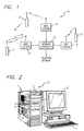
- FIG. 1 shows a cellular communication system 10 including a plurality of subscriber units 12 such as cellular telephones, fax machines and personal computers 13 according to the present invention.
- the system 10 also includes a number of base stations 14 that allow the subscriber units 12 to communicate with each other and with other communication devices in other networks.
- the system 10 covers a geographical area that is divided into a grid of cell sites, with each cell site containing at least one base station 14.
- Each base station 14 communicates with all subscriber units 12 in its cell site via radio frequency (“RF") signals.
- RF radio frequency
- One frequency is used for transmission from the base station 14 to the subscriber units 12 (the “downlink” frequency), and a different frequency is used for transmission from the subscriber units 12 to the base station 14 (the “uplink” frequency).
- the system 10 employs "frequency reuse" to allow more than one base station 14 to operate at the same radio frequency.
- Each cell site is made large enough so that RF signals crossing a cell site are attenuated in substantial amount so that they are perceived as lower level noise by base stations in distant cell sites. Frequency isolation occurs in free space because the RF signals are inherently attenuated in proportion to the square of the distance from the radiating source. Isolation is furthered by interference arising from man-made and natural structures.
- One or more frequencies are set aside for setting up a communication link or call between the base station 14 and a subscriber unit 12.
- the base stations 14 are interlinked with a network controller 16 via a distribution facility such as a dedicated copper wire or fiber optic network, a radio communication link, or a satellite link.
- the satellite link provides the highest system capacity.
- the network controller 16 provides access to existing wireline telephone networks.
- Each base station 14 determines the received signal strength of each call in progress, and forwards this information to the network controller 16.
- the network controller 16 uses advanced processing technology to keep track of all calls between the subscriber units 12 and base stations 14.
- the network controller 16 also uses the signal strength information from each base station 14 to determine when a call should be "handed off" from the base station in one cell site to the base station in another cell site. Hand-off allows communication to be maintained with a subscriber unit 12 as the subscriber unit 12 roams from cell site to cell site.
- Video, audio and data are transmitted over the airwaves as digital signals between the subscriber units 12 and base stations 14.
- Sources of video, audio and data are not limited to other subscriber units 12 in the system 10. Since the base stations 14 are linked to telephone networks, data can be provided over wired networks by sources such as private faxes and corporate computers containing commercial databases. Audio can be provided over wired networks by analog telephones, personal computers and even radios. Video can be provided by direct broadcast satellites and Very Small Aperture Terminals, and by computers over fiber optic and ISDN networks.
- each frequency bandwidth is "shared" by all subscriber units 12, either through a Time Division Multiple Access (“TDMA”) technique or a Code Division Multiple Access (“CDMA”) technique.
- TDMA Time Division Multiple Access
- CDMA Code Division Multiple Access
- the TDMA technique divides up the total bandwidth into a predetermined number of time slots, with each subscriber unit 12 being allocated a specific time slot. One of the time slots contains an imbedded control channel.
- Each base station 14 continuously transmits time division multiplexed bit streams to the subscriber units 12 on the downlink frequency, with each subscriber unit 12 responding by transmitting bursts on the uplink frequency. Even if a base station 14 is not communicating with a subscriber unit 12, a dummy time slot transmission is sent.
- the CDMA technique instead of dividing up the total bandwidth into time slots, spreads the signal of each subscriber unit 12 across the entire bandwidth.
- each subscriber unit 12 generally occupies the entire bandwidth designated by the base station 14, it utilizes only a portion of the power available to the base station 14.
- the information-bearing signal is multiplied by a high bandwidth, high frequency digital spreading signal, which expands the narrow bandwidth information-bearing signal into a broad spread signal covering the entire transmission bandwidth.
- the spreading signal uses quasi-orthogonal bit sequences of period Tc, referred to in the art as chips.
- the chip sequence causes the cross-correlation function between subscriber units 12 to be small, in which event the subscriber units 12 are quasi-orthogonal to each other.
- the chip sequence can be generated or chosen so that a predetermined or unique chip sequence is assigned to a specific subscriber unit 12 during the call set up each time the subscriber unit 12 starts a call. This, of course, requires the network controller 16 to maintain a central log or listing of all user chip sequence assignments.
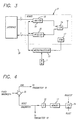
- FIG. 2 shows the personal computer 13 according to the present invention.
- the computer 13 includes a tower 1 for housing a motherboard 2, which includes a microprocessor, Random Access Memory (RAM), BIOS, cache and expansion bus slots.
- the microprocessor can be a "PENTIUM” processor, a RISC-based processor (e.g., MIPS, "PowerPC") or a more powerful processor.
- the tower 1 also includes a hard disk drive 3, and peripherals such a CD ROM drive 4 and a floppy disk drive 5.
- a keyboard 7 provides basic input commands to the computer, and video is output over a display 8.
- the tower 1 further includes a backplate 6 for accommodating expansion boards and cards such as internal modem cards, graphics accelerator boards, video capture cards, and sound cards. The expansion boards and cards are connected to the expansion slots.
- Audio signals can be supplied to the sound card by a hand held microphone and they can be outputted from the sound card to a speaker system.
- Video signals can be supplied to the video capture card by a hand held camera. The video images from the camera are quantized by the video capture card in both the spatial domain and the intensity domain.
- the backplate 6 also accommodates a wireless communications board 9 for allowing the computer 13 to communicate over the airwaves.
- the wireless communications board 9 includes a Read Only Memory (ROM) 17, transmitter 18, receiver 20, T/R module 24 and a high efficiency antenna 26.
- the ROM 17 stores an application program for the microprocessor 22. When programmed by the ROM 17, the microprocessor 22 defines and implements the protocol for the computer 13. In an alternative embodiment, the application program could be stored on one of the computer's storage devices, such as the hard disk. This would eliminate the need for the ROM 17.
- the protocol defines the convention through which the personal computer 13 can communicate with the base station 14.
- the microprocessor 22 decodes the header of each base station transmission and executes a protocol structure which controls timing and decision making logic instructions (e.g., timing, message slot selection, T/R control) and other well known operations.
- the computer 13 Prior to a call setup, the computer 13 monitors air time, activity, account numbers, and protocol of the base station 14 to determine whether it can access the system 10.
- the computer 13 When the computer 13 is ready to make a call, or when a call is transmitted to it, the computer 13 establishes a setup channel with a proximate base station 14.
- the base station 14 specifies the unique time slots and uplink/downlink frequencies for the computer 13 to transmit and receive the call.
- the microprocessor 22 allocates the RF bandwidth among the audio, video and data signals.
- Bandwidth is allocated by varying the compression rates of the audio and video signals.
- the compression rates are dynamically varied to allow as much audio and video as possible to be transmitted within their allocated bandwidths.
- the audio compression rate is decreased, the bandwidth of the audio is increased and the bandwidth of the video is decreased.
- audio fidelity is improved and video quality is degraded.
- the audio compression rate is increased, the audio bandwidth is decreased and the video bandwidth is increased. This results in an improvement of the video quality and a degradation of the audio fidelity.
- the personal computer 13 automatically performs the bandwidth allocation in response to a request from another party on the communication link. If the other party desires a higher quality audio, it sends an appropriate request to the personal computer 13. The personal computer 13 responds by decreasing the audio compression rate to improve the quality of the audio being transmitted to the other party. If it is desired for the personal computer 13 to receive higher quality video, an input for lower sound fidelity is made by using an input device such as the keyboard 7, and the personal computer 13 transmits the request for lower audio fidelity to the other party.
- This protocol two bits in a transmission header are dedicated to the request. The two bits represent four possible conditions: audio increase, audio decrease, no change in audio, and preset audio.
- the microprocessor 22 constantly checks for requests from the other party by monitoring the transmission headers received during the communication link.
- the personal computer 13 receives a request, its microprocessor 22 determines the appropriate bandwidths for the audio and video signals.
- the transmitter 18 compresses the audio and video signals. Following compression, audio, video and data signals are broken up into transport packets and multiplexed together with the transmission header (which includes the two-bit request) to form a composite signal.
- the composite signal is further processed by the transmitter 18 into either a spread spectrum signal or a time division multiplexed signal, depending upon whether CDMA or TDMA is being used by the system 10.
- the encoded signal is used to modulate a carrier signal.
- the modulated carrier signal is sent to the antenna 26 through the T/R module 24.
- only audio and data signals are multiplexed with the header to form the composite signal, with compression being performed on the audio signal only.
- RF signals received on the antenna 26 are sent to the receiver 20 through the T/R module 24.
- the receiver 20 separates the incoming signal into four demodulated signals: a compressed video signal, a compressed audio signal, a data signal and a transmission header.
- the transmission header is sent to the microprocessor 22 and monitored for a request to increase audio fidelity.
- the compressed video signal, compressed audio signal and the data signal are unformatted.
- the compressed signals are then decompressed using compression rates embedded in the compressed signals.
- the decompressed signals, along with the unformatted data signal, are forwarded to the appropriate interfaces 28 in the personal computer 13.
- a VGA-based CRT can display 640 horizontal by 480 vertical pixels (640 x 480).
- CRTs typically have a set of three phosphors -- red, green and blue -- at each pixel location. This allows each pixel to display a gamut of colors falling within a three dimensional cube. Colors at the eight vertices of the cube are black, white, red, green, blue, cyan, magenta and yellow. Colors within the cube are produced by mixtures of various intensities of red, green, and blue. Digital words representing the colors are converted to an analog video signal, which causes an electron gun to illuminate the phosphors of the CRT, thereby creating light.
- Color resolution is equivalently measured by the number of data bits for storing each pixel of the image in a computer's video memory.
- the display of "true color” would requires a bit length of 24 bits.
- the amount of video information would be enormous.
- the amount of video information is drastically reduced by limiting the bit length to 8-bits and using a simulation technique to simulate the true colors of an image.
- Pixel words of 8-bit can display 256 colors simultaneously, and the simulation technique can be used to simulate many of the 16 million colors offered by 24-bit resolution.
- One approach for simulating the true colors is to employ a color palette or lookup table containing an optimal selection of colors.
- the palette contains those colors which occur most frequently in the image being reproduced. For 8-bit color resolution reproductions, the 256 colors used most frequently in the image are be chosen to fill the color palette.
- each color in the video image is mapped to the nearest color in the palette.
- the quality of the resulting image is improved since the true color of most of the image's pixels will be in the palette.
- Dithering aims to sacrifice some of an image's spatial resolution for an increase in perceived intensity resolution, which is accomplished by averaging the intensities of several neighboring pixels to simulate intensities that lie between quantization levels.
- dithering techniques relies on the eye's ability to blend the colors of adjacent pixels over small spatial areas so that an intermediate color is perceived. This approach focuses on replacing or mapping non-displayable colors (those not in the displayable color palette) within defined areas of the image to displayable colors to best simulate the true color when viewed by the human eye.
- the neighborhoods are chosen according to a two dimensional set of values, referred to as the dither table or dither matrix, which is tiled into the image's coordinate space.
- the values contained in the table are used to make decisions about which quantized intensity value will be output at each position, that is, should the intensity value be quantized to the quantized value above or below the original intensity value.
- the dither table values are different at each coordinate location such that when a constant input intensity is dithered over some area, the output values will alternate in some pattern between the upper and lower quantized intensity levels.
- the above techniques were used to reduce memory requirements of the display system.
- the above techniques are used to reduce the number of transmitted video bits.
- the video information can be minimized, yet "true color" quality of the video image can still be maintained.
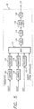
- FIG. 4 shows the logic executed by the microprocessor 22 for the dynamic allocation of the RF bandwidth among the video and audio signals.
- the logic includes a summing junction 30 for generating an error signal ERR indicating the difference between the RF bandwidth and the audio bandwidth.
- the error signal ERR is, of course, equal to the video bandwidth, the available bandwidth for video signal.
- the error signal ERR is supplied to a video compression module in the transmitter 18, which compresses the video signal until the video signal fits within the video bandwidth.
- the audio bandwidth is also supplied to the transmitter 18.
- the transmitter 18 compresses the audio signal until it fits within the audio bandwidth.
- the RF bandwidth is an a priori value that can be hardwired to the summing junction 30.
- the audio bandwidth is supplied to the summing junction 30 via a latch 32.
- An input of the latch 32 is coupled to the ROM 17, which stores a number of different values indicating different audio bandwidths for the audio signal.
- the bandwidth values are stored in the ROM 17 during manufacture. If a ROM 17 is not employed, and the application program is stored on the hard drive, the bandwidth values can be reprogrammed by the user.
- bandwidth pairs could be stored in the ROM. Each pair includes an audio bandwidth and a video bandwidth. The video and audio bandwidths selected pair are supplied to the transmitter 18.
- the bandwidth value supplied to the latch 32 by the ROM 17 is selected by a counter 34, which indexes the ROM 17. Assume that the bandwidth values are stored in consecutive addresses in the ROM 17, and that the values increase as the addresses increase. Incrementing the counter 34 causes the ROM 17 to output a greater bandwidth value. As the value stored in the latch 32 is increased, the error signal ERR and, therefore, the available bandwidth for video signal are decreased. As a result, video quality is decreased. Decrementing the count results in a lower bandwidth value to be supplied to the latch 32 by the ROM 17. As the bandwidth value stored in the latch 32 is decreased, the error signal ERR and, therefore, the available bandwidth for the video signal are increased.
- the counter 34 can be reset to a preset value. This allows the audio bandwidth to be preset at any time during a call.
- Requests to increment and decrement the counter 34 are supplied to an input of the counter 34.
- the requests are derived from the two-bit request of the transmission header.
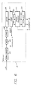
- FIG. 5 shows the functions performed by the transmitter 18.
- the digital video signal is compressed according to an algorithm that supports variable rate compression (block 102).
- the digital audio signal is also compressed according to an algorithm that supports variable rate compression (block 104).
- the video and audio signals are compressed until they fit within the video and audio bandwidths that are allocated by the microprocessor 22.
- the compressed video signal is broken up into video transport packets (block 106), and the audio signal is broken up into audio transport packets (block 108).
- the data signal although not compressed, is broken up into data transport packets (block 110).
- Each transport packet includes a header and data portion. In the case of the compressed signals, the header will indicate whether the compression rates are stored in the first few bytes of the data portion.
- Apparatus and methods for compressing the audio and video signals are disclosed in U.S. Serial No. 08/ , filed herewith (Attorney Docket No. P-2816) and incorporated herein by reference.
- the apparatus supports variable rate compression and utilizes multiple compression algorithms.
- the apparatus can use an MPEG-1 algorithm for both audio and video compression.
- the same apparatus can use an MPEG-2 algorithm for video compression and Dolby AC3 for audio compression.
- the microprocessor 22 could be programmed to perform the compression on the audio and videos signals.
- the microprocessor 22 could also be programmed to break up the data signal and the compressed signals into transport packets.
- the audio, video and data transport packets are multiplexed together with the transmission header to form a composite signal (block 112).
- the transmission header which is generated by the microprocessor 22, includes the two bits that request the other party to change the bandwidth of the audio signal being transmitted by that party.
- the composite signal is then modulated using phase shift keying (PSK) modulation, frequency shift keying (FSK) modulation, or any other type of modulation suitable for a TDMA or CDMA system (block 114).
- PSK modulation may be any of binary phase shift keying (BPSK) modulation, quadrature phase shift keying (QPSK) modulation, M-ary phase shift keying (MPSK) modulation where M is larger than four, or variants of differential phase shift keying (DPSK) modulation.
- BPSK binary phase shift keying
- QPSK quadrature phase shift keying
- MPSK M-ary phase shift keying
- DPSK differential phase shift keying
- LPC Linear Predictive Coding
- CVSD Continuously Variable Sloped Delta
- the digitally encoded information signal is mixed with a spreading chip sequence, which is assigned to the subscriber unit (block 118).
- the chip sequence is sent by the subscriber unit to the base station 14 as part of the call setup. It is desirable to spread the communication signal to cover the entire allocated bandwidth where possible and achieve a high processing gain.
- the mixed broad band spread information signal is then mixed with a carrier frequency to produce the communication signals to be transmitted (block 120).
- the specific frequency used is predetermined by the spectral allocation for the communication system 10.
- the modulated signal is sent to the T/R module 24, which transmits the signal under the control of the microprocessor 22.
- the digitally encoded information signal is used to modulate a carrier frequency only during the allocated time slot (blocks 112 and 114).
- the resulting burst is transmitted by the T/R module.
- FIG. 6 shows the functions performed by the receiver 20.
- the receiver 20 performs low noise amplification on the signal received from the antenna and T/R module and down converts the amplified signal into an intermediate frequency (IF) signal (block 202).
- IF intermediate frequency
- Gain control of the IF signal is performed and the gain-controlled IF signal is mixed to form a baseband signal (block 204).
- the baseband signal is then locked onto and demodulated by breaking it into its in-phase (I) and quadrature (Q) components, which are converted into a digital signal (block 206).
- the digital signal is deinterleaved and decoded at a predetermined decoding rate by a convolutional decoder such as a Viterbi algorithm decoder (block 208).
- a convolutional decoder such as a Viterbi algorithm decoder
- the decoded signal is then demultiplexed into a header signal and video, audio and data transport packets (block 210).
- the transmission header is supplied to the microprocessor 22 and the audio, data and video signals are sent to an inverse transport processor (block 212).
- the compressed audio and video signals are thereafter decompressed using the audio and video compression rates embedded in the data portion of the transport packet (block 214).
- the decompressed video and audio signals are synchronized and then forwarded, along with the unformatted data signal, to the appropriate interfaces.
- an RF communication system that overcomes the problem of bandwidth limitations associated with the transmission of audio and high quality video signals.
- the problem is overcome by dynamically allocating the bandwidth among the audio and video signals.
- Still further disclosed is computer that can communicate over the airwaves. Still further disclosed is a method for configuring existing computers to communicate over the airwaves.
- the microprocessor can use video bandwidth as the controlling parameter instead of audio bandwidth.
- the invention can be applied not only to the personal computer disclosed herein, but to the personal computer described in U.S. Serial No. 08/ , filed herewith (Attorney Docket No. 114-224), which is incorporated herein by reference.
- the invention is not restricted to personal computers, and could be applied to other types of general purpose computers (e.g., workstations) and computers dedicated to specific purposes (e.g.,web browsers).
- use of the invention is not limited to CDMA and TDMA communication systems, but can be applied to any other type of narrow bandwidth communications system. Accordingly, the present invention is not limited to the precise embodiment described hereinabove.
Landscapes
- Engineering & Computer Science (AREA)
- Signal Processing (AREA)
- Multimedia (AREA)
- Computer Networks & Wireless Communication (AREA)
- Compression Or Coding Systems Of Tv Signals (AREA)
- Picture Signal Circuits (AREA)
- Compression Of Band Width Or Redundancy In Fax (AREA)
- Mobile Radio Communication Systems (AREA)
- Reduction Or Emphasis Of Bandwidth Of Signals (AREA)
Applications Claiming Priority (2)
| Application Number | Priority Date | Filing Date | Title |
|---|---|---|---|
| US581676 | 1995-12-29 | ||
| US08/581,676 US5729535A (en) | 1995-12-29 | 1995-12-29 | Method and apparatus for adapting a computer for wireless communications |
Publications (2)
| Publication Number | Publication Date |
|---|---|
| EP0783232A2 true EP0783232A2 (fr) | 1997-07-09 |
| EP0783232A3 EP0783232A3 (fr) | 1999-02-17 |
Family
ID=24326121
Family Applications (1)
| Application Number | Title | Priority Date | Filing Date |
|---|---|---|---|
| EP96309338A Withdrawn EP0783232A3 (fr) | 1995-12-29 | 1996-12-20 | Méthode et appareil pour adapter un ordinateur à une communication sans fil |
Country Status (3)
| Country | Link |
|---|---|
| US (1) | US5729535A (fr) |
| EP (1) | EP0783232A3 (fr) |
| JP (1) | JPH09200863A (fr) |
Cited By (3)
| Publication number | Priority date | Publication date | Assignee | Title |
|---|---|---|---|---|
| WO1998034378A1 (fr) * | 1997-01-31 | 1998-08-06 | Sharewave, Inc. | Procede et appareil permettant d'incorporer un equipement dans un systeme informatique |
| US6282714B1 (en) | 1997-01-31 | 2001-08-28 | Sharewave, Inc. | Digital wireless home computer system |
| WO2009045905A2 (fr) * | 2007-09-28 | 2009-04-09 | Qualcomm Incorporated | Procédés et systèmes de compression/décompression d'en-tête solides |
Families Citing this family (30)
| Publication number | Priority date | Publication date | Assignee | Title |
|---|---|---|---|---|
| US9832244B2 (en) * | 1995-07-14 | 2017-11-28 | Arris Enterprises Llc | Dynamic quality adjustment based on changing streaming constraints |
| GB2304502B (en) * | 1995-08-23 | 1999-10-06 | Plessey Telecomm | Multiplexing/demultiplexing method |
| US6044199A (en) * | 1996-09-25 | 2000-03-28 | Sony Corporation | Authoring system and the method |
| US6456607B2 (en) * | 1996-10-16 | 2002-09-24 | Canon Kabushiki Kaisha | Apparatus and method for transmitting an image signal modulated with a spreading code |
| US6128484A (en) * | 1997-10-07 | 2000-10-03 | International Business Machines Corporation | Wireless transceivers for remotely controlling a computer |
| FI104925B (fi) * | 1997-10-31 | 2000-04-28 | Nokia Networks Oy | Kanavointimenetelmä ja lähetinvastaanotin |
| US6373855B1 (en) * | 1998-03-05 | 2002-04-16 | Intel Corporation | System and method for using audio performance to control video bandwidth |
| US7079778B1 (en) * | 2000-04-07 | 2006-07-18 | Northrop Grumman Corporation | Rugged shock-resistant backplane for embedded systems |
| DE19933814A1 (de) * | 1999-07-20 | 2001-01-25 | Abb Research Ltd | Verfahren und Anordnung zur drahtlosen Informationsübertragung sowie Informationssystem für eine eine Vielzahl von Sensoren und/oder Aktoren aufweisende Maschine |
| CA2382128A1 (fr) * | 1999-08-27 | 2001-03-08 | Nokia Corporation | Terminal multimedia mobile pour la diffusion video numerique |
| US7827581B1 (en) | 2000-02-29 | 2010-11-02 | BE Labs, Inc. | Wireless multimedia system |
| US6898378B1 (en) * | 2000-03-24 | 2005-05-24 | Northrop Grumman Corporation | Shock-resistant backplane utilizing infrared communication scheme with electrical interface for embedded systems |
| US6845104B2 (en) * | 2000-06-14 | 2005-01-18 | Ipr Licensing, Inc. | Receiver for time division multiplex system without explicit time slot assignment |
| US7630721B2 (en) | 2000-06-27 | 2009-12-08 | Ortiz & Associates Consulting, Llc | Systems, methods and apparatuses for brokering data between wireless devices and data rendering devices |
| US7812856B2 (en) | 2000-10-26 | 2010-10-12 | Front Row Technologies, Llc | Providing multiple perspectives of a venue activity to electronic wireless hand held devices |
| US7039116B1 (en) * | 2000-11-07 | 2006-05-02 | Cisco Technology, Inc. | Methods and apparatus for embedding and format conversion of compressed video data |
| US6847622B1 (en) * | 2000-11-15 | 2005-01-25 | Motorola, Inc. | Methods and apparatus for providing multiple wireless communication services having different bit rates |
| US20040181806A1 (en) * | 2003-03-11 | 2004-09-16 | Visual Circuits Corporation | Method and apparatus for transmitting digital video signals in a digital visual interface format over an RF cable |
| US7599002B2 (en) * | 2003-12-02 | 2009-10-06 | Logitech Europe S.A. | Network camera mounting system |
| US20050120128A1 (en) * | 2003-12-02 | 2005-06-02 | Wilife, Inc. | Method and system of bandwidth management for streaming data |
| JP2006270576A (ja) * | 2005-03-24 | 2006-10-05 | Matsushita Electric Ind Co Ltd | 通信端末及びネットワーク制御装置 |
| US8189621B2 (en) | 2006-05-12 | 2012-05-29 | Microsoft Corporation | Stack signaling to application with lack of requested bandwidth |
| US8144793B2 (en) | 2006-12-12 | 2012-03-27 | Microsoft Corporation | Cognitive multi-user OFDMA |
| KR100827119B1 (ko) * | 2006-12-13 | 2008-05-06 | 삼성전자주식회사 | 입체 영상 서비스 시스템 및 방법과 입체 영상 생성 장치 및 입체 영상 출력장치 |
| US8139487B2 (en) | 2007-02-28 | 2012-03-20 | Microsoft Corporation | Strategies for selecting a format for data transmission based on measured bandwidth |
| US7929623B2 (en) | 2007-03-30 | 2011-04-19 | Microsoft Corporation | FEC in cognitive multi-user OFDMA |
| US7970085B2 (en) | 2007-05-08 | 2011-06-28 | Microsoft Corporation | OFDM transmission and reception for non-OFDMA signals |
| US8374130B2 (en) * | 2008-01-25 | 2013-02-12 | Microsoft Corporation | Orthogonal frequency division multiple access with carrier sense |
| US9035992B1 (en) | 2013-04-08 | 2015-05-19 | Google Inc. | Bandwidth modulation system and method |
| US9832500B2 (en) * | 2014-07-05 | 2017-11-28 | TiltedGlobe LLC | System for enabling a virtual theater |
Family Cites Families (11)
| Publication number | Priority date | Publication date | Assignee | Title |
|---|---|---|---|---|
| US5231492A (en) * | 1989-03-16 | 1993-07-27 | Fujitsu Limited | Video and audio multiplex transmission system |
| US5347305A (en) * | 1990-02-21 | 1994-09-13 | Alkanox Corporation | Video telephone system |
| US5374963A (en) * | 1990-06-01 | 1994-12-20 | Thomson Consumer Electronics, Inc. | Picture resolution enhancement with dithering and dedithering |
| US5343513A (en) * | 1992-04-20 | 1994-08-30 | Hughes Aircraft Company | Channel compression and dynamic repartitioning for dual mode cellular radio |
| US5541640A (en) * | 1992-06-23 | 1996-07-30 | Larson; Craig R. | Videophone for simultaneous audio and video communication via a standard telephone line |
| JP2774906B2 (ja) * | 1992-09-17 | 1998-07-09 | 三菱電機株式会社 | 薄形半導体装置及びその製造方法 |
| KR950704901A (ko) * | 1992-12-17 | 1995-11-20 | 롱긴 오우, 루카스 | 유효 정보전달비를 증가시키기 위한 정보전달시스템(an information transmission system for increasing the effective rate of transfer of information) |
| AU7095294A (en) * | 1993-06-08 | 1995-01-03 | Mitsui Comtek Corporation | Pcmcia cellular card adaptable to a portable computer or a cellular phone handset |
| US5461619A (en) * | 1993-07-06 | 1995-10-24 | Zenith Electronics Corp. | System for multiplexed transmission of compressed video and auxiliary data |
| US5526350A (en) * | 1994-03-09 | 1996-06-11 | British Telecommunications Public Limited Company | Communication network with bandwidth managers for allocating bandwidth to different types of traffic |
| US5548532A (en) * | 1994-04-28 | 1996-08-20 | Thomson Consumer Electronics, Inc. | Apparatus and method for formulating an interactive TV signal |
-
1995
- 1995-12-29 US US08/581,676 patent/US5729535A/en not_active Expired - Lifetime
-
1996
- 1996-12-20 EP EP96309338A patent/EP0783232A3/fr not_active Withdrawn
- 1996-12-27 JP JP8350048A patent/JPH09200863A/ja active Pending
Non-Patent Citations (1)
| Title |
|---|
| None |
Cited By (7)
| Publication number | Priority date | Publication date | Assignee | Title |
|---|---|---|---|---|
| WO1998034378A1 (fr) * | 1997-01-31 | 1998-08-06 | Sharewave, Inc. | Procede et appareil permettant d'incorporer un equipement dans un systeme informatique |
| US6243772B1 (en) | 1997-01-31 | 2001-06-05 | Sharewave, Inc. | Method and system for coupling a personal computer with an appliance unit via a wireless communication link to provide an output display presentation |
| US6282714B1 (en) | 1997-01-31 | 2001-08-28 | Sharewave, Inc. | Digital wireless home computer system |
| WO2009045905A2 (fr) * | 2007-09-28 | 2009-04-09 | Qualcomm Incorporated | Procédés et systèmes de compression/décompression d'en-tête solides |
| WO2009045905A3 (fr) * | 2007-09-28 | 2009-06-04 | Qualcomm Inc | Procédés et systèmes de compression/décompression d'en-tête solides |
| US8199663B2 (en) | 2007-09-28 | 2012-06-12 | Qualcomm Incorporated | Robust header compression/decompression methods and systems |
| US8509111B2 (en) | 2007-09-28 | 2013-08-13 | Qualcomm Incorporated | Robust header compression/decompression methods and systems |
Also Published As
| Publication number | Publication date |
|---|---|
| US5729535A (en) | 1998-03-17 |
| JPH09200863A (ja) | 1997-07-31 |
| EP0783232A3 (fr) | 1999-02-17 |
Similar Documents
| Publication | Publication Date | Title |
|---|---|---|
| US5729535A (en) | Method and apparatus for adapting a computer for wireless communications | |
| US5793416A (en) | Wireless system for the communication of audio, video and data signals over a narrow bandwidth | |
| US6111863A (en) | Method and apparatus for the dynamic allocation of signal bandwidth between audio, video and data signals | |
| US5210771A (en) | Multiple user spread-spectrum communication system | |
| US5781856A (en) | Concentrated subscriber system for wireless local loop | |
| US7426241B2 (en) | Variable rate coding for forward link | |
| US7929494B1 (en) | High-speed data transmission in a digital mobile communication system | |
| US9306658B2 (en) | Method and apparatus for a spectrally compliant cellular communication system | |
| CN107708167B (zh) | 可自适应切换宽窄带通信的终端、系统及其通信方法 | |
| US5809243A (en) | Personal interface system for wireless and wired communications | |
| JPH05130082A (ja) | 可変変調通信方式 | |
| CN1334664A (zh) | 无线通信设备 | |
| CA2382128A1 (fr) | Terminal multimedia mobile pour la diffusion video numerique | |
| KR20110099003A (ko) | 단일 변조 계획을 갖는 중첩 코드화된 멀티캐스트용 시스템, 방법 및 컴퓨터 프로그램 | |
| EP0878924B1 (fr) | Système de communication à accès multiples à division temporelle | |
| US6545990B1 (en) | Method and apparatus for a spectrally compliant cellular communication system | |
| JPH05336061A (ja) | 移動無線システム | |
| US5202755A (en) | Encoding system of a simulcast high definition television and method thereof | |
| CA2330184A1 (fr) | Systeme radio mobile de telecommunications assurant un service video en temps reel | |
| JPH0923207A (ja) | 情報多重化方式 | |
| JPH0738944A (ja) | 移動通信回線設定方法 | |
| JP2000106537A (ja) | 衛星基地局、可搬型衛星端末局間の通信チャネル多重化装置 |
Legal Events
| Date | Code | Title | Description |
|---|---|---|---|
| PUAI | Public reference made under article 153(3) epc to a published international application that has entered the european phase |
Free format text: ORIGINAL CODE: 0009012 |
|
| AK | Designated contracting states |
Kind code of ref document: A2 Designated state(s): DE FR GB IT NL |
|
| PUAL | Search report despatched |
Free format text: ORIGINAL CODE: 0009013 |
|
| AK | Designated contracting states |
Kind code of ref document: A3 Designated state(s): DE FR GB IT NL |
|
| STAA | Information on the status of an ep patent application or granted ep patent |
Free format text: STATUS: THE APPLICATION IS DEEMED TO BE WITHDRAWN |
|
| 18D | Application deemed to be withdrawn |
Effective date: 19990818 |