EP0783085B1 - Piece souple susceptible d'être montée dans une ouverture - Google Patents
Piece souple susceptible d'être montée dans une ouverture Download PDFInfo
- Publication number
- EP0783085B1 EP0783085B1 EP19960402914 EP96402914A EP0783085B1 EP 0783085 B1 EP0783085 B1 EP 0783085B1 EP 19960402914 EP19960402914 EP 19960402914 EP 96402914 A EP96402914 A EP 96402914A EP 0783085 B1 EP0783085 B1 EP 0783085B1
- Authority
- EP
- European Patent Office
- Prior art keywords
- lip
- wall
- gripping
- mounting
- part according
- Prior art date
- Legal status (The legal status is an assumption and is not a legal conclusion. Google has not performed a legal analysis and makes no representation as to the accuracy of the status listed.)
- Expired - Lifetime
Links
- 230000007704 transition Effects 0.000 claims description 16
- 239000000463 material Substances 0.000 claims description 10
- 239000012528 membrane Substances 0.000 claims description 8
- 238000007789 sealing Methods 0.000 claims description 8
- 238000012423 maintenance Methods 0.000 description 3
- 239000013013 elastic material Substances 0.000 description 2
- 229920001971 elastomer Polymers 0.000 description 2
- 239000000806 elastomer Substances 0.000 description 2
- 239000012530 fluid Substances 0.000 description 2
- 239000000446 fuel Substances 0.000 description 2
- 235000019589 hardness Nutrition 0.000 description 2
- 238000007689 inspection Methods 0.000 description 2
- 238000004519 manufacturing process Methods 0.000 description 2
- 238000000034 method Methods 0.000 description 2
- 238000004078 waterproofing Methods 0.000 description 2
- 229920002943 EPDM rubber Polymers 0.000 description 1
- 229920002449 FKM Polymers 0.000 description 1
- 238000009434 installation Methods 0.000 description 1
- 230000002093 peripheral effect Effects 0.000 description 1
- 239000011435 rock Substances 0.000 description 1
- 229920001169 thermoplastic Polymers 0.000 description 1
- 239000004416 thermosoftening plastic Substances 0.000 description 1
Images


Classifications
-
- F—MECHANICAL ENGINEERING; LIGHTING; HEATING; WEAPONS; BLASTING
- F16—ENGINEERING ELEMENTS AND UNITS; GENERAL MEASURES FOR PRODUCING AND MAINTAINING EFFECTIVE FUNCTIONING OF MACHINES OR INSTALLATIONS; THERMAL INSULATION IN GENERAL
- F16L—PIPES; JOINTS OR FITTINGS FOR PIPES; SUPPORTS FOR PIPES, CABLES OR PROTECTIVE TUBING; MEANS FOR THERMAL INSULATION IN GENERAL
- F16L5/00—Devices for use where pipes, cables or protective tubing pass through walls or partitions
- F16L5/02—Sealing
- F16L5/10—Sealing by using sealing rings or sleeves only
-
- F—MECHANICAL ENGINEERING; LIGHTING; HEATING; WEAPONS; BLASTING
- F16—ENGINEERING ELEMENTS AND UNITS; GENERAL MEASURES FOR PRODUCING AND MAINTAINING EFFECTIVE FUNCTIONING OF MACHINES OR INSTALLATIONS; THERMAL INSULATION IN GENERAL
- F16L—PIPES; JOINTS OR FITTINGS FOR PIPES; SUPPORTS FOR PIPES, CABLES OR PROTECTIVE TUBING; MEANS FOR THERMAL INSULATION IN GENERAL
- F16L41/00—Branching pipes; Joining pipes to walls
- F16L41/08—Joining pipes to walls or pipes, the joined pipe axis being perpendicular to the plane of a wall or to the axis of another pipe
- F16L41/088—Joining pipes to walls or pipes, the joined pipe axis being perpendicular to the plane of a wall or to the axis of another pipe fixed using an elastic grommet between the extremity of the tube and the wall
-
- F—MECHANICAL ENGINEERING; LIGHTING; HEATING; WEAPONS; BLASTING
- F16—ENGINEERING ELEMENTS AND UNITS; GENERAL MEASURES FOR PRODUCING AND MAINTAINING EFFECTIVE FUNCTIONING OF MACHINES OR INSTALLATIONS; THERMAL INSULATION IN GENERAL
- F16L—PIPES; JOINTS OR FITTINGS FOR PIPES; SUPPORTS FOR PIPES, CABLES OR PROTECTIVE TUBING; MEANS FOR THERMAL INSULATION IN GENERAL
- F16L55/00—Devices or appurtenances for use in, or in connection with, pipes or pipe systems
- F16L55/10—Means for stopping flow in pipes or hoses
- F16L55/11—Plugs
- F16L55/1141—Plugs the plug being made of elastic material
Definitions
- the present invention relates to a flexible piece likely to be mounted in an opening.
- the invention relates to the mounting of pieces of material flexible to put on a support or in a cutout of a support and in particular the mounting of elements such as seals, sleeves, bellows, sleeves, plugs, cups and other parts to be connected to a wall, on the periphery thereof or in a blind, or through cutout that she presents.
- a piece of flexible and elastic material on a support or in a cutout as well as the pieces of flexible and elastic material, in particular the sleeves, seals, bellows, plugs, cups, sleeves, and others connecting elements for implementing the method.
- FR-A-2 637 351 describes an elastomer part of the type sleeves, bellows, seals, plugs or cups vehicle fuel comprising a body the end of which is provided with a sidewall and a movable lip between a corresponding first folded position on condition before mounting the part, and a second deployed position corresponding to the mounted condition of the part in which the lip forms with said flank a groove for receiving the periphery of a cutout practiced in a wall on which the part is to be mounted.
- the maneuver of assembly or disassembly of the part of FR-A-2 637 351 is carried out by grabbing the lip directly or by an appendage to bring it below or beyond the plane formed by the cutout on which the part is to be mounted.
- the assembly and disassembly of the part according to this Patent requires entering the lip and tilt it beyond the plane of the opening on which the part is to rise.
- This maneuver does not pose any particular problems in the case of fitting the part on an assembly line during the manufacture of a motor vehicle.
- the maneuvers are more difficult to perform during maintenance operations.
- the removal operation workpiece requires hand or tool to pass through opening on which the part is mounted to grip the lip. Disassembly is particularly delicate in the case of small diameter openings.
- the part cannot be fitted with a sealing membrane of the opening on the external side in the blind holes or openings whose internal face can be made inaccessible.
- FR-A-2 637 351 does not describe the position of any membrane or sealing wall. However, if we wanted to equip this room with such a wall or such a membrane, this should necessarily be beyond the deployed position of the lip so as not to interfere the access required for the assembly operation.
- a piece of material flexible with a fixing lip that can take a first stable position corresponding to the condition before mounting or removing the part and a second stable position corresponding to a condition rise of the part in which the lip forms with an element of the part a groove for receiving the periphery of a wall or the like to be fitted, where said part further comprises a foot mechanically connected to said fixing lip as well as to a transition zone, itself connected to a functional element, and where means for gripping and / or operation of the fixing lip are mechanically connected to this lip of so that a force exerted on the gripping means and / or maneuver and transmitted to the transition zone ensures the movement of the fixing lip between these two stable positions.
- the maneuvering gripping means lip are mechanically connected to anchor points regularly distributed over the transition zone mechanically linked to the lip to maneuver.
- the piece has an axis of symmetry and the gripping means and maneuver have ribs extending radially from a point of said axis.
- the piece is a shutter and has a membrane sealing.
- the receiving groove of the periphery of the wall to be fitted is substantially parallel to the waterproofing membrane.
- the transition zone is substantially frustoconical, itself connected to a functional element including a waterproofing membrane.
- the area of transition forms a convex truncated cone in the condition before mounting the part and a concave truncated cone in the assembled condition of the part, and the positions of the functional element in the conditions before mounting and mounting of the part are parallel.
- a force parallel to the axis of the part in the direction of the wall to shoeing moves said piece from condition before fitting to condition climb.
- a force parallel to the axis of the part directed opposite the wall to footwear ensures the passage of the piece from the condition mounted to the condition disassembled or removed.
- the foot has a radially external support zone on the wall to fit opposite a radially internal area of attachment of the lip of fixing, so that traction on the gripping means and maneuver directed parallel to the axis of the part opposite the wall to shoeing, causes, via the transition zone, a bracing of the bearing area on the wall to be fitted and a folding of the fixing lip towards the gripping and maneuvering means.
- the piece has a flexible inextensible link directly or indirectly the means for gripping and maneuvering the lip of fixing, this link having a sufficient length so as not to hinder the deployment of the fixing lip during assembly of the part while being short enough to pull the lip toward its position folded down when dismantling the part.
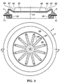
- FIGS. 1 to 5 the same references have been used for designate the same elements.
- FIG. 1 to 3 we can see a first example of production of a part 1 according to the invention, more particularly of a shutter of an opening 3 made in a motor vehicle apron to allow the inspection, maintenance and / or replacement of a sensor, in particular a fuel gauge (not shown).
- the part 1 comprises a foot 7 comprising at least one bearing zone 9 on the periphery of a wall 11, for example on the wall 11 of the deck in which the opening 3 has been made.
- the foot 7 has an axial support zone 9.1 exerting a support force F1 directed towards the bulkhead parallel to an axis 13 of part 1 and a radial support area 9.2 bearing on the surface internal of a falling edge or of a flange 15 situated on the periphery of the opening 3.
- At the foot 7 is fixed, advantageously by zones of low thickness forming hinges 17, a fixing lip 19 provided with a support zone 21.
- the functional element 25 has a sealing and sealing wall airtight opening 3.
- the part 1 according to the invention comprises means 29 for gripping and maneuvering to elastically deform elements of the part 1, so as to allow the deployment of the lip 19 towards the position illustrated in figure 2, with the application of the zone 21 on the wall 11 ensuring the attachment of the part or, at on the contrary, the folding of the lip 19 towards the position illustrated in FIG. 1, allowing the removal of part 1.
- the means 29 of gripping and maneuvering are arranged on the functional element 25 of so that they are easily accessible and can be grasped with your fingers or with pliers.
- the advantageous example illustrates the means 29 for gripping and maneuver comprising at least one, preferably several ribs radials improving the radial rigidity in the two stable conditions of the part, so as to improve the fixing of the part in the opening 3.
- an inextensible link 30 connects the area of transition 23 to the fixing lip 19, so as to facilitate the folding of the latter during the removal operations of the part 1 according to the invention.
- a possible falling edge of the wall 11 forming the collar 15 advantageously improves centering.
- a part 1 according to the present invention, fixed in openings 3 devoid of flanges 15, does not depart from the scope of the present invention.
- the support zone 9.1 is supported on the wall 11 of the deck.
- the force F 2 is transmitted to the transition zone 23 which first stores the elastic energy during the descent to a plane 31 passing through the top of the foot 7 then switches to the stable position illustrated in FIG. 2 corresponding to the mounted condition of the part 1 according to the present invention.
- the descent of the transition zone 23 causes the descent of the lip 19 which rocks around the hinges 17, the support zone 21 coming to bear on the opposite face of the wall 11 to that receiving the support area 9.1 of the foot 7.
- the foot 7 forms with the fixing lip 19 a groove 33 for receiving the end of the wall 11.
- the part 1 in the mounted condition is particularly compact thanks to the descent towards the opening 3 of the functional element 25 and of the means 29 for gripping and maneuver.
- the part 1 is removed by pulling along arrow F 3 opposite arrow F 2 ensuring the deployment of the transition zone 23 and the folding around the hinges 17 of the fixing lip 19, then the withdrawal of the part 1 of opening 3.
- the traction according to arrow F 3 causes the radial expansion of the upper end of the foot according to arrow F 4 which arches on the support zone 9.1 ensuring the folding of the fixing lip 19 according to arrow F 5 .
- the present invention is not limited to plugs and shutters but, within the limits of the claims, also extends to all parts in a flexible material to be fitted over an opening, such as seals, cuffs, bellows, sleeves, cups or the like.
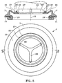
- a functional element 25 comprising means for fasteners of a threaded ring 35 allowing the connection of a connector comprising the adapted thread illustrated in phantom in Figure 5.
- the part central part 1 must have an opening 25 'for fluid passage.
- the means 29 of gripping and maneuvering only have three ribs, so that they do not encroach too much on the passage of the fluids 25 'and do not cause a significant pressure drop.
- the part 1 according to the present invention can be produced in any flexible material, in particular elastomer or material thermoplastic.
- Part 1 can be made of a homogeneous material or may include materials having various hardnesses and rigidities the along its peripheral or radial span.
- the part according to the present invention can have various in particular circular, oval or elliptical shapes and can extend over a left surface corresponding to the shape of the opening 3 that it is intended to put on.
- the part 1 according to the invention is produced in a flexible material whose hardness is between 50 and 80 Shore A. Excellent results have been obtained with parts made of PVC, EPDM and in a material sold by DUPONT DE NEMOURS under the denomination VITON.
- the present invention applies in particular to the boilermaking, to the realization of fittings, joints, and means of connection, and particularly to the automotive industry.
Landscapes
- Engineering & Computer Science (AREA)
- General Engineering & Computer Science (AREA)
- Mechanical Engineering (AREA)
- Cooling, Air Intake And Gas Exhaust, And Fuel Tank Arrangements In Propulsion Units (AREA)
- Gasket Seals (AREA)
Description
- la figure 1 est une vue en coupe longitudinale selon I-I d'un premier exemple de réalisation d'une pièce selon la présente invention avant montage ;
- la figure 2 est une vue en coupe longitudinale selon I-I de la pièce de la figure 1 en condition montée dans une ouverture d'une paroi ;
- la figure 3 comporte une vue en coupe longitudinale et une vue du dessus de la pièce de la figure 1 ;
- la figure 4 est une vue en coupe longitudinale selon IV-IV d'une variante de réalisation de la pièce selon la présente invention en condition montée ;
- la figure 5 comporte une vue en coupe longitudinale et une vue de dessus de la pièce de la figure 4.
Claims (10)
- Pièce en matériau souple comportant une lèvre (19) de fixation pouvant prendre une première position stable correspondant à la condition avant montage ou de dépose de la pièce (1) et une seconde position stable correspondant à une condition montée de la pièce (1) dans laquelle la lèvre (19) forme avec un élément (7) de la pièce (1) une gorge (33) de réception de la périphérie d'une paroi (11) ou analogue à chausser, où ladite pièce comporte en outre, un pied (7) relié mécaniquement à ladite lèvre de fixation (19) ainsi qu'à une zone de transition (23), elle-même reliée à un élément fonctionnel (25), et où des moyens (29) de préhension et/ou de manoeuvre de la lèvre de fixation (19) sont reliés mécaniquement à cette lèvre, ladite pièce caractérisée en ce qu'une force (F2) exercée sur les moyens (29) de préhension et/ou de manoeuvre et transmise à la zone de transition (23) assure le déplacement de la lèvre de fixation (19) entre ces deux positions stables.
- Pièce selon la revendication 1, caractérisée en en ce qu'elle comporte un axe de symétrie (13) et en ce que les moyens de préhension et de manoeuvre comportent des nervures (29) s'étendant radialement à partir d'un point dudit axe (13).
- Pièce selon la revendication 1 ou 2, caractérisée en ce que ladite pièce (1) est un obturateur et en ce qu'elle comporte une membrane d'étanchéité (25).
- Pièce selon la revendication 3, caractérisée en ce que la gorge (33) de réception de la périphérie de la paroi à chausser (11) est sensiblement parallèle à la membrane d'étanchéité (25).
- Pièce selon l'une quelconque des revendications précédentes, caractérisée en ce la zone (23) de transition est sensiblement tronconique.
- Pièce selon la revendication 5, caractérisée en ce que du côté des moyens (29) de préhension et de manoeuvre, la zone de transition (23) forme un tronc de cône convexe dans la condition avant montage de la pièce (1) et un tronc de cône concave dans la condition montée de la pièce (1), et en ce que les positions de l'élément fonctionnel (25) dans les conditions avant montage et montée de la pièce (1) sont parallèles.
- Pièce selon l'une quelconque des revendications 2 à 6, caractérisée en ce qu'une force (F2) parallèle à l'axe (13) de la pièce (1) en direction de la paroi (11) à chausser déplace ladite pièce de la condition avant montage à la condition montée.
- Pièce selon l'une quelconque des revendications 2 à 7, caractérisée en ce qu'une force (F3) parallèle à l'axe (13) de la pièce (1) dirigée à l'opposé de la paroi (11) à chausser assure le passage de la pièce de la condition montée à la condition démontée ou de dépose.
- Pièce selon la revendication 5, 6, 7 ou 8, caractérisée en ce que le pied (7) comporte une zone radialement externe d'appui (9.1) sur la paroi (11) à chausser à l'opposé d'une zone (17) radialement interne d'attache de la lèvre de fixation (19), de manière à ce qu'une traction sur les moyens (29) de préhension et de manoeuvre dirigée parallèlement à l'axe (13) de la pièce (1) à l'opposé de la paroi (11) à chausser, provoque, par l'intermédiaire de la zone de transition (23), un arc-boutement de la zone d'appui (9.1) sur la paroi (11) à chausser et un repliement de la lèvre de fixation (19) en direction des moyens (29) de préhension et de manoeuvre.
- Pièce selon l'une quelconque des revendications précédentes, caractérisée en ce qu'elle comporte un lien inextensible souple (30) reliant directement ou indirectement les moyens (29) de préhension et de manoeuvre à la lèvre de fixation (19), ce lien ayant une longueur suffisante pour ne pas gêner le déploiement de la lèvre de fixation (19) lors du montage de la pièce (1) tout en étant suffisamment courte pour exercer une traction sur la lèvre (19) vers sa position repliée lors du démontage de la pièce (1).
Applications Claiming Priority (2)
| Application Number | Priority Date | Filing Date | Title |
|---|---|---|---|
| FR9600021A FR2743132B1 (fr) | 1996-01-03 | 1996-01-03 | Piece souple susceptible d'etre montee dans une ouverture |
| FR9600021 | 1996-01-03 |
Publications (2)
| Publication Number | Publication Date |
|---|---|
| EP0783085A1 EP0783085A1 (fr) | 1997-07-09 |
| EP0783085B1 true EP0783085B1 (fr) | 2001-10-31 |
Family
ID=9487872
Family Applications (1)
| Application Number | Title | Priority Date | Filing Date |
|---|---|---|---|
| EP19960402914 Expired - Lifetime EP0783085B1 (fr) | 1996-01-03 | 1996-12-27 | Piece souple susceptible d'être montée dans une ouverture |
Country Status (3)
| Country | Link |
|---|---|
| EP (1) | EP0783085B1 (fr) |
| DE (1) | DE69616490T2 (fr) |
| FR (1) | FR2743132B1 (fr) |
Families Citing this family (6)
| Publication number | Priority date | Publication date | Assignee | Title |
|---|---|---|---|---|
| DE19938465B4 (de) * | 1999-08-13 | 2005-02-24 | Valeo Klimasysteme Gmbh | Dichtung |
| DE10310654B4 (de) * | 2003-03-12 | 2005-03-24 | Daimlerchrysler Ag | Manschette |
| ES2342863B1 (es) * | 2007-05-14 | 2011-05-03 | Uralita Sistemas De Tuberias, S.A. | Sistema de saneamiento. |
| JP6682700B2 (ja) | 2017-03-15 | 2020-04-15 | 株式会社水道技術開発機構 | 密栓装置及び密栓方法 |
| EP3611419B1 (fr) * | 2018-08-14 | 2022-03-16 | Wilhelm Ewe GmbH & Co. KG | Manchon de perforation pour une garniture de percage et procédé pour étancher un tube |
| DE102021113927A1 (de) | 2021-05-28 | 2022-12-01 | Wilhelm Ewe GmbH. & Co. Kommanditgesellschaft | Bohrlochabdichthülse für eine Anbohrarmatur und Verfahren zum Abdichten eines Rohres |
Family Cites Families (3)
| Publication number | Priority date | Publication date | Assignee | Title |
|---|---|---|---|---|
| US2756793A (en) * | 1955-03-17 | 1956-07-31 | Earl S Tupper | Storage container lock cover |
| EP0269032B1 (fr) * | 1986-11-21 | 1992-06-03 | Lagan Plast AB | Dispositif de verrouillage à ressort pour un conteneur avec un couvercle |
| FR2637351B1 (fr) * | 1988-09-30 | 1990-12-21 | Hutchinson | Procede de montage d'une piece en materiau souple sur un support et piece pour sa mise en oeuvre |
-
1996
- 1996-01-03 FR FR9600021A patent/FR2743132B1/fr not_active Expired - Fee Related
- 1996-12-27 DE DE1996616490 patent/DE69616490T2/de not_active Expired - Fee Related
- 1996-12-27 EP EP19960402914 patent/EP0783085B1/fr not_active Expired - Lifetime
Also Published As
| Publication number | Publication date |
|---|---|
| FR2743132B1 (fr) | 1998-02-06 |
| EP0783085A1 (fr) | 1997-07-09 |
| DE69616490D1 (de) | 2001-12-06 |
| FR2743132A1 (fr) | 1997-07-04 |
| DE69616490T2 (de) | 2002-05-16 |
Similar Documents
| Publication | Publication Date | Title |
|---|---|---|
| CA2277794C (fr) | Gaine souple universelle a soufflet pour joint articule et outillages de mise en place de cette gaine | |
| FR2562197A1 (fr) | Joint assemble d'etancheite a l'huile et son procede de fabrication | |
| FR2601732A1 (fr) | Dispositif de liaison a separation rapide et application d'un tel dispositif a la realisation de connecteurs a deverrouillage rapide | |
| EP0219418A1 (fr) | Dispositif de raccordement d'un tuyau élastiquement déformable à un tube rigide | |
| EP1612443B1 (fr) | Butée de débrayage et procédé de fabrication | |
| EP0783085B1 (fr) | Piece souple susceptible d'être montée dans une ouverture | |
| FR2527286A1 (fr) | Frein a disque a etrier flottant | |
| EP0561704A1 (fr) | Roulement de butée de suspension pour véhicule et son procédé de montage | |
| EP0737114B1 (fr) | Procede de retreint | |
| WO2009044024A2 (fr) | Ensemble pour collier à griffes, collier et liaison tubulaire correspondants | |
| FR2754024A1 (fr) | Soufflet de transmission pour un vehicule automobile et son procede de remplacement | |
| EP1842271B1 (fr) | Element de paroi pour traversee etanche de cable | |
| EP1540229B1 (fr) | Collier de serrage | |
| FR2975323A1 (fr) | Dispositif pour l'extraction de bague | |
| EP0362067B1 (fr) | Procédé de montage d'une pièce en matériau souple sur un support et pièce pour sa mise en oeuvre | |
| FR2772875A1 (fr) | Dispositif de raccordement d'un tuyau souple a une paroi, en particulier d'un echangeur de chaleur de vehicule automobile | |
| FR2729443A1 (fr) | Soufflet de protection | |
| EP1860362A1 (fr) | Raccord de liaison | |
| EP1388478A1 (fr) | Servomoteur d'assistance pneumatique au freinage et système comportant un maítre-cylindre solidarisé à un tel servomoteur | |
| EP1029182B1 (fr) | Soufflet protecteur pour joint articule d'arbre de transmission | |
| EP0220992B1 (fr) | Dispositif pour désassembler les joints côniques en verrerie | |
| EP2079956B1 (fr) | Dispositif de raccordement rotatif | |
| EP1758220B1 (fr) | Element perfectionne de paroi a traverse etanche | |
| EP1870306A1 (fr) | Servomoteur à tirants comportant une bague d'étanchéité renforcée | |
| WO2020115414A1 (fr) | Soufflet de protection et joint de transmission equipe d'un tel soufflet |
Legal Events
| Date | Code | Title | Description |
|---|---|---|---|
| PUAI | Public reference made under article 153(3) epc to a published international application that has entered the european phase |
Free format text: ORIGINAL CODE: 0009012 |
|
| AK | Designated contracting states |
Kind code of ref document: A1 Designated state(s): DE ES GB IT NL SE |
|
| 17P | Request for examination filed |
Effective date: 19971219 |
|
| 17Q | First examination report despatched |
Effective date: 19991207 |
|
| GRAG | Despatch of communication of intention to grant |
Free format text: ORIGINAL CODE: EPIDOS AGRA |
|
| GRAG | Despatch of communication of intention to grant |
Free format text: ORIGINAL CODE: EPIDOS AGRA |
|
| GRAH | Despatch of communication of intention to grant a patent |
Free format text: ORIGINAL CODE: EPIDOS IGRA |
|
| GRAH | Despatch of communication of intention to grant a patent |
Free format text: ORIGINAL CODE: EPIDOS IGRA |
|
| GRAA | (expected) grant |
Free format text: ORIGINAL CODE: 0009210 |
|
| AK | Designated contracting states |
Kind code of ref document: B1 Designated state(s): DE ES GB IT NL SE |
|
| PG25 | Lapsed in a contracting state [announced via postgrant information from national office to epo] |
Ref country code: NL Free format text: LAPSE BECAUSE OF FAILURE TO SUBMIT A TRANSLATION OF THE DESCRIPTION OR TO PAY THE FEE WITHIN THE PRESCRIBED TIME-LIMIT Effective date: 20011031 Ref country code: IT Free format text: LAPSE BECAUSE OF FAILURE TO SUBMIT A TRANSLATION OF THE DESCRIPTION OR TO PAY THE FEE WITHIN THE PRE;WARNING: LAPSES OF ITALIAN PATENTS WITH EFFECTIVE DATE BEFORE 2007 MAY HAVE OCCURRED AT ANY TIME BEFORE 2007. THE CORRECT EFFECTIVE DATE MAY BE DIFFERENT FROM THE ONE RECORDED.SCRIBED TIME-LIMIT Effective date: 20011031 Ref country code: GB Free format text: LAPSE BECAUSE OF FAILURE TO SUBMIT A TRANSLATION OF THE DESCRIPTION OR TO PAY THE FEE WITHIN THE PRESCRIBED TIME-LIMIT Effective date: 20011031 |
|
| REF | Corresponds to: |
Ref document number: 69616490 Country of ref document: DE Date of ref document: 20011206 |
|
| PG25 | Lapsed in a contracting state [announced via postgrant information from national office to epo] |
Ref country code: SE Free format text: LAPSE BECAUSE OF FAILURE TO SUBMIT A TRANSLATION OF THE DESCRIPTION OR TO PAY THE FEE WITHIN THE PRESCRIBED TIME-LIMIT Effective date: 20020131 |
|
| NLV1 | Nl: lapsed or annulled due to failure to fulfill the requirements of art. 29p and 29m of the patents act | ||
| PG25 | Lapsed in a contracting state [announced via postgrant information from national office to epo] |
Ref country code: ES Free format text: LAPSE BECAUSE OF FAILURE TO SUBMIT A TRANSLATION OF THE DESCRIPTION OR TO PAY THE FEE WITHIN THE PRESCRIBED TIME-LIMIT Effective date: 20020430 |
|
| GBV | Gb: ep patent (uk) treated as always having been void in accordance with gb section 77(7)/1977 [no translation filed] |
Effective date: 20011031 |
|
| PLBE | No opposition filed within time limit |
Free format text: ORIGINAL CODE: 0009261 |
|
| STAA | Information on the status of an ep patent application or granted ep patent |
Free format text: STATUS: NO OPPOSITION FILED WITHIN TIME LIMIT |
|
| 26N | No opposition filed | ||
| PGFP | Annual fee paid to national office [announced via postgrant information from national office to epo] |
Ref country code: DE Payment date: 20021217 Year of fee payment: 7 |
|
| PG25 | Lapsed in a contracting state [announced via postgrant information from national office to epo] |
Ref country code: DE Free format text: LAPSE BECAUSE OF NON-PAYMENT OF DUE FEES Effective date: 20040701 |