EP0782126B1 - Dispositif pour calcul distribué en temps réel des délais pour former le faisceau dans un système d'imagerie ultrasonore - Google Patents
Dispositif pour calcul distribué en temps réel des délais pour former le faisceau dans un système d'imagerie ultrasonore Download PDFInfo
- Publication number
- EP0782126B1 EP0782126B1 EP96309272A EP96309272A EP0782126B1 EP 0782126 B1 EP0782126 B1 EP 0782126B1 EP 96309272 A EP96309272 A EP 96309272A EP 96309272 A EP96309272 A EP 96309272A EP 0782126 B1 EP0782126 B1 EP 0782126B1
- Authority
- EP
- European Patent Office
- Prior art keywords
- delay
- beamformer
- channel
- channels
- dependent
- Prior art date
- Legal status (The legal status is an assumption and is not a legal conclusion. Google has not performed a legal analysis and makes no representation as to the accuracy of the status listed.)
- Expired - Lifetime
Links
Images


Classifications
-
- G—PHYSICS
- G10—MUSICAL INSTRUMENTS; ACOUSTICS
- G10K—SOUND-PRODUCING DEVICES; METHODS OR DEVICES FOR PROTECTING AGAINST, OR FOR DAMPING, NOISE OR OTHER ACOUSTIC WAVES IN GENERAL; ACOUSTICS NOT OTHERWISE PROVIDED FOR
- G10K11/00—Methods or devices for transmitting, conducting or directing sound in general; Methods or devices for protecting against, or for damping, noise or other acoustic waves in general
- G10K11/18—Methods or devices for transmitting, conducting or directing sound
- G10K11/26—Sound-focusing or directing, e.g. scanning
- G10K11/34—Sound-focusing or directing, e.g. scanning using electrical steering of transducer arrays, e.g. beam steering
- G10K11/341—Circuits therefor
- G10K11/346—Circuits therefor using phase variation
Definitions
- This invention generally relates to ultrasound imaging systems which form ultrasonic beams by time delay and summation of return signals in a multiplicity of parallel channels.
- the invention relates to means for providing the required beamforming delays to channel processing.
- Conventional ultrasound imaging systems comprise an array of ultrasonic transducers which are used to transmit an ultrasound beam and then receive the reflected beam from the object being studied.
- the array typically has a multiplicity of transducers arranged in a line and driven with separate voltages.
- the individual transducers can be controlled to produce ultrasonic waves which combine to form a net ultrasonic wave that travels along a preferred vector direction and is focused at a selected point along the beam. Multiple firings may be used to acquire data representing the same anatomical information.
- the beamforming parameters of each of the firings may be varied to provide a change in maximum focus or otherwise change the content of the received data for each firing, e.g., by transmitting successive beams along the same scan line with the focal point of each beam being shifted relative to the focal point of the previous beam.
- the beam with its focal point can be moved in a plane to scan the object.
- the transducer is employed to receive the reflected sound (receiver mode).
- the voltages produced at the receiving transducers are summed so that the net signal is indicative of the ultrasound reflected from a single focal point in the object.
- this focused reception of the ultrasonic energy is achieved by imparting separate time delay (and/or phase shifts) and gains to the signal from each receiving transducer.
- Such scanning comprises a series of measurements in which the steered ultrasonic wave is transmitted, and the reflected ultrasonic wave is received and stored.
- transmission and reception are steered in the same direction during each measurement to acquire data from a series of points along an acoustic beam or scan line.
- the receiver is dynamically focused at a succession of ranges along the scan line as the reflected ultrasonic waves are received.
- An ultrasound image is composed of multiple image scan lines.
- a single scan line (or small localized group of scan lines) is acquired by transmitting focused ultrasound energy at a point in the region of interest, and then receiving the reflected energy over time.
- the focused transmit energy is referred to as a transmit beam.
- one or more receive beamformers coherently sum the energy received by each channel, with dynamically changing phase rotation or delays, to produce peak sensitivity along the desired scan lines at ranges proportional to the elapsed time.
- the resulting focused sensitivity pattern is referred to as a receive beam.
- a scan line's resolution is a result of the directivity of the associated transmit and receive beam pair.
- Scan lines are defined by their position and angle.
- the intersection of a beam with the transducer face is referred to as the phase center.
- the angle of a scan line relative to orthogonal is referred to as the steering angle.
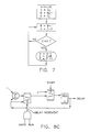
- the geometry used herein is shown in FIGS. 6A and 6B for linear/sector and curved linear transducers, respectively. The important reference points are the phase center, focal point and element position. The phase center will always be the origin of the (x,z) Cartesian coordinate system.
- the focal point is r and the element position is p i .
- the beamformer must compensate for channel to channel differences in the propagation time T p of sound traveling between phase center and p i via a reflector at r .
- the relative delay T d is the difference between the propagation time for channel i and the propagation time for the phase center.
- T p and T d are as follows: T d ( x i , ⁇ , r ) ⁇ 1 c (( x 2 i + r 2 -2 x i r sin ⁇ ) 1/2 - r ) T p ( x i , ⁇ , r ) ⁇ 1 c (( x 2 i + r 2 -2 x i r sin ⁇ ) 1/2 + r ) T d ( x i , z i , r ) ⁇ 1 c ([ x 2 i +( r - z i ) 2 ] 1/2 - r ) T p ( x i , z i , r ) ⁇ 1 c ([ x 2 i +( r - z i ) 2 ] 1/2 + r ) T p ( x i , z i , r ) ⁇ 1 c ([ x 2 i +( r
- the ultrasonic imaging system incorporating the invention includes a transducer array 10 comprised of a plurality of separately driven transducer elements 12, each of which produces a burst of ultrasonic energy when energized by a pulsed waveform produced by a transmitter 22.
- the ultrasonic energy reflected back to transducer array 10 from the object under study is converted to an electrical signal by each receiving transducer element 12 and applied separately to a receiver 24 through a set of transmit/receive (T/R) switches 26.
- the T/R switches 26 are typically diodes which protect the receive electronics from the high voltages generated by the transmit electronics.
- the transmit signal causes the diodes to shut off or limit the signal to the receiver.
- Transmitter 22 and receiver 24 are operated under control of a scan controller 28 responsive to commands by a human operator.
- a complete scan is performed by acquiring a series of echoes in which transmitter 22 is gated ON momentarily to energize each transducer element 12, and the subsequent echo signals produced by each transducer element 12 are applied to receiver 24.
- a channel may begin reception while another channel is still transmitting.
- the receiver 24 combines the separate echo signals from each transducer element to produce a single echo signal which is used to produce a line in an image on a display monitor 30.
- Transmitter 22 drives transducer array 10 such that the ultrasonic energy produced is directed, or steered, in a beam.
- transmitter 22 imparts a time delay to the respective pulsed waveforms W. that are applied to successive transducer elements 12 via respective beamformer channels. Each channel has a respective pulser associated therewith.
- the pulse time delays By adjusting the pulse time delays appropriately in a conventional manner, the ultrasonic beam can be directed away from axis 36 by an angle ⁇ and/or focused at a fixed range R.
- a sector scan is performed by progressively changing the time delays in successive excitations. The angle ⁇ is thus changed in increments to steer the transmitted beam in a succession of directions.
- the echo signals produced by each burst of ultrasonic energy reflect from objects located at successive ranges along the ultrasonic beam.
- the echo signals are sensed separately by each transducer element 12 and the magnitude of the echo signal at a particular point in time represents the amount of reflection occurring at a specific range. Due to the differences in the propagation paths between a reflecting point P and each transducer element 12, however, these echo signals will not be detected simultaneously and their amplitudes will not be equal.
- Receiver 24 amplifies the separate echo signals, imparts the proper time delay to each, and sums them to provide a single echo signal which accurately indicates the total ultrasonic energy reflected from point P located at range R along the ultrasonic beam oriented at the angle ⁇ .
- time delays are introduced into each separate beamformer channels of receiver 24.
- the beam time delays for reception are the same delays as the transmission delays described above.
- the time delay of each receiver channel is continuously changing during reception of the echo to provide dynamic focusing of the received beam at the range R from which the echo signal emanates.
- receiver 24 Under the direction of scan controller 28, receiver 24 provides delays during the scan such that steering of receiver 24 tracks the direction ⁇ of the beam steered by transmitter 22 and provides the proper delays and phase shifts to dynamically focus at points P along the beam.
- each transmission of an ultrasonic pulse waveform results in the acquisition of a signal with a magnitude which represents the amount of reflected sound from anatomy located along the ultrasonic beam.
- a detector 25 converts the received signal to display data.
- this would be the envelope of the signal with some additional processing such as edge enhancement and logarithmic compression.
- Scan converter/interpolator 32 receives the display data from detector 25 and converts the data into the desired image for display.
- the scan converter converts the acoustic image data from polar coordinate ( R - ⁇ ) sector format or Cartesian coordinate linear array to appropriately scaled Cartesian coordinate display pixel data at the video rate.
- This scan-converted acoustic data is then output for display on display monitor 30, which images the time-varying amplitude of the envelope of the signal as a grey scale.
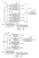
- the receiver comprises a receive beamforming section 34 and a signal processor 38.
- the receive beamforming section 34 of receiver 24 includes separate beamformer channels 35. Each beamformer channel 35 receives the analog echo signal from a respective transducer element.
- the beamformer controller 50 converts scan line and transmit focus numbers to addresses into a channel control memory 54 (see FIG. 4).
- the scan controller 28 (FIG. 1) and beamformer controller 50 (FIG. 2) are loaded by the system host CPU in response to user actions such as changing the display format or connecting a different ultrasound probe.
- each beamformer channel 35 comprises a receive channel and a transmit channel, each channel incorporating delay means 40 and 42 respectively, which are controlled to provide the needed beamforming delays by receive control logic 44 and transmit control logic 46 respectively. Transmit is typically done by using a counter to delay the start of transmit pulse generation. Some systems may also apply relative phase rotations in addition to, or in place of, delays for receive.
- the receive channels also have circuitry 48 for apodizing and filtering the receive pulses.
- the signals entering the summer 36 have been delayed so that when they are summed with delayed signals from each of the other beamformer channels 35, the summed signals indicate the magnitude and phase of the echo signal reflected from anatomy located along the steered beam ( ⁇ ).
- Signal processor 38 receives the beam samples from the summer 36 and produces an output to scan converter 32 (see FIG. 1).
- channel control memory 54 is loaded by the system host CPU 58 and receives addresses corresponding to the scan line or focus number from the beamformer controller 50.
- Channel control of beamforming delays is typically provided by some type of delay generator logic 56 which receives control parameters from control memory 54.
- the control memory must contain all the necessary control parameters associated with that channel for each beam.
- the total amount of memory required for a 128-channel beamformer, to produce 1024 beams is 128 x 1024 x N, where N is the number of control parameters.
- EP-A-0,314,487 describes a delay coefficient calculator for a phase array of ultrasonic transducer elements.
- a beamformer in accordance with claim 1 and an ultrasonic imaging system in accordance with claim 8.
- the present invention is an apparatus for generating the required beamforming delays for an ultrasound imaging system with minimal hardware and software.
- the apparatus performs an algorithm which allows the required computations to be separated into three groups.
- the first group comprises transducer array geometry computations which are beam independent.
- the second group comprises a small number of beam-dependent computations which are channel independent.
- the final group comprises the channel- and beam-dependent calculations which combine the results of the first two groups to generate the required beamforming delays. This last computation is distributed to logic and simple real-time state machines per channel.
- the apparatus of the present invention substitutes simple logic for the large memory required in conventional beamforming delay generation.
- the delay processor in accordance with the basic concept of the invention is shown in FIG. 5.
- the beamforming delay logic 62 combines beam-dependent parameters and channel parameters to produce control parameters needed by the delay generator 64.
- the delay generator 64 generates initial delays and delay increments as a function of the control parameters.
- the beam-dependent parameters are broadcast to all channels simultaneously by the beamformer controller 50 before each beam during scanning.
- the channel parameters are stored in respective registers 60 associated with each channel.
- the channel parameters are loaded into registers 60 by the CPU 58 before scanning. These beam- and channel-dependent parameters are a function of the beamforming geometry.
- T d ( x i , ⁇ , r ) ⁇ x 2 i cos 2 ⁇ 2 c ( r - x i sin ⁇ ) - x i c sin ⁇
- the present invention uses this approximation only to guide its development. Its final accuracy will exceed this approximation.
- the beamforming delay function D ( x i , ⁇ , r ) compensates for the relative propagation delay by subtracting it from a constant T 0 and quantizing by an amount q .
- the desired beamforming delay function is as follows: D ( x i , ⁇ , r ) ⁇ T 0 - T d ( x i , ⁇ , r ) q ⁇ T 0 q + x i qc sin ⁇ - x 2 i cos 2 ⁇ 2 qc ( r - x i sin ⁇ ) If the range r is replaced by the quantized elapsed time from Eq. (2), then the approximation of Eq.
- C n P n m - ⁇ n ( M - P n )
- the internal variable C n can be generated as shown in Eq. (19), given two additional internal variables A n (Eq. (22)) and B n (Eq. (25)). These internal variables must be initialized as shown in Eqs. (23) and (26), and updated as shown in Eqs.
- An important feature of C n is that it decreases monotonically with time ⁇ n given no change in output delay (see Eq. (19)). This is a result of the internal variable A n in Eq. (22) always being positive. Conversely, it will always increase with an increase in the output delay. Thus, the state machine can provide a good approximation by incrementing P n whenever C n crosses 0, i.e. becomes negative.
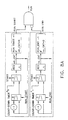
- FIGS. 8A-8C One possible implementation of the delay generator 64 (see FIG. 5) is shown in FIGS. 8A-8C. All registers are initialized with an active low "Start" pulse.
- FIG. 8A depicts two count-down timers to control when the state machine starts and stops running.
- FIG. 8B depicts a state machine core, which updates A n , B n and C n .
- the state machine can produce more accurate results and compensate for initial delay ( J ) errors. Better accuracy is achieved by scaling up all the internal variables, and offsetting their initial values to remove biases. Initial delay errors can be accounted for by adjusting C 0 .
- T d ( x i , ⁇ ,n ) J + M ⁇ n ⁇ n + m ⁇ D ( x i , ⁇ ,n )
- T d ( x i , ⁇ ,n ) J + M ⁇ n ⁇ n + m ⁇ D ( x i , ⁇ ,n )
- the first group contains array geometry, channel-dependent, beam-independent computations performed by the system CPU before scanning. The results of these computations are loaded into registers 60 associated with each channel.
- the second group contains beam-dependent computations which are channel independent.
- the results of these beam-dependent computations are broadcast to all channels during scanning by the beamformer controller 50. They can be computed by the CPU before scanning and then stored in a relatively small "beam" memory which is read during scanning. Alternatively, they can be produced real-time during scanning.
- the last group of computations are extremely simple beam- and channel-dependent calculations using the results of the first two groups of computations. They are distributed, i.e., very simple logic 62 (see FIG. 5) associated with each channel performs the computations in parallel during the previous beam or during dead time between beams. This is a significant reduction in computation and hardware from conventional designs which require complex computations performed per channel and beam. Generally these "prior art" systems need to perform all of these computations prior to scanning, in the system CPU or design workstation, and store them in large memories.
- the channel-dependent variable can be stored per channel before scanning or broadcast during scanning.
- Ten beam-dependent values are broadcast to all channels during scanning: T 0 / q, n x , ⁇ p , x v , D ⁇ p + , D ⁇ p- , m ⁇ + , m ⁇ - , M ⁇ + , and M ⁇ - .
- T 0 is the delay offset to ensure positive delays; the proportionality constant ⁇ p is calculated so that r p is always less than the turn-on range (as the focal range increases, channels are turned on to grow the active aperture as a function of range); x v is the beam phase center position relative to the array face center; and n x , D ⁇ p + , D ⁇ p - , m ⁇ + , m ⁇ - , M ⁇ + , and M ⁇ - are determined in accordance with Eqs.
- each channel For each scan line, each channel must initialize and run the delay state machine(s) using the stored channel-dependent values and broadcast beam-dependent values.
- D ⁇ p sign( x i ) - z i q + T 0 q m
- m ⁇ sign( x i ) M
- M ⁇ sign( x i ) n 0 (
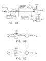
- FIGS. 9A-9E An example of the simple logic required is shown in FIGS. 9A-9E. These computations can be done during the scan line preceding the one for which the computation results are needed, making the computational speed requirement very slow.
- Dedicated logic may be used as shown, or logic may be reduced by multiplexing multipliers between computations or using a very simple microprocessor. All of this logic may be highly integrated on custom integrated circuits together with FIFOs or Cordic rotators that apply the required delay or phase rotations to the transmit and receive signals.
- Separate transmit and receive state machines may be provided per channel.
- the receive state machine is producing delays for the n-th beam
- the transmit state machine is producing delays for the ( n +1)-th beam.
- the channel logic computes the ( n +1)-th scan line receive initialization together with the ( n +2)-th transmit initialization.
- the parallel distributed control architecture of the invention could be applied to any method of beamforming, including, but not limited to, analog beamformers with tap delay lines and/or phase rotations using intermediate frequency mixers or baseband demodulators (phase rotation is often used as an approximation to time delay for relatively narrow bandwidth signals), digital beamformers using FIFOs and/or cordic rotators, demodulators or intermediate frequency mixers, for phase rotation.
- delay includes time delay, tap delay or phase rotation.
- some beamformer architectures may use only the initial delay and delay increments without needing to explicitly accumulate the delay.
- a FIFO can be set to an initial length, and then lengthened by one with each delay increment by holding the read address for one clock cycle while still incrementing the write address.
Claims (10)
- Dispositif de formation de faisceau comprenant une multitude de canaux (35) de dispositif de formation de faisceau et une source (50) de paramètres dépendant du faisceau reliée à chacun desdits canaux de dispositif de formation de faisceau, chacun desdits canaux de dispositif de formation de faisceau comprenant un dispositif de retard (40 ou 42) de signaux et un processeur de retard (62, 64) de formation de faisceau et lesdits processeurs de retard de formation de faisceau fonctionnant en parallèle, caractérisé en ce que chaque canal de dispositif de formation de faisceau comporte un dispositif de mémoire (60), qui, en utilisation, mémorise un paramètre dépendant du canal, et en ce que le processeur de retard de dispositif de formation de faisceau commande la quantité de retard produite par ledit dispositif de retard de signaux en fonction dudit paramètre dépendant du canal mémorisé dans ledit dispositif de mémoire et desdits paramètres dépendant du faisceau.
- Dispositif de formation de faisceau selon la revendication 1, caractérisé en ce que ledit dispositif de formation de faisceau comprend en outre un additionneur (36), et lesdits canaux de dispositif de formation de faisceau sont des canaux de réception reliés audit additionneur.
- Dispositif de formation de faisceau selon la revendication 1, caractérisé en ce que chacun desdits canaux de dispositif de formation de faisceau est un canal d'émission respectif ayant un générateur d'impulsions qui lui est associé (46).
- Dispositif de formation de faisceau selon la revendication 1, caractérisé en ce que chacun desdits processeurs de retard de formation de faisceau comprend :des circuits logiques (62) pour calculer des valeurs d'initialisation et un retard initial à partir dudit paramètre dépendant du canal provenant de ladite mémoire et à partir desdits paramètres dépendant du faisceau ; etdes circuits de générateur (64) de retard pour délivrer des signaux audit dispositif de retard qui provoquent un incrément de retard en réponse à la réception desdites valeurs d'initialisation et dudit retard initial provenant desdits circuits logiques.
- Dispositif de formation de faisce au selon la revendication 1, caractérisé en ce que ladite source de paramètres dépendant du faisceau comprend une unité centrale qui calcule et diffuse lesdits paramètres dépendant du faisceau auxdits canaux de dispositif de formation de faisceau.
- Dispositif de formation de faisceau selon la revendication 1, caractérisé en ce que ladite source de paramètres dépendant du faisceau comprend une mémoire de laquelle sont extraits lesdits paramètres dépendant du faisceau puis diffusés auxdits canaux de dispositif de formation de faisceau.
- Dispositif de formation de faisceau selon la revendication 1, caractérisé en ce que lesdits circuits de générateur de retard comprennent des circuits d'automate fini pour appliquer des règles d'automate fini basées sur lesdites valeurs d'initialisation pour délivrer des signaux d'incrément de retard.
- Système d'imagerie par ultrasons comprenant un réseau de transducteurs (10), un dispositif de formation de faisceau relié audit réseau de transducteurs (34, 36), un processeur de signaux (38) relié audit dispositif de formation de faisceau, un convertisseur à balayage (32) relié audit processeur de signaux, un moniteur d'affichage (30) relié audit convertisseur à balayage, et une source (50) de paramètres dépendant du faisceau reliée audit dispositif de formation de faisceau, ledit réseau de transducteurs comprenant une multitude d'éléments transducteurs (12) et ledit dispositif de formation de faisceau comprenant une multitude de canaux (35) de dispositif de formation de faisceau et des circuits de commutation (26) pour coupler sélectivement lesdits canaux de dispositif de formation de faisceau auxdits éléments transducteurs, chacun desdits canaux de dispositif de formation de faisceau comprenant un dispositif de retard (40 ou 42) de signaux et un processeur de retard (62, 64) de formation de faisceau et lesdits processeurs de retard de formation de faisceau fonctionnant en parallèle, caractérisé en ce que chaque canal de dispositif de formation de faisceau comporte un dispositif de mémoire (60) pour mémoriser un paramètre dépendant du canal, et en ce que le processeur de retard de dispositif de formation de faisceau commande la quantité de retard produite par ledit dispositif de retard de signaux en fonction dudit paramètre dépendant du canal et desdits paramètres dépendant du faisceau.
- Système d'imagerie par ultrasons selon la revendication 8, caractérisé en ce que chacun desdits processeurs de retard de formation de faisceau comprend :des circuits logiques (62) pour calculer des valeurs d'initialisation et un retard initial à partir dudit paramètre dépendant du canal provenant de ladite mémoire et à partir desdits paramètres dépendant du faisceau ; etdes circuits de générateur (64) de retard pour délivrer des signaux audit dispositif de retard qui provoquent un incrément de retard en réponse à la réception desdites valeurs d'initialisation et dudit retard initial provenant desdits circuits logiques.
- Système d'imagerie par ultrasons selon la revendication 9, caractérisé en ce que ladite source de paramètres dépendant du faisceau comprend une unité centrale qui calcule et diffuse lesdits paramètres dépendant du faisceau auxdits canaux de dispositif de formation de faisceau.
Applications Claiming Priority (2)
| Application Number | Priority Date | Filing Date | Title |
|---|---|---|---|
| US581667 | 1995-12-29 | ||
| US08/581,667 US5653236A (en) | 1995-12-29 | 1995-12-29 | Apparatus for real-time distributed computation of beamforming delays in ultrasound imaging system |
Publications (3)
| Publication Number | Publication Date |
|---|---|
| EP0782126A2 EP0782126A2 (fr) | 1997-07-02 |
| EP0782126A3 EP0782126A3 (fr) | 1999-04-07 |
| EP0782126B1 true EP0782126B1 (fr) | 2003-06-25 |
Family
ID=24326092
Family Applications (1)
| Application Number | Title | Priority Date | Filing Date |
|---|---|---|---|
| EP96309272A Expired - Lifetime EP0782126B1 (fr) | 1995-12-29 | 1996-12-19 | Dispositif pour calcul distribué en temps réel des délais pour former le faisceau dans un système d'imagerie ultrasonore |
Country Status (4)
| Country | Link |
|---|---|
| US (1) | US5653236A (fr) |
| EP (1) | EP0782126B1 (fr) |
| JP (1) | JP3700990B2 (fr) |
| DE (1) | DE69628810T2 (fr) |
Cited By (1)
| Publication number | Priority date | Publication date | Assignee | Title |
|---|---|---|---|---|
| US11324481B2 (en) | 2014-12-01 | 2022-05-10 | Clarius Mobile Health Corp. | Ultrasound machine having scalable receive beamformer architecture comprising multiple beamformers with common coefficient generator and related methods |
Families Citing this family (26)
| Publication number | Priority date | Publication date | Assignee | Title |
|---|---|---|---|---|
| US5844139A (en) * | 1996-12-30 | 1998-12-01 | General Electric Company | Method and apparatus for providing dynamically variable time delays for ultrasound beamformer |
| KR100252727B1 (ko) * | 1997-02-04 | 2000-04-15 | 이민화 | 실시간디지털집속을위한집속지연계산방법및그장치 |
| US6123671A (en) * | 1998-12-31 | 2000-09-26 | General Electric Company | Method and apparatus for distributed, agile calculation of beamforming time delays and apodization values |
| US6468213B1 (en) | 1999-09-14 | 2002-10-22 | Ecton, Inc. | Medical diagnostic ultrasound system and method |
| US6508763B1 (en) * | 1999-09-14 | 2003-01-21 | Ecton, Inc. | Medical diagnostic ultrasound system and method |
| US6497664B1 (en) | 1999-09-14 | 2002-12-24 | Ecton, Inc. | Medical diagnostic ultrasound system and method |
| US6524244B1 (en) | 1999-09-14 | 2003-02-25 | Ecton Inc. | Medical diagnostic ultrasound system and method |
| US7678048B1 (en) | 1999-09-14 | 2010-03-16 | Siemens Medical Solutions Usa, Inc. | Medical diagnostic ultrasound system and method |
| US6488625B1 (en) | 1999-09-14 | 2002-12-03 | Ecton, Inc. | Medical diagnostic ultrasound system and method |
| US6592524B2 (en) * | 2000-12-22 | 2003-07-15 | Siemens Medical Solutions Usa, Inc. | Transmit beamformer delay architecture and method for diagnostic medical ultrasound |
| US6638226B2 (en) | 2001-09-28 | 2003-10-28 | Teratech Corporation | Ultrasound imaging system |
| EP1738407B1 (fr) | 2004-04-20 | 2014-03-26 | Visualsonics Inc. | Transducteur ultrasonique en reseau |
| EP1952175B1 (fr) * | 2005-11-02 | 2013-01-09 | Visualsonics, Inc. | Formateur de faisceaux digital pour un système ultrasonore à réseau de transducteurs |
| US20070239013A1 (en) * | 2006-03-22 | 2007-10-11 | Aloka Co., Ltd. | Delay controller for ultrasound receive beamformer |
| US7804736B2 (en) * | 2006-03-30 | 2010-09-28 | Aloka Co., Ltd. | Delay controller for ultrasound receive beamformer |
| CN101190134B (zh) * | 2006-11-28 | 2011-09-07 | 深圳迈瑞生物医疗电子股份有限公司 | 超声波诊断系统中的多波束发射和接收方法及其装置 |
| US9314223B2 (en) * | 2007-10-23 | 2016-04-19 | Shenzhen Mindray Bio-Medical Electronics Co., Ltd. | Multi-stage digital ultrasound beamformer |
| EP3309823B1 (fr) | 2008-09-18 | 2020-02-12 | FUJIFILM SonoSite, Inc. | Transducteurs à ultrasons |
| US9173047B2 (en) | 2008-09-18 | 2015-10-27 | Fujifilm Sonosite, Inc. | Methods for manufacturing ultrasound transducers and other components |
| US9184369B2 (en) | 2008-09-18 | 2015-11-10 | Fujifilm Sonosite, Inc. | Methods for manufacturing ultrasound transducers and other components |
| JP6188393B2 (ja) * | 2012-11-30 | 2017-08-30 | 東芝メディカルシステムズ株式会社 | 超音波診断装置及び制御プログラム |
| US9251781B1 (en) | 2015-04-06 | 2016-02-02 | King Saud University | Pulser logic method and system for an ultrasound beamformer |
| CN105832366B (zh) * | 2016-03-18 | 2019-11-15 | 深圳安盛生物医疗技术有限公司 | 一种用于波束合成过程中的延时实时计算方法 |
| JP7063006B2 (ja) * | 2018-02-27 | 2022-05-09 | セイコーエプソン株式会社 | 超音波センサー、電子機器、及び超音波センサーの駆動方法 |
| CN110840483B (zh) * | 2019-11-15 | 2022-03-18 | 徐州市凯信电子设备有限公司 | 一种用于数字超声诊断仪的实时对数压缩方法、系统 |
| CN113406650A (zh) * | 2021-08-20 | 2021-09-17 | 宁波博海深衡科技有限公司武汉分公司 | 三维侧扫声呐成阵列方法及设备 |
Family Cites Families (5)
| Publication number | Priority date | Publication date | Assignee | Title |
|---|---|---|---|---|
| DE3884905T2 (de) * | 1987-10-29 | 1994-05-05 | Hewlett Packard Co | Verzögerungskoeffizientrechner. |
| US5501219A (en) * | 1993-09-30 | 1996-03-26 | Siemens Medical Systems, Inc. | Real-time dynamic time-of-flight calculator |
| US5581517A (en) * | 1994-08-05 | 1996-12-03 | Acuson Corporation | Method and apparatus for focus control of transmit and receive beamformer systems |
| US5477859A (en) * | 1995-02-13 | 1995-12-26 | General Electric Company | Ultrasound imaging system having spatial filtering preprocessor |
| US5476098A (en) * | 1995-02-13 | 1995-12-19 | General Electric Company | Partially coherent imaging for large-aperture phased arrays |
-
1995
- 1995-12-29 US US08/581,667 patent/US5653236A/en not_active Expired - Lifetime
-
1996
- 1996-12-19 DE DE69628810T patent/DE69628810T2/de not_active Expired - Lifetime
- 1996-12-19 EP EP96309272A patent/EP0782126B1/fr not_active Expired - Lifetime
-
1997
- 1997-01-06 JP JP00020297A patent/JP3700990B2/ja not_active Expired - Lifetime
Cited By (1)
| Publication number | Priority date | Publication date | Assignee | Title |
|---|---|---|---|---|
| US11324481B2 (en) | 2014-12-01 | 2022-05-10 | Clarius Mobile Health Corp. | Ultrasound machine having scalable receive beamformer architecture comprising multiple beamformers with common coefficient generator and related methods |
Also Published As
| Publication number | Publication date |
|---|---|
| EP0782126A2 (fr) | 1997-07-02 |
| US5653236A (en) | 1997-08-05 |
| DE69628810D1 (de) | 2003-07-31 |
| JP3700990B2 (ja) | 2005-09-28 |
| DE69628810T2 (de) | 2004-05-13 |
| EP0782126A3 (fr) | 1999-04-07 |
| JPH09318733A (ja) | 1997-12-12 |
Similar Documents
| Publication | Publication Date | Title |
|---|---|---|
| EP0782126B1 (fr) | Dispositif pour calcul distribué en temps réel des délais pour former le faisceau dans un système d'imagerie ultrasonore | |
| US5487306A (en) | Phase aberration correction in phased-array imaging systems | |
| US6282963B1 (en) | Numerical optimization of ultrasound beam path | |
| EP1004894B1 (fr) | Méthode et appareil d'acquisition de données d'imagerie ultrasonore à haute résolution et à fréquences de trames élevées | |
| US5235986A (en) | Variable origin-variable angle acoustic scanning method and apparatus for a curved linear array | |
| US5566675A (en) | Beamformer for phase aberration correction | |
| US5844139A (en) | Method and apparatus for providing dynamically variable time delays for ultrasound beamformer | |
| US5531117A (en) | Closed loop maximum likelihood phase aberration correction in phased-array imaging systems | |
| Thurstone et al. | A new ultrasound imaging technique employing two-dimensional electronic beam steering | |
| US5230340A (en) | Ultrasound imaging system with improved dynamic focusing | |
| US5345939A (en) | Ultrasound imaging system with dynamic window function | |
| US4989143A (en) | Adaptive coherent energy beam formation using iterative phase conjugation | |
| EP0473959B1 (fr) | Méthode de transformation d'un image sonar à faisceaux multiples | |
| EP1060470B1 (fr) | Procede et dispositif de calcul agile reparti pour des retards dans la formation de rayons et valeurs d'apodisation | |
| EP0916966B1 (fr) | Procédé de focalisation d'un signal ultrasonsore et appareil pour système d'imagerie par ultrasons | |
| US5398216A (en) | Method for detecting two-dimensional flow for ultrasound color flow imaging | |
| US5415173A (en) | Ultrasound diagnosis system | |
| US5817023A (en) | Ultrasound imaging system with dynamic window function generator | |
| US6193665B1 (en) | Doppler angle unfolding in ultrasound color flow and Doppler | |
| EP0120073A1 (fr) | Systeme de mise en image ultrasonique avec correction de l'heterogeneite de la vitesse et de l'interference multivoies, utilisant un reseau de mise en image ultrasonique | |
| GB2041525A (en) | Ultrasonic imaging system utilizing dynamic and pseudo-dynamic focusing | |
| JPH0870404A (ja) | 超音波ビーム形成装置における遅延生成装置 | |
| US5197037A (en) | Method and apparatus for the simultaneous performance of the beam formation and scan conversion in a phased array system | |
| US6443897B1 (en) | Refraction delay error correction using agile beamformer | |
| US6517489B1 (en) | Method and apparatus for forming medical ultrasound images |
Legal Events
| Date | Code | Title | Description |
|---|---|---|---|
| PUAI | Public reference made under article 153(3) epc to a published international application that has entered the european phase |
Free format text: ORIGINAL CODE: 0009012 |
|
| AK | Designated contracting states |
Kind code of ref document: A2 Designated state(s): DE FR IT |
|
| PUAL | Search report despatched |
Free format text: ORIGINAL CODE: 0009013 |
|
| AK | Designated contracting states |
Kind code of ref document: A3 Designated state(s): DE FR IT |
|
| 17P | Request for examination filed |
Effective date: 19991007 |
|
| 17Q | First examination report despatched |
Effective date: 20000615 |
|
| GRAH | Despatch of communication of intention to grant a patent |
Free format text: ORIGINAL CODE: EPIDOS IGRA |
|
| GRAH | Despatch of communication of intention to grant a patent |
Free format text: ORIGINAL CODE: EPIDOS IGRA |
|
| GRAA | (expected) grant |
Free format text: ORIGINAL CODE: 0009210 |
|
| AK | Designated contracting states |
Designated state(s): DE FR IT |
|
| REF | Corresponds to: |
Ref document number: 69628810 Country of ref document: DE Date of ref document: 20030731 Kind code of ref document: P |
|
| PLBE | No opposition filed within time limit |
Free format text: ORIGINAL CODE: 0009261 |
|
| STAA | Information on the status of an ep patent application or granted ep patent |
Free format text: STATUS: NO OPPOSITION FILED WITHIN TIME LIMIT |
|
| ET | Fr: translation filed | ||
| 26N | No opposition filed |
Effective date: 20040326 |
|
| PGFP | Annual fee paid to national office [announced via postgrant information from national office to epo] |
Ref country code: DE Payment date: 20111229 Year of fee payment: 16 |
|
| REG | Reference to a national code |
Ref country code: DE Ref legal event code: R119 Ref document number: 69628810 Country of ref document: DE Effective date: 20130702 |
|
| PG25 | Lapsed in a contracting state [announced via postgrant information from national office to epo] |
Ref country code: DE Free format text: LAPSE BECAUSE OF NON-PAYMENT OF DUE FEES Effective date: 20130702 |
|
| REG | Reference to a national code |
Ref country code: FR Ref legal event code: PLFP Year of fee payment: 20 |
|
| PGFP | Annual fee paid to national office [announced via postgrant information from national office to epo] |
Ref country code: FR Payment date: 20151217 Year of fee payment: 20 |
|
| PG25 | Lapsed in a contracting state [announced via postgrant information from national office to epo] |
Ref country code: IT Free format text: LAPSE BECAUSE OF NON-PAYMENT OF DUE FEES Effective date: 20151219 |
|
| PG25 | Lapsed in a contracting state [announced via postgrant information from national office to epo] |
Ref country code: IT Free format text: LAPSE BECAUSE OF NON-PAYMENT OF DUE FEES Effective date: 20151219 |
|
| PGFP | Annual fee paid to national office [announced via postgrant information from national office to epo] |
Ref country code: IT Payment date: 20151222 Year of fee payment: 20 |
|
| PGRI | Patent reinstated in contracting state [announced from national office to epo] |
Ref country code: IT Effective date: 20170710 |