EP0781642B1 - Method and an apparatus for manufacturing pipes of plastic, and a plastic pipe - Google Patents
Method and an apparatus for manufacturing pipes of plastic, and a plastic pipe Download PDFInfo
- Publication number
- EP0781642B1 EP0781642B1 EP95120574A EP95120574A EP0781642B1 EP 0781642 B1 EP0781642 B1 EP 0781642B1 EP 95120574 A EP95120574 A EP 95120574A EP 95120574 A EP95120574 A EP 95120574A EP 0781642 B1 EP0781642 B1 EP 0781642B1
- Authority
- EP
- European Patent Office
- Prior art keywords
- mandrel
- wall
- pipe
- core
- plastic
- Prior art date
- Legal status (The legal status is an assumption and is not a legal conclusion. Google has not performed a legal analysis and makes no representation as to the accuracy of the status listed.)
- Expired - Lifetime
Links
- 239000004033 plastic Substances 0.000 title claims abstract description 51
- 238000004519 manufacturing process Methods 0.000 title claims abstract description 14
- 238000000034 method Methods 0.000 title claims abstract description 11
- 239000000463 material Substances 0.000 claims abstract description 40
- 238000005192 partition Methods 0.000 claims abstract description 27
- 239000010410 layer Substances 0.000 claims description 18
- 239000002344 surface layer Substances 0.000 claims description 4
- 230000000694 effects Effects 0.000 claims description 3
- 230000003014 reinforcing effect Effects 0.000 claims description 2
- 230000015572 biosynthetic process Effects 0.000 description 3
- 239000006260 foam Substances 0.000 description 2
- 239000000047 product Substances 0.000 description 2
- 239000000872 buffer Substances 0.000 description 1
- 239000011248 coating agent Substances 0.000 description 1
- 238000000576 coating method Methods 0.000 description 1
- 239000003086 colorant Substances 0.000 description 1
- 239000013078 crystal Substances 0.000 description 1
- 230000003247 decreasing effect Effects 0.000 description 1
- 238000001125 extrusion Methods 0.000 description 1
- 239000000835 fiber Substances 0.000 description 1
- 239000012467 final product Substances 0.000 description 1
- 239000011521 glass Substances 0.000 description 1
- 239000000314 lubricant Substances 0.000 description 1
- 239000002245 particle Substances 0.000 description 1
- 239000002994 raw material Substances 0.000 description 1
- 230000002787 reinforcement Effects 0.000 description 1
- 238000007789 sealing Methods 0.000 description 1
Images

Classifications
-
- B—PERFORMING OPERATIONS; TRANSPORTING
- B29—WORKING OF PLASTICS; WORKING OF SUBSTANCES IN A PLASTIC STATE IN GENERAL
- B29C—SHAPING OR JOINING OF PLASTICS; SHAPING OF MATERIAL IN A PLASTIC STATE, NOT OTHERWISE PROVIDED FOR; AFTER-TREATMENT OF THE SHAPED PRODUCTS, e.g. REPAIRING
- B29C48/00—Extrusion moulding, i.e. expressing the moulding material through a die or nozzle which imparts the desired form; Apparatus therefor
- B29C48/25—Component parts, details or accessories; Auxiliary operations
- B29C48/30—Extrusion nozzles or dies
- B29C48/32—Extrusion nozzles or dies with annular openings, e.g. for forming tubular articles
- B29C48/33—Extrusion nozzles or dies with annular openings, e.g. for forming tubular articles with parts rotatable relative to each other
-
- B—PERFORMING OPERATIONS; TRANSPORTING
- B29—WORKING OF PLASTICS; WORKING OF SUBSTANCES IN A PLASTIC STATE IN GENERAL
- B29C—SHAPING OR JOINING OF PLASTICS; SHAPING OF MATERIAL IN A PLASTIC STATE, NOT OTHERWISE PROVIDED FOR; AFTER-TREATMENT OF THE SHAPED PRODUCTS, e.g. REPAIRING
- B29C48/00—Extrusion moulding, i.e. expressing the moulding material through a die or nozzle which imparts the desired form; Apparatus therefor
- B29C48/03—Extrusion moulding, i.e. expressing the moulding material through a die or nozzle which imparts the desired form; Apparatus therefor characterised by the shape of the extruded material at extrusion
- B29C48/09—Articles with cross-sections having partially or fully enclosed cavities, e.g. pipes or channels
- B29C48/11—Articles with cross-sections having partially or fully enclosed cavities, e.g. pipes or channels comprising two or more partially or fully enclosed cavities, e.g. honeycomb-shaped
-
- B—PERFORMING OPERATIONS; TRANSPORTING
- B29—WORKING OF PLASTICS; WORKING OF SUBSTANCES IN A PLASTIC STATE IN GENERAL
- B29C—SHAPING OR JOINING OF PLASTICS; SHAPING OF MATERIAL IN A PLASTIC STATE, NOT OTHERWISE PROVIDED FOR; AFTER-TREATMENT OF THE SHAPED PRODUCTS, e.g. REPAIRING
- B29C48/00—Extrusion moulding, i.e. expressing the moulding material through a die or nozzle which imparts the desired form; Apparatus therefor
- B29C48/03—Extrusion moulding, i.e. expressing the moulding material through a die or nozzle which imparts the desired form; Apparatus therefor characterised by the shape of the extruded material at extrusion
- B29C48/09—Articles with cross-sections having partially or fully enclosed cavities, e.g. pipes or channels
-
- B—PERFORMING OPERATIONS; TRANSPORTING
- B29—WORKING OF PLASTICS; WORKING OF SUBSTANCES IN A PLASTIC STATE IN GENERAL
- B29C—SHAPING OR JOINING OF PLASTICS; SHAPING OF MATERIAL IN A PLASTIC STATE, NOT OTHERWISE PROVIDED FOR; AFTER-TREATMENT OF THE SHAPED PRODUCTS, e.g. REPAIRING
- B29C48/00—Extrusion moulding, i.e. expressing the moulding material through a die or nozzle which imparts the desired form; Apparatus therefor
- B29C48/03—Extrusion moulding, i.e. expressing the moulding material through a die or nozzle which imparts the desired form; Apparatus therefor characterised by the shape of the extruded material at extrusion
- B29C48/12—Articles with an irregular circumference when viewed in cross-section, e.g. window profiles
-
- B—PERFORMING OPERATIONS; TRANSPORTING
- B29—WORKING OF PLASTICS; WORKING OF SUBSTANCES IN A PLASTIC STATE IN GENERAL
- B29C—SHAPING OR JOINING OF PLASTICS; SHAPING OF MATERIAL IN A PLASTIC STATE, NOT OTHERWISE PROVIDED FOR; AFTER-TREATMENT OF THE SHAPED PRODUCTS, e.g. REPAIRING
- B29C48/00—Extrusion moulding, i.e. expressing the moulding material through a die or nozzle which imparts the desired form; Apparatus therefor
- B29C48/03—Extrusion moulding, i.e. expressing the moulding material through a die or nozzle which imparts the desired form; Apparatus therefor characterised by the shape of the extruded material at extrusion
- B29C48/13—Articles with a cross-section varying in the longitudinal direction, e.g. corrugated pipes
-
- B—PERFORMING OPERATIONS; TRANSPORTING
- B29—WORKING OF PLASTICS; WORKING OF SUBSTANCES IN A PLASTIC STATE IN GENERAL
- B29C—SHAPING OR JOINING OF PLASTICS; SHAPING OF MATERIAL IN A PLASTIC STATE, NOT OTHERWISE PROVIDED FOR; AFTER-TREATMENT OF THE SHAPED PRODUCTS, e.g. REPAIRING
- B29C48/00—Extrusion moulding, i.e. expressing the moulding material through a die or nozzle which imparts the desired form; Apparatus therefor
- B29C48/16—Articles comprising two or more components, e.g. co-extruded layers
- B29C48/18—Articles comprising two or more components, e.g. co-extruded layers the components being layers
- B29C48/19—Articles comprising two or more components, e.g. co-extruded layers the components being layers the layers being joined at their edges
-
- B—PERFORMING OPERATIONS; TRANSPORTING
- B29—WORKING OF PLASTICS; WORKING OF SUBSTANCES IN A PLASTIC STATE IN GENERAL
- B29K—INDEXING SCHEME ASSOCIATED WITH SUBCLASSES B29B, B29C OR B29D, RELATING TO MOULDING MATERIALS OR TO MATERIALS FOR MOULDS, REINFORCEMENTS, FILLERS OR PREFORMED PARTS, e.g. INSERTS
- B29K2105/00—Condition, form or state of moulded material or of the material to be shaped
- B29K2105/06—Condition, form or state of moulded material or of the material to be shaped containing reinforcements, fillers or inserts
- B29K2105/12—Condition, form or state of moulded material or of the material to be shaped containing reinforcements, fillers or inserts of short lengths, e.g. chopped filaments, staple fibres or bristles
-
- B—PERFORMING OPERATIONS; TRANSPORTING
- B29—WORKING OF PLASTICS; WORKING OF SUBSTANCES IN A PLASTIC STATE IN GENERAL
- B29L—INDEXING SCHEME ASSOCIATED WITH SUBCLASS B29C, RELATING TO PARTICULAR ARTICLES
- B29L2023/00—Tubular articles
- B29L2023/22—Tubes or pipes, i.e. rigid
Definitions
- the invention relates to a method for manufacturing plastic pipes comprising a smooth inner and outer surface and at least one cavity having the shape of a helix and being located in the pipe wall, the turns of the cavity being separated by means of a partition which interconnects the outer and inner wall of the pipe wall, whereupon plastic material is fed through an annular space located between a tubular casing and a core contained therein, and the cavity is formed by means of a mandrel that is caused to rotate with respect to the casing and the core.
- the invention further relates to an apparatus for manufacturing pipes of plastic, the apparatus comprising a substantially tubular casing, a core that is situated in the casing, that is substantially parallel with the axis of the casing, and that forms an annular space with the casing, and at least one mandrel that is rotatable with respect to the casing and the core and surrounds the core.
- the invention also relates to a plastic pipe comprising a smooth inner and outer wall, and at least one partition that is situated between the walls, that has the shape of a helix, and that is attached to the outer and inner wall.
- Plastic pipes with homogenous walls are both heavy and expensive, especially when they are large in size. Therefore, pipes with a wall consisting of two surface layers have been developed, openings or a lighter material layer being provided between the two layers.
- This kind of structure provides a pipe that is substantially as rigid as a pipe with a homogenous wall in the direction of both the axis and the radius, but that is considerably lighter.
- the layered structure also means that less material is needed. To counterbalance these advantages, however, the extruders required for manufacturing such pipes have a rather complicated structure.
- US Patent 4,364,882 discloses an extruder by means of which pipes having smooth outer and inner surfaces and a foam layer therebetween can be manufactured. Due to the weight of the foam, in most cases the total amount of the weight saved is no more than 30%.
- Dutch Patent Application 7,500,386 discloses an extrusion technique by means of which smooth pipes with longitudinal apertures in the walls are produced. However, the rigidity of such pipes in the direction of the radius is small. It is also known to manufacture pipes with a corrugated interior or exterior, such as Swedish Patent 7500855-7 discloses, but the use of pipes with a corrugated surface is quite limited. It is naturally possible to form a smooth outer surface in a ribbed pipe of the kind described for example in WO 81/00823, but this requires two separate manufacturing stages, which considerably increases the price of the final product and which may impair the mechanical properties of the pipe.
- Plastic pipes are typically manufactured with extruders into which the plastic material is fed from the side.
- the plastic pipe will thus comprise at least one seam on the opposite side from the inlet. This jointing seam is highly disadvantageous especially when glass reinforcements are added to the plastic material.
- Pipes with a smooth inner and outer surface and with walls comprising cavities of the shape of a helix are at present manufactured in such a way that a hollow profile having a square cross-section is extruded, it is twisted around a mandrel to have the shape of a helix, and its helical turns are welded together.
- This manufacturing method is quite slow, however, and the resultant product has an uneven outer surface.
- the welded joints between the turns weaken the product.
- a welded joint having the shape of a helix essentially complicates the sealing of the pipe, whereupon leaks occur easily for example in the joints.
- This kind of manufacturing method is disclosed for example in GB-1 438 321.
- German Auslegeschrift 1,245,582 discloses an apparatus the function of which is to provide in the pipe wall an aperture having the shape of a helical line.
- the apparatus does not operate in the desired manner. This is due to the fact that since the mandrel having the shape of a helical line is attached to a core, they both rotate in the same direction and at the same speed, whereupon motion also occurs in the direction of the circumference in the mass of plastic, the motion being somewhat slower than the rotating motion of the core. Therefore, there will be no cavity having the shape of a helical line in the pipe wall, but the mandrel tears a duct of an indefinite shape in the wall. Also, since the material in the apparatus is supplied axially into the area of the mandrel, the space between the mandrel and the core will not be filled completely, wherefore the inner surface of the pipe will be uneven.
- US 3,464,450 discloses a tubular body for a plastic pipe comprising an outer and an inner wall, which are concentric and defined by rotation surfaces.
- the tubular body has a ringshaped circular cross sectional area so as to define a gap between the outer and inner wall.
- the gap has at least two ribs like turns around helicoidal axes inside the gap interconnecting inner and outer wall.
- the inner and outer wall are extruded by using one and the same material.
- the purpose of the present invention is to provide a method enabling the manufacture of pipes having smooth inner and outer surfaces, no welded joints, and walls which comprise cavities of the shape of a helix and partitions that are placed in such a way that despite its light weight the pipe is highly rigid in the direction of both the axis and the radius.
- the plastic material is fed into the annular space at the inner end of the mandrel through conical inlet ducts to the interior and exterior of the mandrel, the mandrel that has the shape of a helix being situated in the annular space between the core and the mandrel.
- plastic material is fed along conical feed channels into the interior and exterior of the mandrel at its inner end. Some of the plastic material then flows between the mandrel and the core, and this forms the smooth inner surface of the plastic pipe.
- the twisting of the mandrel with respect to both the casing and the core enables the formation of a cavity having the shape of a helix in the pipe wall.
- a preferred embodiment of the invention is characterized in that the mandrel is stopped at times in order to obtain a cavity that is relatively elongated in the longitudinal direction of the pipe, and that the pipe wall is compressed in the area of this cavity.
- the part of the pipe that is thus compressed can be used for example as a sleeve or in the manufacture of a bent pipe.
- At least two conical stators and between them at least one rotatable rotor form between them inlet ducts along which the plastic material can be fed into the exterior and interior of the mandrel.
- the plastic material is fed, by means of conical stators and a rotary rotor situated between them, into the exterior and interior of the mandrel at its inner end, it is made sure that the subchannels located inside and outside the mandrel are filled with the plastic material.
- the rotation of the mandrel with respect to the core in turn enables the formation of a cavity with the shape of a helix in the pipe wall.
- the distance between two successive turns of the mandrel is greater at the rear end of the mandrel than at the front end.
- the apparatus can be constructed such that near the end of the feed channel the core comprises a hollow which is connected to the front end of the core by means of an incline that presses the material between the turns of the mandrel.
- the hollow of the core that is formed in this manner facilitates the flow of the plastic material to the subchannel between the mandrel and the core.
- Another advantage of the invention is that when the invention is utilized the plastic pipe will comprise no seams, wherefore it is very easy to for example seal the pipes at the joints.
- the pipe of the invention is characterized in that the outer and inner wall are formed of different materials that are joined in the partition.
- the apparatus shown schematically in Figure 1 comprises a frame 1 with an associated tubular casing 2.
- a core 3 which is coaxial with the casing 2, which may be fixed or rotating, and which is substantially cylindrical at least at the outer end, is mounted in bearings in the frame 1.
- the casing 2 is spaced from the core, so that an annular duct is formed between the casing and the core.
- the front end of this duct forms the nozzle of the apparatus wherein the pipe protrudes out of the apparatus, whereas the rear end is connected to inclining inlet ducts 4a and 4b for plastic.
- the conical part of the frame 1 forms an outer stator 8a.
- the interior of the apparatus comprises an inner stator 8b which also has a conical outer edge.
- a rotatable rotor 9 is placed between the stators 8a and 8b. Means for rotating the rotor 9 are not shown in Figure 1.
- the rotor 9 and the outer stator 8a border the outer inlet duct 4a for plastic, and correspondingly the rotor 9 and the inner stator 8b border the inner inlet duct 4b for plastic.
- the rotor 9 and/or the stators 8a and 8b comprise grooves, protrusions or other similar means which cause, during the rotation of the rotor 9, the plastic raw material to advance from the inlet ducts 4a and 4b towards the mandrel 5.
- a mandrel 5 having the shape of a helix is placed in the annular space between the casing and the core.
- the mandrel 5 consists of a pipe having a square cross-section and surrounding the core 3 in such a way that the axis of the helix joins the axis of the core.
- the mandrel is spaced from both the core 3 and the casing 2, and it thus divides the annular space between the casing and the core into two subchannels 6 and 7, whereupon the subchannel 6 is located between the casing and the mandrel, and the subchannel 7 between the mandrel and the core.
- the subchannels are preferably equal in size in the direction of the radius.
- Figure 1 shows that the distance between the turns of the mandrel is greater at the rear end located at the inlet ducts 4a and 4b than at the front end of the mandrel located at the nozzle of the apparatus.
- the relatively great distance between the turns of the mandrel at the rear end of the mandrel facilitates the flow of the mass of plastic to the subchannel 7.
- a hollow 10 is formed in the core 3 at the rear end of the mandrel, compared to the front end of the core, so that there will be an extension at this point in the subchannel 7.
- An incline 11 is formed between the hollow 10 and the front of the core, and together with a corresponding incline 12 in the frame this hollow presses the material to the subchannels 6 and 7, and to the spaces between the mandrel turns.
- the rear end of the mandrel is connected to a gearwheel 13 with a bar 14, and by means of these components the mandrel can be caused to rotate around its own axis and around the axis of the core.
- the gearwheel is connected to an actuator that is not shown in the figures. Bearings and seals 15, preventing the plastic from flowing backwards, are placed between the gearwheel 13, the frame 1 and the core 3.
- the apparatus according to Figure 1 operates in the following manner:
- Plastic supplied under pressure through the ducts 4a and 4b flows into the exterior and interior of the mandrel at its inner end, i.e. to the subchannels 6 and 7, and to the spaces between the turns of the mandrel 5. Due to the pressure in the ducts 4a and 4b and to the rotation of the mandrel 5, the material flows from right to left in Figure 1 and finally issues from the nozzle of the apparatus.
- the smooth inner and outer surfaces of the pipe wall are thus formed in the subchannels 6 and 7, whereas the mandrel 5 forms a cavity having the shape of a helix between these surfaces.
- the aperture that remains between the successive turns of the mandrel forms partitions of the pipe wall having the shape of the helix.
- the flow rate of the material must naturally be adapted according to the pitch and rotational velocity of the mandrel.
- the rotational velocity of the mandrel 5 can be easily adjusted to correspond to the flow rate of the material by means of the gearwheel 13.
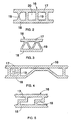
- the right side of Figure 2 shows in longitudinal section a part of the wall of the pipe prepared with the apparatus according to Figure 1.
- the pipe wall 16 thus comprises an outer and inner layer 17 and 18 that are interconnected by means of partitions 19 so that cavities 20 are located between these partitions. Both the partitions 19 and the cavities 20 are thus arranged in the shape of a helix around the axis of the pipe.
- This kind of wall structure provides savings of 30 to 60% in the material compared to a homogenous pipe wall that is equally rigid in the direction of the radius.
- the cavities 20 can be filled completely or in part for example with a foam-like matter.
- An inlet is thus formed for this material at the rear end of the tubular mandrel, and the front end of the mandrel is left open so that the material is fed into the interior of the cavity as it issues from the mandrel.
- a coating such as a plastic layer, decreasing the friction can be formed on the surface of the mandrel.
- apertures through which a lubricant is supplied can be formed in the mandrel.
- Figure 1 shows only one mandrel 5, but it is clear that two or more mandrels can be attached to the gearwheel 13, but in such a case the mandrels have to have a greater pitch, however, than the figure shows.
- the mandrel may naturally be closed instead of tubular.
- FIG. 2 shows an alternative form for the partitions 19, and it can be provided by means of mandrel walls that are bent outwards. Such a form of the partition is advantageous with respect to the strength.
- Figure 3 shows a pipe wall that is provided with an apparatus comprising two mandrels having the cross-sectional shape of an equilateral triangle. These two mandrels are positioned in such a way that they provide the shape shown in Figure 3 wherein partitions 19 alternately incline in different directions with respect to the surface layer of the wall. It is clear that the mandrels may also have a round cross-section.
- Figure 4 shows a pipe wall 16 which is compressed in such a way that the inner and outer layer 17 and 18 are pressed together.
- This kind of structure is achieved in such a way that the rotational motion of the mandrel 5 is interrupted for a while so that no partitions 19 will be formed in that part of the pipe.
- the inner layer 18 of the resultant elongated cavity is subjected to a pressure effect, for example by means of compressed air obtained from the apertures 22 in the core 3 (see Figure 5), at the area of the core situated outside the mandrel.
- the part of the pipe compressed in such a way can be utilized for example as a sleeve or in the formation of a bent pipe.
- Figure 5 shows a pipe wall 16 comprising, between the inner and outer layer 17 and 18, partitions 19 with the shape of an angular Z.
- Partitions 19 having such a shape bend easily, whereupon for example a force acting on the outer layer 17 causes the outer layer 17 to subside and the partitions 19 to yield, but the inner layer 18 remains substantially intact and retains its shape. Therefore, the outer surface 17 of the pipe can be considerably deformed without any effect on the inner surface 18 of the pipe, since the partitions 19 act as kind of buffers between the outer and inner layer 17 and 18, and as a material keeping the layers separate.
- Figure 6 shows an alternative embodiment of the apparatus.
- the mandrel turns located at the inlet end are in this case interconnected by means of material bridges 21 provided in the inner circumference of the mandrel.
- a uniform screw that conically tapers to the outlet end of the apparatus and that continues outside the inclines 11 and 12 as a mandrel having the shape of a helix is thus formed at the inlet end of the apparatus.
- This embodiment enables the manufacture of pipes comprising walls with the inner and outer layer being of different materials or colours in such a way that one material is fed along the outer inlet duct 4a into the exterior of the mandrel at its inner end, i.e. into the subchannel 6, and another material is correspondingly fed along the inner inlet duct 4b into the interior of the mandrel at its inner end, i.e. into the subchannel 7.
- the different materials are thus joined at the partitions 19.
- Figure 6 further shows that the mandrel 5 is attached to the rotor 9, whereupon during the rotation of the rotor 9 the mandrel 5 simultaneously rotates at the same speed to the same direction, i.e. the mandrel 5 does not therefore need a rotation mechanism of its own. The flow rate of the material must naturally be carefully adapted then.
- Figure 6 also shows how apertures 22 are formed at the free end of the core 3, and the apertures can be connected to a source of negative pressure in order to calibrate the pipe walls, or to a source of compressed air in order to compress the pipe wall.
- the plastic pipe can be calibrated in the aforementioned manner from the inside and, if desired, simultaneously also from the outside by means of a cylinder tube calibrator 23.
- the cylinder tube calibrator 23 comprises openings 24 in order to provide a vacuum.
- the core 3 and/or the casing 2 can also be made rotatable. It is clear that the plastic material, as well as the fibre particles or crystals contained therein, can also be oriented inside the pipe wall by means of the rotational movement of the mandrel. Further, double-wall pipes with no partitions can be manufactured when the mandrel 5 is not rotated.
- the core can be prepared of a pipe that is inserted into the apparatus and through it, and that can be coated by means of the apparatus with an insulating surface layer comprising a cavity having the shape of a helix.
- the mandrel can also be mounted in bearings to rotate freely in such a way that the pressure of the mass makes it rotate.
- Reinforcing fibres that can be oriented in the direction of the helix can also be fed into the outer layer 17 and the inner layer 18, or into one of the layers.
- the structural properties of the plastic pipe can thus be considerably improved.
Landscapes
- Engineering & Computer Science (AREA)
- Mechanical Engineering (AREA)
- Manufacturing & Machinery (AREA)
- Extrusion Moulding Of Plastics Or The Like (AREA)
- Shaping Of Tube Ends By Bending Or Straightening (AREA)
- Moulding By Coating Moulds (AREA)
- Rigid Pipes And Flexible Pipes (AREA)
Abstract
Description
Claims (17)
- A method for manufacturing plastic pipes comprising a smooth inner and outer surface and at least one cavity (20) having the shape of a helix and being located in the pipe wall, the turns of the cavity being separated by means of a partition (19) which interconnects the outer and inner wall (17, 18) of the pipe wall, whereupon plastic material is fed through an annular space located between a tubular casing (2) and a core (3) contained therein, the cavity is formed by means of a mandrel (5) that is situated in the annular space, that has the shape of a helix, and that is caused to rotate with respect to the casing (2), the plastic material is fed into the annular space at the inner end of the mandrel (5) through conical inlet ducts (4a, 4b) to the interior and exterior of the mandrel (5), and the mandrel (5) is caused to rotate with respect to the core (3).
- A method according to claim 1, characterized in that the mandrel (5) is stopped at times in order to provide a cavity (20) that is relatively elongated in the longitudinal direction of the pipe, and that the pipe wall (16) is compressed in the area of this cavity.
- A method according to claim 2, characterized in that the pipe wall (16) is compressed by subjecting the inner wall (18) to the effect of compressed air issued from the core (3).
- A method according to claim 1, characterized in that the pipe is coated with an insulating surface layer by pushing the pipe through the apparatus.
- A method according to claim 1, characterized in that the outer and inner surface of the plastic pipe are simultaneously calibrated substantially immediately after the plastic pipe is outside the casing (2).
- An apparatus for manufacturing pipes of plastic, the apparatus comprising a substantially tubular casing (2), a core (3) that is situated in the casing, that is substantially parallel with the axis of the casing, and that forms an annular space with the casing, at least one mandrel (5) that is situated in the annular space at a distance from the casing (2) and the core (3), that is rotatable with respect to the casing (2), that surrounds the core (3) and that has the shape of a helix, at least two conical stators (8a, 8b) and between them at least one rotatable rotor (9), the stators (8a, 8b) and the rotor (9) forming between them inlet ducts (4a, 4b) along which the plastic material can be fed into the exterior and interior of the mandrel (5), the mandrel being rotatable with respect to the core (3).
- An apparatus according to claim 6, characterized in that the distance between two successive turns of the mandrel (5) is greater at the rear end of the mandrel than at the front end.
- An apparatus according to claim 6 or 7, characterized in that the mandrel (5) is mounted in bearings to rotate freely.
- An apparatus according to claim 6 or 7, characterized in that the mandrel (5) is arranged to rotate closely with the rotor (9).
- An apparatus according to any one of the preceding claims 6 to 9, characterized in that the mandrel turns situated at the inlet end of the apparatus are interconnected by means of material bridges (21) to provide a uniform screw.
- An apparatus according to any one of the preceding claims 6 to 10, characterized in that near the end of the inlet ducts (4a, 4b) the core (3) comprises a hollow (10) which is connected to the front end of the core (3) by means of an incline (11) that presses the material between the turns of the mandrel.
- An apparatus according to any one of the preceding claims 6 to 11, characterized in that the apparatus comprises calibration means, situated substantially immediately after the casing (2); for the simultaneous calibration of both the outer and inner surface of the plastic pipe.
- A plastic pipe comprising a smooth inner and outer wall (17, 18), and at least one partition (19) that is situated between the walls, that has the shape of a helix, and that is attached to the outer and inner wall, characterized in that the outer wall (17) and the inner wall (18) are formed of different materials that are joined in the partition (19).
- A plastic pipe according to claim 13, characterized in that the outer and/or inner wall (17, 18) comprise reinforcing fibres that are oriented parallel with the helix.
- A plastic pipe according to any one of the preceding claims 13 to 14, characterized in that the partition (19) has such a structure that when the outer wall (17) is deformed, the partition (19) yields so that the inner wall (18) is deformed less than the outer wall (17).
- A plastic pipe according to any one of the preceding claims 13 to 15, characterized in that the partition (19) has substantially the cross-sectional shape of an angular Z.
- A plastic pipe according to any one of the preceding claims 13 to 16, characterized in that in some places there are no partitions (19), and that the outer and inner layer (17, 18) of the pipe wall (16) are in contact with each other in such places.
Priority Applications (3)
| Application Number | Priority Date | Filing Date | Title |
|---|---|---|---|
| DE69530494T DE69530494T2 (en) | 1995-12-27 | 1995-12-27 | Method and device for producing plastic pipes, and a plastic pipe |
| EP95120574A EP0781642B1 (en) | 1995-12-27 | 1995-12-27 | Method and an apparatus for manufacturing pipes of plastic, and a plastic pipe |
| AT95120574T ATE238154T1 (en) | 1995-12-27 | 1995-12-27 | METHOD AND APPARATUS FOR PRODUCING PLASTIC PIPES, AND A PLASTIC TUBE |
Applications Claiming Priority (1)
| Application Number | Priority Date | Filing Date | Title |
|---|---|---|---|
| EP95120574A EP0781642B1 (en) | 1995-12-27 | 1995-12-27 | Method and an apparatus for manufacturing pipes of plastic, and a plastic pipe |
Publications (2)
| Publication Number | Publication Date |
|---|---|
| EP0781642A1 EP0781642A1 (en) | 1997-07-02 |
| EP0781642B1 true EP0781642B1 (en) | 2003-04-23 |
Family
ID=8219922
Family Applications (1)
| Application Number | Title | Priority Date | Filing Date |
|---|---|---|---|
| EP95120574A Expired - Lifetime EP0781642B1 (en) | 1995-12-27 | 1995-12-27 | Method and an apparatus for manufacturing pipes of plastic, and a plastic pipe |
Country Status (3)
| Country | Link |
|---|---|
| EP (1) | EP0781642B1 (en) |
| AT (1) | ATE238154T1 (en) |
| DE (1) | DE69530494T2 (en) |
Families Citing this family (3)
| Publication number | Priority date | Publication date | Assignee | Title |
|---|---|---|---|---|
| US6405974B1 (en) | 1998-08-12 | 2002-06-18 | F. John Herrington | Ribbed core dual wall structure |
| CA2455234A1 (en) | 2001-08-03 | 2003-02-20 | Proteus, Inc. | Manufacturing process and apparatus for making a helical rib tube |
| HU226663B1 (en) * | 2003-06-20 | 2009-06-29 | Plast Engineering Kutatas Fejl | Method and extrusion apparatus for producing extruded product especially for plastic foil-tubes |
Family Cites Families (5)
| Publication number | Priority date | Publication date | Assignee | Title |
|---|---|---|---|---|
| DE1735017C3 (en) * | 1966-02-07 | 1979-04-05 | Francesco Dr.-Ing. Mailand Steffenini (Italien) | One-piece winding tube made of plastic, especially for holding yarn windings |
| DE1507952A1 (en) * | 1966-03-26 | 1970-01-08 | Becker & Co Naturinwerk | Skin fiber casing and device for its manufacture |
| JPS57126627A (en) * | 1981-01-30 | 1982-08-06 | Matsushita Electric Works Ltd | Forming method of hose |
| DE3212721A1 (en) * | 1982-04-05 | 1983-10-20 | Dynamit Nobel Ag, 5210 Troisdorf | LAUNCH TUBE FOR MISSILE |
| WO1995001251A1 (en) * | 1993-06-30 | 1995-01-12 | Lupke Manfred Arno Alfred | Method and apparatus for forming a double walled thermoplastic tube with integral bells |
-
1995
- 1995-12-27 EP EP95120574A patent/EP0781642B1/en not_active Expired - Lifetime
- 1995-12-27 AT AT95120574T patent/ATE238154T1/en not_active IP Right Cessation
- 1995-12-27 DE DE69530494T patent/DE69530494T2/en not_active Expired - Fee Related
Also Published As
| Publication number | Publication date |
|---|---|
| DE69530494T2 (en) | 2004-04-08 |
| DE69530494D1 (en) | 2003-05-28 |
| ATE238154T1 (en) | 2003-05-15 |
| EP0781642A1 (en) | 1997-07-02 |
Similar Documents
| Publication | Publication Date | Title |
|---|---|---|
| AU704944B2 (en) | An extrusion apparatus and method, a tubular product, and a pipe | |
| US3933960A (en) | Method of extruding fiber reinforced plural layered plastic tubes | |
| US3520966A (en) | Method for the manufacture of tubes of plastics material | |
| CA2736058A1 (en) | Method and apparatus for extrusion of profiled helical tubes | |
| CN86108276A (en) | Extruding die for plastic pipe with ribbed outer surface | |
| EP0781642A1 (en) | Method and an apparatus for manufacturing pipes of plastic, and a plastic pipe | |
| ITMI961282A1 (en) | PROCESS AND PLANT FOR THE PRODUCTION OF PIPES IN RECYCLED THERMOPLASTIC RESINS | |
| CN115871187B (en) | Production line for circumferentially coating fibers and plastics on composite pipe | |
| CN100398297C (en) | Method and apparatus for manufacturing a reinforced socket on an extruded plastic tube made of thermoplastic material | |
| US5888555A (en) | Extrusion die | |
| CN1078126C (en) | Method and apparatus for prepairing an extrudable product, and an extruded product | |
| JPH02231121A (en) | Manufacture of spiral pipe with rib and device therefor | |
| GB2089717A (en) | An extruder for manufacturing plastic pipes | |
| JP3589487B2 (en) | Viscous material extrusion equipment | |
| JPH0735270A (en) | Method for producing fiber reinforced thermoplastic resin pipe | |
| FI71265C (en) | VERKTYG OCH FOERFARANDE FOER FRAMSTAELLNING AV ROER AV PLAST SAMT PLASTROER | |
| AU660009B2 (en) | Extrusion die | |
| US6585923B1 (en) | Extrusion method and extruder | |
| JP2001050435A (en) | Composite flexible tube and method of manufacturing the same | |
| CN217944242U (en) | Double-layer plastic pipe extrusion device | |
| CN219381543U (en) | Plastic extruder | |
| KR100306896B1 (en) | Double Wall Spiral Tube Forming Machine | |
| CN106042324B (en) | An opposed helical short screw extruder | |
| CN210126270U (en) | Inner pipe forming die of spiral corrugated pipe | |
| KR20050118036A (en) | Cotting pipe |
Legal Events
| Date | Code | Title | Description |
|---|---|---|---|
| PUAI | Public reference made under article 153(3) epc to a published international application that has entered the european phase |
Free format text: ORIGINAL CODE: 0009012 |
|
| AK | Designated contracting states |
Kind code of ref document: A1 Designated state(s): AT CH DE ES FR GB GR IT LI NL SE |
|
| 17P | Request for examination filed |
Effective date: 19971013 |
|
| 17Q | First examination report despatched |
Effective date: 19991116 |
|
| RAP1 | Party data changed (applicant data changed or rights of an application transferred) |
Owner name: UPONOR INNOVATION AB |
|
| GRAG | Despatch of communication of intention to grant |
Free format text: ORIGINAL CODE: EPIDOS AGRA |
|
| GRAG | Despatch of communication of intention to grant |
Free format text: ORIGINAL CODE: EPIDOS AGRA |
|
| GRAG | Despatch of communication of intention to grant |
Free format text: ORIGINAL CODE: EPIDOS AGRA |
|
| GRAG | Despatch of communication of intention to grant |
Free format text: ORIGINAL CODE: EPIDOS AGRA |
|
| GRAH | Despatch of communication of intention to grant a patent |
Free format text: ORIGINAL CODE: EPIDOS IGRA |
|
| GRAH | Despatch of communication of intention to grant a patent |
Free format text: ORIGINAL CODE: EPIDOS IGRA |
|
| GRAA | (expected) grant |
Free format text: ORIGINAL CODE: 0009210 |
|
| AK | Designated contracting states |
Designated state(s): AT CH DE ES FR GB GR IT LI NL SE |
|
| PG25 | Lapsed in a contracting state [announced via postgrant information from national office to epo] |
Ref country code: NL Free format text: LAPSE BECAUSE OF FAILURE TO SUBMIT A TRANSLATION OF THE DESCRIPTION OR TO PAY THE FEE WITHIN THE PRESCRIBED TIME-LIMIT Effective date: 20030423 Ref country code: LI Free format text: LAPSE BECAUSE OF FAILURE TO SUBMIT A TRANSLATION OF THE DESCRIPTION OR TO PAY THE FEE WITHIN THE PRESCRIBED TIME-LIMIT Effective date: 20030423 Ref country code: IT Free format text: LAPSE BECAUSE OF FAILURE TO SUBMIT A TRANSLATION OF THE DESCRIPTION OR TO PAY THE FEE WITHIN THE PRE;WARNING: LAPSES OF ITALIAN PATENTS WITH EFFECTIVE DATE BEFORE 2007 MAY HAVE OCCURRED AT ANY TIME BEFORE 2007. THE CORRECT EFFECTIVE DATE MAY BE DIFFERENT FROM THE ONE RECORDED.SCRIBED TIME-LIMIT Effective date: 20030423 Ref country code: FR Free format text: LAPSE BECAUSE OF NON-PAYMENT OF DUE FEES Effective date: 20030423 Ref country code: CH Free format text: LAPSE BECAUSE OF FAILURE TO SUBMIT A TRANSLATION OF THE DESCRIPTION OR TO PAY THE FEE WITHIN THE PRESCRIBED TIME-LIMIT Effective date: 20030423 Ref country code: AT Free format text: LAPSE BECAUSE OF FAILURE TO SUBMIT A TRANSLATION OF THE DESCRIPTION OR TO PAY THE FEE WITHIN THE PRESCRIBED TIME-LIMIT Effective date: 20030423 |
|
| REG | Reference to a national code |
Ref country code: GB Ref legal event code: FG4D |
|
| REG | Reference to a national code |
Ref country code: CH Ref legal event code: EP |
|
| REF | Corresponds to: |
Ref document number: 69530494 Country of ref document: DE Date of ref document: 20030528 Kind code of ref document: P |
|
| PG25 | Lapsed in a contracting state [announced via postgrant information from national office to epo] |
Ref country code: SE Free format text: LAPSE BECAUSE OF FAILURE TO SUBMIT A TRANSLATION OF THE DESCRIPTION OR TO PAY THE FEE WITHIN THE PRESCRIBED TIME-LIMIT Effective date: 20030723 Ref country code: GR Free format text: LAPSE BECAUSE OF FAILURE TO SUBMIT A TRANSLATION OF THE DESCRIPTION OR TO PAY THE FEE WITHIN THE PRESCRIBED TIME-LIMIT Effective date: 20030723 |
|
| NLV1 | Nl: lapsed or annulled due to failure to fulfill the requirements of art. 29p and 29m of the patents act | ||
| PG25 | Lapsed in a contracting state [announced via postgrant information from national office to epo] |
Ref country code: ES Free format text: LAPSE BECAUSE OF FAILURE TO SUBMIT A TRANSLATION OF THE DESCRIPTION OR TO PAY THE FEE WITHIN THE PRESCRIBED TIME-LIMIT Effective date: 20031030 |
|
| REG | Reference to a national code |
Ref country code: CH Ref legal event code: PL |
|
| PLBE | No opposition filed within time limit |
Free format text: ORIGINAL CODE: 0009261 |
|
| STAA | Information on the status of an ep patent application or granted ep patent |
Free format text: STATUS: NO OPPOSITION FILED WITHIN TIME LIMIT |
|
| 26N | No opposition filed |
Effective date: 20040126 |
|
| EN | Fr: translation not filed | ||
| PGFP | Annual fee paid to national office [announced via postgrant information from national office to epo] |
Ref country code: GB Payment date: 20051114 Year of fee payment: 11 |
|
| PGFP | Annual fee paid to national office [announced via postgrant information from national office to epo] |
Ref country code: DE Payment date: 20051117 Year of fee payment: 11 |
|
| PG25 | Lapsed in a contracting state [announced via postgrant information from national office to epo] |
Ref country code: DE Free format text: LAPSE BECAUSE OF NON-PAYMENT OF DUE FEES Effective date: 20070703 |
|
| GBPC | Gb: european patent ceased through non-payment of renewal fee |
Effective date: 20061227 |
|
| PG25 | Lapsed in a contracting state [announced via postgrant information from national office to epo] |
Ref country code: GB Free format text: LAPSE BECAUSE OF NON-PAYMENT OF DUE FEES Effective date: 20061227 |