CN115871187B - Production line for circumferentially coating fibers and plastics on composite pipe - Google Patents
Production line for circumferentially coating fibers and plastics on composite pipe Download PDFInfo
- Publication number
- CN115871187B CN115871187B CN202310154703.9A CN202310154703A CN115871187B CN 115871187 B CN115871187 B CN 115871187B CN 202310154703 A CN202310154703 A CN 202310154703A CN 115871187 B CN115871187 B CN 115871187B
- Authority
- CN
- China
- Prior art keywords
- plastic
- continuous fiber
- fiber
- mandrel
- section
- Prior art date
- Legal status (The legal status is an assumption and is not a legal conclusion. Google has not performed a legal analysis and makes no representation as to the accuracy of the status listed.)
- Active
Links
- 239000000835 fiber Substances 0.000 title claims abstract description 202
- 239000004033 plastic Substances 0.000 title claims abstract description 106
- 229920003023 plastic Polymers 0.000 title claims abstract description 106
- 239000002131 composite material Substances 0.000 title claims abstract description 69
- 238000004519 manufacturing process Methods 0.000 title claims abstract description 31
- 239000011248 coating agent Substances 0.000 title claims abstract description 11
- 238000000576 coating method Methods 0.000 title claims abstract description 11
- 238000005096 rolling process Methods 0.000 claims abstract description 11
- 239000010410 layer Substances 0.000 claims description 51
- 230000003014 reinforcing effect Effects 0.000 claims description 33
- 238000004804 winding Methods 0.000 claims description 18
- 229920001169 thermoplastic Polymers 0.000 claims description 13
- 239000004416 thermosoftening plastic Substances 0.000 claims description 13
- 239000002985 plastic film Substances 0.000 claims description 12
- 239000000463 material Substances 0.000 claims description 8
- 230000002093 peripheral effect Effects 0.000 claims description 8
- 238000005253 cladding Methods 0.000 claims description 7
- 238000013016 damping Methods 0.000 claims description 5
- 238000003825 pressing Methods 0.000 claims description 5
- 239000011241 protective layer Substances 0.000 claims description 5
- 238000011144 upstream manufacturing Methods 0.000 claims description 3
- 238000001125 extrusion Methods 0.000 claims description 2
- 239000006223 plastic coating Substances 0.000 claims description 2
- 150000001875 compounds Chemical class 0.000 claims 1
- 238000000034 method Methods 0.000 abstract description 17
- 238000007599 discharging Methods 0.000 description 10
- 239000004698 Polyethylene Substances 0.000 description 6
- -1 polyethylene Polymers 0.000 description 6
- 229920000573 polyethylene Polymers 0.000 description 6
- 239000002990 reinforced plastic Substances 0.000 description 4
- 239000003365 glass fiber Substances 0.000 description 2
- 238000012986 modification Methods 0.000 description 2
- 230000004048 modification Effects 0.000 description 2
- VGGSQFUCUMXWEO-UHFFFAOYSA-N Ethene Chemical compound C=C VGGSQFUCUMXWEO-UHFFFAOYSA-N 0.000 description 1
- 239000005977 Ethylene Substances 0.000 description 1
- 229920002430 Fibre-reinforced plastic Polymers 0.000 description 1
- 230000006835 compression Effects 0.000 description 1
- 238000007906 compression Methods 0.000 description 1
- 230000000694 effects Effects 0.000 description 1
- 239000003733 fiber-reinforced composite Substances 0.000 description 1
- 239000011151 fibre-reinforced plastic Substances 0.000 description 1
- 230000002787 reinforcement Effects 0.000 description 1
- 239000002356 single layer Substances 0.000 description 1
- XLYOFNOQVPJJNP-UHFFFAOYSA-N water Substances O XLYOFNOQVPJJNP-UHFFFAOYSA-N 0.000 description 1
Images
Abstract
The invention provides a production line for circumferentially coating fibers and plastics on a composite pipe, which comprises continuous fiber release equipment, a first plastic extruder, core mold driving equipment and a socket section pinch roller assembly, wherein the continuous fiber release equipment is arranged on the first plastic extruder; the mandrel driving equipment is suitable for driving the mandrel to rotate, the mandrel is loaded with the composite pipe which is manufactured by the previous procedure and is coated with the circumferential fiber and the plastic, and the mandrel driving equipment drives the mandrel to rotate by driving the mandrel to rotate, so that the composite pipe on the mandrel is driven to rotate; the continuous fiber release equipment releases continuous fibers, the surface of the continuous fibers is coated with molten plastics by the first plastic extruder, the surface of the continuous fibers is coated with the molten plastics, and the continuous fibers are gradually wound and coated on the outer wall of the bell section of the composite pipe under the rolling action of the bell section pinch roller assembly in the process that the mandrel driving equipment drives the composite pipe to rotate; after the continuous fibers are coated on the outer circumferential surface of the socket section in a multi-layer manner, the radial internal pressure resistance of the socket section and the rigidity of the external pressure resistance ring of the pipe body can be greatly enhanced.
Description
Technical Field
The invention relates to the technical field of fiber reinforced composite pipe production, in particular to a production line for circumferentially coating fibers and plastics on a composite pipe.
Background
The manufacturing of the existing large-caliber thermoplastic glass fiber reinforced polyethylene sheet material winding forming pressure pipe material is generally completed by adopting a sectional manufacturing method, a fixed-length round roller is firstly adopted as a pipe core mold, different layers of plastic and glass fiber reinforced sheet materials are spirally wound on the outer wall of the core mold from inside to outside in a forward and reverse mode, a four-layer structure comprising a cohesive ethylene layer, a middle pipe material fiber reinforced layer, a polyethylene outer protective layer and a ring stiffness corrugated winding layer is gradually formed, all the four-layer structure adopts a layered spiral winding forming process, a small extruder and a narrow single-layer fiber sheet material are adopted to produce the large-caliber pipe material, and the production efficiency is extremely low; in addition, the tubular product fiber reinforcement layer does not have axial parallel fibers, does not have circumferential parallel fibers, and has poor axial, circumferential and ring stiffness properties.
The inventor provides a new production line and a production method for producing a large-caliber thermoplastic fiber net reinforced plastic composite pipe, which can wrap and wind a longitudinal and transverse fiber net sheet outside a core mold in a whole piece, and a pipe fiber net reinforcing layer is provided with axial parallel fibers and circumferential parallel fibers, so that the production efficiency of the composite pipe is improved, and the performances of the composite pipe in three aspects of radial, axial and ring stiffness are greatly improved.
When the equipment and the production method proposed by the inventor are used for producing the composite pipe, after the polyethylene layer and the middle fiber net reinforcing layer are formed, peripheral coating fiber and plastic layers are needed to be carried out outside, for example, peripheral coating continuous fiber is carried out on the outer circumferential surface of the bell mouth section of the composite pipe, working pressure which is equal to or larger than that of the straight section of the composite pipe is established, and the ring rigidity of the bell mouth section bell and spigot connection position is enhanced; or the middle fiber net reinforcing layer of the straight section of the composite pipe is coated with the trapezoid fiber reinforcing rib, so that the internal pressure resistance strength and the ring stiffness of the composite pipe are improved, and the practical and usable large-caliber thermoplastic fiber net reinforced plastic composite pipe can be formed. The inventors have therefore devised a production line for circumferential wrapping of composite tubing with fibres and plastics.
Disclosure of Invention
It is therefore an object of the present invention to provide a production line for circumferential wrapping of composite tubing with fibres and plastics.
To this end, the invention provides a production line for circumferential wrapping of composite tubing with fibers and plastic, comprising: a continuous fiber releasing device for releasing the continuous fiber bundles;
a first plastic extruder disposed downstream of the continuous fiber discharge apparatus for receiving the continuous fiber strands from the continuous fiber discharge apparatus and cladding a surface of the continuous fiber strands with molten plastic;
the mandrel driving device is arranged at the downstream of the first plastic extruder, is suitable for receiving a mandrel carrying the composite pipe to be coated and can drive the mandrel to rotate;
and the socket section pinch roller assembly is arranged on one side of the socket section and used for rolling towards one side of the circumferential outer wall of the socket section.
As a preferred embodiment, the method further comprises: a flattening device disposed between the first plastic extruder and the mandrel drive apparatus; for receiving the continuous fiber bundles coated with molten plastic from the surface of the first plastic extruder and extruding them into fiber-impregnated composite sheets.
Preferably, the continuous fiber releasing device comprises a plurality of continuous fiber rolls, and each continuous fiber roll can release one continuous fiber bundle.
As a preferred embodiment, the method further comprises: the fiber bundle damping unreeler or the constant-tension fiber bundle unreeler is arranged in pairs with each continuous fiber roll and is used for controlling the tension of the continuous fiber bundles caused by traction to be always kept within a set value range.
As a preferred embodiment, the method further comprises: a split flattening machine disposed between the continuous fiber discharging device and the first plastic extruder for flattening the continuous fiber bundles from the continuous fiber discharging device into a plane before entering the first plastic extruder.
As a preferred scheme, the structure of the beam splitting flattening machine comprises:
a first carrier roller for supporting the continuous fiber bundles released from the continuous fiber releasing device;
the beam splitting teeth are arranged at the downstream of the first carrier roller and are used for splitting the continuous fiber bundles conveyed by the first carrier roller into a row of fiber bundles which are uniformly and planarly ordered;
the second carrier roller is arranged at the downstream of the beam splitting teeth;
and the compression roller is arranged in a vertical pairing way with the second carrier roller to form a rolling structure for extrusion conveying.
As a preferred solution, a second plastic extruder is provided upstream or downstream of the flattening device for extruding the composite wound plastic protective layer.
As a preferred embodiment, the method further comprises: and the guide rail device is used for installing the mandrel driving device and enabling the mandrel driving device to move back and forth on the guide rail device along the axial direction of the composite pipe.
As a preferred embodiment, the method further comprises: the trapezoid die is adjustably arranged at the outlet of the plastic coating die of the first plastic extruder and is of an up-down opening-closing or left-right opening-closing structure, and the trapezoid die is used for folding plastic-coated fiber sheets into trapezoid thermoplastic fiber reinforcing ribs when the trapezoid die is folded.
As a preferred embodiment, the method further comprises: the corrugated pipe releasing device is used for releasing the corrugated pipe;
and the third plastic extruder is arranged at the downstream of the corrugated pipe releasing device and is used for receiving the corrugated pipe from the corrugated pipe releasing device and coating molten plastic on the outer surface of the corrugated pipe.
As a preferred embodiment, the method further comprises: and the reinforcing rib pinch roller is arranged on one side of the core die and used for rolling towards one side of the circumferential outer wall of the core die.
The technical scheme provided by the invention has the following advantages:
the invention relates to a production line for circumferentially coating fibers and plastics on a composite pipe, which comprises continuous fiber release equipment, a first plastic extruder, core mold driving equipment and a bellmouth section pinch roller assembly; the mandrel driving equipment is suitable for driving the mandrel to rotate, the mandrel is loaded with the composite pipe to be coated manufactured through the previous procedure, and the mandrel driving equipment drives the mandrel to rotate so as to drive the composite pipe to be coated on the mandrel to rotate; the continuous fiber release equipment releases continuous fiber bundles, the surface of the continuous fiber bundles is coated with molten plastic by the first plastic extruder, the surface of the continuous fiber bundles is coated with the molten plastic, and the continuous fiber bundles are gradually wound and coated on the outer wall of the axial fiber layer of the bell section of the composite pipe in the process that the core mold driving equipment drives the composite pipe to rotate; the bellmouth section pinch roller assembly is arranged on one side of the bellmouth section, can roll towards one side of the peripheral outer wall of the bellmouth section, and rolls the continuous fiber bundles coated with molten plastics and coated on the bellmouth section onto the peripheral outer wall of the bellmouth section; after the circumferential continuous fiber bundles are extruded and coated on the outer circumferential surface (namely the circumferential outer wall) of the socket section, the radial internal pressure resistance and the external pressure resistance rigidity of the socket section can be greatly enhanced. In particular, when only axial fibers are present on the bell mouth section of the composite pipe to be clad, and no circumferential fibers are present, the requirement for water delivery pressure using the fiber-reinforced plastic composite pipe can be met substantially only after circumferential cladding of the thermoplastic continuous fiber bundles on the bell mouth section using the production line of the present invention.
Drawings
In order to more clearly illustrate the technical solutions in the prior art or in the embodiments of the present invention, the following brief description is given of the drawings used in the description of the prior art or the embodiments.
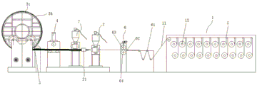
FIG. 1 is a top view of a production line for circumferential cladding of composite tubing in accordance with the present invention.
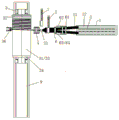
Fig. 2 is a top view of the trapezoidal shaped mold of fig. 1 with the addition of a trapezoid.
Fig. 3 is a side view of fig. 2.
Reference numerals: 1. a continuous fiber releasing device; 11. a continuous fiber bundle; 12. a continuous fiber roll; 2. a first plastic extruder; 21. a trapezoidal mold; 3. a core mold driving device; 31. a composite pipe; 32. a socket section; 33. a straight section; 34. a core mold; 35. a socket section pinch roller assembly; 36. a reinforcing rib pinch roller; 4. a flattening device; 5. a fiber bundle damping unreeler; 6. a beam splitting flattening machine; 61. a first idler; 62. beam splitting teeth; 63. a second idler; 64. a press roller; 7. a second plastic extruder; 81. a bellows release device; 82. a third plastic extruder; 83. a bellows; 9. and a guide rail device.
Detailed Description
In order for those skilled in the art to better understand the present solution, the following description will clearly and fully describe the technical solution in the embodiments of the present application with reference to the accompanying drawings, and it is apparent that the described embodiments are only some embodiments of the present application, not all embodiments. All other embodiments, which can be made by those skilled in the art based on the embodiments herein without making any inventive effort, shall fall within the scope of the present application.
It should be noted that the terms "first," "second," and the like in the claims and description herein are used for distinguishing between similar objects and not necessarily for describing a particular sequential or chronological order. Furthermore, the terms "comprises," "comprising," and "having," and any variations thereof, are intended to cover a non-exclusive inclusion, such that a process, method, system, article, or apparatus that comprises a list of steps or elements is not limited to those steps or elements that are expressly listed or inherent to such process, method, article, or apparatus.
In the present application, the terms "upper", "lower", "left", "right", "front", "rear", "top", "bottom", "inner", "outer", "middle", "vertical", "horizontal", "lateral", "longitudinal" and the like indicate an azimuth or a positional relationship based on that shown in the drawings. These terms are used primarily to better describe the present application and its embodiments and are not intended to limit the indicated device, element or component to a particular orientation or to be constructed and operated in a particular orientation. Also, some of the terms described above may be used to indicate other meanings in addition to orientation or positional relationships, for example, the term "upper" may also be used to indicate some sort of attachment or connection in some cases. The specific meaning of these terms in this application will be understood by those skilled in the art as the case may be. In addition, the term "plurality" shall mean two as well as more than two. It should be noted that, in the case of no conflict, the embodiments and features in the embodiments may be combined with each other.
The present application will be described in detail below with reference to the accompanying drawings in conjunction with embodiments.
Examples
This embodiment provides a production line for circumferential cladding of fibers and plastics on composite tubing, as shown in fig. 1, comprising: a continuous fiber discharge apparatus 1, a first plastic extruder 2, a mandrel drive apparatus 3, and a socket section pinch roller assembly 35.
Wherein the continuous fiber discharging apparatus 1 is for discharging the continuous fiber bundle 11;
a first plastic extruder 2 is arranged downstream of the continuous fiber discharging apparatus 1 for receiving the continuous fiber bundle 11 from the continuous fiber discharging apparatus 1 and cladding the surface of the continuous fiber bundle 11 with molten plastic;
the mandrel driving device 3 is arranged at the downstream of the first plastic extruder 2, is suitable for receiving a mandrel 34 carrying the composite pipe 31 to be coated, and can drive the mandrel 34 to rotate; in operation, a sheet of continuous fiber bundles 11, coated with molten plastic, is wound onto the circumferential outer wall of the socket section 32 of the composite tube 31, with an axial fiber layer;
the socket section pinch roller assembly 35 is installed on one side of the socket section 32 and is used for rolling towards one side of the circumferential outer wall of the socket section 32; when the mandrel driving apparatus 3 drives the mandrel 34 to rotate and winds the continuous fiber bundles 11 coated with the molten plastic around the circumferential outer wall of the socket section 32 of the composite pipe 31, the socket section pinch roller assembly 35 can roll-compound the continuous fiber bundles 11 coated with the molten plastic onto the outer surface of the mandrel 34 to form a regular outer surface.
When the production line of the embodiment is in operation, the mandrel driving device 3 drives the mandrel 34 to rotate, the composite pipe 31 (such as a polyethylene layer and an intermediate fiber net reinforcing layer) is borne on the outer surface of the mandrel 34, and the mandrel 34 rotates to simultaneously drive the composite pipe 31 to synchronously rotate; the continuous fiber bundles 11 released by the continuous fiber releasing device 1 pass through the first plastic extruder 2 to form fiber sheets with the fiber surfaces coated with molten plastic, and the continuous fiber sheets coated with the molten plastic are wound on the outer circumferential surface of the axial fiber layer of the bell mouth section 32 of the composite pipe 31 layer by layer along with the rotation of the composite pipe 31; the bellmouth section pinch roller assembly 35 continuously roll-compounds the continuous fiber sheet coated with molten plastic onto the outer surface of the core mold 34 to form a regular outer circumferential surface.
After the sheet formed of the continuous fiber bundles 11 is wrapped around the outer circumferential surface of the axial fiber layer of the socket section 32, the radial internal pressure resistance and external pressure ring rigidity of the socket section 32 can be greatly enhanced. In particular, when only axial fibers are present on the socket section 32 of the composite tubing 31 to be clad without a circumferential fibrous outer layer, the use requirements of the tubing socket section for internal pressure and ring stiffness can be met basically only after circumferential cladding of the thermoplastic continuous fiber sheet on the socket section 32 using the present production line.
Preferably, the plastic extruder further comprises a flattening device 4 arranged between the first plastic extruder 2 and the mandrel driving device 3; the flattening device 4 is adapted to receive the bundles of continuous fibers 11, the surface of which is covered with molten plastic, from the first plastic extruder 2 and to extrude them into a fiber-impregnated composite sheet. After being coated on the surface of the first plastic extruder 2, the multiple bundles of continuous fiber bundles 11 are rolled into a fiber-impregnated composite sheet by a flattening device 4, so that the continuous fiber sheet can be coated on the bell mouth section 32 of the composite pipe 31 along the circumferential direction more conveniently. In the embodiment, the flattening device 4 is a three-roller rolling flattening machine, and is formed by three pressing rollers, so that the structure is simple. As a variant, the flattening device 4 may also be a conventional two-roll rolling structure.
Preferably, the continuous fiber discharging device 1 comprises a plurality of rolls 12 of continuous fiber, each roll 12 of continuous fiber being capable of discharging a bundle 11 of continuous fiber. After passing through the first plastic extruder 2, the surface of the continuous fiber bundles 11 is uniformly coated with molten plastic, and the continuous fiber releasing device 1 can simultaneously release a plurality of continuous fiber bundles 11, so that the winding efficiency of fibers can be increased.
As a further improvement, the production line of the present embodiment further includes a fiber bundle damping unwinder 5 or a constant tension fiber bundle unwinder, which is provided in pairs with each of the continuous fiber rolls 12 for controlling the tension of the continuous fiber bundles 11 due to being pulled to be always maintained within a set value range.
When the outer wall of the socket section 32 has the structure of flanges and the like, which causes the outer circumferences of the different positions of the socket section 32 to be different, the mandrel 34 drives the composite pipe 31 to rotate once, which causes the lengths of the continuous fiber bundles 11 wound on the different positions of the socket section 32 to be different, if all the continuous fiber bundles 11 are released synchronously, certain continuous fiber bundles 11 are loosened, and then circumferential winding fails; after the fiber bundle damping unreeler 5 is adopted, the release amount of the continuous fiber bundles 11 can be controlled by controlling the tension value of each continuous fiber bundle 11 within a certain range, so that all the continuous fiber bundles 11 can be wound on the outer circumference of the socket section 32 with a certain tension, and the winding effect is uniform.
As a further improvement, the production line of the present embodiment further includes a bundle-splitting flattening machine 6 provided between the continuous fiber discharging apparatus 1 and the first plastic extruder 2 for flattening the continuous fiber bundle 11 from the continuous fiber discharging apparatus 1 into a plane before entering the first plastic extruder 2, thereby facilitating the continuous fiber bundle 11 to be wound on the outer circumferential surface of the socket section 32 with a substantially uniform thickness.
In the present embodiment, the structure of the beam splitting and flattening machine 6 includes: a first carrier roller 61, beam splitting teeth 62, a second carrier roller 63 and a press roller 64; referring to fig. 3, a first carrier roller 61 is provided for supporting the continuous fiber bundle 11 released from the continuous fiber releasing apparatus 1; the beam splitting teeth 62 are disposed downstream of the first carrier roller 61 for splitting the continuous fiber bundle 11 conveyed by the first carrier roller 61 into uniform fiber bundles; a second idler 63 is disposed downstream of the beam splitting teeth 62; the press roller 64 and the second carrier roller 63 are arranged in a vertically paired manner to form a press-conveying rolling structure.
The splitting and flattening machine 6 can divide the continuous fibers from the continuous fiber releasing device 1 into a plurality of fiber bundles, the number of the fibers in each fiber bundle is basically consistent, and when the fibers are divided into uniform fiber bundles and then pass through the first plastic extruder 2, a fiber sheet layer coated with molten plastic with uniform thickness is formed.
As a further development, the production line of the present embodiment further comprises a second plastic extruder 7, arranged upstream or downstream of the flattening device 4, for outputting a molten plastic sheet for winding on the outer circumferential surface of the socket section 32 and/or the straight section 33, forming an outer plastic protective layer.
Also included is a guide rail means 9 for mounting the mandrel drive apparatus 3 and enabling the mandrel drive apparatus 3 to move back and forth on the guide rail means 9 in the axial direction of the composite tubular product 31, thereby enabling the continuous fiber bundles or plastic sheets released by the flattening means 4 to be helically wound on the straight section 33 of the composite tubular product 31.
As a further improvement, as shown in fig. 2-3, the plastic-coated fiber sheet further comprises a trapezoid mold 21 adjustably arranged at the outlet of the coating mold of the first plastic extruder 2, and is in an up-and-down or left-and-right opening-closing structure, and is used for folding the plastic-coated fiber sheet into trapezoid thermoplastic fiber reinforcing ribs when folding.
In general, the trapezoid mold 21 is in a separated state, after the outer circumferential surface of the axial fiber layer of the bell mouth section 32 is wound with the circumferential fiber outer layer, when the outer layer of the pressure-bearing flat section of the composite pipe fiber net (namely, the middle fiber net reinforcing layer) is required to be wound with the reinforcing ribs, the trapezoid mold 21 is adjusted to be in a folded state, at this time, the first plastic extruder 2 deforms the planar continuous fiber sheet into the trapezoid thermoplastic continuous fiber reinforcing ribs through the trapezoid mold, the mandrel driving device 3 drives the mandrel 34 to rotate, the rotating mandrel 34 simultaneously moves along the direction of the guide rail device 9 towards the bell mouth section 32, and the trapezoid thermoplastic continuous fiber reinforcing ribs are spirally wound on the outer wall of the fiber net reinforcing layer at intervals until the spigot mouth section is ended, so as to form the spiral reinforcing rib structure of the pressure-bearing section of the pipe body.
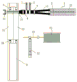
As a variant design, the production line of the present embodiment may further comprise a bellows release device 81 and a third plastic extruder 82, as shown with reference to fig. 1, i.e. a side-by-side version; wherein the bellows release 81 is used to release the bellows 83; a third plastic extruder 82 is provided downstream of the bellows release device 81 for receiving the bellows 83 from the bellows release device 81 and coating the outer surface of the bellows 83 with molten plastic. After the second plastic extruder 7 is used for winding an outer polyethylene layer on the outer layer of the composite pipe 31 (or winding the composite pipe with the fiber net outer layer plastic after the previous procedure), the outer surface of the outer polyethylene layer is coated with a hollow reinforcing rib 83 of molten plastic through a corrugated pipe releasing device 81 and a third plastic extruder 82, so that an outer ring rigidity spiral winding structural layer of the fiber net reinforced plastic composite pipe with the same diameter outer circular surface is formed, and the ring rigidity of the pipe is increased.
Also included is a pinch roller assembly 36, shown in figure 2, mounted on one side of the mandrel 34 for rolling against the circumferential outer wall side of the mandrel 34.
After the continuous composite winding of the peripheral fibers of the bell mouth section 32 and the continuous fiber reinforcing ribs (i.e., trapezoidal thermoplastic continuous fiber reinforcing ribs or corrugated pipes) are continuously wound on the outer wall of the main body part (i.e., the straight section 33) of the composite pipe 31 at intervals, the mandrel 34 returns to the initial position along the guide rail device 9, the second plastic extruder 7 is started, the plastic sheet is extruded, the plastic sheet is continuously wound on the outer layer of the peripheral fibers of the bell mouth section 32 to form a plastic protection layer outside the bell mouth end, after the winding is completed, the mandrel 34 moves along the guide rail device 9 according to a set speed, the plastic sheet is continuously spirally wound along the outer wall of the trapezoidal spiral reinforcing ribs, the outer layer of the fiber spiral reinforcing ribs is continuously rolled by the reinforcing rib pinch rollers 36 until the mandrel 34 is spirally wound on the spigot section of the pipe, the mandrel 34 stops moving axially, the plastic sheet can be continuously wound at zero degrees on the straight part of the spigot section to form the plastic protection layer outside the spigot section, after the thickness is reached, the second plastic extruder 7 is stopped, the plastic sheet is cut and the cut sheet is wound and composited on the spigot straight section.
After the outer layer spiral winding plastic protective layer is completed, the winding manufacturing of the wide fiber web reinforced plastic pipe with the spiral continuous fiber reinforcing ribs is completed.
It is apparent that the above examples are given by way of illustration only and are not limiting of the embodiments. Other variations or modifications of the above teachings will be apparent to those of ordinary skill in the art. It is not necessary here nor is it exhaustive of all embodiments. While still being apparent from variations or modifications that may be made by those skilled in the art are within the scope of the invention.
Claims (4)
1. A production line for circumferentially wrapping a composite pipe with fibers and plastic, comprising:
a continuous fiber releasing device (1) for releasing a continuous fiber bundle (11);
a first plastic extruder (2) arranged downstream of the continuous fiber releasing device (1) for receiving the continuous fiber bundle (11) from the continuous fiber releasing device (1) and cladding a surface of the continuous fiber bundle (11) with molten plastic;
a mandrel driving device (3) which is arranged at the downstream of the first plastic extruder (2), is suitable for receiving a mandrel (34) carrying a composite pipe (31) to be coated, and can drive the mandrel (34) to rotate;
a socket section pinch roller assembly (35) mounted on one side of the socket section (32) for rolling against a circumferential outer wall side of the socket section (32);
further comprises:
-a flattening device (4) arranged between said first plastic extruder (2) and said mandrel drive means (3); for receiving the continuous fiber bundles (11) of which the surface is coated with molten plastic from the first plastic extruder (2) and extruding them into fiber-impregnated composite sheets;
further comprises: a guide rail device (9) for mounting the mandrel driving apparatus (3) and enabling the mandrel driving apparatus (3) to move back and forth on the guide rail device (9) along the axial direction of the composite pipe (31);
further comprises: the trapezoid die (21) is adjustably arranged at the outlet of the plastic coating die of the first plastic extruder (2) and is of an up-and-down opening-closing or left-and-right opening-closing structure, and the trapezoid die is used for folding plastic-coated fiber sheets into trapezoid thermoplastic fiber reinforcing ribs when the trapezoid die is folded;
the continuous fiber releasing device (1) comprises a plurality of continuous fiber rolls (12), wherein each continuous fiber roll (12) can release a bundle of continuous fiber bundles (11);
further comprises:
a fiber bundle damping unreeling device (5) or a constant-tension fiber bundle unreeling device, which is arranged in a pairing way with each continuous fiber roll (12) and is used for controlling the tension of the continuous fiber bundle (11) generated by traction to be always kept within a set value range;
the second plastic extruder (7) is arranged at the upstream or downstream of the flattening device (4) and is used for extruding the composite winding plastic protective layer;
the reinforcing rib pressing wheel (36) is arranged on one side of the core die (34) and used for rolling towards one side of the circumferential outer wall of the core die (34);
when the production line runs, the mandrel driving device (3) drives the mandrel (34) to rotate, the composite pipe (31) is borne on the outer surface of the mandrel (34), and the mandrel (34) rotates to drive the composite pipe (31) to synchronously rotate; after passing through a first plastic extruder (2), the continuous fiber bundles (11) released by the continuous fiber releasing equipment (1) form fiber sheets with the fiber surfaces coated with molten plastic, and the continuous fiber sheets coated with the molten plastic are wound on the outer circumferential surface of an axial fiber layer of a socket section (32) of the composite pipe (31) layer by layer along with the rotation of the composite pipe (31); the bellmouth section pinch roller assembly (35) continuously rolls and compounds the continuous fiber sheet coated with the molten plastic on the outer surface of the core mold (34) to form a regular outer circular surface;
when the outer circumferential surface of the axial fiber layer of the bell-mouth section (32) is wound with the circumferential fiber outer layer, the trapezoid mould (21) is in a separated state, after the outer circumferential surface of the axial fiber layer of the bell-mouth section (32) is wound with the circumferential fiber outer layer, the trapezoid mould (21) is adjusted to be in a closed state when the outer layer of the pressure-bearing straight section of the composite pipe fiber net is required to be wound with the reinforcing rib, at the moment, the first plastic extruder (2) deforms a planar continuous fiber sheet into a trapezoid thermoplastic continuous fiber reinforcing rib through the trapezoid mould, the mandrel driving equipment (3) drives the mandrel (34) to rotate, the rotating mandrel (34) simultaneously moves along the guide rail device (9) towards the bell-mouth section (32), and the trapezoid thermoplastic continuous fiber reinforcing rib is spirally wound on the outer wall of the fiber net reinforcing layer at intervals until the spigot section is finished, so as to form a spiral reinforcing rib structure of the pressure-bearing section of the pipe body;
after the continuous composite winding of the peripheral fiber of the bell mouth section (32) and the continuous spiral winding of the continuous fiber reinforcing rib of the outer wall of the main body part of the composite pipe (31) are completed, the mandrel (34) returns to the initial position along the guide rail device (9), the second plastic extruder (7) is started, the plastic sheet is extruded, the plastic sheet is continuously wound on the outer layer of the peripheral fiber of the bell mouth section (32) to form a plastic protection layer outside the bell mouth end, after the winding is completed, the mandrel (34) moves along the guide rail device (9) according to the set speed, the plastic sheet is continuously spirally wound along the outer wall of the trapezoid spiral reinforcing rib, the outer layer of the fiber spiral reinforcing rib is continuously rolled by the reinforcing rib pressing wheel (36) until the outer layer is spirally wound on the spigot section of the pipe, the mandrel (34) stops moving axially, the plastic sheet can be continuously wound at zero degree at the straight part of the spigot section to form the plastic protection layer outside the spigot section, after the thickness is reached, the second plastic extruder (7) is stopped, the plastic sheet is cut off, and the cut off and the cut sheet is wound and compounded on the spigot section straight section.
2. The production line for circumferential wrapping of composite tubing material with fiber and plastic according to claim 1, further comprising:
a beam splitting flattening machine (6) arranged between the continuous fiber releasing device (1) and the first plastic extruder (2) for flattening the continuous fiber bundles (11) from the continuous fiber releasing device (1) into a plane before entering the first plastic extruder (2).
3. The production line for circumferential wrapping of composite tubes with fibers and plastic according to claim 2, characterized in that the structure of the beam splitting flattening machine (6) comprises:
a first carrier roller (61) for supporting the continuous fiber bundle (11) released from the continuous fiber releasing apparatus (1);
a beam splitting tooth (62) arranged at the downstream of the first carrier roller (61) and used for splitting the continuous fiber bundles (11) conveyed by the first carrier roller (61) into a row of fiber bundles with uniform plane ordering;
a second carrier roller (63) arranged downstream of the beam splitting teeth (62);
and the pressing roller (64) is arranged in an up-down pairing way with the second carrier roller (63) to form a pressing structure for extrusion conveying.
4. The production line for circumferential wrapping of composite tubing material with fiber and plastic according to claim 1, further comprising:
a bellows release device (81) for releasing the bellows (83);
a third plastic extruder (82) disposed downstream of the bellows release device (81) for receiving the bellows (83) from the bellows release device (81) and coating the outer surface of the bellows (83) with molten plastic.
Priority Applications (1)
| Application Number | Priority Date | Filing Date | Title |
|---|---|---|---|
| CN202310154703.9A CN115871187B (en) | 2023-02-23 | 2023-02-23 | Production line for circumferentially coating fibers and plastics on composite pipe |
Applications Claiming Priority (1)
| Application Number | Priority Date | Filing Date | Title |
|---|---|---|---|
| CN202310154703.9A CN115871187B (en) | 2023-02-23 | 2023-02-23 | Production line for circumferentially coating fibers and plastics on composite pipe |
Publications (2)
| Publication Number | Publication Date |
|---|---|
| CN115871187A CN115871187A (en) | 2023-03-31 |
| CN115871187B true CN115871187B (en) | 2023-06-13 |
Family
ID=85761577
Family Applications (1)
| Application Number | Title | Priority Date | Filing Date |
|---|---|---|---|
| CN202310154703.9A Active CN115871187B (en) | 2023-02-23 | 2023-02-23 | Production line for circumferentially coating fibers and plastics on composite pipe |
Country Status (1)
| Country | Link |
|---|---|
| CN (1) | CN115871187B (en) |
Families Citing this family (1)
| Publication number | Priority date | Publication date | Assignee | Title |
|---|---|---|---|---|
| CN116728757B (en) * | 2023-07-17 | 2024-04-16 | 胜利油田北方实业集团有限责任公司 | Preparation tooling for carbon fiber composite tube |
Family Cites Families (8)
| Publication number | Priority date | Publication date | Assignee | Title |
|---|---|---|---|---|
| CN102679047B (en) * | 2012-05-17 | 2014-07-02 | 武汉理工大学 | Continuous filament wound and reinforced thermoplastic pipe and manufacturing process thereof |
| CN102658643A (en) * | 2012-06-01 | 2012-09-12 | 冀州中意复合材料科技有限公司 | Manufacture device of large-diameter glass fiber reinforced plastic flue |
| CN103660308B (en) * | 2012-08-30 | 2018-02-27 | 上海杰事杰新材料(集团)股份有限公司 | Continuous-filament woven fabric enhancing thermoplas tic resin composite and preparation method thereof |
| CN107866954B (en) * | 2016-09-26 | 2020-04-17 | 中国石油化工股份有限公司 | Method and apparatus for manufacturing continuous fiber reinforced thermoplastic resin prepreg tape |
| CN108262987B (en) * | 2016-12-31 | 2024-01-09 | 浙江双林机械股份有限公司 | Winding equipment and winding method for continuous fiber plastic composite pressure pipe |
| CN110481060A (en) * | 2019-08-29 | 2019-11-22 | 江阴市富仁高科股份有限公司 | Oil tank external reinforcing ribs preparation facilities based on prefabricated component |
| CN111745857B (en) * | 2020-07-10 | 2021-03-16 | 江苏奇一科技有限公司 | Preparation method and equipment of unidirectional fiber reinforced resin body with regular cross section |
| CN111775366B (en) * | 2020-07-10 | 2021-04-27 | 江苏奇一科技有限公司 | Preparation method and equipment of unidirectional continuous fiber reinforced thermoplastic composite material |
-
2023
- 2023-02-23 CN CN202310154703.9A patent/CN115871187B/en active Active
Also Published As
| Publication number | Publication date |
|---|---|
| CN115871187A (en) | 2023-03-31 |
Similar Documents
| Publication | Publication Date | Title |
|---|---|---|
| CN1144668C (en) | Method for producing heat-insulation duct | |
| CN115871187B (en) | Production line for circumferentially coating fibers and plastics on composite pipe | |
| US9962750B2 (en) | Systems and methods for forming a pipe carcass using multiple strips of material | |
| CN102269298A (en) | Water pipe, strip, method as well as device for manufacturing water pipe | |
| US4113546A (en) | Apparatus for producing tubes by helically winding sheets | |
| CN202082504U (en) | Fibre reinforced thermoplastic plastic pipe | |
| KR20190031419A (en) | Apparatus And Method for Continuous Manufacturing Fiberglass Reinforced Plastic Pipe | |
| CN102777710B (en) | Multilayer steel compound belt material winding water input pipe, preparation method and device of pipe and steel compound belt material | |
| CN219381584U (en) | Production line for circumferentially coating fibers and plastics on composite pipe | |
| CN100386553C (en) | Stepped combined winding and socket fitting type structure wall pipe and machining method thereof | |
| CN212528600U (en) | Continuous fiber reinforced composite pipe winding equipment | |
| CN1936404A (en) | Continuous-composite-winding socket type structure-wall pipe material and processing method | |
| CN114193730B (en) | Production equipment for reinforced and toughened composite pipe | |
| CN116001251B (en) | Production method and production line of wide fiber net reinforced plastic composite pipe | |
| CN219634590U (en) | Production line of wide fiber web reinforced plastic composite pipe | |
| CN111457166A (en) | Thermoplastic continuous fiber prepreg reinforced thermoplastic composite pipe and manufacturing method thereof | |
| CN102259427A (en) | Rolling forming technology for fiber reinforced thermoplastic pipe | |
| JPS6330265B2 (en) | ||
| CN219171666U (en) | Production line of wide fiber web reinforced plastic composite pipe | |
| CN115972554B (en) | Production line of wide fiber web reinforced plastic composite pipe | |
| CN215750894U (en) | Steel skeleton polyolefin pipeline and production device thereof | |
| CN219236229U (en) | Reinforced composite pipe and manufacturing equipment thereof | |
| CN113007460B (en) | Continuous fiber rope reinforced elliptical stirrup joint ring corrugated pipe | |
| JPH0531782A (en) | Manufacture of fiber reinforced thermoplastic resin composite tube | |
| WO1998003326A1 (en) | Reinforced products and method and apparatus for manufacturing same |
Legal Events
| Date | Code | Title | Description |
|---|---|---|---|
| PB01 | Publication | ||
| PB01 | Publication | ||
| SE01 | Entry into force of request for substantive examination | ||
| SE01 | Entry into force of request for substantive examination | ||
| GR01 | Patent grant | ||
| GR01 | Patent grant | ||
| CB03 | Change of inventor or designer information | ||
| CB03 | Change of inventor or designer information |
Inventor after: Wang Hao Inventor after: Zhao Peixiang Inventor after: Yuan Jianxin Inventor after: Song Jianqiang Inventor before: Zhao Peixiang Inventor before: Wang Hao Inventor before: Yuan Jianxin Inventor before: Song Jianqiang |