EP0781608B1 - Applicator device for application of a coating agent onto a moving base - Google Patents
Applicator device for application of a coating agent onto a moving base Download PDFInfo
- Publication number
- EP0781608B1 EP0781608B1 EP96660089A EP96660089A EP0781608B1 EP 0781608 B1 EP0781608 B1 EP 0781608B1 EP 96660089 A EP96660089 A EP 96660089A EP 96660089 A EP96660089 A EP 96660089A EP 0781608 B1 EP0781608 B1 EP 0781608B1
- Authority
- EP
- European Patent Office
- Prior art keywords
- coating
- applicator
- equivalent
- unit
- agent
- Prior art date
- Legal status (The legal status is an assumption and is not a legal conclusion. Google has not performed a legal analysis and makes no representation as to the accuracy of the status listed.)
- Expired - Lifetime
Links
Images


Classifications
-
- D—TEXTILES; PAPER
- D21—PAPER-MAKING; PRODUCTION OF CELLULOSE
- D21H—PULP COMPOSITIONS; PREPARATION THEREOF NOT COVERED BY SUBCLASSES D21C OR D21D; IMPREGNATING OR COATING OF PAPER; TREATMENT OF FINISHED PAPER NOT COVERED BY CLASS B31 OR SUBCLASS D21G; PAPER NOT OTHERWISE PROVIDED FOR
- D21H23/00—Processes or apparatus for adding material to the pulp or to the paper
- D21H23/02—Processes or apparatus for adding material to the pulp or to the paper characterised by the manner in which substances are added
- D21H23/22—Addition to the formed paper
- D21H23/32—Addition to the formed paper by contacting paper with an excess of material, e.g. from a reservoir or in a manner necessitating removal of applied excess material from the paper
-
- Y—GENERAL TAGGING OF NEW TECHNOLOGICAL DEVELOPMENTS; GENERAL TAGGING OF CROSS-SECTIONAL TECHNOLOGIES SPANNING OVER SEVERAL SECTIONS OF THE IPC; TECHNICAL SUBJECTS COVERED BY FORMER USPC CROSS-REFERENCE ART COLLECTIONS [XRACs] AND DIGESTS
- Y10—TECHNICAL SUBJECTS COVERED BY FORMER USPC
- Y10T—TECHNICAL SUBJECTS COVERED BY FORMER US CLASSIFICATION
- Y10T29/00—Metal working
- Y10T29/49—Method of mechanical manufacture
- Y10T29/49826—Assembling or joining
- Y10T29/4984—Retaining clearance for motion between assembled parts
Definitions
- the invention concerns an applicator device for application of a coating agent onto a moving base, such as a paper or board web, onto the face of a film press roll, or equivalent, which applicator device comprises an applicator beam, which is placed in the direction transverse to the running direction of the moving base to be coated and on whose support the coating-agent feed pipe placed in the cross direction of the machine and/or equivalent coating-agent feed devices as well as a coating head, a nozzle device or equivalent are mounted, said coating head or equivalent being fitted to spread and to smooth the coating agent onto the moving base.
- the object of the present invention is to provide a solution substantially improved, compared with the prior art, for correcting the distortions arising from thermal strains in an applicator device.
- the applicator device in accordance with the present invention is mainly characterized in that the coating-agent feed pipe and/or the equivalent coating-agent feed devices as well as the coating head, coating-agent nozzle device or the equivalent coating-agent spreading and smoothing equipment have been constructed as a single unit, which has been mounted on the applicator beam by means of a joint, which permits relative movements arising from thermal expansion or equivalent between the applicator beam and said unit in the cross direction of the machine while substantially preventing relative movements of the applicator beam and said unit in other directions.
- the coating head or the nozzle equipment has been assembled as a separate and unified "package", which has not been attached to the applicator beam rigidly, but the mode of attaching is such that it permits different thermal elongations of the nozzle equipment and the applicator beam arising from different temperatures, in which case this difference in temperature does not cause any bending or twisting in the nozzle equipment or in the applicator beam.
- the gliding mode of joining in accordance with the invention also permits joining together of different materials without any problems arising in the construction from different thermal expansion coefficients of different materials in respect of the length.
- the construction can be constructed, for example, so that an applicator beam made of acid-proof stainless steel is connected with a nozzle device or equivalent whose material is, for example, plastic, a plastic composite, or equivalent or in whose constructions such materials have been used at least to a considerable extent.
- a nozzle device or equivalent whose material is, for example, plastic, a plastic composite, or equivalent or in whose constructions such materials have been used at least to a considerable extent.
- the forces arising from thermal expansion are problematic with conventional fixed modes of joining even if the different parts of the combination construction were at the same temperature.
- the thermal strains have been eliminated or at least substantially reduced.
- the temperature of the coating agent and, therefore, also of the nozzle equipment can be raised considerably, as a result of which the adjustability and controllability of the coating process can be improved substantially.
- the carrying part of the applicator device i.e. the applicator beam itself
- the carrying part of the applicator device can be kept as cold as possible, for example, by circulating cold water in ducts in the applicator beam, in which case, as a result of condensation, the outer face of the applicator beam can be made to "sweat", which again has the result that the coating agent, such as size or paste, does not adhere to the face of the applicator beam, but the face can be made to remain clean.
- Figure 1 is a fully schematic side view of a size press or of a coating device that uses the film transfer technique, respectively, to which the applicator device in accordance with the invention can be applied.
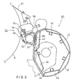
- Figure 2 is a similar schematic side view of a solution in which the coating agent is spread by means of an applicator device in accordance with the invention directly onto the face of a moving paper web.
- Figure 3 is a schematic and partly sectional view of an applicator device in accordance with the invention which can be used in solutions as shown in Figs. 1 and 2.
- Figure 3A is an illustration corresponding to Fig. 3 and showing an alternative embodiment of the applicator device in accordance with the invention.
- the size press or equivalent is denoted generally with the reference numeral 10.
- the size press 10 comprises a frame 11, on which the size press rolls 12,16 have been mounted.
- the bearing housing 13 of the first size press roll 12, i.e. the lower roll, is mounted directly on the frame 11 of the size press and fixed to the frame rigidly.
- the bearing housing 17 of the second size press roll, i.e. the upper roll is mounted on a loading arm 19, which is linked pivotally by means of a pivot shaft 20 transverse to the machine direction on the frame 11 of the size press.
- loading cylinders 22 are provided, by whose means the loading arm 19 is loaded so as to produce a nip pressure of the desired magnitude in the nip N formed by the lower roll 12 and the upper roll 16.
- Either one of the size press rolls 12,16, preferably the upper roll 16, or, as an alternative, both of the size press rolls can be variable-crown rolls in order that the nip N pressure could be brought to the desired level in the cross direction of the machine.
- Each size press roll 12,16 is provided with means of application 15,21, by whose means the size films or equivalent films of coating agent are spread and smoothed onto the faces 14,18 of said rolls.
- the coating-agent films are transferred from the roll 12,16 faces 14,18 to the web W'.
- the applicator devices 15,21 shown in Fig. 1 are applicator devices in accordance with the invention, which will be described in more detail in relation to Fig. 3.
- Fig. 2 shows a solution in which the layer of coating agent is applied directly onto the face of a paper or board web W.
- the equipment comprises a backup roll 30, whose bearing housing 32 is mounted on the frame 33.
- the paper or board web W is passed over a certain distance along the face 31 of the backup roll, in which connection the coating-agent layer is spread by means of the applicator device 35 directly onto the web W.
- the coated web is denoted with the reference denotation W'.
- the embodiment of the applicator device 35 is similar to the applicator devices shown in Fig. 1, and with respect to a more detailed description reference is, also in this connection, made to Fig. 3.
- the applicator device in accordance with the invention is illustrated as quite a schematic solution, and, as is shown in the figure, the applicator device comprises an applicator beam 40, which has been mounted on the frame constructions 43 of the machine pivotally in relation to the articulation shaft 41 placed in the cross direction of the machine. Further, the applicator device includes a coating-agent nozzle device, coating head or equivalent, which is denoted generally with the reference numeral 50, which has been formed as a unified unit in a way in accordance with the invention, and which unit is further, in a way in accordance with the invention, mounted on the applicator beam 40.
- a coating-agent nozzle device, coating head or equivalent which is denoted generally with the reference numeral 50, which has been formed as a unified unit in a way in accordance with the invention, and which unit is further, in a way in accordance with the invention, mounted on the applicator beam 40.
- the unit that forms the nozzle device or the equivalent coating head comprises a frame 51, which includes a feed pipe 52, running in the cross direction of the machine, for the coating agent, such as size, paste or equivalent.
- the unit 50 further comprises a doctor device or an equivalent coating-agent spreading member 54, which is a rod mounted revolving in a cradle, in the exemplifying embodiment shown in the figure.
- the unit 50 comprises a coating-agent chamber 53, into which the coating agent is fed out of the feed pipe 52.
- the front wall that defines the chamber 53 is, in Fig. 3, denoted with the reference numeral 55.
- the unit 50 can include a coating head or an equivalent nozzle device of any suitable type whatsoever, by whose means the coating agent is spread and smoothed onto the moving base B, which is, in Fig. 3, for example, a face of a film press roll or a paper or board web running along the face of a backup roll.
- the edge doctors are denoted with the reference numeral 57, and, as is shown in the figure, in the exemplifying embodiment illustrated the edge doctors 57 are also attached to the unit 50.
- the adjusting spindles are denoted with the reference numeral 56.
- the unit 50 that comprises the coating head or nozzle device is attached to the applicator beam 40 by means of a joint 60 in accordance with the invention.
- the joint 60 shown in Fig. 6 comprises a joint piece attached to the wall of the applicator beam 40, and a corresponding backed-off groove has been formed onto the frame 51 of the unit 50 that comprises the coating head or an equivalent nozzle device. It is an essential feature of the joint 60 shown that it permits free thermal expansion of the unit 50 that comprises the coating head or the equivalent nozzle device, in which case no bending of the applicator beam 40 as a function of temperature takes place.
- the joint 60 is a glide joint, which permits relative movements of the unit 50 and the applicator beam 40 in the cross direction of the machine, but which joint 60 keeps the unit 50 that comprises the coating head or the equivalent nozzle device in the other directions precisely in its position in relation to the applicator beam 40.
- the dovetail joint shown in Fig. 3 is highly suitable for this purpose, even though other joint modes with similar properties can also be used.
- the coating agent can be passed into the feed pipe 52 and from it further onto the base B to be coated at a very high temperature, in which connection the unit 50 that includes the coating head or the equivalent nozzle device can expand freely by the effect of heat in the cross direction of the machine independently from the applicator beam 40.
- the difference in temperature between the unit 50 that includes the coating head or the equivalent nozzle device and the applicator beam 40 can be increased further by cooling the applicator beam 40.
- ducts 42 have been formed into the applicator beam 40 for cooling water.
- the outer face of the applicator beam 40 can be brought to a temperature substantially lower than the temperature in the environment, in which case, as a result of condensation, moisture is gathered on the face of the applicator beam 40, i.e. the applicator beam 40 starts "sweating".
- the joint area 60 can, if necessary, be made of an insulating material.
- Fig. 3A an embodiment of the invention is shown which permits the use of different materials in the applicator beam 40 and in the unit 50 that includes the coating head or the equivalent nozzle device, i.e. combining of materials with different thermal expansion coefficients into combination structures, even better.
- the embodiment of Fig. 3A further reduces the conduction of heat between the applicator beam 40 and the unit 50 that includes the coating head or the equivalent nozzle device.
- Fig. 3A for the parts corresponding to parts in Fig. 3, the same reference denotations have been used, and in the following the embodiment of Fig. 3A will be described in the respects only in which it differs from the embodiment of Fig. 3.
- the joint 60a between the applicator beam 40 and the unit 50 that includes the coating head or the equivalent nozzle device has been formed so that support racks or corresponding support shelves 61a have been fixed to the wall of the applicator beam 40 by means of fastening members 62a.
- the fastening members 62a can consist of screw members or equivalent, but the fastening of the support racks or equivalent support shelves 61a to the wall of the applicator beam 40 can also be carried out, for example, by welding.
- the support shelves 61a form a horizontal support for the unit 50 that includes the coating head, which unit 50 rests on support of the support shelves 61a.
- Said unit 50 is attached to the support shelves 61a by means of a joint 60a, which is, for example, a dovetail joint shown in Fig. 3A or an equivalent backed-off joint which permits movements of the pieces to be joined together in one direction, i.e., in this case, in the cross direction in relation to the machine direction, but prevents relative movements in all other directions.
- a joint 60a has been formed so that the joint member 60a has been attached to the support shelves 61a, and a groove of a corresponding shape has been formed into the frame 51 of the unit 50 that includes the coating head.
- the arrangement can, of course, also be inverse.
- the unit 50 that includes the coating head has been installed on the support shelves 61a so that an air gap S remains between said unit 50 and the applicator beam 40, the function of said air gap being further reduction of the conduction of heat between said unit 50 and the applicator beam.
- the support shelves 61a do not extend continuously across the machine width, but they have been composed of short pieces, i.e. of shelf parts, so that there are gaps between the shelf parts for further reduction of conduction of heat.
- Such a construction further facilitates the handling, manufacture and assembly of the parts.
- the construction is similar to that shown in Fig. 3.
Landscapes
- Coating Apparatus (AREA)
- Non-Metallic Protective Coatings For Printed Circuits (AREA)
- Materials For Photolithography (AREA)
- Application Of Or Painting With Fluid Materials (AREA)
- Paper (AREA)
Abstract
Description
- The invention concerns an applicator device for application of a coating agent onto a moving base, such as a paper or board web, onto the face of a film press roll, or equivalent, which applicator device comprises an applicator beam, which is placed in the direction transverse to the running direction of the moving base to be coated and on whose support the coating-agent feed pipe placed in the cross direction of the machine and/or equivalent coating-agent feed devices as well as a coating head, a nozzle device or equivalent are mounted, said coating head or equivalent being fitted to spread and to smooth the coating agent onto the moving base.
- In applicator devices which comprise an applicator beam transverse to the running direction of the web, to which beam the coating-agent coating-nozzle device, coating head or equivalent has been attached, it has been a significant problem that the size, paste or equivalent is fed into the nozzle device or coating head at a very high temperature, whereas normally the temperature of the applicator beam itself is substantially lower. Owing to this difference in temperature, considerable bending and distortion have occurred in the applicator beam and in the nozzle device itself, in which case it has been very difficult to produce an even layer of coating agent. In the prior art, attempts have been made to solve this problem, for example, so that the temperature of the applicator beam itself has been raised considerably, whereby the difference in temperature between the applicator beam and the nozzle device has been reduced considerably, and therefore the extent of bending has been lower. From the point of view of the process itself, such a solution is, however, not advantageous, because the applicator beam itself should preferably be kept at a temperature as low as possible.
- It has been a second prior-art mode for solving this problem that, in order to correct the distortion of the beam arising from tensions resulting from thermal expansion, the applicator beam itself has been bent in different ways. One such solution is described, among other things, in the Finnish Patent Application No. 882368, in which a measurement device has been fitted inside the applicator beam so as to measure the bending of the beam, together with an aligning device by whose means the bending of the beam is corrected based on the information provided by the measurement device. A second solution of corresponding sort is described, for example, in the German Utility Model Publication No. 9,207,551, in which the applicator beam is provided with a hydraulic actuator, by whose means the applicator beam is bent in order to correct the bending arising from differences in temperature. The prior-art solutions can, however, not be considered to be very good or advanced, because in them the emphasis has merely been mainly on correcting of the distortions arising from thermal strains, and no attention whatsoever has been paid to elimination of the thermal strains themselves.
- The object of the present invention is to provide a solution substantially improved, compared with the prior art, for correcting the distortions arising from thermal strains in an applicator device. In view of achieving this objective, the applicator device in accordance with the present invention is mainly characterized in that the coating-agent feed pipe and/or the equivalent coating-agent feed devices as well as the coating head, coating-agent nozzle device or the equivalent coating-agent spreading and smoothing equipment have been constructed as a single unit, which has been mounted on the applicator beam by means of a joint, which permits relative movements arising from thermal expansion or equivalent between the applicator beam and said unit in the cross direction of the machine while substantially preventing relative movements of the applicator beam and said unit in other directions.
- By means of the invention, considerable advantages are obtained over the prior art, and of these advantages, for example, the following can be stated in this connection. In the invention, the coating head or the nozzle equipment, respectively, has been assembled as a separate and unified "package", which has not been attached to the applicator beam rigidly, but the mode of attaching is such that it permits different thermal elongations of the nozzle equipment and the applicator beam arising from different temperatures, in which case this difference in temperature does not cause any bending or twisting in the nozzle equipment or in the applicator beam. The gliding mode of joining in accordance with the invention also permits joining together of different materials without any problems arising in the construction from different thermal expansion coefficients of different materials in respect of the length. In such a case, the construction can be constructed, for example, so that an applicator beam made of acid-proof stainless steel is connected with a nozzle device or equivalent whose material is, for example, plastic, a plastic composite, or equivalent or in whose constructions such materials have been used at least to a considerable extent. In such combination structures of different materials, of course, the forces arising from thermal expansion are problematic with conventional fixed modes of joining even if the different parts of the combination construction were at the same temperature. Thus, in the present invention, the thermal strains have been eliminated or at least substantially reduced.
- Owing to the solution of the invention, the temperature of the coating agent and, therefore, also of the nozzle equipment can be raised considerably, as a result of which the adjustability and controllability of the coating process can be improved substantially. Further, it can be stated as a significant additional advantage that the carrying part of the applicator device, i.e. the applicator beam itself, can be kept as cold as possible, for example, by circulating cold water in ducts in the applicator beam, in which case, as a result of condensation, the outer face of the applicator beam can be made to "sweat", which again has the result that the coating agent, such as size or paste, does not adhere to the face of the applicator beam, but the face can be made to remain clean. The further advantages and characteristic features of the invention come out from the following detailed description of the invention.
- In the following, the invention will be described by way of example with reference to the figures in the accompanying drawing.
- Figure 1 is a fully schematic side view of a size press or of a coating device that uses the film transfer technique, respectively, to which the applicator device in accordance with the invention can be applied.
- On the other hand, Figure 2 is a similar schematic side view of a solution in which the coating agent is spread by means of an applicator device in accordance with the invention directly onto the face of a moving paper web.
- Figure 3 is a schematic and partly sectional view of an applicator device in accordance with the invention which can be used in solutions as shown in Figs. 1 and 2.
- Figure 3A is an illustration corresponding to Fig. 3 and showing an alternative embodiment of the applicator device in accordance with the invention.
- In Fig. 1, the size press or equivalent is denoted generally with the
reference numeral 10. In the normal way, thesize press 10 comprises aframe 11, on which thesize press rolls bearing housing 13 of the firstsize press roll 12, i.e. the lower roll, is mounted directly on theframe 11 of the size press and fixed to the frame rigidly. On the other hand, thebearing housing 17 of the second size press roll, i.e. the upper roll, is mounted on aloading arm 19, which is linked pivotally by means of apivot shaft 20 transverse to the machine direction on theframe 11 of the size press. Between theloading arm 19 and thesize press 11,loading cylinders 22 are provided, by whose means theloading arm 19 is loaded so as to produce a nip pressure of the desired magnitude in the nip N formed by thelower roll 12 and theupper roll 16. Either one of thesize press rolls upper roll 16, or, as an alternative, both of the size press rolls can be variable-crown rolls in order that the nip N pressure could be brought to the desired level in the cross direction of the machine. - Each
size press roll application faces roll applicator devices - Fig. 2 shows a solution in which the layer of coating agent is applied directly onto the face of a paper or board web W. In the case of Fig. 2, the equipment comprises a backup roll 30, whose bearing housing 32 is mounted on the frame 33. The paper or board web W is passed over a certain distance along the
face 31 of the backup roll, in which connection the coating-agent layer is spread by means of theapplicator device 35 directly onto the web W. In Fig. 2, the coated web is denoted with the reference denotation W'. The embodiment of theapplicator device 35 is similar to the applicator devices shown in Fig. 1, and with respect to a more detailed description reference is, also in this connection, made to Fig. 3. - In Fig. 3, the applicator device in accordance with the invention is illustrated as quite a schematic solution, and, as is shown in the figure, the applicator device comprises an
applicator beam 40, which has been mounted on theframe constructions 43 of the machine pivotally in relation to thearticulation shaft 41 placed in the cross direction of the machine. Further, the applicator device includes a coating-agent nozzle device, coating head or equivalent, which is denoted generally with thereference numeral 50, which has been formed as a unified unit in a way in accordance with the invention, and which unit is further, in a way in accordance with the invention, mounted on theapplicator beam 40. Thus, the unit that forms the nozzle device or the equivalent coating head comprises aframe 51, which includes afeed pipe 52, running in the cross direction of the machine, for the coating agent, such as size, paste or equivalent. In the illustration in Fig. 3, theunit 50 further comprises a doctor device or an equivalent coating-agent spreading member 54, which is a rod mounted revolving in a cradle, in the exemplifying embodiment shown in the figure. Further, with reference to the exemplifying embodiment shown in Fig. 3, in this embodiment theunit 50 comprises a coating-agent chamber 53, into which the coating agent is fed out of thefeed pipe 52. The front wall that defines thechamber 53 is, in Fig. 3, denoted with thereference numeral 55. In this connection it should, however, be emphasized that, differing from the illustration in Fig. 3, theunit 50 can include a coating head or an equivalent nozzle device of any suitable type whatsoever, by whose means the coating agent is spread and smoothed onto the moving base B, which is, in Fig. 3, for example, a face of a film press roll or a paper or board web running along the face of a backup roll. Further, with reference to Fig. 3, in it the edge doctors are denoted with thereference numeral 57, and, as is shown in the figure, in the exemplifying embodiment illustrated theedge doctors 57 are also attached to theunit 50. The adjusting spindles are denoted with thereference numeral 56. - The
unit 50 that comprises the coating head or nozzle device is attached to theapplicator beam 40 by means of ajoint 60 in accordance with the invention. Thejoint 60 shown in Fig. 6 comprises a joint piece attached to the wall of theapplicator beam 40, and a corresponding backed-off groove has been formed onto theframe 51 of theunit 50 that comprises the coating head or an equivalent nozzle device. It is an essential feature of the joint 60 shown that it permits free thermal expansion of theunit 50 that comprises the coating head or the equivalent nozzle device, in which case no bending of theapplicator beam 40 as a function of temperature takes place. Thus, thejoint 60 is a glide joint, which permits relative movements of theunit 50 and theapplicator beam 40 in the cross direction of the machine, but whichjoint 60 keeps theunit 50 that comprises the coating head or the equivalent nozzle device in the other directions precisely in its position in relation to theapplicator beam 40. The dovetail joint shown in Fig. 3 is highly suitable for this purpose, even though other joint modes with similar properties can also be used. Owing to the solution of the present invention, the coating agent can be passed into thefeed pipe 52 and from it further onto the base B to be coated at a very high temperature, in which connection theunit 50 that includes the coating head or the equivalent nozzle device can expand freely by the effect of heat in the cross direction of the machine independently from theapplicator beam 40. - If desired and if necessary, the difference in temperature between the
unit 50 that includes the coating head or the equivalent nozzle device and theapplicator beam 40 can be increased further by cooling theapplicator beam 40. For this purpose, in the exemplifying embodiment shown in Fig. 3,ducts 42 have been formed into theapplicator beam 40 for cooling water. When cooling water is circulated throughsaid ducts 42, the outer face of theapplicator beam 40 can be brought to a temperature substantially lower than the temperature in the environment, in which case, as a result of condensation, moisture is gathered on the face of theapplicator beam 40, i.e. theapplicator beam 40 starts "sweating". In such a case theapplicator beam 40 is kept clean more readily, and coating agent cannot adhere to the face of the applicator beam. In order that transfer of heat from theunit 50 that includes the coating head or the equivalent nozzle device to theapplicator beam 40 could be prevented further with high efficiency, thejoint area 60 can, if necessary, be made of an insulating material. - In Fig. 3A, an embodiment of the invention is shown which permits the use of different materials in the
applicator beam 40 and in theunit 50 that includes the coating head or the equivalent nozzle device, i.e. combining of materials with different thermal expansion coefficients into combination structures, even better. The embodiment of Fig. 3A further reduces the conduction of heat between theapplicator beam 40 and theunit 50 that includes the coating head or the equivalent nozzle device. In Fig. 3A, for the parts corresponding to parts in Fig. 3, the same reference denotations have been used, and in the following the embodiment of Fig. 3A will be described in the respects only in which it differs from the embodiment of Fig. 3. - In the embodiment shown in Fig. 3A, the joint 60a between the
applicator beam 40 and theunit 50 that includes the coating head or the equivalent nozzle device has been formed so that support racks orcorresponding support shelves 61a have been fixed to the wall of theapplicator beam 40 by means offastening members 62a. Thefastening members 62a can consist of screw members or equivalent, but the fastening of the support racks orequivalent support shelves 61a to the wall of theapplicator beam 40 can also be carried out, for example, by welding. Thus, thesupport shelves 61a form a horizontal support for theunit 50 that includes the coating head, whichunit 50 rests on support of the support shelves 61a.Said unit 50 is attached to thesupport shelves 61a by means of a joint 60a, which is, for example, a dovetail joint shown in Fig. 3A or an equivalent backed-off joint which permits movements of the pieces to be joined together in one direction, i.e., in this case, in the cross direction in relation to the machine direction, but prevents relative movements in all other directions. In the illustration in Fig. 3A, the joint 60a has been formed so that thejoint member 60a has been attached to thesupport shelves 61a, and a groove of a corresponding shape has been formed into theframe 51 of theunit 50 that includes the coating head. In this respect, the arrangement can, of course, also be inverse. - As is seen from Fig. 3A further, the
unit 50 that includes the coating head has been installed on thesupport shelves 61a so that an air gap S remains between saidunit 50 and theapplicator beam 40, the function of said air gap being further reduction of the conduction of heat between saidunit 50 and the applicator beam. In a preferred embodiment, thesupport shelves 61a do not extend continuously across the machine width, but they have been composed of short pieces, i.e. of shelf parts, so that there are gaps between the shelf parts for further reduction of conduction of heat. Such a construction further facilitates the handling, manufacture and assembly of the parts. In other respects, the construction is similar to that shown in Fig. 3. - Above, the invention has been described fully by way of example with reference to the figures in the accompanying drawing. The invention is, however, not confined to the exemplifying embodiments shown in the figures only, but different embodiments of the invention may show variation within the scope of the inventive idea defined in the accompanying patent claims.
Claims (7)
- An applicator device for application of a coating agent onto a moving base, such as a paper or board web (W), onto the face (14,18) of a film press roll, or equivalent, which applicator device (15,21,35,40) comprises an applicator beam (40), which is placed in the direction transverse to the running direction of the moving base (B, W,14,18) to be coated and on whose support the coating-agent feed pipe (52) placed in the cross direction of the machine and/or equivalent coating-agent feed devices as well as a coating head, a nozzle device or equivalent (53,54,55) are mounted, said coating head or equivalent being fitted to spread and to smooth the coating agent onto the moving base (B), characterized in that the coating-agent feed pipe (52) and/or the equivalent coating-agent feed devices as well as the coating head, coating-agent nozzle device or the equivalent coating-agent spreading and smoothing equipment (53,54,55) have been constructed as a single unit (50), which has been mounted on the applicator beam (40) by means of a joint (60,60a), which permits relative movements arising from thermal expansion or equivalent between the applicator beam (40) and said unit (50) in the cross direction of the machine while substantially preventing relative movements of the applicator beam (40) and said unit (50) in other directions.
- An applicator device as claimed in claim 1, characterized in that the joint (60,60a) between the unit (50) that includes the coating-agent feed pipe (52) and the coating head or an equivalent nozzle device (53,54,55) and the applicator beam (40) is a glide joint that permits movements in one direction only, i.e. in the cross direction of the machine.
- An applicator device as claimed in claim 1 or 2, characterized in that onto the side of the applicator beam (40), support racks or equivalent support shelves (61a) have been fixed, on whose support the unit (50) that includes the coating head or nozzle device has been mounted by means of said glide joint (60a).
- An applicator device as claimed in claim 3, characterized in that the support racks or equivalent support shelves (61a) consist of shelf parts, between which there are substantially free gaps extending in the cross direction of the machine so as to reduce the conduction of heat.
- An applicator device as claimed in any of the preceding claims, characterized in that the unit (50) that includes the coating head or a nozzle device, respectively, has been mounted on support of support racks or equivalent support shelves (61a) so that an air gap (S) remains between said unit (50) and the applicator beam (40).
- An applicator device as claimed in claim 1 or 2, characterized in that the joint (60) is a joint which is provided with a dovetail joint in itself known or with a corresponding backed-off groove and which comprises a joint piece fixed rigidly to the side of the applicator beam (40) or to the frame (51) of the unit (50) that includes the coating head or nozzle device, respectively, as well as a backed-off groove corresponding to the shape of the joint piece and formed onto the frame (51) of said unit (50) or onto the side of the applicator beam (40), respectively.
- An applicator device as claimed in any of the preceding claims, characterized in that the joint (60,60a) between said unit (50) and the applicator beam (40) is provided with a heat-insulation material so as to deteriorate the transfer of heat from said unit (50) to the applicator beam (40).
Applications Claiming Priority (2)
| Application Number | Priority Date | Filing Date | Title |
|---|---|---|---|
| FI956296 | 1995-12-28 | ||
| FI956296A FI105167B (en) | 1995-12-28 | 1995-12-28 | Applicator for applying a coating agent to a moving substrate |
Publications (3)
| Publication Number | Publication Date |
|---|---|
| EP0781608A2 EP0781608A2 (en) | 1997-07-02 |
| EP0781608A3 EP0781608A3 (en) | 2000-12-06 |
| EP0781608B1 true EP0781608B1 (en) | 2002-10-16 |
Family
ID=8544618
Family Applications (1)
| Application Number | Title | Priority Date | Filing Date |
|---|---|---|---|
| EP96660089A Expired - Lifetime EP0781608B1 (en) | 1995-12-28 | 1996-11-22 | Applicator device for application of a coating agent onto a moving base |
Country Status (7)
| Country | Link |
|---|---|
| US (1) | US5904775A (en) |
| EP (1) | EP0781608B1 (en) |
| AT (1) | ATE226115T1 (en) |
| BR (1) | BR9606201A (en) |
| CA (1) | CA2194036C (en) |
| DE (1) | DE69624324T2 (en) |
| FI (1) | FI105167B (en) |
Cited By (1)
| Publication number | Priority date | Publication date | Assignee | Title |
|---|---|---|---|---|
| EP2680980B1 (en) | 2011-03-03 | 2020-12-02 | Mattssonföretagen I Uddevalla Aktiebolag | Method and device for dosing and coating |
Families Citing this family (17)
| Publication number | Priority date | Publication date | Assignee | Title |
|---|---|---|---|---|
| DE19649559A1 (en) * | 1996-11-29 | 1998-06-04 | Voith Sulzer Papiermasch Gmbh | Device for the direct or indirect application of a liquid or pasty coating medium to a running material web |
| DE19751098C2 (en) * | 1997-11-18 | 2003-02-20 | Voith Paper Patent Gmbh | Method and device for adjusting an elongate component, which extends in the width direction of a running material web |
| US6235115B1 (en) * | 1998-01-27 | 2001-05-22 | Beloit Technologies, Inc. | Fountain coating applicator and support beam |
| DE19816337A1 (en) * | 1998-04-11 | 1999-10-14 | Voith Sulzer Papiertech Patent | Device for direct or indirect, one- or two-sided application of a liquid or pasty medium to a running surface |
| FI105578B (en) * | 1998-10-23 | 2000-09-15 | Valmet Corp | Beam structure of a pulp machine / paper machine / board machine or paper / board finisher |
| DE19941191A1 (en) * | 1999-08-30 | 2001-03-01 | Voith Paper Patent Gmbh | Support beam unit Method for adjusting a support beam unit |
| DE10001393A1 (en) * | 2000-01-14 | 2001-07-19 | Voith Paper Patent Gmbh | Web surface coating applicator has a function unit mounted to the carrier structure together with the doctor function unit as a SDTA assembly which is easily cleaned and serviced |
| DE10001391A1 (en) * | 2000-01-14 | 2001-07-19 | Voith Paper Patent Gmbh | Paper/cardboard web surface coating applicator has a standard perforated tube profile as the distribution tube with an attachment forming an equalizing chamber for the applicator jets |
| DE10359118A1 (en) * | 2003-12-17 | 2005-07-14 | Voith Paper Patent Gmbh | Liquid-cooled curtain coating assembly for moving paper or carton web incorporates cooling passages in hollow lips and base block |
| DE102004037532A1 (en) * | 2004-08-03 | 2006-03-16 | Voith Paper Patent Gmbh | applicator |
| DE102004037534A1 (en) * | 2004-08-03 | 2006-02-23 | Voith Paper Patent Gmbh | Device for applying a liquid to pasty medium on a running surface |
| DE102004039162B4 (en) * | 2004-08-11 | 2013-03-14 | Horst Sprenger Gmbh | Apparatus for coating paper and board webs |
| US7758934B2 (en) * | 2007-07-13 | 2010-07-20 | Georgia-Pacific Consumer Products Lp | Dual mode ink jet paper |
| US7740744B2 (en) * | 2007-09-21 | 2010-06-22 | Georgia-Pacific Consumer Products Lp | Method and apparatus for removing residual tissue from parent rolls |
| DE102008041116A1 (en) | 2008-08-08 | 2010-02-11 | Voith Patent Gmbh | Device for indirect or direct application of liquid or pasty coating medium on moving paper, cardboard or fiber web, has functional units, which are arranged opposite to carrying unit for supporting carrying unit |
| DE102008041119A1 (en) | 2008-08-08 | 2010-02-11 | Voith Patent Gmbh | Device for direct or indirect application of a liquid or pasty application medium to a movable material web |
| DE102009002027A1 (en) | 2009-03-31 | 2010-10-07 | Voith Patent Gmbh | Equalizing device |
Family Cites Families (9)
| Publication number | Priority date | Publication date | Assignee | Title |
|---|---|---|---|---|
| GB1032536A (en) * | 1964-05-04 | 1966-06-08 | English Clays Lovering Pochin | Improvements in or relating to the coating of paper and the like |
| DE2228685C3 (en) * | 1972-06-13 | 1978-04-06 | Escher Wyss Gmbh, 7980 Ravensburg | Coating device |
| US4250211A (en) * | 1978-05-31 | 1981-02-10 | Consolidated Papers, Inc. | Paper coating method and apparatus |
| US4440809A (en) * | 1983-01-17 | 1984-04-03 | Consolidated Papers, Inc. | Method and apparatus for recirculating coating liquid in a paper coating apparatus |
| US4836133A (en) * | 1985-04-17 | 1989-06-06 | J. M. Voith Gmbh | Coating device |
| FI94032C (en) * | 1987-06-10 | 1995-07-10 | Voith Gmbh J M | Smoothing device for a coating machine |
| GB2225261B (en) * | 1988-11-04 | 1992-09-30 | Ecc Int Ltd | Paper coating |
| DE9207551U1 (en) | 1992-06-04 | 1992-08-27 | J.M. Voith Gmbh, 7920 Heidenheim | Supporting beam of a coating device |
| DE4413232A1 (en) * | 1994-04-15 | 1995-10-19 | Voith Gmbh J M | Device for applying at least one liquid medium to a running web of material |
-
1995
- 1995-12-28 FI FI956296A patent/FI105167B/en not_active IP Right Cessation
-
1996
- 1996-11-22 AT AT96660089T patent/ATE226115T1/en active
- 1996-11-22 EP EP96660089A patent/EP0781608B1/en not_active Expired - Lifetime
- 1996-11-22 DE DE69624324T patent/DE69624324T2/en not_active Expired - Lifetime
- 1996-12-23 US US08/772,604 patent/US5904775A/en not_active Expired - Lifetime
- 1996-12-27 CA CA002194036A patent/CA2194036C/en not_active Expired - Lifetime
- 1996-12-27 BR BR9606201A patent/BR9606201A/en not_active IP Right Cessation
Cited By (1)
| Publication number | Priority date | Publication date | Assignee | Title |
|---|---|---|---|---|
| EP2680980B1 (en) | 2011-03-03 | 2020-12-02 | Mattssonföretagen I Uddevalla Aktiebolag | Method and device for dosing and coating |
Also Published As
| Publication number | Publication date |
|---|---|
| US5904775A (en) | 1999-05-18 |
| FI105167B (en) | 2000-06-30 |
| BR9606201A (en) | 1998-08-25 |
| DE69624324T2 (en) | 2003-08-07 |
| CA2194036C (en) | 2005-10-25 |
| EP0781608A3 (en) | 2000-12-06 |
| FI956296A0 (en) | 1995-12-28 |
| FI956296A (en) | 1997-06-29 |
| ATE226115T1 (en) | 2002-11-15 |
| CA2194036A1 (en) | 1997-06-29 |
| DE69624324D1 (en) | 2002-11-21 |
| EP0781608A2 (en) | 1997-07-02 |
Similar Documents
| Publication | Publication Date | Title |
|---|---|---|
| EP0781608B1 (en) | Applicator device for application of a coating agent onto a moving base | |
| FI102305B (en) | Calendaring process and calendar for application of the process | |
| CA2165974A1 (en) | Process and device for producing paper webs coated on both sides | |
| CA2082121C (en) | Method and device for keeping a coating rod and a rod cradle in a bar coater clean and for preventing leakage of lubrication and/or cooling water | |
| EP0719891A3 (en) | Method and apparatus for calendering a paper or board web | |
| US6409836B1 (en) | Apparatus for direct or indirect application of a liquid or pasty coating medium onto a traveling material web, notably of paper or cardboard | |
| US5522312A (en) | Waterbox calendering | |
| CA2093675A1 (en) | Applicator beam in a size press | |
| GB2272850A (en) | Method and apparatus for coating a paper web | |
| JPS60239922A (en) | Method of applying sheet having magnetic layer on calendar and calendar for executing the same | |
| DE60119956T2 (en) | METHOD AND ARRANGEMENT FOR CALENDARING A TRACK WITH LONG SLIP CALENDAR | |
| JPH0368155B2 (en) | ||
| CA2091908C (en) | Holder for the cradle of a coating bar or for a coating blade | |
| US5673616A (en) | Apparatus for influencing the thickness and gloss and/or smoothness in the treatment of fiber material webs | |
| CA2200799A1 (en) | Paper machine roll in particular for a soft calender or supercalender and method for calendering a web | |
| US12104322B2 (en) | Method and a system for a Yankee cylinder in a tissue machine | |
| US5897747A (en) | Machine direction profiling of extended nip press shoe | |
| JPS60157511A (en) | Roller apparatus | |
| JP3250997B2 (en) | Shoe roll | |
| CA1093448A (en) | Web guides for corrugator machines and method | |
| FI92231C (en) | Coating device dam blade | |
| FI92620B (en) | Coating device for coating a roll in a size press, paper or cardboard | |
| JP2004519632A (en) | Roll or belt polymer coating and method for adjusting its properties | |
| FI81634B (en) | Method and arrangement for cooling the outer surface of rolls in a calender, especially a soft calender | |
| Svenka et al. | Soft Nip Calendering |
Legal Events
| Date | Code | Title | Description |
|---|---|---|---|
| PUAI | Public reference made under article 153(3) epc to a published international application that has entered the european phase |
Free format text: ORIGINAL CODE: 0009012 |
|
| AK | Designated contracting states |
Kind code of ref document: A2 Designated state(s): AT DE FR GB IT SE |
|
| PUAL | Search report despatched |
Free format text: ORIGINAL CODE: 0009013 |
|
| AK | Designated contracting states |
Kind code of ref document: A3 Designated state(s): AT DE FR GB IT SE |
|
| RIC1 | Information provided on ipc code assigned before grant |
Free format text: 7B 05C 5/02 A, 7D 21H 23/32 B |
|
| 17P | Request for examination filed |
Effective date: 20010606 |
|
| RAP1 | Party data changed (applicant data changed or rights of an application transferred) |
Owner name: VALMET CORPORATION(REG.NO.763281) |
|
| RAP1 | Party data changed (applicant data changed or rights of an application transferred) |
Owner name: METSO PAPER, INC. |
|
| RAP1 | Party data changed (applicant data changed or rights of an application transferred) |
Owner name: METSO PAPER, INC. |
|
| GRAG | Despatch of communication of intention to grant |
Free format text: ORIGINAL CODE: EPIDOS AGRA |
|
| 17Q | First examination report despatched |
Effective date: 20020205 |
|
| GRAG | Despatch of communication of intention to grant |
Free format text: ORIGINAL CODE: EPIDOS AGRA |
|
| GRAH | Despatch of communication of intention to grant a patent |
Free format text: ORIGINAL CODE: EPIDOS IGRA |
|
| GRAH | Despatch of communication of intention to grant a patent |
Free format text: ORIGINAL CODE: EPIDOS IGRA |
|
| GRAA | (expected) grant |
Free format text: ORIGINAL CODE: 0009210 |
|
| STAA | Information on the status of an ep patent application or granted ep patent |
Free format text: STATUS: THE PATENT HAS BEEN GRANTED |
|
| AK | Designated contracting states |
Kind code of ref document: B1 Designated state(s): AT DE FR GB IT SE |
|
| PG25 | Lapsed in a contracting state [announced via postgrant information from national office to epo] |
Ref country code: IT Free format text: LAPSE BECAUSE OF FAILURE TO SUBMIT A TRANSLATION OF THE DESCRIPTION OR TO PAY THE FEE WITHIN THE PRESCRIBED TIME-LIMIT;WARNING: LAPSES OF ITALIAN PATENTS WITH EFFECTIVE DATE BEFORE 2007 MAY HAVE OCCURRED AT ANY TIME BEFORE 2007. THE CORRECT EFFECTIVE DATE MAY BE DIFFERENT FROM THE ONE RECORDED. Effective date: 20021016 Ref country code: FR Free format text: LAPSE BECAUSE OF FAILURE TO SUBMIT A TRANSLATION OF THE DESCRIPTION OR TO PAY THE FEE WITHIN THE PRESCRIBED TIME-LIMIT Effective date: 20021016 |
|
| REF | Corresponds to: |
Ref document number: 226115 Country of ref document: AT Date of ref document: 20021115 Kind code of ref document: T |
|
| REG | Reference to a national code |
Ref country code: GB Ref legal event code: FG4D |
|
| PGFP | Annual fee paid to national office [announced via postgrant information from national office to epo] |
Ref country code: GB Payment date: 20021115 Year of fee payment: 7 |
|
| PGFP | Annual fee paid to national office [announced via postgrant information from national office to epo] |
Ref country code: SE Payment date: 20021119 Year of fee payment: 7 |
|
| PGFP | Annual fee paid to national office [announced via postgrant information from national office to epo] |
Ref country code: FR Payment date: 20021120 Year of fee payment: 7 |
|
| REF | Corresponds to: |
Ref document number: 69624324 Country of ref document: DE Date of ref document: 20021121 |
|
| PG25 | Lapsed in a contracting state [announced via postgrant information from national office to epo] |
Ref country code: SE Free format text: LAPSE BECAUSE OF FAILURE TO SUBMIT A TRANSLATION OF THE DESCRIPTION OR TO PAY THE FEE WITHIN THE PRESCRIBED TIME-LIMIT Effective date: 20030116 |
|
| EN | Fr: translation not filed | ||
| PLBE | No opposition filed within time limit |
Free format text: ORIGINAL CODE: 0009261 |
|
| 26N | No opposition filed |
Effective date: 20030717 |
|
| PG25 | Lapsed in a contracting state [announced via postgrant information from national office to epo] |
Ref country code: GB Free format text: LAPSE BECAUSE OF NON-PAYMENT OF DUE FEES Effective date: 20031122 |
|
| GBPC | Gb: european patent ceased through non-payment of renewal fee |
Effective date: 20031122 |
|
| PGFP | Annual fee paid to national office [announced via postgrant information from national office to epo] |
Ref country code: DE Payment date: 20151119 Year of fee payment: 20 |
|
| PGFP | Annual fee paid to national office [announced via postgrant information from national office to epo] |
Ref country code: AT Payment date: 20151119 Year of fee payment: 20 |
|
| REG | Reference to a national code |
Ref country code: DE Ref legal event code: R071 Ref document number: 69624324 Country of ref document: DE |
|
| REG | Reference to a national code |
Ref country code: AT Ref legal event code: MK07 Ref document number: 226115 Country of ref document: AT Kind code of ref document: T Effective date: 20161122 |