EP0781575A2 - Multi-mode vibration absorbing device - Google Patents
Multi-mode vibration absorbing device Download PDFInfo
- Publication number
- EP0781575A2 EP0781575A2 EP96303055A EP96303055A EP0781575A2 EP 0781575 A2 EP0781575 A2 EP 0781575A2 EP 96303055 A EP96303055 A EP 96303055A EP 96303055 A EP96303055 A EP 96303055A EP 0781575 A2 EP0781575 A2 EP 0781575A2
- Authority
- EP
- European Patent Office
- Prior art keywords
- implement
- base member
- vibration absorbing
- absorbing device
- mass
- Prior art date
- Legal status (The legal status is an assumption and is not a legal conclusion. Google has not performed a legal analysis and makes no representation as to the accuracy of the status listed.)
- Withdrawn
Links
Images


Classifications
-
- A—HUMAN NECESSITIES
- A63—SPORTS; GAMES; AMUSEMENTS
- A63B—APPARATUS FOR PHYSICAL TRAINING, GYMNASTICS, SWIMMING, CLIMBING, OR FENCING; BALL GAMES; TRAINING EQUIPMENT
- A63B60/00—Details or accessories of golf clubs, bats, rackets or the like
- A63B60/54—Details or accessories of golf clubs, bats, rackets or the like with means for damping vibrations
Definitions
- the present invention relates generally to vibration absorbing devices and, more particularly, to a multi-mode vibration absorbing device for implements.
- the implement when an object impacts the implement, the implement excites in a fashion defined by the amount of force, location of impact and the dynamics of the implement structure.
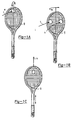
- the modes excited are the bending mode as illustrated in FIG. 1A, the torsional mode as illustrated in FIG. 1B and the longitudinal mode as illustrated in FIG. 1C.
- the longitudinal mode may be excited, for example, when the object such as a ball contacts the implement such as a tennis racquet during a serve.
- ⁇ is the excitation
- x 1 , x 2 , x 3 ... etc. are the mode shapes
- a 1 , a 2 , a 3 , etc. are the coefficients which dictate the contribution of each mode towards the total excitation.
- the energy from the impact excites the first frequency and the spin off energy will excite the second frequency and so on.
- the most probable modes that are subject to excitation are the first bending mode and first torsional mode. Nevertheless, the other modes get excited when there is enough energy generated during the impact.
- the present invention is a multi-mode vibration absorbing device for an implement including a base member at least partially disposed within the implement and a mass mounted to the base member and cantilevered relative to the base member.
- the device is tuned such that upon impact of the implement the mass generates energy and deforms the base member.
- the base member acts to absorb the energy generated by the mass and to release the absorbed energy to the implement to counteract energy produced in the implement due to impact.
- a multi-mode vibration absorbing device is provided for an implement in which the device itself is a vibrating system.
- the multi-mode vibration absorbing device vibrates at the same set of frequencies or multiple frequencies as the implement.
- the implement and multi-mode vibration absorbing device vibrate at the same set of frequencies and in a phase opposite to each other to cancel out each other and the resultant responses in the implement are reduced by a significant amount.
- the multi-mode vibration absorbing device absorbs energy at multiple frequencies of the implement due to impact.
- a further advantage of the present invention is that the multi-mode vibration absorbing device reduces vibrations in the implement due to impact and the human arm tends to absorb much less energy.
- FIG. 1A, 1B and 1C are perspective views of an implement illustrating bending, torsional and longitudinal modes of vibration respectfully.
- FIG. 2 is a perspective view of a multi-mode vibration absorbing device, according to the present invention, illustrated in operational relationship with an implement.
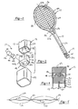
- FIG. 3 is an exploded view of the multi-mode vibration absorbing device and implement of FIG. 2.
- FIG. 4 is a fragmentary view of the multi-mode vibration absorbing device of FIG. 2.
- FIG. 5 is a schematic diagram illustrating vibratory motion of the multi-mode vibration absorbing device and implement of FIG. 2.
- FIG. 6 is a graph comparing relative frequency responses at handle between an undamped implement and a damped implement employing the multi-mode vibration absorbing device according to the present invention.
- FIG. 7 is an exploded view of another embodiment of the multi-mode vibration absorbing device and implement of FIG. 2.
- a multi-mode vibration absorbing device 10 for an implement, generally indicated at 12, such as a tennis racquet.
- the multi-mode vibration absorbing device 10 is employed to reduce multiple frequency vibrations in the implement 12.
- the implement 12 may be any suitable type of sporting implement such as a golf club, hockey stick or stringed racquet or hand operated implement such as a hammer or ax.
- the implement 12 in this example, generally includes a frame 13 having a head 14, strings 16, a throat 18 and a handle 20 as is known in the art. As illustrated in FIGS. 3 and 4, the racquet frame 13 has a reinforcement member 21 that divides the interior of the racquet frame 13 into two chambers. It should be appreciated that the racquet frame 13 is conventional and known in the art.
- the vibration absorbing device 10 is disposed in one end of the handle 20 to reduce multiple frequency vibrations in the implement 12.
- the vibration absorbing device 10 includes a base member 32 and a mass 34 mounted to the base member 32.
- the base member 32 has a body 35 which is generally rectangular in shape and has an outer surface 36 conforming to an interior surface 38 of the handle 20 to fit snugly therein.
- the base member 32 includes a projection 40 extending outwardly axially to divide the base member 32 into a first side 40a and a second side 40b.
- the projection 40 has a width less than a width of the body 35.
- the projection 40 also has an aperture 42 extending therethrough.
- the body 35 has a slot 43 at one end to receive the reinforcement member 21.
- the base member 32 is made of a visco-elastic material such as rubber. It should be appreciated that the multi-mode vibration absorbing device 10 may be tuned by placing the projection 40 at a non-central location of the base member 32 or by an unequal stiffness in first side 40a and second side 40b of the base member 32.
- the mass 34 is generally cylindrical in shape defining a longitudinal axis or shaft 44 and has a first head 46 at one end of the shaft 44 and a second head 48 at the other end of the shaft 44.
- the first head 46 and second head 48 are generally circular in cross-section.
- the mass 34 is made of a metal material such as brass.
- the properties of the base member 32 and the mass 34 are chosen such that the frequencies of the vibration absorbing device 10 are comparable to the same set of frequencies of the implement 12.
- the bending, torsional and longitudinal frequencies can be tuned by varying the length, width and thickness and material of the projection 40.
- the torsional frequency can be tuned, for example, by unequal distribution of the mass 34 such that the second head 48 has a diameter greater than the first head 46 or by placing the mass 34 at a non-central location relative to the base member 32.
- the mass 34 extends through the aperture 42 such that the projection 40 is disposed between the heads 46 and 48 and is cantilevered relative to the base member 32.
- a cap 49 is placed over the end of the handle 20 to enclose the vibration absorbing device 10.
- the cap 49 is made of a plastic material.
- the mass 34 and base member 32 and their geometries are tuned such that the vibration absorbing device 10 vibrates at the same set of frequencies as the implement 12 but out of phase therewith.
- the mass 34 vibrates one hundred eighty degrees (180°) out of phase with the implement 12.
- the base member 32 acts to absorb the energy at multiple frequencies generated by the mass 34 and to release the absorbed energy to the implement 12 to counteract energy produced in the implement 12 due to impact.
- the following dynamical description of the implement 12 and multi-mode vibration absorbing device 10 will include terms such as nodes and anti-nodes. It should be appreciated that the nodes/anti-nodes are defined when the implement 12 is not being held by a user.
- the bending mode vibrates in a pattern of, for example, two nodes and three anti-nodes.
- the anti-nodes are typically located at three places: an anti-node 51a located at the top of the implement 12; an anti-node 51b located at the intersection of the handle 20 and the head 14; and an anti-node 51c located at the end of the handle 20.
- the nodes are located in between the anti-nodes.
- the vibration damping device 10 has less effect when installed at the nodes and should be placed at the anti-nodes, preferably the anti-node 51c. In cases where this is not possible, the vibration damping device 10 should be placed as far away from the nodes as possible.
- the pattern of vibration for the torsional mode is a set of two anti-nodes 52 and 54 at each extreme side of the head 14 and a node line 56 at the center.
- the multi-mode vibration absorbing device 10 is located at the node line 56. When the implement 12 is held with a hand of the user, the node line 56 shifts laterally and is, therefore, located to properly damp vibrations of the implement 12.
- the resultant vibration in the implement 12 is dramatically reduced as indicated at 60 in FIG. 5.
- a graph of magnitude (dB) versus frequency (Hz) at the handle 20 is shown for an implement 12 without the multi-mode vibration absorbing device 10 (baseline) and with the multi-mode vibration absorbing device 10 (damped).
- a baseline curve 61 and damped curve 62 are illustrated.
- the peaks of the curves 61 and 62 represent the various modes.
- the peak of the baseline curve 61 for the implement 12 without the multi-mode vibration absorbing device 10 is significantly greater in magnitude than the peak for the damped curve 62 for the implement 12 with the multi-mode vibration absorbing device 10.
- the vibration absorbing device 110 is disposed in one end of the handle 20 to reduce multiple frequency vibrations in the implement 12.
- the vibration absorbing device 110 includes a base member 132 and a mass 134 mounted to the base member 132.
- the base member 132 has a body 135 which is generally cylindrical in shape and has an outer surface 136 conforming to an interior surface 38 of the handle 20 to fit snugly therein.
- the body 135 has an aperture 180 extending therethrough.
- the base member 132 is made of a high damping visco-elastic material such as rubber, foam or polyester.
- the mass 134 is generally cylindrical in shape and has a longitudinal axis.
- the mass 134 is generally circular in cross-section.
- the mass 134 is made of a metal material such as brass, steel or tungsten.
- the properties of the base member 132 and the mass 134 are chosen such that the frequencies of the vibration absorbing device 110 are comparable to the same set of frequencies of the implement 12.
- the bending, torsional and longitudinal frequencies can be tuned by varying the length, width and thickness and material of the base member 132 and mass 134.
- the mass 134 extends through the aperture 180 of the base member 132 such that the mass 134 is encapsulated.
- a cap 149 is placed over the end of the handle 20 to enclose the vibration absorbing device 110.
- the cap 149 is made of a plastic material.
- the mass 134 and base member 132 and their geometries are tuned such that the vibration absorbing device 110 vibrates at the same set of frequencies as the implement 12 but out of phase therewith.
- the mass 134 vibrates one hundred eighty degrees (180°) out of phase with the implement 12.
- the bending mode of the vibration absorbing device 110 occurs at the first bending mode of the implement 12.
- the torsional mode of the vibration absorbing device 110 occurs at the first torsional mode of the implement 12.
- the longitudinal mode of the vibration absorbing device 110 occurs at the first longitudinal mode of the implement 12.
- the base member 132 acts to absorb the energy at multiple frequencies generated by the mass 134 and to release the absorbed energy to the implement 12 to counteract energy produced in the implement 12 due to impact.
- the vibration absorbing device 110 reduces vibration of the implement as illustrated in FIG. 6. It should be appreciated that the corresponding modes of the vibration absorbing device 110 align with the corresponding modes of the implement 12.
Landscapes
- Health & Medical Sciences (AREA)
- General Health & Medical Sciences (AREA)
- Physical Education & Sports Medicine (AREA)
- Vibration Prevention Devices (AREA)
- Golf Clubs (AREA)
Abstract
A multi-mode vibration absorbing device for implements includes a base member and a mass mounted to the base member and cantilevered relative thereto. The multi-mode vibration absorbing device is tuned such that it vibrates at the same frequency as the implement but out of phase therewith.
Description
- The present invention relates generally to vibration absorbing devices and, more particularly, to a multi-mode vibration absorbing device for implements.
- The popularity of sports involving implements, such as golf, tennis, hockey and racquet ball, continues at a strong pace. Better engineering, better materials, lighter, stronger implements have improved the play of games with these implements and thereby increased the enjoyment associated therewith. Although these implements have worked well, they suffer from the disadvantage that, despite improvements in other areas, the unwanted vibratory phenomena generated upon an impact with an object which is not dead center in the "sweet spot" of the implement remains.
- Lighter implements have allowed players to swing harder at the object. Larger implements, while increasing the "sweet spot" thereof, have also increased the area outside the "sweet spot", providing increased opportunity for imperfect or offset contact with the object.
- For example, when an object impacts the implement, the implement excites in a fashion defined by the amount of force, location of impact and the dynamics of the implement structure. The magnitude and location of the impact 6 on the implement 8, as illustrated in FIGS. 1A, 1B and 1C, will cause either one or several modes to excite. Each of these modes will vibrate at a different frequency. The modes excited are the bending mode as illustrated in FIG. 1A, the torsional mode as illustrated in FIG. 1B and the longitudinal mode as illustrated in FIG. 1C. The longitudinal mode may be excited, for example, when the object such as a ball contacts the implement such as a tennis racquet during a serve.
- Any excitation is usually expressed as a linear combination of the dynamic modes of the implement as follows:

- Additionally, certain implements such as tennis racquets have increased in length, thereby lowering the natural frequencies of the racquets. For example, the second bending mode of the tennis racquet may have been lowered from five hundred hertz to three hundred hertz for a particular racquet. Thus, there is a need in the art to provide a vibration absorbing device for implements which will effectively damp out the vibrations caused by various modes at various frequencies due to impact.
- It is, therefore, one object of the present invention to provide a multi-mode vibration absorbing device for an implement.
- It is another object of the present invention to provide a multi-mode vibration absorbing device for an implement which effectively cancels vibration generated by unbalance forces due to an off center contact with an object.
- It is yet another object of the present invention to provide a multi-mode vibration absorbing device which absorbs energy at multiple frequencies of an implement due to impact.
- To achieve the foregoing objects, the present invention is a multi-mode vibration absorbing device for an implement including a base member at least partially disposed within the implement and a mass mounted to the base member and cantilevered relative to the base member. The device is tuned such that upon impact of the implement the mass generates energy and deforms the base member. The base member acts to absorb the energy generated by the mass and to release the absorbed energy to the implement to counteract energy produced in the implement due to impact.
- One advantage of the present invention is that a multi-mode vibration absorbing device is provided for an implement in which the device itself is a vibrating system. Another advantage of the present invention is that the multi-mode vibration absorbing device vibrates at the same set of frequencies or multiple frequencies as the implement. Yet another advantage of the present invention is that the implement and multi-mode vibration absorbing device vibrate at the same set of frequencies and in a phase opposite to each other to cancel out each other and the resultant responses in the implement are reduced by a significant amount. Still another advantage of the present invention is that the multi-mode vibration absorbing device absorbs energy at multiple frequencies of the implement due to impact. A further advantage of the present invention is that the multi-mode vibration absorbing device reduces vibrations in the implement due to impact and the human arm tends to absorb much less energy.
- Other objects, features and advantages of the present invention will be readily appreciated as the same becomes better understood after reading the subsequent description taken in conjunction with the accompanying drawings, which are by way of example only.
- FIG. 1A, 1B and 1C are perspective views of an implement illustrating bending, torsional and longitudinal modes of vibration respectfully.
- FIG. 2 is a perspective view of a multi-mode vibration absorbing device, according to the present invention, illustrated in operational relationship with an implement.
- FIG. 3 is an exploded view of the multi-mode vibration absorbing device and implement of FIG. 2.
- FIG. 4 is a fragmentary view of the multi-mode vibration absorbing device of FIG. 2.
- FIG. 5 is a schematic diagram illustrating vibratory motion of the multi-mode vibration absorbing device and implement of FIG. 2.
- FIG. 6 is a graph comparing relative frequency responses at handle between an undamped implement and a damped implement employing the multi-mode vibration absorbing device according to the present invention.
- FIG. 7 is an exploded view of another embodiment of the multi-mode vibration absorbing device and implement of FIG. 2.
- Referring to the drawings and in particular to FIG. 2, one embodiment of a multi-mode
vibration absorbing device 10, according to the present invention, is shown for an implement, generally indicated at 12, such as a tennis racquet. The multi-modevibration absorbing device 10 is employed to reduce multiple frequency vibrations in theimplement 12. It should be appreciated that theimplement 12 may be any suitable type of sporting implement such as a golf club, hockey stick or stringed racquet or hand operated implement such as a hammer or ax. - The
implement 12, in this example, generally includes aframe 13 having ahead 14,strings 16, a throat 18 and ahandle 20 as is known in the art. As illustrated in FIGS. 3 and 4, theracquet frame 13 has areinforcement member 21 that divides the interior of theracquet frame 13 into two chambers. It should be appreciated that theracquet frame 13 is conventional and known in the art. - Referring to FIGS. 2 through 4, the multi-mode
vibration absorbing device 10 is disposed in one end of thehandle 20 to reduce multiple frequency vibrations in theimplement 12. Thevibration absorbing device 10 includes abase member 32 and amass 34 mounted to thebase member 32. Thebase member 32 has abody 35 which is generally rectangular in shape and has anouter surface 36 conforming to aninterior surface 38 of thehandle 20 to fit snugly therein. Thebase member 32 includes aprojection 40 extending outwardly axially to divide thebase member 32 into a first side 40a and a second side 40b. Theprojection 40 has a width less than a width of thebody 35. Theprojection 40 also has anaperture 42 extending therethrough. Thebody 35 has aslot 43 at one end to receive thereinforcement member 21. Thebase member 32 is made of a visco-elastic material such as rubber. It should be appreciated that the multi-modevibration absorbing device 10 may be tuned by placing theprojection 40 at a non-central location of thebase member 32 or by an unequal stiffness in first side 40a and second side 40b of thebase member 32. - The
mass 34 is generally cylindrical in shape defining a longitudinal axis orshaft 44 and has afirst head 46 at one end of theshaft 44 and asecond head 48 at the other end of theshaft 44. Preferably, thefirst head 46 andsecond head 48 are generally circular in cross-section. Themass 34 is made of a metal material such as brass. The properties of thebase member 32 and themass 34 are chosen such that the frequencies of thevibration absorbing device 10 are comparable to the same set of frequencies of theimplement 12. The bending, torsional and longitudinal frequencies can be tuned by varying the length, width and thickness and material of theprojection 40. The torsional frequency can be tuned, for example, by unequal distribution of themass 34 such that thesecond head 48 has a diameter greater than thefirst head 46 or by placing themass 34 at a non-central location relative to thebase member 32. - The
mass 34 extends through theaperture 42 such that theprojection 40 is disposed between theheads base member 32. Acap 49 is placed over the end of thehandle 20 to enclose thevibration absorbing device 10. Thecap 49 is made of a plastic material. Themass 34 andbase member 32 and their geometries are tuned such that thevibration absorbing device 10 vibrates at the same set of frequencies as the implement 12 but out of phase therewith. Themass 34 vibrates one hundred eighty degrees (180°) out of phase with the implement 12. Thebase member 32 acts to absorb the energy at multiple frequencies generated by themass 34 and to release the absorbed energy to the implement 12 to counteract energy produced in the implement 12 due to impact. - The following dynamical description of the implement 12 and multi-mode
vibration absorbing device 10 will include terms such as nodes and anti-nodes. It should be appreciated that the nodes/anti-nodes are defined when the implement 12 is not being held by a user. - Assuming the impact location is offset by a large distance and the impact force is large, the bending mode vibrates in a pattern of, for example, two nodes and three anti-nodes. The anti-nodes are typically located at three places: an anti-node 51a located at the top of the implement 12; an anti-node 51b located at the intersection of the
handle 20 and thehead 14; and an anti-node 51c located at the end of thehandle 20. The nodes are located in between the anti-nodes. Thevibration damping device 10 has less effect when installed at the nodes and should be placed at the anti-nodes, preferably the anti-node 51c. In cases where this is not possible, thevibration damping device 10 should be placed as far away from the nodes as possible. - Assuming the impact location is offset by a large distance and also the impact force is large, the excitations cause the implement 12 to vibrate at more than one frequency at bending and torsional modes. Although the amount of vibration due to each mode cannot be identified accurately, the vibration effects are felt by the user. The pattern of vibration for the torsional mode is a set of two
anti-nodes head 14 and anode line 56 at the center. The multi-modevibration absorbing device 10 is located at thenode line 56. When the implement 12 is held with a hand of the user, thenode line 56 shifts laterally and is, therefore, located to properly damp vibrations of the implement 12. When properly damped using the multi-modevibration absorbing device 10 of the present invention, the resultant vibration in the implement 12 is dramatically reduced as indicated at 60 in FIG. 5. - Referring to FIG. 6, a graph of magnitude (dB) versus frequency (Hz) at the
handle 20 is shown for an implement 12 without the multi-mode vibration absorbing device 10 (baseline) and with the multi-mode vibration absorbing device 10 (damped). Abaseline curve 61 and dampedcurve 62 are illustrated. The peaks of thecurves baseline curve 61 for the implement 12 without the multi-modevibration absorbing device 10 is significantly greater in magnitude than the peak for thedamped curve 62 for the implement 12 with the multi-modevibration absorbing device 10. - Referring to FIG. 7, another embodiment 110 of the multi-mode
vibration absorbing device 10 is shown. Like parts of thevibration absorbing device 10 have like reference numerals increased by one hundred (100). The vibration absorbing device 110 is disposed in one end of thehandle 20 to reduce multiple frequency vibrations in the implement 12. The vibration absorbing device 110 includes a base member 132 and amass 134 mounted to the base member 132. The base member 132 has abody 135 which is generally cylindrical in shape and has an outer surface 136 conforming to aninterior surface 38 of thehandle 20 to fit snugly therein. Thebody 135 has anaperture 180 extending therethrough. The base member 132 is made of a high damping visco-elastic material such as rubber, foam or polyester. - The
mass 134 is generally cylindrical in shape and has a longitudinal axis. Themass 134 is generally circular in cross-section. Themass 134 is made of a metal material such as brass, steel or tungsten. The properties of the base member 132 and themass 134 are chosen such that the frequencies of the vibration absorbing device 110 are comparable to the same set of frequencies of the implement 12. The bending, torsional and longitudinal frequencies can be tuned by varying the length, width and thickness and material of the base member 132 andmass 134. - The
mass 134 extends through theaperture 180 of the base member 132 such that themass 134 is encapsulated. Acap 149 is placed over the end of thehandle 20 to enclose the vibration absorbing device 110. Thecap 149 is made of a plastic material. Themass 134 and base member 132 and their geometries are tuned such that the vibration absorbing device 110 vibrates at the same set of frequencies as the implement 12 but out of phase therewith. Themass 134 vibrates one hundred eighty degrees (180°) out of phase with the implement 12. The bending mode of the vibration absorbing device 110 occurs at the first bending mode of the implement 12. The torsional mode of the vibration absorbing device 110 occurs at the first torsional mode of the implement 12. The longitudinal mode of the vibration absorbing device 110 occurs at the first longitudinal mode of the implement 12. The base member 132 acts to absorb the energy at multiple frequencies generated by themass 134 and to release the absorbed energy to the implement 12 to counteract energy produced in the implement 12 due to impact. The vibration absorbing device 110 reduces vibration of the implement as illustrated in FIG. 6. It should be appreciated that the corresponding modes of the vibration absorbing device 110 align with the corresponding modes of the implement 12. - The present invention has been described in an illustrative manner. It is to be understood that the terminology which has been used is intended to be in the nature of words of description rather than of limitation.
- Many modifications and variations of the present invention are possible in light of the above teachings. Therefore, within the scope of the appended claims, the present invention may be practiced other than as specifically described.
Claims (10)
- A multi-mode vibration absorbing device for an implement comprising:a base member;a mass mounted to said base member and cantilevered relative to said base member, said device being tuned such that it vibrates at substantially the same set of frequencies as the implement but out of phase therewith.
- A multi-mode vibration absorbing device as set forth in claim 1, wherein said base member has an aperture extending therethrough, said mass extending through said aperture in said base member; and/or
wherein said mass includes a shaft having a first head at one end and a second head at the other end, said first head preferably being larger than said second head. - A multi-mode vibration absorbing device as set forth in claim 1 or claim 2, wherein said base member has a body and a projection extending outwardly from said body, said projection preferably being offset relative to a centreline of said body; and/or wherein an aperture extends through said projection of said base member, said mass extending through said aperture.
- A multi-mode vibration absorbing device as set forth in any preceding claim, wherein said body has first and second sides of unequal stiffness; and/or
said body has a recess for receiving a portion of the implement. - A multi-mode vibration absorbing device as set forth in any preceding claim, wherein said multi-mode vibration absorbing device is mounted in a handle of the implement.
- An implement comprising:a frame including a head and a handle;a multi-mode vibration absorbing device mounted in said handle of said implement and including a viscoelastic base member and a mass mounted to said viscoelastic base member and cantilevered relative to said viscoelastic base member, said device being tuned such that it vibrates at substantially the same frequency as said implement but out of phase therewith.
- An implement as set forth in claim 6, wherein said multi-mode vibration absorbing device is disposed at the end of said handle opposite said head; and/or
said viscoelastic base member has an aperture extending therethrough, said mass extending through said aperture. - An implement as set forth in claim 6 or claim 7, wherein said mass includes a shaft having a first head at one end and a second head at the other end, said first head preferably being larger than said second head.
- An implement as set forth in any of claims 6 to 8, wherein said base member has a body and a projection extending outwardly from said body, said projection preferably being offset relative to a centreline of said body; and/or
said body having first and second sides of unequal stiffness. - An implement as set forth in any of claims 6 to 9, wherein said mass is cylindrical in shape; and/or
wherein said base member extends longitudinally and has an aperture extending therethrough, said mass being disposed in said aperture and being encapsulated by said base member.
Applications Claiming Priority (2)
| Application Number | Priority Date | Filing Date | Title |
|---|---|---|---|
| US580297 | 1995-12-28 | ||
| US08/580,297 US5935027A (en) | 1995-12-28 | 1995-12-28 | Multi-mode vibration absorbing device for implements |
Publications (2)
| Publication Number | Publication Date |
|---|---|
| EP0781575A2 true EP0781575A2 (en) | 1997-07-02 |
| EP0781575A3 EP0781575A3 (en) | 1999-03-24 |
Family
ID=24320522
Family Applications (1)
| Application Number | Title | Priority Date | Filing Date |
|---|---|---|---|
| EP96303055A Withdrawn EP0781575A3 (en) | 1995-12-28 | 1996-05-01 | Multi-mode vibration absorbing device |
Country Status (3)
| Country | Link |
|---|---|
| US (2) | US5935027A (en) |
| EP (1) | EP0781575A3 (en) |
| JP (1) | JPH09196112A (en) |
Cited By (5)
| Publication number | Priority date | Publication date | Assignee | Title |
|---|---|---|---|---|
| WO1999011332A2 (en) * | 1997-08-28 | 1999-03-11 | Head Sport Aktiengesellschaft | Lightweight tennis racket having high frequency |
| EP0898986A3 (en) * | 1997-08-28 | 1999-03-31 | Head Sport Aktiengesellschaft | Vibration damping device of a racket |
| WO1999026701A1 (en) * | 1997-11-25 | 1999-06-03 | Minnesota Mining And Manufacturing Company | Vibration damped ball bats |
| FR2789320A1 (en) * | 1999-02-04 | 2000-08-11 | Jean Claude Bianchi | Vibration damper for tennis racquet has flexible plate fixed to cords and having projection which rotates to dampen vibration |
| US6447411B1 (en) | 1999-02-04 | 2002-09-10 | Jean-Claude Bianchi | Vibration damper using a rotary mechanism for all tennis rackets |
Families Citing this family (13)
| Publication number | Priority date | Publication date | Assignee | Title |
|---|---|---|---|---|
| US5935027A (en) * | 1995-12-28 | 1999-08-10 | Roush Anatrol, Inc. | Multi-mode vibration absorbing device for implements |
| DE29822451U1 (en) * | 1998-12-17 | 1999-04-01 | You, Chin-San, Feng Yuan, Taichung | Shock absorber for a ball game article with a tubular body |
| AU755586B2 (en) * | 1998-12-24 | 2002-12-19 | Chin-San You | Shock absorbing device for use in ballgame goods having tubular rod-shaped body |
| US7963868B2 (en) | 2000-09-15 | 2011-06-21 | Easton Sports, Inc. | Hockey stick |
| CA2364919A1 (en) * | 2000-12-14 | 2002-06-14 | Kevin Tuer | Proprioceptive golf club with analysis, correction and control capabilities |
| US6673100B2 (en) * | 2001-05-25 | 2004-01-06 | Cordis Neurovascular, Inc. | Method and device for retrieving embolic coils |
| US7669397B1 (en) | 2002-03-20 | 2010-03-02 | The Toro Company | Reel mower with tuned mass damper |
| US7007448B2 (en) * | 2002-03-20 | 2006-03-07 | The Toro Company | Reel mower with tuned mass damper |
| US7232386B2 (en) | 2003-05-15 | 2007-06-19 | Easton Sports, Inc. | Hockey stick |
| JP4444731B2 (en) * | 2004-05-18 | 2010-03-31 | Sriスポーツ株式会社 | Racket frame |
| WO2007059335A2 (en) * | 2005-11-16 | 2007-05-24 | Easton Sports, Inc. | Hockey stick |
| US7914403B2 (en) | 2008-08-06 | 2011-03-29 | Easton Sports, Inc. | Hockey stick |
| WO2015143306A1 (en) * | 2014-03-20 | 2015-09-24 | Bruce Wright | Articulated butt end improvement on handheld rackets, bats and clubs |
Family Cites Families (102)
| Publication number | Priority date | Publication date | Assignee | Title |
|---|---|---|---|---|
| GB191213337A (en) * | 1912-02-06 | 1913-06-06 | Voester & Widmann Vorm O Tourn | Improvements in or connected with Internal Combustion Engines. |
| US1169667A (en) * | 1915-04-13 | 1916-01-25 | William Henry Meguyer | Golf-club. |
| US1894706A (en) * | 1928-07-06 | 1933-01-17 | Spalding & Bros Ag | Golf club with metallic shaft and hosel |
| US1906239A (en) * | 1928-07-06 | 1933-05-02 | Spalding & Bros Ag | Golf club |
| US1777822A (en) * | 1928-09-26 | 1930-10-07 | Pyratone Products Corp | Golf-club shaft |
| US1980408A (en) * | 1929-09-19 | 1934-11-13 | Wilson Western Sporting Goods | Golf club |
| US1894707A (en) * | 1931-01-13 | 1933-01-17 | Spalding & Bros Ag | Golf club with metallic shaft and hosel |
| US1953604A (en) * | 1931-09-22 | 1934-04-03 | Paul E Heller | Golf club |
| US1946007A (en) * | 1931-10-27 | 1934-02-06 | Samuel E Watson | Golf club |
| US1968616A (en) * | 1931-12-31 | 1934-07-31 | Leonard A Young | Golf club shaft |
| US2023131A (en) * | 1932-09-05 | 1935-12-03 | Gibson Robert James | Steel shaft for golf clubs |
| GB434533A (en) * | 1934-03-07 | 1935-09-04 | Frank Macallum | Improvements in golf clubs |
| US2099319A (en) * | 1934-07-12 | 1937-11-16 | Shaw David Mackintosh | Grip, handle, or shaft of percussive or swinging implements |
| US2129068A (en) * | 1934-08-25 | 1938-09-06 | Spalding & Bros Ag | Golf club |
| GB499155A (en) * | 1937-11-03 | 1939-01-19 | Castle Golf Company Ltd | Improvements in and relating to golf clubs |
| US2451217A (en) * | 1945-04-06 | 1948-10-12 | Auto Diesel Piston Ring Compan | Shock absorbing hammer |
| US2603260A (en) * | 1948-01-10 | 1952-07-15 | Axel E Floren | Hammer having shock-absorbing handle |
| US2737216A (en) * | 1953-12-23 | 1956-03-06 | Metocraft Alloy Corp | Recoil-less hammer head construction |
| US2928444A (en) * | 1958-07-08 | 1960-03-15 | Olin Mathieson | Shockless hammer |
| US3089525A (en) * | 1960-10-07 | 1963-05-14 | John P Palmer | Tool handle |
| US3075768A (en) * | 1960-10-31 | 1963-01-29 | Fawick Flexi Grip Company | Weighted golf club and method of weighting same |
| US3030989A (en) * | 1961-01-25 | 1962-04-24 | Olin Mathieson | Hammer |
| US3208724A (en) * | 1963-12-16 | 1965-09-28 | Vaughan & Bushnell Mfg Co | Carpenter's claw hammer with vibration dampening means |
| US3613753A (en) * | 1969-04-21 | 1971-10-19 | Vaughan & Bushnell Mfg Co | Hollow hammer handle with longitudinally tensioned glass fibers |
| US3844321A (en) * | 1971-06-22 | 1974-10-29 | Custom Electronic Syst Inc | Unitarily cast hammer |
| US3764137A (en) * | 1972-06-09 | 1973-10-09 | A Petro | Combination stiff and flexible golf club shaft |
| US3941380A (en) * | 1972-07-31 | 1976-03-02 | Patentex S.A. | Tennis rackets and similar implements with vibration damper |
| US4023801A (en) * | 1974-09-24 | 1977-05-17 | Exxon Research And Engineering Company | Golf shaft and method of making same |
| US3972529A (en) * | 1974-10-07 | 1976-08-03 | Mcneil Walter F | Reinforced tubular materials and process |
| US4085784A (en) * | 1975-06-26 | 1978-04-25 | Fish Herbert L | Impact tool and handle assembly therefor |
| US4044625A (en) * | 1976-07-01 | 1977-08-30 | Chicago Pneumatic Tool Company | Vibration isolating hand grip for shank of a percussive chisel |
| ZA784458B (en) * | 1978-08-07 | 1979-12-27 | Modern Inventions Ltd | Handle |
| GB2053004A (en) * | 1979-06-21 | 1981-02-04 | Accles & Pollock Ltd | Golf club shafts |
| GB2053698B (en) * | 1979-07-25 | 1983-02-02 | Dunlop Ltd | Golf club |
| US4353551A (en) * | 1979-07-26 | 1982-10-12 | Battelle Development Corporation | Tennis racket with frame mounted oscillatable weights |
| US4287640A (en) * | 1979-08-17 | 1981-09-08 | Ixl Manufacturing Co., Inc. | Tool handle and method of making same |
| US4415156A (en) * | 1981-08-26 | 1983-11-15 | Jorgensen Theodore P | Matched set of golf clubs |
| US4498464A (en) * | 1982-06-21 | 1985-02-12 | Morgan Jr Darrell W | Chiropractic instrument |
| US4627635A (en) * | 1983-09-20 | 1986-12-09 | Koleda Michael T | Vibration damping units and vibration damped products |
| US4555112A (en) * | 1983-09-22 | 1985-11-26 | Wilson Sporting Goods Company | Golf club shafts with matched frequencies of vibration |
| US4541631A (en) * | 1983-10-03 | 1985-09-17 | Sasse Howard A | Golf club |
| US4690405A (en) * | 1983-10-19 | 1987-09-01 | Frolow Jack L | Tennis racket |
| US4799375A (en) * | 1983-10-26 | 1989-01-24 | Pcb Piezotronics, Inc. | Instrumented test hammer |
| US4609198A (en) * | 1983-11-08 | 1986-09-02 | Tarr Robert G | Racket handle assembly having vibration dampening characteristics |
| US4674746A (en) * | 1984-03-27 | 1987-06-23 | Benoit William R | Golf club |
| FR2575393A1 (en) * | 1984-12-27 | 1986-07-04 | Rossignol Sa | SNOW SKI |
| ZA851343B (en) * | 1985-02-22 | 1985-10-30 | Patrick Arthur Lamont | Hammer and handle |
| US4660832A (en) * | 1985-03-25 | 1987-04-28 | Shomo Robert D | Shock and vibration absorbent handle |
| JPH0640904B2 (en) * | 1985-05-27 | 1994-06-01 | 住友ゴム工業株式会社 | Golf club set |
| JPH0532142Y2 (en) * | 1985-10-16 | 1993-08-18 | ||
| DE3704121A1 (en) * | 1986-02-19 | 1987-08-20 | Nippon Musical Instruments Mfg | VIBRATION ABSORBER FOR A ROCKET |
| US4721021A (en) * | 1986-09-10 | 1988-01-26 | Kusznir Phillip S | Handle structure |
| FR2608444B1 (en) * | 1986-12-22 | 1989-03-31 | Rossignol Sa | TENNIS RACKET |
| US4753137A (en) * | 1987-04-01 | 1988-06-28 | Kennedy Thomas W | Hand tool, such as a sledgehammer, with replaceable head |
| FR2615113A1 (en) * | 1987-05-13 | 1988-11-18 | Boschian Louis | IMPROVEMENT TO VIBRATION ATTENUATORS FOR TENNIS RACKETS |
| BE1000688A6 (en) * | 1987-07-14 | 1989-03-14 | Donnay Donnay S A Ets | Racket handle. |
| US4826167A (en) * | 1988-01-05 | 1989-05-02 | Lo Pi Tuan | Racket having a cushioning shaft portion |
| JP2598675B2 (en) * | 1988-05-14 | 1997-04-09 | 株式会社シーゲル | racket |
| JPH0231770A (en) * | 1988-07-20 | 1990-02-01 | Mizuno Corp | Shaft for golf club |
| US4979743A (en) * | 1988-08-12 | 1990-12-25 | Sears Gerard A | Golf club grip |
| US4836545A (en) * | 1988-11-07 | 1989-06-06 | Pompa J Benedict | Two piece metallic and composite golf shaft |
| GB2226380A (en) * | 1988-12-22 | 1990-06-27 | John Peter Booth | Tapered tubular composite shafts |
| JPH0790044B2 (en) * | 1989-01-20 | 1995-10-04 | マルマンゴルフ株式会社 | Golf club set |
| US5083780A (en) * | 1989-03-28 | 1992-01-28 | Spalding & Evenflo Companies, Inc. | Golf club shaft having selective reinforcement |
| US4951948A (en) * | 1989-04-17 | 1990-08-28 | Peng Jung C | Shock absorbing bat |
| JPH0755239B2 (en) * | 1989-07-18 | 1995-06-14 | 鈴木総業株式会社 | Exercise equipment for hitting balls |
| US5314180A (en) * | 1989-08-28 | 1994-05-24 | Toray Industries, Inc. | Sports instrument and impact-absorbing element to be attached to sports equipment |
| US4951953A (en) * | 1990-02-15 | 1990-08-28 | Kim Dong S T | Golf club |
| US5236198A (en) * | 1990-05-02 | 1993-08-17 | Dunlop Limited | Games racket frame |
| US5039096A (en) * | 1990-05-02 | 1991-08-13 | Dennis Chen | Shock absorbing racket |
| US5297791A (en) * | 1990-06-04 | 1994-03-29 | Fujikura Rubber Ltd. | Golf club shaft and method of producing the same |
| JPH0420371U (en) * | 1990-06-08 | 1992-02-20 | ||
| US5094453A (en) * | 1990-07-25 | 1992-03-10 | Douglas Preston L | Ball bat with inward off-set center of gravity |
| US5131652A (en) * | 1991-01-25 | 1992-07-21 | Peng Jung Ching | Shock absorbing racket handle |
| JPH04263876A (en) * | 1991-02-18 | 1992-09-18 | Toray Ind Inc | Grip end, sport goods and bicycle in which the same is installed, and tool therefor |
| US5092594A (en) * | 1991-02-21 | 1992-03-03 | Yea Tay Enterprise Co., Ltd. | Shock absorbing structures of a game racket handle |
| US5141228A (en) * | 1991-04-19 | 1992-08-25 | Soong Tsai C | Shock absorbing string post for sports rackets |
| US5180163A (en) * | 1991-04-22 | 1993-01-19 | Lanctot Paul A | Baseball bat |
| US5219164A (en) * | 1991-05-31 | 1993-06-15 | Peng Jung Ching | Shock absorbing baseball bat |
| US5375486A (en) * | 1991-06-10 | 1994-12-27 | Carmien; Joseph A. | Surface protective striking tools |
| DE4134972A1 (en) * | 1991-07-27 | 1993-04-29 | Roland Sommer | TENNIS RACKET WITH IMPROVED VIBRATION DAMPING AND RESPONSE IMPULSES AND WITH INCREASING STRENGTH AND METHOD FOR THE PRODUCTION THEREFORE TAKING INTO ACCOUNT THE RUN OF AN AUTOMATED MANUFACTURING METHOD |
| FR2680694A1 (en) * | 1991-08-28 | 1993-03-05 | Rossignol Sa | VIBRATION DAMPING DEVICE FOR HANDLE INSTRUMENT AND HITTING HEAD. |
| JP2853926B2 (en) * | 1991-09-24 | 1999-02-03 | 東レ株式会社 | Impact vibration absorbing member and grip end of sports equipment, grip end of tool and grip end of motorcycle using the same |
| FR2681791B1 (en) * | 1991-09-27 | 1994-05-06 | Salomon Sa | VIBRATION DAMPING DEVICE FOR A GOLF CLUB. |
| CA2057180C (en) * | 1991-12-11 | 1998-06-30 | Chin-San You | Shock-absorbing racket frame made from fiber reinforced plastic material |
| US5269516A (en) * | 1991-12-30 | 1993-12-14 | Gencorp Inc. | Racquet handle |
| US5203561A (en) * | 1992-04-08 | 1993-04-20 | Lanctot Paul A | Vibration dampening handle having metal particles and a viscus fluid |
| US5303917A (en) * | 1992-04-13 | 1994-04-19 | Uke Alan K | Bat for baseball or softball |
| US5282618A (en) * | 1992-06-25 | 1994-02-01 | Bonny Sports Corp. | Racket with improved shock-absorbing means |
| TW286290B (en) * | 1992-07-16 | 1996-09-21 | Minnesota Mining & Mfg | |
| US5259274A (en) * | 1992-07-28 | 1993-11-09 | The Stanley Works | Hand tool with internally reinforced jacketed handle |
| US5280739A (en) * | 1992-12-03 | 1994-01-25 | Liou Mou T | Handle of a hammer having a shock absorbing configuration |
| US5289742A (en) * | 1992-12-22 | 1994-03-01 | Vaughan & Bushnell Manufacturing Co. | Vibration damping device for hammers |
| US5380003A (en) * | 1993-01-15 | 1995-01-10 | Lanctot; Paul A. | Baseball bat |
| US5362046A (en) * | 1993-05-17 | 1994-11-08 | Steven C. Sims, Inc. | Vibration damping |
| FR2706777A1 (en) * | 1993-06-21 | 1994-12-30 | Taylor Made Golf Co | Golf-club shaft (handle) with optimised distribution of flexibility |
| US5322280A (en) * | 1993-06-28 | 1994-06-21 | Jan Sports Products Corp. | Racket handle |
| US5409218A (en) * | 1994-01-07 | 1995-04-25 | You; Chin-San | Metal game racket |
| US5511777A (en) * | 1994-02-03 | 1996-04-30 | Grover Products Co. | Ball bat with rebound core |
| US5408902A (en) * | 1994-03-10 | 1995-04-25 | Burnett John A | Composite percussive tool |
| US5651545A (en) * | 1995-06-07 | 1997-07-29 | Roush Anatrol, Inc. | Vibration damping device for stringed racquets |
| US5935027A (en) * | 1995-12-28 | 1999-08-10 | Roush Anatrol, Inc. | Multi-mode vibration absorbing device for implements |
-
1995
- 1995-12-28 US US08/580,297 patent/US5935027A/en not_active Expired - Fee Related
-
1996
- 1996-05-01 EP EP96303055A patent/EP0781575A3/en not_active Withdrawn
- 1996-06-14 JP JP8153523A patent/JPH09196112A/en active Pending
-
1998
- 1998-05-13 US US09/078,170 patent/US6203454B1/en not_active Expired - Fee Related
Non-Patent Citations (1)
| Title |
|---|
| None |
Cited By (7)
| Publication number | Priority date | Publication date | Assignee | Title |
|---|---|---|---|---|
| US6106417A (en) * | 1995-08-22 | 2000-08-22 | Head Sport Aktiengesellschaft | Lightweight tennis racket having high frequency |
| WO1999011332A2 (en) * | 1997-08-28 | 1999-03-11 | Head Sport Aktiengesellschaft | Lightweight tennis racket having high frequency |
| EP0898986A3 (en) * | 1997-08-28 | 1999-03-31 | Head Sport Aktiengesellschaft | Vibration damping device of a racket |
| WO1999011332A3 (en) * | 1997-08-28 | 1999-07-08 | Head Sport Ag | Lightweight tennis racket having high frequency |
| WO1999026701A1 (en) * | 1997-11-25 | 1999-06-03 | Minnesota Mining And Manufacturing Company | Vibration damped ball bats |
| FR2789320A1 (en) * | 1999-02-04 | 2000-08-11 | Jean Claude Bianchi | Vibration damper for tennis racquet has flexible plate fixed to cords and having projection which rotates to dampen vibration |
| US6447411B1 (en) | 1999-02-04 | 2002-09-10 | Jean-Claude Bianchi | Vibration damper using a rotary mechanism for all tennis rackets |
Also Published As
| Publication number | Publication date |
|---|---|
| US5935027A (en) | 1999-08-10 |
| US6203454B1 (en) | 2001-03-20 |
| EP0781575A3 (en) | 1999-03-24 |
| JPH09196112A (en) | 1997-07-29 |
Similar Documents
| Publication | Publication Date | Title |
|---|---|---|
| US5655980A (en) | Vibration damping device for sporting implements | |
| US5935027A (en) | Multi-mode vibration absorbing device for implements | |
| US5655975A (en) | Golf club having vibration damping device and method for making same | |
| US5772541A (en) | Vibration dampened hand-held implements | |
| US6592468B2 (en) | Golf club head | |
| EP1894681B1 (en) | A Manually Operable Impact Tool and a Method for Making a Manually Operable Impact Tool | |
| US4660832A (en) | Shock and vibration absorbent handle | |
| US4180265A (en) | Implement for striking a ball | |
| US7178428B2 (en) | Impact instrument | |
| JP2617644B2 (en) | Racket for ball games | |
| JP3220417B2 (en) | Vibration damping inserts for golf clubs | |
| US6354958B1 (en) | Vibration damper for a golf club | |
| EP0317711B1 (en) | Racket for playing a game with a ball | |
| US6953405B2 (en) | Vibration damping field hockey stick | |
| US6863628B1 (en) | Vibration damping striking implement | |
| US5788586A (en) | Golf club having vibration damping device and method for making same | |
| US5110125A (en) | Sport racket | |
| JP2853926B2 (en) | Impact vibration absorbing member and grip end of sports equipment, grip end of tool and grip end of motorcycle using the same | |
| US20180361215A1 (en) | Shock and vibration absorbing system for baseball and softball bats | |
| GB2251387A (en) | Racket frame | |
| EP0032506A1 (en) | Tennis racket. | |
| US20050272536A1 (en) | Racket frame | |
| JPH02261479A (en) | Stroking goods and racket frame | |
| JP2000024140A (en) | Vibration damper | |
| JP4615674B2 (en) | Racket frame |
Legal Events
| Date | Code | Title | Description |
|---|---|---|---|
| PUAI | Public reference made under article 153(3) epc to a published international application that has entered the european phase |
Free format text: ORIGINAL CODE: 0009012 |
|
| AK | Designated contracting states |
Kind code of ref document: A2 Designated state(s): DE ES FR GB |
|
| PUAL | Search report despatched |
Free format text: ORIGINAL CODE: 0009013 |
|
| AK | Designated contracting states |
Kind code of ref document: A3 Designated state(s): DE ES FR GB |
|
| 17P | Request for examination filed |
Effective date: 19990914 |
|
| STAA | Information on the status of an ep patent application or granted ep patent |
Free format text: STATUS: THE APPLICATION IS DEEMED TO BE WITHDRAWN |
|
| 18D | Application deemed to be withdrawn |
Effective date: 20021203 |