EP0781521A1 - Dispenser for a personal hygiene liquid - Google Patents
Dispenser for a personal hygiene liquid Download PDFInfo
- Publication number
- EP0781521A1 EP0781521A1 EP96203617A EP96203617A EP0781521A1 EP 0781521 A1 EP0781521 A1 EP 0781521A1 EP 96203617 A EP96203617 A EP 96203617A EP 96203617 A EP96203617 A EP 96203617A EP 0781521 A1 EP0781521 A1 EP 0781521A1
- Authority
- EP
- European Patent Office
- Prior art keywords
- liquid
- container
- conduit
- valve
- dispenser according
- Prior art date
- Legal status (The legal status is an assumption and is not a legal conclusion. Google has not performed a legal analysis and makes no representation as to the accuracy of the status listed.)
- Granted
Links
Images


Classifications
-
- A—HUMAN NECESSITIES
- A47—FURNITURE; DOMESTIC ARTICLES OR APPLIANCES; COFFEE MILLS; SPICE MILLS; SUCTION CLEANERS IN GENERAL
- A47K—SANITARY EQUIPMENT NOT OTHERWISE PROVIDED FOR; TOILET ACCESSORIES
- A47K5/00—Holders or dispensers for soap, toothpaste, or the like
- A47K5/06—Dispensers for soap
- A47K5/12—Dispensers for soap for liquid or pasty soap
- A47K5/1211—Dispensers for soap for liquid or pasty soap using pressure on soap, e.g. with piston
- A47K5/1214—Dispensers for soap for liquid or pasty soap using pressure on soap, e.g. with piston applied by gravitational force
Definitions
- the present invention relates to dispensers for a personal hygiene liquid and, more particularly, to gravity fed liquid dispensers having a constant flow rate, comprising a container for the liquid, which liquid has a level situated at a first height, a liquid outlet situated at a second height lower than the first height, a conduit for allowing flow of liquid from said container to said liquid outlet in response to hydrostatic pressure of the liquid, and a valve for controlling the flow of liquid through said outlet.
- Gravity fed liquid dispensers suffer from a common problem of diminishing flow rate as a function of the lowering fluid level within the dispenser.
- One technique for solving this problem is set forth in EP-B-0 127 497.
- liquid soap is disposed within a flexible container. Outflow of the liquid soap is provided by a conduit defining an outlet and a valve controls flow through the conduit. The flow rate of the liquid soap through the outlet is maintained by applying pressure to the container.
- apparatus is provided for gradually increasing the pressure on the container as the container is gradually emptied.
- the apparatus includes a pressure plate and a spring acting through a specially designed lever mechanism to gradually increase the force exerted by the pressure plate upon the container.
- This known device is suitable for many applications but it incorporates certain drawbacks.
- a flexible, collapsible container must be used to permit the pressure plate to decrease the volume in the container to expel the liquid soap.
- a risk of leakage through a seam or seal, such as the seal attendant the conduit extending from the container is increased.
- bursting of the container is also a possibility.
- An object of the present invention is therefore to provide an alternate mechanism for maintaining the flow rate of fluid through the outlet of the dispenser constant, which mechanism does not present the above-mentioned drawbacks of the known dispenser.
- the dispenser according to the invention is characterized in that said container is movably mounted in the dispenser and is supported by a weight responsive element for raising said container in proportion to depletion of the liquid from said container to maintain the hydrostatic pressure at said outlet essentially constant irrespective of the degree of fill of said container.
- This container may thus be a rigid container or for example a flexible bag.
- said weight responsive element comprises at least one spring for supporting said container.
- the spring constant of the spring or springs used to support the container can be determined in such a manner that the level of said personal hygiene liquid in the container is kept at a substantially constant height, resulting thus in a constant hydrostatic pressure.
- said conduit comprises a flexible tube having one end inserted into said container for siphoning the liquid.
- dispenser 10 for dispensing a personal hygiene liquid, such as liquid soap, shampoo, hair conditioner, etc.
- a personal hygiene liquid such as liquid soap, shampoo, hair conditioner, etc.
- Other liquids for various purposes can also be dispensed through use of dispenser 10.
- the liquid to be dispensed is liquid soap for personal hygiene purposes.
- Dispenser 10 includes a container 12 essentially filled with liquid soap and disposed upon a shelf 14, which may be any type of support or supporting element.
- the shelf is vertically slidably mounted upon a pair of stanchions or posts 16,18.
- a pair of compressible coil springs 20,22 are mounted about posts 16,18, respectively, to support shelf 14 at a height commensurate with the weight of container 12 and the spring force exerted by the springs.
- Posts 16 and 18 are mounted upon a pedestal 24.
- a platform 26 depending from pedestal 24 by plate 25 supports a valve 28 for controlling fluid flow through conduit 30 and fluid discharge through outlet 32.
- a conduit fill valve 34 mounted upon platform 26, may be employed.
- the fill valve is in fluid communication with conduit 30 via a further conduit 36.
- a syringe 38, or other device interconnecting with valve 34 for the purpose of drawing fluid through conduit 30 into valve 28, may be employed.
- Container 12 may be a rigid container having an outlet for interconnection with conduit 30.
- container 12 is a closed flexible container without an outlet and filled with the liquid to be dispensed. Access to the liquid within the container may be accomplished by a hollow needle 50 mechanically attached to and in fluid communication with end 52 of conduit 30.
- needle 50 is brought into penetrable engagement with a wall 54 of the container. The characteristics of the wall of the container will form a seal about the circumference of the needle to prevent leakage about the needle.
- the liquid contents of container 12 may be discharged through needle 50 into conduit 30 in response to opening of valve 28 and liquid outflow through outlet 32.
- the hydrostatic pressure or head pressure at outlet 32 is a function of the difference in height between first height H 0 of the level of the liquid within container 12 and second height H 1 of outlet 32. As the liquid within the container is depleted, the level of the liquid will drop to a height below height H 0 . With such drop in level and commensurate reduction in height difference, the head pressure will be reduced with a commensurate effect upon the flow rate. To maintain the flow rate constant, it is necessary to maintain the level of the liquid essentially constant at height H 0 despite depletion of liquid within container 12.
- the shelf may be suspended from one or more coil springs or other spring-like elements.
- the operation of such suspension system would be identical to that described above. That is, as the weight of the container is reduced, the suspending spring(s) would contract to raise the container and thereby maintain the level of the liquid essentially constant.
- the spring rate of the suspension spring(s) would be selected commensurate with the weight and change in weight of the container.
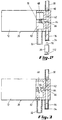
- valve 28 there is shown a partial cross-sectional view of valve 28.
- Conduit 30 is secured to inlet 60 of passageway 62.
- Outlet 64 of branch passageway 66 in fluid communication with passageway 62, is selectively closed by a seal member 68 disposed at the end of plunger 70.
- Plunger 70 is the operative element of a solenoid valve 72, which valve may be a latching valve that requires no current to operate except during a change of state of plunger 70 or it may be a monostable valve.
- Passageway 62 extends into a conduit 36, which may be a flexible conduit.
- Fill valve 34 (shown representatively) at the terminal end of conduit 36 prevents outflow and yet accommodates insertion of nozzle 78 of a syringe 38.
- Outlet 64 when not closed by seal member 68, evacuates liquid into an encircling chamber 82.
- Outlet 32 is in fluid communication with chamber 82 to permit flow of liquid from within the chamber through the outlet.
- valve 28 As depicted by arrow 84 in Figure 3, once flow of liquid enters valve 28 through conduit 30, it flows into passageway 62, branch passageway 66, through outlet 64 and into chamber 82 for discharge through outlet 32. The discharge will continue for as long as seal member 68 is retracted by plunger 70 as a result of actuation of solenoid 72. To halt further flow of fluid, an appropriate electrical signal is transmitted to solenoid 72 to extend plunger 70 and position seal member 68 adjacent outlet 64 to close the outlet.
- valve 34 there is illustrated a detailed partial cutaway view of valve 34.
- the valve includes a fitting 90 engaging the end of conduit 36.
- a cap 92 is attached to fitting 90 for the purpose of retaining a pair of flexible opposed rubber membranes or sealing elements 94,96 in place.
- These sealing elements may be in the shape of two semicircular, elastomeric, flexible planar elements, as depicted in Figure 4b.
- elements 94,96 When in position, elements 94,96 abut one another, as depicted in Figure 4c and form a seal at the junction.
- the mating of fitting 90 in cap 92 provides a seal adjacent the circular perimeter of abutting elements 94,96. Thereby, elements 94,96 of valve 34 preclude outflow through valve 34.
- FIG. 5 there is illustrated apparatus for initially drawing fluid into and through conduit 30 to valve 28.
- Nozzle 78 of syringe 38 is inserted through entryway 102 at the lower end of cap 92.
- the entryway may include an annular sealing element 104 for encircling nozzle 78 upon penetration of the nozzle to prevent leakage of the liquid therepast. Further, penetrable insertion of the nozzle forces the abutting edges of elements 94,96 upwardly and apart from one another (see also Figures 4a, 4b, and 4c) to bring inlet 106 of nozzle 78 into fluid communication with the interior of conduit 30 through chamber 108 and entryway 110 adjacent the end of the conduit 36.
- valve 28 Upon withdrawal of nozzle 78, elements 94,96 will resume their former abutting relationship and provide a seal to prevent outflow of liquid from valve 34 through entryway 102.
- liquid Upon actuation of valve 28 (see Figure 3) liquid will flow past seal member 68 into chamber 82 and be discharged through outlet 32. Hydrostatic pressure (head pressure) present in conduit 30 will ensure discharge of liquid whenever valve 28 is open.
- the conduit 30 may be also initially filled by opening valve 28 and by exerting for example manually a pressure upon the container so as to squeeze liquid soap in the conduit 30.
- no additional valve 34 has to be provided or, when an additional valve has been provided, for example a valve which can be opened manually, this latter valve may be used to provide an outlet for the air initially contained in the conduit 30 so that this conduit can be filled by squeezing the bag thus requiring no syringe or other suction device for creating a below atmospheric pressure in the conduit 30.
- Actuation of valve 28 may be through use of a manual switch actuated by a user. Alternatively, it may be through use of an active or passive for example infrared sensor sensing the presence, movement or temperature change of a user, a users hands, or other body part within a target volume.
- the target volume may be a volume commensurate with all or part of a wash basin or it may be a volume in proximity to outlet 32 or other element. If the sensor is a passive sensor, it will draw very little current. Sensors of the type useable herewith are described in any one of U.S. Patent Nos. 4,941,219, 5,086,526, 5,215,216, and 5,217,035 incorporated by reference.
- valve 72 By employing a latching solenoid valve 72, as described above, very little current consumption occurs since current is only drawn during a change of state of the valve. However, it may also be possible to use monostable valves, in particular monostable valves designed to have a small power consumption. Thereby, battery operation for both the sensor, preferably a passive sensor or a little power consuming active sensor, and the latching valve is feasible and practical since such a battery need not be replaced for an extended period of time.
- the actuation/deactuation of valve 28 may be performed automatically for a predetermined period or as a function of the proximity of a user.
- An important advantage of the present invention is that the dispenser does not require additional energy for withdrawing liquid from the container and even not to maintain the flow rate thereof substantially constant. Indeed, flow of liquid out of the container is achieved by the force of gravity acting thereon whilst the energy required to keep the flow rate constant is automatically obtained by placing the container in the dispenser whereby potential energy is stored in the springs as a result of the weight of the liquid.
- This advantage may thus be important for making it practical to use one or more batteries as power source in an automatic dispenser.
- a unit 40 intended to be representative of a sensor, such as a passive infrared sensor, for initiating and/or terminating outflow through outlet 32 by operation of valve 28, circuitry for actuating and deactuating valve 28, whether responsive to a sensor or other signal generating element and a power supply, such as a battery.
- a sensor such as a passive infrared sensor
Abstract
Description
- The present invention relates to dispensers for a personal hygiene liquid and, more particularly, to gravity fed liquid dispensers having a constant flow rate, comprising a container for the liquid, which liquid has a level situated at a first height, a liquid outlet situated at a second height lower than the first height, a conduit for allowing flow of liquid from said container to said liquid outlet in response to hydrostatic pressure of the liquid, and a valve for controlling the flow of liquid through said outlet.
- Gravity fed liquid dispensers suffer from a common problem of diminishing flow rate as a function of the lowering fluid level within the dispenser. One technique for solving this problem is set forth in EP-B-0 127 497. Herein, liquid soap is disposed within a flexible container. Outflow of the liquid soap is provided by a conduit defining an outlet and a valve controls flow through the conduit. The flow rate of the liquid soap through the outlet is maintained by applying pressure to the container. In particular, apparatus is provided for gradually increasing the pressure on the container as the container is gradually emptied. The apparatus includes a pressure plate and a spring acting through a specially designed lever mechanism to gradually increase the force exerted by the pressure plate upon the container.
- This known device is suitable for many applications but it incorporates certain drawbacks. To operate it, a flexible, collapsible container must be used to permit the pressure plate to decrease the volume in the container to expel the liquid soap. As the pressure upon the container increases, a risk of leakage through a seam or seal, such as the seal attendant the conduit extending from the container, is increased. Moreover, bursting of the container is also a possibility.
- An object of the present invention is therefore to provide an alternate mechanism for maintaining the flow rate of fluid through the outlet of the dispenser constant, which mechanism does not present the above-mentioned drawbacks of the known dispenser.
- To this end, the dispenser according to the invention is characterized in that said container is movably mounted in the dispenser and is supported by a weight responsive element for raising said container in proportion to depletion of the liquid from said container to maintain the hydrostatic pressure at said outlet essentially constant irrespective of the degree of fill of said container.
- In the dispenser according to the invention no additional pressure is to be exerted on the liquid but the hydrostatic pressure thereof is kept constant by adjusting the height of the container. This container may thus be a rigid container or for example a flexible bag.
- In an advantageous embodiment of the dispenser according to the invention said weight responsive element comprises at least one spring for supporting said container.
- In this embodiment, the spring constant of the spring or springs used to support the container can be determined in such a manner that the level of said personal hygiene liquid in the container is kept at a substantially constant height, resulting thus in a constant hydrostatic pressure.
- In a particular embodiment of the dispenser according to the invention, said conduit comprises a flexible tube having one end inserted into said container for siphoning the liquid.
- As mentioned already hereinabove, no external pressure is exerted onto the soap bag in the dispenser according to the present invention which considerably reduces the risk of leakage at the place of insertion of the flexible tube. Use can thus be made of prefilled soap bags which do not have to be provided with an outlet tube as disclosed in EP-B-0 127 497.
- Further particularities and advantages of the present invention will become apparent from the following description of some particular embodiments of the soap dispenser according to the invention. This description is only given by way of example and is not intended to limit the scope of the invention. The reference numerals relate to the annexed drawings wherein:
- Figure 1 is a representative perspective view of the present invention;
- Figure 2 illustrates a valve for controlling the flow rate and apparatus for initiating outflow from a filled container;
- Figure 3 illustrates the flow controlling valve in the open state;
- Figure 4a illustrates a valve in the closed state for accommodating initiation of flow of liquid from a container;
- Figure 4b illustrates two flexible elements of the valve shown in Figure 4a;
- Figure 4c illustrates the two flexible elements of the valve shown in Figures 4a and 4b in an abutting relationship; and
- Figure 5 illustrates the valve shown in Figure 4a in the open state and related apparatus for initiating flow of liquid from the container.
- Referring to Figure 1, there is illustrated a dispenser 10 for dispensing a personal hygiene liquid, such as liquid soap, shampoo, hair conditioner, etc. Other liquids for various purposes can also be dispensed through use of dispenser 10. For discussion purposes, it will be assumed that the liquid to be dispensed is liquid soap for personal hygiene purposes.
- Dispenser 10 includes a
container 12 essentially filled with liquid soap and disposed upon ashelf 14, which may be any type of support or supporting element. The shelf is vertically slidably mounted upon a pair of stanchions orposts compressible coil springs posts shelf 14 at a height commensurate with the weight ofcontainer 12 and the spring force exerted by the springs.Posts pedestal 24. Aplatform 26 depending frompedestal 24 byplate 25 supports avalve 28 for controlling fluid flow throughconduit 30 and fluid discharge throughoutlet 32. To initiate flow from a filledcontainer 12, aconduit fill valve 34, mounted uponplatform 26, may be employed. The fill valve is in fluid communication withconduit 30 via afurther conduit 36. Asyringe 38, or other device interconnecting withvalve 34 for the purpose of drawing fluid throughconduit 30 intovalve 28, may be employed. -
Container 12 may be a rigid container having an outlet for interconnection withconduit 30. Alternatively, and preferably,container 12 is a closed flexible container without an outlet and filled with the liquid to be dispensed. Access to the liquid within the container may be accomplished by ahollow needle 50 mechanically attached to and in fluid communication withend 52 ofconduit 30. Ifcontainer 12 is of the type described in the co-pending European patent application, wherein the priority of US patent application Serial No. 08/518,425, filed December 27, 1995, is claimed and a copy of which is furnished to the European Patent Office at the same time as the present patent application, and as shown in Figure 1,needle 50 is brought into penetrable engagement with awall 54 of the container. The characteristics of the wall of the container will form a seal about the circumference of the needle to prevent leakage about the needle. Thus, the liquid contents ofcontainer 12 may be discharged throughneedle 50 intoconduit 30 in response to opening ofvalve 28 and liquid outflow throughoutlet 32. - The use of such a filled flexible container permits replacement of the container by simply withdrawing
needle 50 from the exhausted container and inserting the needle through the wall of a replacement container. This procedure essentially prevents spillage of the liquid during container replacement and is easily performable by maintenance personnel. - Once
conduit 30 is filled, and whenvalve 28 is open, the flow rate of discharged liquid is a function of two factors. First, the hydrostatic pressure or head pressure atoutlet 32 is a function of the difference in height between first height H0 of the level of the liquid withincontainer 12 and second height H1 ofoutlet 32. As the liquid within the container is depleted, the level of the liquid will drop to a height below height H0. With such drop in level and commensurate reduction in height difference, the head pressure will be reduced with a commensurate effect upon the flow rate. To maintain the flow rate constant, it is necessary to maintain the level of the liquid essentially constant at height H0 despite depletion of liquid withincontainer 12. - As the quantity of liquid within
container 12 is reduced, the weight of the container is commensurately reduced. This change in weight provides a reduced compressive force upon supportingsprings shelf 14 resulting in extension of the springs commensurate with the reduced weight of the container. Upon extension of the springs,shelf 14 will be raised and the level of the liquid withincontainer 12 will be raised. By matchingsprings container 12 to cause the container to be raised a height equivalent to the lowered level of the liquid within the container from a full to an empty container, the liquid level within the container is retained essentially at height H0 during depletion of the liquid. Thereby, the hydrostatic force or head pressure causing flow of liquid throughconduit 30 and discharged throughoutlet 32 will remain essentially constant irrespective of the extent of depletion of liquid from withincontainer 12. - Instead of being supported by
springs - Referring to Figure 2, there is shown a partial cross-sectional view of
valve 28.Conduit 30 is secured to inlet 60 ofpassageway 62.Outlet 64 ofbranch passageway 66, in fluid communication withpassageway 62, is selectively closed by aseal member 68 disposed at the end of plunger 70. Plunger 70 is the operative element of a solenoid valve 72, which valve may be a latching valve that requires no current to operate except during a change of state of plunger 70 or it may be a monostable valve.Passageway 62 extends into aconduit 36, which may be a flexible conduit. Fill valve 34 (shown representatively) at the terminal end ofconduit 36 prevents outflow and yet accommodates insertion ofnozzle 78 of asyringe 38.Outlet 64, when not closed byseal member 68, evacuates liquid into an encirclingchamber 82.Outlet 32 is in fluid communication withchamber 82 to permit flow of liquid from within the chamber through the outlet. - As depicted by
arrow 84 in Figure 3, once flow of liquid entersvalve 28 throughconduit 30, it flows intopassageway 62,branch passageway 66, throughoutlet 64 and intochamber 82 for discharge throughoutlet 32. The discharge will continue for as long asseal member 68 is retracted by plunger 70 as a result of actuation of solenoid 72. To halt further flow of fluid, an appropriate electrical signal is transmitted to solenoid 72 to extend plunger 70 andposition seal member 68adjacent outlet 64 to close the outlet. - Referring to Figure 4a, there is illustrated a detailed partial cutaway view of
valve 34. The valve includes a fitting 90 engaging the end ofconduit 36. Acap 92 is attached to fitting 90 for the purpose of retaining a pair of flexible opposed rubber membranes or sealingelements elements cap 92 provides a seal adjacent the circular perimeter of abuttingelements elements valve 34 preclude outflow throughvalve 34. - Referring to Figure 5, there is illustrated apparatus for initially drawing fluid into and through
conduit 30 tovalve 28.Nozzle 78 ofsyringe 38 is inserted throughentryway 102 at the lower end ofcap 92. The entryway may include anannular sealing element 104 for encirclingnozzle 78 upon penetration of the nozzle to prevent leakage of the liquid therepast. Further, penetrable insertion of the nozzle forces the abutting edges ofelements inlet 106 ofnozzle 78 into fluid communication with the interior ofconduit 30 throughchamber 108 andentryway 110 adjacent the end of theconduit 36. Upon withdrawal of plunger 112 (see Figure 1) ofsyringe 38, a below ambient pressure environment is formed withinchamber 108 andentryway 110. The resulting low pressure is translated throughconduit 36 intoconduit 30. The atmospheric pressure acting uponcontainer 12 and being greater than the reduced pressure withinconduit 30 will compress the container to force liquid throughneedle 50 into the conduit. Such flow will quickly fill the conduit,passageway 62,branch passageway 66, andconduit 36. (See Figures 2 and 3). The resulting liquid flow fromconduit 36 intochamber 108 may flowintermediate elements adjacent nozzle 78. However, seal 104 aboutnozzle 78 will preclude further outflow of the liquid. Upon withdrawal ofnozzle 78,elements valve 34 throughentryway 102. Upon actuation of valve 28 (see Figure 3) liquid will flowpast seal member 68 intochamber 82 and be discharged throughoutlet 32. Hydrostatic pressure (head pressure) present inconduit 30 will ensure discharge of liquid whenevervalve 28 is open. - In case use is made of a flexible container or bag for housing the liquid soap, the
conduit 30 may be also initially filled by openingvalve 28 and by exerting for example manually a pressure upon the container so as to squeeze liquid soap in theconduit 30. In this case, noadditional valve 34 has to be provided or, when an additional valve has been provided, for example a valve which can be opened manually, this latter valve may be used to provide an outlet for the air initially contained in theconduit 30 so that this conduit can be filled by squeezing the bag thus requiring no syringe or other suction device for creating a below atmospheric pressure in theconduit 30. - Actuation of
valve 28 may be through use of a manual switch actuated by a user. Alternatively, it may be through use of an active or passive for example infrared sensor sensing the presence, movement or temperature change of a user, a users hands, or other body part within a target volume. The target volume may be a volume commensurate with all or part of a wash basin or it may be a volume in proximity tooutlet 32 or other element. If the sensor is a passive sensor, it will draw very little current. Sensors of the type useable herewith are described in any one of U.S. Patent Nos. 4,941,219, 5,086,526, 5,215,216, and 5,217,035 incorporated by reference. By employing a latching solenoid valve 72, as described above, very little current consumption occurs since current is only drawn during a change of state of the valve. However, it may also be possible to use monostable valves, in particular monostable valves designed to have a small power consumption. Thereby, battery operation for both the sensor, preferably a passive sensor or a little power consuming active sensor, and the latching valve is feasible and practical since such a battery need not be replaced for an extended period of time. The actuation/deactuation ofvalve 28 may be performed automatically for a predetermined period or as a function of the proximity of a user. - An important advantage of the present invention is that the dispenser does not require additional energy for withdrawing liquid from the container and even not to maintain the flow rate thereof substantially constant. Indeed, flow of liquid out of the container is achieved by the force of gravity acting thereon whilst the energy required to keep the flow rate constant is automatically obtained by placing the container in the dispenser whereby potential energy is stored in the springs as a result of the weight of the liquid. This advantage may thus be important for making it practical to use one or more batteries as power source in an automatic dispenser.
- Referring to Figure 1, there is illustrated a
unit 40 intended to be representative of a sensor, such as a passive infrared sensor, for initiating and/or terminating outflow throughoutlet 32 by operation ofvalve 28, circuitry for actuating anddeactuating valve 28, whether responsive to a sensor or other signal generating element and a power supply, such as a battery. - While the invention has been described with reference to several particular embodiments thereof, those skilled in the art will be able to make the various modifications to the described embodiments of the invention without departing from the true spirit and scope of the invention. It is intended that all combinations of elements and steps which perform substantially the same function in substantially the same way to achieve the same result are within the scope of the invention.
Claims (10)
- A dispenser for a personal hygiene liquid comprising a container for the liquid, which liquid has a level situated at a first height, a liquid outlet situated at a second height lower than the first height, a conduit for allowing flow of liquid from said container to said liquid outlet in response to hydrostatic pressure of the liquid, and a valve for controlling the flow of liquid through said outlet, characterized in that said container is movably mounted in the dispenser and is supported by a weight responsive element for raising said container in proportion to depletion of the liquid from said container to maintain the hydrostatic pressure at said outlet essentially constant irrespective of the degree of fill of said container.
- A dispenser according to claim 1, characterized in that said weight responsive element is formed by resilient means adapted to increase the height of said container to keep the level of the liquid at a substantially constant height.
- A dispenser according to claim 1 or 2, characterized in that said weight responsive element comprises at least one spring for supporting said container.
- A dispenser according to any one of the claims 1 to 3, characterized in that said spring is a coil spring.
- A dispenser according to any one of the claims 1 to 4, characterized in that said container is a disposable flexible bag.
- A dispenser according to any one of the claims 1 to 5, characterized in that said conduit comprises a flexible tube having one end inserted into said container for siphoning the liquid.
- A dispenser according to any one of the claims 1 to 6, characterized in that said conduit includes a hollow needle attached to said conduit and said container includes a wall for penetrable engagement by said needle to form a seal about said needle upon penetrable engagement of said needle with said wall.
- A dispenser according to any one of the claims 1 to 7, characterized in that it includes a further valve in fluid communication with said conduit for initially filling said conduit with the liquid by subjecting said conduit to a below ambient pressure to draw the liquid into said conduit from said container and/or by pressing the liquid into said conduit by exerting a pressure onto the liquid in said container.
- A dispenser according to claim 8, characterized in that it includes a syringe for engaging said further valve to create the below ambient pressure within said conduit.
- A dispenser according to any one of the claims 1 to 9, characterized in that it comprises means for automatically controlling the operation of said valve.
Applications Claiming Priority (2)
| Application Number | Priority Date | Filing Date | Title |
|---|---|---|---|
| US578080 | 1995-12-27 | ||
| US08/578,080 US5782382A (en) | 1995-12-27 | 1995-12-27 | Dispenser for personal hygiene liquids |
Publications (2)
| Publication Number | Publication Date |
|---|---|
| EP0781521A1 true EP0781521A1 (en) | 1997-07-02 |
| EP0781521B1 EP0781521B1 (en) | 2002-07-03 |
Family
ID=24311357
Family Applications (1)
| Application Number | Title | Priority Date | Filing Date |
|---|---|---|---|
| EP96203617A Expired - Lifetime EP0781521B1 (en) | 1995-12-27 | 1996-12-27 | Dispenser for a personal hygiene liquid |
Country Status (4)
| Country | Link |
|---|---|
| US (1) | US5782382A (en) |
| EP (1) | EP0781521B1 (en) |
| AT (1) | ATE219906T1 (en) |
| DE (1) | DE69622136D1 (en) |
Cited By (3)
| Publication number | Priority date | Publication date | Assignee | Title |
|---|---|---|---|---|
| WO2007085782A1 (en) * | 2006-01-30 | 2007-08-02 | Peter Sage-Passant | Dispensing device |
| WO2011141357A1 (en) | 2010-05-12 | 2011-11-17 | Tecan Trading Ag | Dispenser and process for releasing flowable materials |
| WO2011156613A1 (en) * | 2010-06-10 | 2011-12-15 | Denis Keyes | Fluid dispensing apparatus |
Families Citing this family (27)
| Publication number | Priority date | Publication date | Assignee | Title |
|---|---|---|---|---|
| US6527758B2 (en) * | 2001-06-11 | 2003-03-04 | Kam Ko | Vial docking station for sliding reconstitution with diluent container |
| US20070000941A1 (en) * | 2005-07-01 | 2007-01-04 | Hadden David M | Motion-activated soap dispenser |
| US11185604B2 (en) | 2006-03-31 | 2021-11-30 | Deep Science Llc | Methods and systems for monitoring sterilization status |
| US20070231192A1 (en) * | 2006-03-31 | 2007-10-04 | Searete Llc, A Limited Liability Corporation Of The State Of Delaware | Sterilization methods and systems |
| US8758679B2 (en) * | 2006-03-31 | 2014-06-24 | The Invention Science Fund I, Llc | Surveying sterilizer methods and systems |
| US8932535B2 (en) | 2006-03-31 | 2015-01-13 | The Invention Science Fund I, Llc | Surveying sterilizer methods and systems |
| US8114342B2 (en) * | 2006-03-31 | 2012-02-14 | The Invention Science Fund I, Llc | Methods and systems for monitoring sterilization status |
| US20070254015A1 (en) * | 2006-04-28 | 2007-11-01 | Searete Llc, A Limited Liability Corporation Of The State Of Delaware | Sanitizing surfaces |
| WO2009039290A2 (en) | 2007-09-20 | 2009-03-26 | Bradley Fixtures Corporation | Lavatory system |
| US8360278B2 (en) | 2007-12-05 | 2013-01-29 | Freeze King | Pressure vessel, system and/or method for dispensing a comestible mixture |
| EP2218514B1 (en) * | 2009-02-09 | 2017-04-26 | J. Wagner AG | Coating powder supply device |
| MX366199B (en) | 2009-10-07 | 2019-06-25 | Bradley Fixtures Corp | Lavatory system with hand dryer. |
| US9170148B2 (en) | 2011-04-18 | 2015-10-27 | Bradley Fixtures Corporation | Soap dispenser having fluid level sensor |
| US9267736B2 (en) | 2011-04-18 | 2016-02-23 | Bradley Fixtures Corporation | Hand dryer with point of ingress dependent air delay and filter sensor |
| EP2828440B1 (en) | 2012-03-21 | 2018-06-27 | Bradley Fixtures Corporation | Basin and hand drying system |
| US10100501B2 (en) | 2012-08-24 | 2018-10-16 | Bradley Fixtures Corporation | Multi-purpose hand washing station |
| US9504370B2 (en) * | 2012-12-07 | 2016-11-29 | Ecolab Usa Inc. | Magnetic low product indicator |
| US9764937B2 (en) * | 2013-05-15 | 2017-09-19 | Ecolab Usa Inc. | Mass based low product indicator |
| GB2519299B (en) * | 2013-10-15 | 2021-01-20 | Mechline Developments Ltd | Dispensing device |
| CA2963062A1 (en) * | 2014-10-02 | 2016-04-07 | Mondiale Technologies Limited | Gravity infusion iv bag |
| US11027960B2 (en) | 2015-08-13 | 2021-06-08 | David G. Kraenzle | Apparatus, systems, and methods relating to transfer of liquids to/from containers and/or storage of liquids in containers |
| US10005654B2 (en) * | 2015-08-13 | 2018-06-26 | David G. Kraenzle | Apparatus, systems, and methods relating to transfer of fluids to/from containers and/or storage/transport of fluids in containers |
| US10785993B2 (en) * | 2016-05-31 | 2020-09-29 | Taylor Commercial Foodservice, Llc | Valve assembly for a food product container of a food product dispensing machine |
| US10041236B2 (en) | 2016-06-08 | 2018-08-07 | Bradley Corporation | Multi-function fixture for a lavatory system |
| US11015329B2 (en) | 2016-06-08 | 2021-05-25 | Bradley Corporation | Lavatory drain system |
| WO2018156974A1 (en) * | 2017-02-24 | 2018-08-30 | GreenStract, LLC | Gravimetric apparatus for transferring fluids |
| CN109052727B (en) * | 2018-09-11 | 2021-11-23 | 上海人民企业集团水泵有限公司 | Municipal administration sewage treatment plant |
Citations (5)
| Publication number | Priority date | Publication date | Assignee | Title |
|---|---|---|---|---|
| FR575738A (en) * | 1923-01-13 | 1924-08-05 | Apparatus for dispensing liquid substances in predetermined quantities | |
| US2074554A (en) * | 1933-08-19 | 1937-03-23 | William P Myron | Liquid dispenser |
| GB623087A (en) * | 1946-02-22 | 1949-05-12 | Horton Mfg Company Ltd | Improvements relating to apparatus for dispensing liquid soap |
| EP0127497B1 (en) * | 1983-04-26 | 1987-06-24 | Calgon Corporation | Fluid dispenser |
| FR2701646A1 (en) * | 1993-02-19 | 1994-08-26 | Provendi Sa | Electromagnetically controlled dispenser for dispensing liquid or pasty products |
Family Cites Families (34)
| Publication number | Priority date | Publication date | Assignee | Title |
|---|---|---|---|---|
| US2771878A (en) * | 1952-08-27 | 1956-11-27 | American Optical Corp | Intravenous infusion system |
| US2986142A (en) * | 1954-02-08 | 1961-05-30 | American Hospital Supply Corp | Liquid packaging and dispensing means |
| US3033248A (en) * | 1960-06-30 | 1962-05-08 | Dohrmann Sales Company | Proximity electronic water station |
| US3273752A (en) * | 1965-02-11 | 1966-09-20 | Geza E Horeczky | Photo-electric controlled dispenser |
| GB1145803A (en) * | 1966-09-16 | 1969-03-19 | Distillers Co Carbon Dioxide | Liquid dispensing apparatus |
| US3434628A (en) * | 1967-01-23 | 1969-03-25 | Bernard A Ceraldi | Automatic soap dispenser |
| US3452361A (en) * | 1967-12-22 | 1969-06-24 | Leeds & Northrup Co | Ink supply for capillary pen |
| US4008831A (en) * | 1972-11-20 | 1977-02-22 | Jacques Vidilles | Safety reservoir for hydrocarbons and dangerous liquids |
| US4008830A (en) * | 1973-08-10 | 1977-02-22 | Philip Meshberg | Liquid dispenser using a non vented pump and a collapsible plastic bag |
| US3843020A (en) * | 1973-08-16 | 1974-10-22 | W Bardeau | Automatic liquid dispensing apparatus |
| US3991912A (en) * | 1975-01-23 | 1976-11-16 | Ricardo Hurtado Soto | Flexible package with counter-pressure dispenser |
| US4261356A (en) * | 1978-10-23 | 1981-04-14 | Baxter Travenol Laboratories, Inc. | Method and apparatus for controlling the dispensing of fluid |
| US4375864A (en) * | 1980-07-21 | 1983-03-08 | Scholle Corporation | Container for holding and dispensing fluid |
| US4484697A (en) * | 1980-08-27 | 1984-11-27 | Shasta Beverages, Inc. | Method and apparatus for dispensing liquid |
| US4455139A (en) * | 1982-03-23 | 1984-06-19 | Whitman Medical Corporation | Intravenous liquid leveling device |
| US4645094A (en) * | 1983-04-26 | 1987-02-24 | Calgon Corporation | Photo-electric controlled dispenser |
| US4527716A (en) * | 1983-05-13 | 1985-07-09 | Cargill, Incorporated | Apparatus for dispensing material from a bag |
| SU1224592A1 (en) * | 1984-10-04 | 1986-04-15 | Всесоюзный Научно-Исследовательский Биотехнический Институт | Arrangement for liquid or gas metering |
| US4863066A (en) * | 1986-06-02 | 1989-09-05 | Technicon Instruments Corporation | System for dispensing precisely metered quantities of a fluid and method of utilizing the system |
| US4998850A (en) * | 1988-11-03 | 1991-03-12 | Park Corporation | Gel dispensing apparatus and method |
| US4938421A (en) * | 1988-12-23 | 1990-07-03 | Shop-Vac Corporation | Cleaning liquid mixer for a water line, particularly for a surface cleaner |
| US4946072A (en) * | 1989-02-16 | 1990-08-07 | Johnson & Johnson Medical, Inc. | Container for surgical soap dispenser |
| US5004158A (en) * | 1989-08-21 | 1991-04-02 | Stephen Halem | Fluid dispensing and mixing device |
| US5086526A (en) * | 1989-10-10 | 1992-02-11 | International Sanitary Ware Manufacturin Cy, S.A. | Body heat responsive control apparatus |
| US4941219A (en) * | 1989-10-10 | 1990-07-17 | International Sanitary Ware Manufacturing Cy, S.A. | Body heat responsive valve control apparatus |
| US4956883A (en) * | 1989-10-30 | 1990-09-18 | Dale Lane | Shower fixture |
| US5188261A (en) * | 1990-01-12 | 1993-02-23 | Inotec Corporation | Collapsible drink dispenser |
| US5178300A (en) * | 1990-06-06 | 1993-01-12 | Shlomo Haviv | Fluid dispensing unit with one-way valve outflow |
| DE69007112T2 (en) * | 1990-07-05 | 1994-09-08 | Hormec Technic Sa | DISPENSER FOR THE DISPENSED DISPENSING OF LIQUIDS, IN PARTICULAR FOR THE ADHESIVE JOINTING OF ELEMENTS. |
| US5195655A (en) * | 1991-05-24 | 1993-03-23 | Motorola, Inc. | Integrated fluid dispense apparatus to reduce contamination |
| US5215216A (en) * | 1991-09-25 | 1993-06-01 | International Sanitary Ware Manufacturing | Water flow responsive soap dispenser |
| US5251787A (en) * | 1992-03-09 | 1993-10-12 | Simson Anton K | Pressurized container dispenser |
| US5217035A (en) * | 1992-06-09 | 1993-06-08 | International Sanitary Ware Mfg. Cy, S.A. | System for automatic control of public washroom fixtures |
| US5566732A (en) * | 1995-06-20 | 1996-10-22 | Exel Nelson Engineering Llc | Beverage dispenser with a reader for size indica on a serving container |
-
1995
- 1995-12-27 US US08/578,080 patent/US5782382A/en not_active Expired - Fee Related
-
1996
- 1996-12-27 AT AT96203617T patent/ATE219906T1/en not_active IP Right Cessation
- 1996-12-27 EP EP96203617A patent/EP0781521B1/en not_active Expired - Lifetime
- 1996-12-27 DE DE69622136T patent/DE69622136D1/en not_active Expired - Lifetime
Patent Citations (5)
| Publication number | Priority date | Publication date | Assignee | Title |
|---|---|---|---|---|
| FR575738A (en) * | 1923-01-13 | 1924-08-05 | Apparatus for dispensing liquid substances in predetermined quantities | |
| US2074554A (en) * | 1933-08-19 | 1937-03-23 | William P Myron | Liquid dispenser |
| GB623087A (en) * | 1946-02-22 | 1949-05-12 | Horton Mfg Company Ltd | Improvements relating to apparatus for dispensing liquid soap |
| EP0127497B1 (en) * | 1983-04-26 | 1987-06-24 | Calgon Corporation | Fluid dispenser |
| FR2701646A1 (en) * | 1993-02-19 | 1994-08-26 | Provendi Sa | Electromagnetically controlled dispenser for dispensing liquid or pasty products |
Cited By (5)
| Publication number | Priority date | Publication date | Assignee | Title |
|---|---|---|---|---|
| US8444015B2 (en) | 2005-08-09 | 2013-05-21 | Denis E. Keyes | Fluid dispensing apparatus |
| WO2007085782A1 (en) * | 2006-01-30 | 2007-08-02 | Peter Sage-Passant | Dispensing device |
| GB2434573B (en) * | 2006-01-30 | 2009-08-12 | Peter Sage-Passant | Dispensing device |
| WO2011141357A1 (en) | 2010-05-12 | 2011-11-17 | Tecan Trading Ag | Dispenser and process for releasing flowable materials |
| WO2011156613A1 (en) * | 2010-06-10 | 2011-12-15 | Denis Keyes | Fluid dispensing apparatus |
Also Published As
| Publication number | Publication date |
|---|---|
| US5782382A (en) | 1998-07-21 |
| DE69622136D1 (en) | 2002-08-08 |
| ATE219906T1 (en) | 2002-07-15 |
| EP0781521B1 (en) | 2002-07-03 |
Similar Documents
| Publication | Publication Date | Title |
|---|---|---|
| EP0781521B1 (en) | Dispenser for a personal hygiene liquid | |
| JP3272722B2 (en) | Apparatus for dispensing fluid droplets | |
| EP0195778B1 (en) | Liquid container dispensing cap structure | |
| US2665825A (en) | Pressure-operable liquid dispensing apparatus | |
| US4018363A (en) | Soap dispenser | |
| US4489857A (en) | Liquid dispenser | |
| EP0043846B1 (en) | Device for dispensing amounts of a liquid and base member for such a dispensing device | |
| TW503094B (en) | Gas-driven liquid dispenser employing separate pressurized-gas source | |
| US5215216A (en) | Water flow responsive soap dispenser | |
| US4646945A (en) | Vented discharge assembly for liquid soap dispenser | |
| US4957218A (en) | Foamer and method | |
| US4030634A (en) | Bottled water transfer device | |
| US5226566A (en) | Modular counter mounted fluid dispensing apparatus | |
| JPS6335519B2 (en) | ||
| FI69517C (en) | ANORDINATION FOR RANSONERING AV VISKOSISKA KONCENTRATER MED FOERAENDERLIG VISKOSITET I EXAKTA MAENGDER MED VARIERANDE VOLUMER | |
| AU712354B2 (en) | Liquid container with resealable outlet | |
| EP1267692B1 (en) | Liquid dispenser | |
| CZ285182B6 (en) | Method of producing foam doses from liquid soap and apparatus for making the same | |
| JPH0299022A (en) | Fluid push-up type dispenser | |
| US4393982A (en) | Metered dispensing of liquids | |
| JPH08507278A (en) | Ultra-low speed fluid dispenser from container | |
| US5850947A (en) | Invertible and multi-directional fluid delivery device | |
| US5725129A (en) | Dual-container foam dispenser | |
| GB2037255A (en) | Metered dispensing of liquids | |
| CA1215657A (en) | Pressure vessel for receiving liquids to be conveyed |
Legal Events
| Date | Code | Title | Description |
|---|---|---|---|
| PUAI | Public reference made under article 153(3) epc to a published international application that has entered the european phase |
Free format text: ORIGINAL CODE: 0009012 |
|
| AK | Designated contracting states |
Kind code of ref document: A1 Designated state(s): AT BE CH DE DK ES FR GB IT LI LU NL SE |
|
| 17P | Request for examination filed |
Effective date: 19971218 |
|
| 17Q | First examination report despatched |
Effective date: 19990826 |
|
| GRAG | Despatch of communication of intention to grant |
Free format text: ORIGINAL CODE: EPIDOS AGRA |
|
| GRAG | Despatch of communication of intention to grant |
Free format text: ORIGINAL CODE: EPIDOS AGRA |
|
| GRAG | Despatch of communication of intention to grant |
Free format text: ORIGINAL CODE: EPIDOS AGRA |
|
| GRAH | Despatch of communication of intention to grant a patent |
Free format text: ORIGINAL CODE: EPIDOS IGRA |
|
| GRAH | Despatch of communication of intention to grant a patent |
Free format text: ORIGINAL CODE: EPIDOS IGRA |
|
| GRAA | (expected) grant |
Free format text: ORIGINAL CODE: 0009210 |
|
| AK | Designated contracting states |
Kind code of ref document: B1 Designated state(s): AT BE CH DE DK ES FR GB IT LI LU NL SE |
|
| PG25 | Lapsed in a contracting state [announced via postgrant information from national office to epo] |
Ref country code: NL Free format text: LAPSE BECAUSE OF FAILURE TO SUBMIT A TRANSLATION OF THE DESCRIPTION OR TO PAY THE FEE WITHIN THE PRESCRIBED TIME-LIMIT Effective date: 20020703 Ref country code: LI Free format text: LAPSE BECAUSE OF FAILURE TO SUBMIT A TRANSLATION OF THE DESCRIPTION OR TO PAY THE FEE WITHIN THE PRESCRIBED TIME-LIMIT Effective date: 20020703 Ref country code: IT Free format text: LAPSE BECAUSE OF FAILURE TO SUBMIT A TRANSLATION OF THE DESCRIPTION OR TO PAY THE FEE WITHIN THE PRE;WARNING: LAPSES OF ITALIAN PATENTS WITH EFFECTIVE DATE BEFORE 2007 MAY HAVE OCCURRED AT ANY TIME BEFORE 2007. THE CORRECT EFFECTIVE DATE MAY BE DIFFERENT FROM THE ONE RECORDED.SCRIBED TIME-LIMIT Effective date: 20020703 Ref country code: FR Free format text: LAPSE BECAUSE OF FAILURE TO SUBMIT A TRANSLATION OF THE DESCRIPTION OR TO PAY THE FEE WITHIN THE PRESCRIBED TIME-LIMIT Effective date: 20020703 Ref country code: CH Free format text: LAPSE BECAUSE OF FAILURE TO SUBMIT A TRANSLATION OF THE DESCRIPTION OR TO PAY THE FEE WITHIN THE PRESCRIBED TIME-LIMIT Effective date: 20020703 Ref country code: BE Free format text: LAPSE BECAUSE OF FAILURE TO SUBMIT A TRANSLATION OF THE DESCRIPTION OR TO PAY THE FEE WITHIN THE PRESCRIBED TIME-LIMIT Effective date: 20020703 Ref country code: AT Free format text: LAPSE BECAUSE OF FAILURE TO SUBMIT A TRANSLATION OF THE DESCRIPTION OR TO PAY THE FEE WITHIN THE PRESCRIBED TIME-LIMIT Effective date: 20020703 |
|
| REF | Corresponds to: |
Ref document number: 219906 Country of ref document: AT Date of ref document: 20020715 Kind code of ref document: T |
|
| REG | Reference to a national code |
Ref country code: CH Ref legal event code: EP |
|
| REF | Corresponds to: |
Ref document number: 69622136 Country of ref document: DE Date of ref document: 20020808 |
|
| PG25 | Lapsed in a contracting state [announced via postgrant information from national office to epo] |
Ref country code: SE Free format text: LAPSE BECAUSE OF FAILURE TO SUBMIT A TRANSLATION OF THE DESCRIPTION OR TO PAY THE FEE WITHIN THE PRESCRIBED TIME-LIMIT Effective date: 20021003 Ref country code: DK Free format text: LAPSE BECAUSE OF FAILURE TO SUBMIT A TRANSLATION OF THE DESCRIPTION OR TO PAY THE FEE WITHIN THE PRESCRIBED TIME-LIMIT Effective date: 20021003 |
|
| PG25 | Lapsed in a contracting state [announced via postgrant information from national office to epo] |
Ref country code: DE Free format text: LAPSE BECAUSE OF FAILURE TO SUBMIT A TRANSLATION OF THE DESCRIPTION OR TO PAY THE FEE WITHIN THE PRESCRIBED TIME-LIMIT Effective date: 20021005 |
|
| NLV1 | Nl: lapsed or annulled due to failure to fulfill the requirements of art. 29p and 29m of the patents act | ||
| PG25 | Lapsed in a contracting state [announced via postgrant information from national office to epo] |
Ref country code: LU Free format text: LAPSE BECAUSE OF NON-PAYMENT OF DUE FEES Effective date: 20021227 Ref country code: GB Free format text: LAPSE BECAUSE OF NON-PAYMENT OF DUE FEES Effective date: 20021227 |
|
| REG | Reference to a national code |
Ref country code: CH Ref legal event code: PL |
|
| PG25 | Lapsed in a contracting state [announced via postgrant information from national office to epo] |
Ref country code: ES Free format text: LAPSE BECAUSE OF FAILURE TO SUBMIT A TRANSLATION OF THE DESCRIPTION OR TO PAY THE FEE WITHIN THE PRESCRIBED TIME-LIMIT Effective date: 20030130 |
|
| EN | Fr: translation not filed | ||
| PLBE | No opposition filed within time limit |
Free format text: ORIGINAL CODE: 0009261 |
|
| STAA | Information on the status of an ep patent application or granted ep patent |
Free format text: STATUS: NO OPPOSITION FILED WITHIN TIME LIMIT |
|
| 26N | No opposition filed |
Effective date: 20030404 |
|
| GBPC | Gb: european patent ceased through non-payment of renewal fee |
Effective date: 20021227 |