EP0781246B1 - Refuse container and dolly having foot activated release mechanism - Google Patents
Refuse container and dolly having foot activated release mechanism Download PDFInfo
- Publication number
- EP0781246B1 EP0781246B1 EP96924377A EP96924377A EP0781246B1 EP 0781246 B1 EP0781246 B1 EP 0781246B1 EP 96924377 A EP96924377 A EP 96924377A EP 96924377 A EP96924377 A EP 96924377A EP 0781246 B1 EP0781246 B1 EP 0781246B1
- Authority
- EP
- European Patent Office
- Prior art keywords
- dolly
- refuse container
- container
- container according
- support surface
- Prior art date
- Legal status (The legal status is an assumption and is not a legal conclusion. Google has not performed a legal analysis and makes no representation as to the accuracy of the status listed.)
- Expired - Lifetime
Links
- 230000007246 mechanism Effects 0.000 title description 7
- 230000033001 locomotion Effects 0.000 claims description 17
- 230000002093 peripheral effect Effects 0.000 claims description 6
- 230000000977 initiatory effect Effects 0.000 claims 1
- 230000000712 assembly Effects 0.000 description 8
- 238000000429 assembly Methods 0.000 description 8
- 230000001419 dependent effect Effects 0.000 description 7
- 238000000034 method Methods 0.000 description 7
- 238000000926 separation method Methods 0.000 description 6
- 230000008901 benefit Effects 0.000 description 4
- 230000014759 maintenance of location Effects 0.000 description 4
- 230000007812 deficiency Effects 0.000 description 3
- 230000001154 acute effect Effects 0.000 description 2
- 230000000295 complement effect Effects 0.000 description 2
- 238000010276 construction Methods 0.000 description 2
- 229920003023 plastic Polymers 0.000 description 2
- 239000004033 plastic Substances 0.000 description 2
- 208000004067 Flatfoot Diseases 0.000 description 1
- 239000004698 Polyethylene Substances 0.000 description 1
- 208000027418 Wounds and injury Diseases 0.000 description 1
- 238000005452 bending Methods 0.000 description 1
- 230000015572 biosynthetic process Effects 0.000 description 1
- 230000001010 compromised effect Effects 0.000 description 1
- 239000000356 contaminant Substances 0.000 description 1
- 230000002079 cooperative effect Effects 0.000 description 1
- 230000006378 damage Effects 0.000 description 1
- 230000007423 decrease Effects 0.000 description 1
- 230000002950 deficient Effects 0.000 description 1
- 230000000994 depressogenic effect Effects 0.000 description 1
- 230000002708 enhancing effect Effects 0.000 description 1
- 229920002457 flexible plastic Polymers 0.000 description 1
- 230000010006 flight Effects 0.000 description 1
- 230000006872 improvement Effects 0.000 description 1
- 238000002347 injection Methods 0.000 description 1
- 239000007924 injection Substances 0.000 description 1
- 208000014674 injury Diseases 0.000 description 1
- 238000004519 manufacturing process Methods 0.000 description 1
- 230000013011 mating Effects 0.000 description 1
- 238000000465 moulding Methods 0.000 description 1
- 238000010137 moulding (plastic) Methods 0.000 description 1
- OCDRLZFZBHZTKQ-NMUBGGKPSA-N onetine Chemical compound C[C@@H](O)[C@@]1(O)C[C@@H](C)[C@@](C)(O)C(=O)OC\C2=C\CN(C)CC[C@@H](OC1=O)C2=O OCDRLZFZBHZTKQ-NMUBGGKPSA-N 0.000 description 1
- -1 polyethylene Polymers 0.000 description 1
- 229920000573 polyethylene Polymers 0.000 description 1
- 230000008569 process Effects 0.000 description 1
- 230000000135 prohibitive effect Effects 0.000 description 1
- 238000009877 rendering Methods 0.000 description 1
- 230000000630 rising effect Effects 0.000 description 1
- 238000004513 sizing Methods 0.000 description 1
- 238000003860 storage Methods 0.000 description 1
Images





Classifications
-
- B—PERFORMING OPERATIONS; TRANSPORTING
- B65—CONVEYING; PACKING; STORING; HANDLING THIN OR FILAMENTARY MATERIAL
- B65F—GATHERING OR REMOVAL OF DOMESTIC OR LIKE REFUSE
- B65F1/00—Refuse receptacles; Accessories therefor
- B65F1/14—Other constructional features; Accessories
-
- B—PERFORMING OPERATIONS; TRANSPORTING
- B62—LAND VEHICLES FOR TRAVELLING OTHERWISE THAN ON RAILS
- B62B—HAND-PROPELLED VEHICLES, e.g. HAND CARTS OR PERAMBULATORS; SLEDGES
- B62B5/00—Accessories or details specially adapted for hand carts
- B62B5/0083—Wheeled supports connected to the transported object
-
- B—PERFORMING OPERATIONS; TRANSPORTING
- B65—CONVEYING; PACKING; STORING; HANDLING THIN OR FILAMENTARY MATERIAL
- B65F—GATHERING OR REMOVAL OF DOMESTIC OR LIKE REFUSE
- B65F1/00—Refuse receptacles; Accessories therefor
- B65F1/14—Other constructional features; Accessories
- B65F1/1468—Means for facilitating the transport of the receptacle, e.g. wheels, rolls
-
- B—PERFORMING OPERATIONS; TRANSPORTING
- B65—CONVEYING; PACKING; STORING; HANDLING THIN OR FILAMENTARY MATERIAL
- B65F—GATHERING OR REMOVAL OF DOMESTIC OR LIKE REFUSE
- B65F1/00—Refuse receptacles; Accessories therefor
- B65F1/14—Other constructional features; Accessories
- B65F1/16—Lids or covers
- B65F1/1646—Lids or covers provided with means for mounting on receptacles, e.g. hinges
-
- B—PERFORMING OPERATIONS; TRANSPORTING
- B62—LAND VEHICLES FOR TRAVELLING OTHERWISE THAN ON RAILS
- B62B—HAND-PROPELLED VEHICLES, e.g. HAND CARTS OR PERAMBULATORS; SLEDGES
- B62B2202/00—Indexing codes relating to type or characteristics of transported articles
- B62B2202/20—Dustbins, refuse containers
-
- B—PERFORMING OPERATIONS; TRANSPORTING
- B65—CONVEYING; PACKING; STORING; HANDLING THIN OR FILAMENTARY MATERIAL
- B65F—GATHERING OR REMOVAL OF DOMESTIC OR LIKE REFUSE
- B65F1/00—Refuse receptacles; Accessories therefor
- B65F1/14—Other constructional features; Accessories
- B65F2001/1653—Constructional features of lids or covers
- B65F2001/1661—Constructional features of lids or covers relating to noise reduction, e.g. during opening or closing
-
- Y—GENERAL TAGGING OF NEW TECHNOLOGICAL DEVELOPMENTS; GENERAL TAGGING OF CROSS-SECTIONAL TECHNOLOGIES SPANNING OVER SEVERAL SECTIONS OF THE IPC; TECHNICAL SUBJECTS COVERED BY FORMER USPC CROSS-REFERENCE ART COLLECTIONS [XRACs] AND DIGESTS
- Y10—TECHNICAL SUBJECTS COVERED BY FORMER USPC
- Y10S—TECHNICAL SUBJECTS COVERED BY FORMER USPC CROSS-REFERENCE ART COLLECTIONS [XRACs] AND DIGESTS
- Y10S220/00—Receptacles
- Y10S220/908—Trash container
Definitions
- the subject invention relates generally to refuse container and dolly assemblies and, more specifically, to such assemblies providing for the attachment and release of a refuse container from the upper support surface of a wheeled mobile dolly.
- lids are completely detachable from the container. Typically, such lids are attached and detached by employing two diametrically opposed catches.
- Hinged lids maybe used to overcome these deficiencies, but the cost of available hinged lid assemblies is generally prohibitive. Moreover, conventional hinged lid assemblies are cumbersome in use and such non-removable lids, swinging uncontrollably, can impede efforts to conveniently and thoroughly clean the containers. Also, such lids, swinging freely and uncontrollably, can hinder a user in the dumping of the container contents.
- conventional dollies are deficient in meeting the needs of the user in that they are attached and detached in a manner which is inconvenient. Moreover such dollies are unsanitary and are not particularly ergonomic in operation.
- Available refuse container dollies use variants of a 'bayonet' or screw attachment design. Accordingly, the container is placed onto the dolly, or the container is inverted and the dolly placed thereon, and the mating bayonet flights or threads between the container and dolly are engaged. The dolly and container are then rotated with respect to one another until the dolly and container have been drawn up snugly against one another.
- An example of one such container and dolly assembly is shown in GB-A-2241874.
- the container can be positioned inverted upon the floor, secured between the user's feet, and the dolly manually rotated to the bottom. This also subjects the user to the accumulated dirt on the dolly, and to the uncertainty that engagement has not been successfully achieved.
- a first drawback is the dolly's tendency to be rotated unintentionally as the assembly is pulled across thresholds that impede the dolly's wheels. If such inadvertent rotation further tightens the dolly, it can be rendered difficult to remove. If such rotation loosens the dolly, it can disengage and cause serious injury if the user subsequently trips over the disattached dolly. In short, substantial safety issues result in conventional dolly assemblies where the user cannot ascertain whether the dolly is secured to the container.
- the present invention aims to overcome the aforementioned deficiencies by providing a dolly and container assembly having enhanced operator convenience and safety.
- the invention provides a refuse container having an elongate receptacle body including a bottom surface and radiussed sidewall extending from the bottom surface to an upper rim and defining an upwardly opening receptacle cavity;
- the refuse container body is preferably configured having a D-shaped cross-sectional configuration, with handles extending from radiussed sidewalls proximate to the planar rearward container side. Accordingly, a user can comfortably lift the container by the handles while positioned against the container planar side and thereby easily carry the container.
- the lid member is pivotally mounted to one of the handles and swings open to the side of the container. In the vertical, open orientation, the lid latches to the container side, thereby remaining stationary and out of the way of the user.
- the dolly preferably has an upper circular support surface for supporting the bottom of the container.
- the preferred dolly further comprises upwardly projecting divergent tines, each having one end integrally formed with the dolly top surface and a free remote end extending above the dolly.
- the free ends of the tines are downwardly bevelled and engaged horizontal flanges in the underside of the container as the container is lowered upon the dolly support surface. Resultingly, the tine members laterally move inward until the container flange edges clear the tine remote ends. As the container moves downward, the tine members resiliently move laterally outward and resume their original orientation, and the remote tine ends latch over the container flange edges with an audible sound to secure the container and the dolly together.
- the preferred dolly is further provided with a downward cavity at one end and a foot pedal member pivotally mounted within the cavity.
- the foot pedal comprises a forward actuator end that engages an outside surface of one of the tine members and a rearward foot plate. Downward depression of the foot plate rotates the foot pedal and causes the actuator end to press the one tine member inward, whereby releasing the container from its locking engagement with the dolly.
- assembly of the container to the dolly requires no user contact with the dolly and is positively assured by the audible latching of the tine members over the container flanges.
- disattachment of the container is positively assured by operation of the foot pedal to disengage the one locking tine.
- the lid Pivoting and locking to one side of the container, does not interfere with movement of the dolly and container by the user or with attaching and detaching the container and dolly.
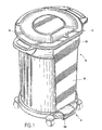
- Fig 1 is an assembled perspective view of the subject container dolly.
- Fig 2 is an exploded perspective view thereof.
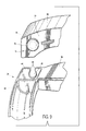
- Fig 3 is a top plan view thereof.
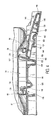
- Fig 4 is a sectional view through the container bottom and dolly foot pedal assembly, shown in the unlatching condition, taken along the line 4-4 of Fig 3.
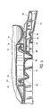
- Fig 5 is a sectional view through the container bottom and dolly foot pedal assembly, shown in the latched condition taken along the line 5-5 of Fig 3.
- Fig 6 is an enlarged perspective view of the food pedal assembly.
- Fig 7 is a top plan view of the dolly.
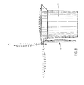
- Fig 8 is a side elevation view of the container illustrating the range of lid movement.
- Fig 9 is an enlarged exploded perspective view of the pivotal attachment between lid and the container handle.
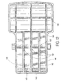
- Fig. 10 is a bottom plan view of the container.
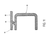
- Fig. 11 is a sectional view through the lid to container latch, taken along the line 11-11 of Fig. 10.
- Fig. 12 is a bottom plan view of the foot pedal.
- the subject assembly comprises three primary plastic, injection molded components; a refuse container 10, a lid 12, and a dolly 14.
- Suitable commercial grade polyethylene can be utilized in the formation of such components by conventional plastic molding techniques.
- the container 10 is generally cylindrical, comprising forward radiussed sidewalls 16.
- a rearward sidewall 18 of the container is substantially planar, having vertical edges which intersect the radiussed sidewalls 16, making the container generally D-shaped in cross- section.
- the sidewalls 16, 18 extend from a lower container end 20 to an upper peripheral rim 22.
- the handle 24 comprises spaced apart side plates 26, 28, each having an inward end connected to the sidewalls 16-18 and a U-shaped in section cross bar 30 connecting outward ends of the plates 26, 28.
- the cross bar 30 is of elongate configuration, radiussed across the bottom and forming a channel 32 along the top.
- the handle 34 likewise comprises spaced apart side plates 36, 38, and a U-shaped in section, elongate cross bar 40.
- Cross bar 40 includes a dependent U-shaped channel 42 extending between end walls 44. Extending downwardly into each end wall 44 from an upper edge is a pivot pin slot 46 having a circular, relatively large lower portion and a narrow pinch point 48 at the upper mouth.
- a vertically extending, outwardly projecting retention flange 45 is formed to extend along opposite side plates 36, 38 of the container handle 34.
- the container 10 has a generally flat bottom surface 50 and a pair of diametrically opposed hand recesses 52 which extend upward into the surface 50 at a location below the handles 24, 34.
- the bottom surface 50 comprises a further central recess 54 of elongate, generally elliptical shape, defined by a dependent peripheral skirt 56. Extending along linear ends of the recess 54 are horizontal flanges or ledges 58, 60. The flanges 58, 60 are spaced apart and are projected in opposition as best shown by Figs. 4 and 10.
- FIGS. 2 and 9 illustrate the configuration of the lid 12.
- the lid component 12 comprises a domed top surface 62 that merges along a peripheral edge with a dependent skirt.
- the skirt includes radiussed forward portion 64 and a planar rearward portion 66 such that the lid 12 is of a general D-shape to compliment the shape of the container 10.
- a pair of spaced apart arms 68, 70 extend outward from radiussed skirt portion 64, each arm 68, 70 having an inwardly directed surface 72.
- a hinge pin 74 projects inward from each arm 68, 70 and comprises a large diametered circular head 76 and a smaller diametered stem 78. Extending along each surface 72 adjacent each hinge pin 74 is an elongate retention flange 80.
- the dolly 14 is constructed to have a circular, generally planar top surface 82.
- Two diametrically opposite registration protrusions 84, 86 extend upward from surface 82, each complementarily shaped to the hand recesses 52 in the bottom of container 10.
- Four integrally molded spaced apart caster sockets 88 project outward from the dolly 14, each having a downwardly opening axial bore adapted to receive the upwardly projecting post 92 of a caster 90.
- the dolly 14 has radiussed side walls 94 which extend peripherally rearward from a forward end of the dolly, and a planar vertical step crosses the dolly at a rearward end, marking the rearward boundary of surface 82.
- a foot pedal cavity 98 extends downwardly into the top of the dolly at the rearward end to a bottom floor.
- the floor comprises a concave forward surface 100, a sharply inclined intermediate surface 102, and a ramped rearward surface 104.
- a through opening 106 In front of the forward cavity surface 100 is a through opening 106 that extends through the dolly from a top side to a bottom side.
- the cavity 98 is defined by opposed sidewalls 112, 113 into each of which an inverted U-shape pivot post socket 108 extends, positioned along cavity 98 at the concave surface 100.
- a detent 110 extends into a top edge of sidewalls 112, 113 above each of the sockets 108.
- a central region 114 of the dolly 14 is molded to provide a planar bridging surface 116, as best shown in Figs. 2, 4, and 7.
- a forwardly disposed upwardly directed, tine member 118 is joined to a forward end of the bridging surface by a reversely formed bight portion 120, and a rearwardly disposed, upwardly directed, tine member 122 is joined to a rearward end of the bridging surface 116 by a reversely formed bight portion 124.
- the line 20 members 118, 122 are rectangular plates in con-figuration, projecting upward from the surface 116 at complimentary divergent angles; member 118 at approximately an obtuse angle of 100 degrees inclination and member 122 at an acute angle of 80 degrees of inclination.
- the tine members represent cantilevered spring plates for latching purposes explained below.
- the forward tine member 118 has an upper formed over end portion 128 S that presents a downwardly angled upper beveled surface 130.
- the rearward tine member 122 has an upper formed over end portion 132 that presents a downwardly angled upper beveled surface 134. While the upper end portions 128, 132 of the tine members are at equal elevation, the bight connective portion 120 of forward tine member 118 is shorter, as will be appreciated by Figs. 4 and 5, and the bight connective portion 124 of rearward tine member 122 is longer as shown. Consequently, tine member 118 is shorter than tine member 122 and has less resiliency and flex. Member 122 is, to the contrary, longer and is therefore more flexible in lateral directions toward and away from the bridging surface 116.
- the dolly is an integrally molded unit that requires no consumer assembly other than the casters and incorporates, through tine members 118, 122, integral latching members of resilient and flexible plastic construction.
- the dolly further includes an actuating foot pedal 138, the pedal having a rearwardly disposed flat foot plate 140, five intermediately located separate and spaced apart pivot bearing portions 142 formed as integral, semi-circular dependent radiussed portions of three longitudinal flanges 143 and side portions of a dependent peripheral skirt 146 or, alternately, a single intermediately located pivot bearing portion may be formed extending the approximate width of the pedal 138.
- a forward actuating plate 144 extends forwardly from the pedal 138.
- the pedal 138 is integrally molded as one body.
- the dependent peripheral skirt 146 extends about the periphery of the pedal 138 and spaced apart support flanges 148, 150 transversely span the underside of the foot plate 140.
- the bearing portion is formed as comprising the collective radiussed bottom surfaces 152 of the dependent flanges 143 and the radiussed top surface 154.
- wing extensions 156, 160 Extending outward from opposite ends of the surface 154 are wing extensions 156, 160 having a radiussed, downwardly concave shape.
- the forward end portion 160 of the pedal 138 is downwardly formed at an acute angle and represents the pedal portion which engages tine member 122 as described below.
- the hinged lid 12 is operated by a one-hand procedure in a convenient manner.
- the lid 12 is fully and easily detached from the container 10 by simple upwards disengagement of the lid hinge pins 74 from the container bearing slots 46 by passing the pins 74 past the pinch points 48, to substantial advantage.
- the upward disengagement motion is easy and fast, as the hinge pins are conveniently accessible.
- the weight of the lid will always be positively supported by the container bearing slots 46 or container rim regardless of the position of the lid.
- the user of the container by intended design and orientation of the handles, naturally will stand adjacent to the flat side 18 of the container to lift and carry the container.
- the flat side 18 enables the user to carry the container closer to the body, making for enhanced comfort and more efficient application of lifting force.
- the orientation of the lid provides substantial advantage.
- the user can by single handed operation, open the lid by lifting handle 162 and rotate into the vertical, orientation shown in Fig. 8 without moving from the user's customary location against side 18. In the lid open condition, the user can move the container or insert matter into the container without moving.
- the hinge pins 74 are of a head and stem configuration and are sized relative to the slots 46. It will be appreciated that, in the configuration shown, it is not necessary to have a head on the end of the hinge pin stem 78. If one is used, its diameter must be greater than the stem diameter in order to be useful. If a head is not used on the hinge pin stem, then preferably the stem should be long enough to sufficiently prevent the hinge pin from inadvertently dislodging from the slots 46. The distance between the pinch points 48 should be smaller than the diameter of the hinge pin stem 78 and large enough to allow a "snap" removal of the hinge pin stem from the slots 46. In short, the sizing of the slots 46 and the stems 78 of the hinge pins are complementary and interdependent.
- retaining tabs or flanges 45, 80 on the lid arms 68, 70 as seen in Figs. 2, 9, and 11 must be sized relative to each other to mutually engage in order to retain the lid in a fully open position and yet allow subsequent closure. Locking the lid open assists during loading and dumping of the container 10, Fig. 11 shows the ramped sides of the abutting flanges 45, 80 that facilitate the interference progression of the lid flange 80 over the container flange 45 as the lid assumes a fully open, vertical position. The ramped sides further facilitate subsequent reverse progression of the flange 80 over the flange 45 as the lid is closed.
- the position of the pedal in the quiescent, or released position of Fig. 5 is such that the surface 160 of the actuating plate 144 abuts against the outward surface of the line member 122.
- the angle of decline of surface 160 is complementary to the angle of incline of tine member 122 so that the surfaces thereof meet flush as shown.
- the foot plate 140 is raised above the cavity floor portion 104 and prevented from falling by the tine member 122 keeping the actuating plate 144 end from rising.
- the pedal 138 and the cavity 98 are configured pursuant to the above, other configurations for pivotally mounting the pedal 138 into one end of the dolly may be utilized if so desired.
- a pivot rod securement of the pedal within the cavity can be used, although the subject preferred embodiment offers the advantage of a fastenerless method of assembly with no tools required.
- a user need only lift the container (preferably from a location adjacent the flat side thereof) and, from a standing position, lower the container to its final destination upon surface 82.
- Guidance is provided by passage of registration protrusions 84, 86 into hand recesses 52, to facilitate engagement of the container 10 with tine members 118, 122.
- inward ends of the container retention flanges 58, 60 engage the tine surfaces 134, 130, respectively, and force the tine members inward until the distance between tine ends 32 is sufficiently narrow to allow the container retention flanges 58, 60 to pass.
- the tine members 118, 122 resiliently snap outward and back into their respective quiescent orientations.
- the return of the line members 118, 122 is accompanied by a positive audible sound and tactile feel as the underside of line ends 32 latch over the top of the flanges 58, 60. Accordingly, a user will positively know that a secure lock has been achieved.
- the registration protrusions 84 and 86 securely engaged within container hand recesses 52 serve as holding blocks to take lateral and rotational stress off the tine members 118 and 122.
- the combined cooperative effect of the protrusions 84, 86 and the latching tine members 118, 122 result in a secure, rotationless interface between the container bottom and the dolly.
- the container and dolly can be manipulated by the user from adjacent the flat container side.
- the dolly fits beneath the container such that the curvilinear side of the container can be maneuvered into a corner for storage.
- the flat side of the container can be stored against a wall if so desired to conserve space.
- the foot plate 140 is always accessible to the user from a position adjacent the flat container side, since plate 140 projects rearward and beyond the flat container side 18.
- the foot plate 140 is pressured downward as shown in Fig. 4, bottoming out against the surface 104. Pivotal movement of the plate downward moves actuation plate 144 upward and end portion 160 presses tine member 122 inward until tine end 132 clears container flange 58. Thereupon, the container can be moved laterally and/or upwardly until the opposite tine member end 128 clears flange 60, enabling the container to be lifted up and clear of the dolly. Inward movement of tine member 122 is rendered easier by the relative height of the member which makes the cantilevered tine more flexible and easier to move. Conversely, the relatively low height of tine member 118 makes it relatively stiff, which contributes to enhancing the integrity of the resulting lock.
- a user need not touch the dolly, bend, or invert the container in order to accomplish attachment of the container to the dolly. Such can be achieved by simple downward movement of the container to the dolly top surface. Similarly, disattachment of the container does not require the user to grasp the dolly, bend, or invert the container buy hand.
- the subject invention facilitates more frequent emptying of the container by the user at shorter intervals, and thereby the container is less full. State of the art dolly and container assemblies are so cumbersome to separate that a user is more inclined to resist emptying the container until it is entirely full or emptying the container with the dolly still attached.
- the subject invention provides a latch that cannot be compromised or altered by use of the combined container and dolly.
- the encountering of curbs or thresholds by the wheels of the subject dolly will not alter the security of the attachment to render disengagement of the dolly more difficult since the attachment of the prevent invention is not achieved by rotary movement.
- the user need not be concerned that the attachment has loosened into an unsafe condition through use or tightened beyond the user's capacity to free it.
- the subject invention comprising four molded parts is economical to manufacture and, because no assembly hardware is required, the cost of the assembly is further minimized. In addition, there are no parts that will require frequent replacement from repeated use. Thus, the assembly is durable and economical and represents a substantial improvement over more costly and less durable conventional container and dolly assemblies.
- the subject invention comprises a dolly and container that assemble by linear movement between the container and the dolly, preferably but not necessarily linear movement of the container toward the stationary dolly.
- rotation of the dolly or container is not necessary and a touching of the dolly to initiate such rotation is not necessary. Rather, the container is simply lowered downward and establishes latching engagement without contact between the user and the dolly.
- the dolly and the container have interfitting protrusions and recesses, respectively that interfit to register the container upon the dolly support surface and further to prevent any rotational movement therebetween.
- the recesses of the container into which the protrusions of the dolly fit are hand recesses in the container bottom.
- the hand recesses are located below the container handles and serve to receive the user's hand and facilitate a lifting of the container by the bottom when the container is separated from the dolly.
- each of the container recesses serve two functions: one as a hand recess for lifting the container and secondarily as a registration recess.
- the latching tines engage the lower portion of the container and as they snap over the container flanges, emit an audible "click" to communicate to the user that a successful attachment has been achieved.
- the audible sound thus acts to reassure the user and the absence of the sound indicates a lack of success.
- the only direction by which the container can become disattached is vertically (i.e., lifting the container after its release), it is not likely to become inadvertently unattached from the dolly during use.
- the pedal member is foot actuated which makes it possible to disassemble the container from the dolly without the user touching the dolly.
- the foot actuated pedal is pivotally attached to the dolly but other modes of operation will be apparent.
- a slide mechanism can be devised that, subject to foot pressure, moves linearly to press the tine 122 out of engagement with the container.
- the container travels in a linear vertical direction relative to the dolly during the attachment procedure: i.e. it is lowered to the dolly by the handles by an erect user.
- the reverse linear direction is necessary for separation. It is the linear, non-rotary nature of the separation and attachment movements that makes the assembly resistant to the inadvertent separation attendant rotationally attached containers and dollies.
- a horizontal linear attachment of the container to the dolly may also be constructed pursuant to the teachings herein.
- the foot pedal can be configured to depress one or both of the tines to free the container from the dolly. While not as convenient to assemble as the preferred embodiment which contemplates relative movement in the vertical direction, the horizontal linear attachment of the container to the dolly would provide some of the advantages, such as resistance to inadvertent separation, over the rotationally attached state of the art assemblies.
- the invention is not intended to be so restricted.
- the number and location of the dolly tine members may be varied.
- the dolly need not necessarily be used in conjunction with containers having the subject flat side, but may be used on conventional cylindrical containers.
- Other variations, obvious to those skilled in the art, will also be readily apparent.
Landscapes
- Engineering & Computer Science (AREA)
- Mechanical Engineering (AREA)
- Chemical & Material Sciences (AREA)
- Combustion & Propulsion (AREA)
- Transportation (AREA)
- Refuse Receptacles (AREA)
- Handcart (AREA)
- Details Of Rigid Or Semi-Rigid Containers (AREA)
Description
Claims (20)
- A refuse container having an elongate receptacle body (10) including a bottom surface (20) and radiussed sidewall (16) extending from the bottom surface to an upper rim (22) and defining an upwardly opening receptacle cavity;a wheeled dolly (14) including a platform body having an upper support surface (82) for supporting the elongate receptacle body (10) and a plurality of wheels (90) affixed to an underside of the platform body, whereby the platform body is mobile;an attachment means for detachably connecting the dolly support surface (82) to the bottom container surface (20); characterised by disconnect means for disconnecting the dolly from the bottom container surface, said disconnect means including a foot activated pedal member (138) mounted to one side of the dolly (14).
- A refuse container according to claim 1, wherein the foot pedal member comprises an outer foot plate (140), an intermediate portion (142) pivotally coupled to the dolly, and an inner actuating portion (144).
- A refuse container according to claim 1 or 2, wherein the receptacle bottom surface (20) has at least one ledge flange (58,60) and the dolly includes at least one latch tine (118,122) projecting upward and positioned to engage the ledge flange (58,60) as the receptacle bottom surface (20) is positioned upon the dolly support surface (82).
- A refuse container according to claim 1, 2 or 3, wherein the dolly upper support surface (82) has a forward portion shaped and dimensioned to reside below the receptacle body bottom surface and a rearward portion at the one side of the dolly projecting outward and beyond a rearwardly disposed sidewall of the receptacle body with the receptacle body positioned upon the dolly support. surface, and the foot activated pedal member (138) has a foot actuated end portion (140) positioned to project outward and beyond the rearward sidewall (18) of the receptacle body (10) with the receptacle body positioned upon the dolly support surface (82).
- A refuse container according to any preceding claim, wherein the receptacle body includes a lid member (12) pivotally attached to at least one of first and second handles (24,34) and pivoting in a direction parallel to the rearward sidewall (18) of the receptacle body from a closure position upon the receptacle body upper rim to an open position adjacent the receptacle body radiussed sidewall.
- A refuse container according to any preceding claim, wherein the wheeled dolly includes a foot pedal cavity (98) defined by sidewalls (112,113) and a bottom surface (104) and extending downwardly from the upper support surface (82) and the cavity extending from an inward cavity end to a peripheral outward cavity end;locking means (118,112) mounted to the platform body for engaging and releasably locking the refuse container to the support surface; andthe foot pedal member (138) mounted within the cavity (98) and having an inward end (144) for disengaging the locking means responsive to movement of the pedal member.
- A refuse container according to claim 6, wherein the foot pedal has an outwardly disposed, foot actuated horizontal plate portion (140) for initiating pivotal movement of the pedal member.
- A refuse container according to claim 6 or 7, wherein the locking means comprise at least a first said upwardly projecting tine member (122) having a lower end mounted to the platform body and a remote end (134) for engaging a bottom surface of the refuse container (10) and the tine member moving out of engagement with the container bottom surface (20) responsive to pressure applied by the pedal member inward end (144).
- A refuse container according to any of claims I to 5, wherein the attachment means includes locking means (118,112) mounted to the platform body for releasably locking the refuse container (10) to the support surface (82), the locking means including lock actuation means (128,132) responsive to linear movement of the container relative to the platform body support surface for establishing locking engagement between the refuse container and the support surface.
- A refuse container according to claim 9, wherein the locking means emit an audible sound to communicate successful achievement of locking engagement between the refuse container (10) and the support surface (82).
- A refuse container according to claim 9 or 10, wherein the lock actuation means (128,132) is responsive to downward movement of the container (10) toward the platform body support surface (82).
- A refuse container according to claim 9, 10 or 11, wherein the platform body and the platform support surface (82) remain stationary during attachment and release of the container (10) from the platform body support surface (82).
- A refuse container according to any preceding claim, wherein the container attaches to the platform body support surface by being lowered downward to the support surface.
- A refuse container according to any preceding claim, further, comprising registration means for registering the container (10) upon the support surface (82) to inhibit relative rotary motion.
- A refuse container according to any preceding claim, wherein the' elongate receptacle body is defined by a bottom surface (20) and sidewalls (16,18) extending from the bottom surface (20) to an upper rim (22) and further characterised in that the sidewalls have a rearward substantially planar sidewall (18) and radiussed forward sidewalls (16) whereby the receptacle body has a substantially D-shaped cross-sectional configuration; and the refuse container further includes
first and second handles (24,34) extending outward from opposite sides of the radiussed forward sidewalls (16), positioned proximate the upper rim (22) and proximate the planar rearward sidewall (18). - , A refuse container according to claim 15, wherein the handles each include spaced apart support plates (26,28,36,38) each having an inner end connected to the body radiussed sidewalls and a remote outer end, and a cross member (30,40) having opposite ends connected to the remote outer ends of the support plates.
- A refuse container according to claim 15 or 16, wherein the foot activated pedal member is positioned proximate to the dolly support surface planar rearward surface and accessible to a user stationed adjacent the planar rearward sidewall of the receptacle body.
- A refuse container according to any preceding claim wherein the lid member (12) has a substantially D-shaped planar configuration, is pivotally coupled to the receptacle body (10) and pivots between a first position upon the upper rim and a second position adjacent the receptacle body radiussed sidewall.
- A refuse container according to claim 18, wherein the lid member (12) and the one handle (24) have an engaging flange (80) and a detent (32) respectively for releasably locking the lid member in the second position.
- A refuse container according to claim 19, wherein the lid member (12) has a central body and spaced apart arms (68,70) extending outward therefrom, the arms having remote ends adapted to pivotally attach to the opposite ends of one handle cross-member (42) of the container (20).
Applications Claiming Priority (3)
| Application Number | Priority Date | Filing Date | Title |
|---|---|---|---|
| US08/513,268 US5758888A (en) | 1995-08-10 | 1995-08-10 | Refuse container and dolly having foot activated release mechanism |
| US513268 | 1995-08-10 | ||
| PCT/US1996/011381 WO1997006080A1 (en) | 1995-08-10 | 1996-07-08 | Refuse container and dolly having foot activated release mechanism |
Publications (2)
| Publication Number | Publication Date |
|---|---|
| EP0781246A1 EP0781246A1 (en) | 1997-07-02 |
| EP0781246B1 true EP0781246B1 (en) | 2000-03-22 |
Family
ID=24042544
Family Applications (1)
| Application Number | Title | Priority Date | Filing Date |
|---|---|---|---|
| EP96924377A Expired - Lifetime EP0781246B1 (en) | 1995-08-10 | 1996-07-08 | Refuse container and dolly having foot activated release mechanism |
Country Status (7)
| Country | Link |
|---|---|
| US (1) | US5758888A (en) |
| EP (1) | EP0781246B1 (en) |
| JP (1) | JP2001519749A (en) |
| AU (1) | AU6484996A (en) |
| BR (1) | BR9606551A (en) |
| DE (1) | DE69607311T2 (en) |
| WO (1) | WO1997006080A1 (en) |
Families Citing this family (64)
| Publication number | Priority date | Publication date | Assignee | Title |
|---|---|---|---|---|
| US5704625A (en) * | 1996-02-02 | 1998-01-06 | Rubbermaid Commercial Products Inc. | Trash container carrier |
| US6038734A (en) * | 1998-05-21 | 2000-03-21 | Facchin; Girolamo Angelo | Bearing caster |
| DE29817190U1 (en) | 1998-09-25 | 1998-12-24 | Gebr. Otto KG, 50968 Köln | Waste bin |
| US6053354A (en) * | 1998-10-09 | 2000-04-25 | Contico International, Inc. | Container with hinged lid assembly |
| US6651992B1 (en) | 2000-10-02 | 2003-11-25 | Albert Lee Smith, Sr. | Container with integral dolly |
| US6705577B1 (en) * | 2001-08-08 | 2004-03-16 | David E. Grimes | Receptacle support and method |
| US6488293B1 (en) * | 2001-11-16 | 2002-12-03 | Eagle Manufacturing Company | Drum dolly |
| US20030230576A1 (en) * | 2002-06-17 | 2003-12-18 | Tsong-You Lin | Pedal assembly |
| US8152019B1 (en) | 2002-08-23 | 2012-04-10 | Xtreme Plastics, Llc | Reinforced dust pan and refuse container |
| US7185783B1 (en) | 2002-08-23 | 2007-03-06 | Miller David H | Fastcan |
| US7017773B2 (en) * | 2002-09-09 | 2006-03-28 | Rehrig Pacific Company | Waste container |
| KR20040025126A (en) * | 2002-09-18 | 2004-03-24 | 주식회사 세원지오신테크 | Method for constructing a wall for preventing the leakage of contaminant |
| DE10306486A1 (en) * | 2003-02-14 | 2004-08-26 | Shu-Pei Huang | Hinged lid container and especially waste bin has widening ring fitted on foot section, protruding over foot section's circumferential edge and standing on floor surface when bin is upright |
| US6874836B1 (en) | 2003-04-16 | 2005-04-05 | Covered trash receptacle | |
| USD520702S1 (en) | 2003-12-12 | 2006-05-09 | Miller David H | Outdoors refuse container |
| US7044323B2 (en) * | 2003-12-23 | 2006-05-16 | Simplehuman Llc | Detachable foot pedal for trash can |
| US7530578B2 (en) * | 2004-11-17 | 2009-05-12 | Continental Commercial Products, Llc | Step-on receptacle with tip prevention |
| US20060188362A1 (en) * | 2005-02-20 | 2006-08-24 | Link Robert A | Tilting drum dolly |
| US7427076B2 (en) * | 2005-03-22 | 2008-09-23 | David Christopher Gwin | Base tool caddy for janitorial cleaning supplies |
| US7364172B1 (en) * | 2005-04-14 | 2008-04-29 | Brian Archer | Device for transforming a stationary bucket into a rolling bucket, functioning as a lid, and also facilitating attachment of a substance removal device |
| US20070045974A1 (en) * | 2005-08-24 | 2007-03-01 | Young Roger L | Wheeled can for bar refuse |
| US20070045323A1 (en) * | 2005-08-25 | 2007-03-01 | Kroiss Cindy L | Vomit container |
| US7516865B1 (en) * | 2005-11-14 | 2009-04-14 | Reginald Pierre | Deodorized waste receptacle |
| US8308004B2 (en) * | 2005-11-22 | 2012-11-13 | Rexam Healthcare Packaging Inc. | Dispensing package having non-removable and non-rotatable dispensing closure |
| US7281720B1 (en) * | 2006-05-16 | 2007-10-16 | Richards Robert M | Drum transport cart |
| USD549920S1 (en) | 2006-07-26 | 2007-08-28 | Impact Products, Llc | Dolly |
| US20080035660A1 (en) * | 2006-08-12 | 2008-02-14 | Dow Paul E | Medicine dispensing system |
| US20080084041A1 (en) * | 2006-10-05 | 2008-04-10 | Dukes Stephen A | Receptacle dolly |
| US20080136202A1 (en) | 2006-12-07 | 2008-06-12 | Rubbermaid Incorporated | Scoop |
| USD566366S1 (en) * | 2007-07-18 | 2008-04-08 | George Aguilar | Collection container |
| US7954830B2 (en) * | 2008-02-19 | 2011-06-07 | Rubbermaid Incorporated | Ice transport system |
| GB2473302B (en) * | 2009-12-18 | 2011-07-27 | Magmatic Ltd | Storage containers |
| US20110173769A1 (en) * | 2010-01-21 | 2011-07-21 | Incredible Plastics, Inc. | Edge apparatus attachable to receptacle |
| WO2012150920A1 (en) * | 2010-01-22 | 2012-11-08 | Carlisle Foodservice Products Incorporated | Food pan carrier |
| US9266548B1 (en) * | 2010-05-18 | 2016-02-23 | Worldwide Integrated Resources, Inc. | Combination trash can dolly and mop bucket and combination janitorial cart and mop bucket |
| US8256778B1 (en) * | 2010-05-18 | 2012-09-04 | Worldwide Integrated Resources, Inc. | Combination trash can dolly and mop bucket |
| USD655183S1 (en) | 2010-08-26 | 2012-03-06 | Huhtamaki, Inc. | Container and lid |
| USD643740S1 (en) | 2010-08-26 | 2011-08-23 | Huhtamaki, Inc. | Container and lid |
| USD651780S1 (en) * | 2011-03-28 | 2012-01-03 | Grasteit Benjamin M | Trash can having a trash scoop and a trash barrier |
| US9181027B2 (en) * | 2011-06-01 | 2015-11-10 | Jonathan Diaz | Trash receptacle securing system |
| US8419023B1 (en) | 2011-09-01 | 2013-04-16 | George W. Landrum, Jr. | Trash carryall with removable cylinder |
| US20140217688A1 (en) * | 2013-02-05 | 2014-08-07 | Cascade Engineering, Inc. | Trash/recycling cart |
| US9150234B2 (en) * | 2013-03-15 | 2015-10-06 | San Jamar, Inc. | Tote transport |
| US20140319156A1 (en) * | 2013-04-30 | 2014-10-30 | Thomas Casperite | Bear Canister Apparatus |
| US9446778B2 (en) * | 2014-08-20 | 2016-09-20 | Toyota Motor Engineering & Manufacturing North America, Inc. | Start-assist pedal for transport dolly |
| US9994244B2 (en) | 2014-12-24 | 2018-06-12 | Veltek Associates, Inc. | Cart with removable wheel base |
| US11555576B2 (en) | 2014-12-24 | 2023-01-17 | Veltek Associates, Inc. | Stationary transfer platform and cleaning device for supply transport device |
| WO2016106219A1 (en) | 2014-12-24 | 2016-06-30 | Veltek Associates, Inc. | Cart with removable wheel base |
| US20160356640A1 (en) * | 2015-06-05 | 2016-12-08 | Joseph M. Freeman | Receptacle Scale for Measuring a Weight of a Receptacle |
| USD809730S1 (en) | 2015-12-22 | 2018-02-06 | Veltek Associates, Inc. | Cart |
| US9738444B1 (en) | 2016-02-02 | 2017-08-22 | Suncast Technologies, Llc | Commercial grade wheeled refuse receptacle with lid |
| USD825129S1 (en) * | 2016-07-21 | 2018-08-07 | Suncast Technologies, Llc | Trash can |
| USD831292S1 (en) * | 2017-04-05 | 2018-10-16 | Suncast Technologies, Llc | Wheeled cart |
| USD840126S1 (en) | 2017-04-07 | 2019-02-05 | Incredible Solutions, Inc. | Trash can |
| US11684444B2 (en) * | 2019-05-02 | 2023-06-27 | Stryker Corporation | Height adjustable kick bucket and height adjustable stand |
| US12082670B2 (en) * | 2019-07-17 | 2024-09-10 | Valet Living, Llc | Tote-dolly system |
| US12296881B2 (en) * | 2019-07-17 | 2025-05-13 | Valet Living, Llc | Tote-dolly system |
| US20220135319A1 (en) * | 2019-11-14 | 2022-05-05 | Plastic Recovery Technologies Corporation | Bottom assemblies for commercial waste containers |
| US11203369B2 (en) * | 2019-12-27 | 2021-12-21 | Howard McMillan | Dolly assembly |
| WO2021150661A1 (en) | 2020-01-21 | 2021-07-29 | Stryker Corporation | Height adjustable medical bucket |
| US12291394B1 (en) * | 2021-03-03 | 2025-05-06 | Jason Hoagland | Trash can and method of use |
| US12421026B2 (en) * | 2021-09-14 | 2025-09-23 | Cfs Brands, Llc | Trash bin dolly system |
| US20230242335A1 (en) * | 2022-02-03 | 2023-08-03 | Jason Craig Turman | Divided Trash Can |
| USD1113044S1 (en) | 2024-05-01 | 2026-02-10 | Findlay Machine & Tool, Llc | Dolly for trash can |
Family Cites Families (37)
| Publication number | Priority date | Publication date | Assignee | Title |
|---|---|---|---|---|
| US3125353A (en) * | 1964-03-17 | Transport container with removable under-carriage or truck | ||
| US806885A (en) * | 1905-03-07 | 1905-12-12 | George Focht | Garbage or ash can. |
| US926288A (en) * | 1909-01-27 | 1909-06-29 | William E Rice | Barrel-truck. |
| US2532165A (en) * | 1945-07-02 | 1950-11-28 | Continental Can Co | Container for refuse |
| US2615663A (en) * | 1947-03-14 | 1952-10-28 | Bertis F Hamilton | Waste can closure operator and support |
| US2549572A (en) * | 1948-04-26 | 1951-04-17 | Anthony M Campanelli | Step-on can with dustpan |
| US2811329A (en) * | 1955-06-30 | 1957-10-29 | Fed Tool Corp | Step-on type waste receptacle unit |
| US2910206A (en) * | 1957-01-23 | 1959-10-27 | Continental Can Co | Refuse can with foot pedal closure opening means |
| US3269580A (en) * | 1965-10-14 | 1966-08-30 | Nvf Company | Transportable container |
| US3390804A (en) * | 1966-09-02 | 1968-07-02 | Thomas P. Morgan | Combination trash receptacle and dustpan lid |
| US3618795A (en) * | 1969-08-18 | 1971-11-09 | United States Steel Corp | Charging box for an open hearth furnace |
| US3858929A (en) * | 1973-03-29 | 1975-01-07 | Rubbermaid Commerical Products | Tilt truck frame with removable tub |
| US3904218A (en) * | 1973-10-31 | 1975-09-09 | Raymond Lee Organization Inc | Complementary trash can unit |
| US4081105A (en) * | 1977-03-18 | 1978-03-28 | Societe Industrielle et Commerciale de Transformation des Plastiques "Sicopal" | Pedal bin |
| USD253932S (en) | 1977-09-22 | 1980-01-15 | Mockler H Ray | Combined covered receptacle and removable dolly therefor |
| US4217073A (en) * | 1978-05-05 | 1980-08-12 | Herman Miller, Inc. | Material handling system |
| US4222580A (en) * | 1978-06-29 | 1980-09-16 | Joseph Krokonko | Refuse bag holder assembly |
| USD261720S (en) | 1979-08-31 | 1981-11-10 | Rubbermaid Incorporated | Step-on wastebasket |
| US4313612A (en) * | 1980-02-20 | 1982-02-02 | Rubens Robert A | Convertible trash container carrier |
| US4279357A (en) * | 1980-03-14 | 1981-07-21 | Robinson William W | Garbage can assembly with lid anchoring means |
| US4420168A (en) * | 1982-06-10 | 1983-12-13 | Terra Bella Industries | Device for handling refuse or the like material |
| US4785964A (en) * | 1987-10-19 | 1988-11-22 | Mobil Oil Corporation | Step-on wastebasket |
| US4865214A (en) * | 1987-10-19 | 1989-09-12 | Mobil Oil Corporation | Step-on wastebasket |
| US4821903A (en) * | 1988-04-21 | 1989-04-18 | Hayes James K | Trash bin cart and bin assembly |
| US4953740A (en) * | 1989-03-06 | 1990-09-04 | Mobil Oil Corporation | Wastebasket having lid hinge and actuating mechanism protector |
| US4930653A (en) * | 1989-07-24 | 1990-06-05 | Daniel Machado | Refuse container caddy apparatus |
| USD322350S (en) | 1990-01-12 | 1991-12-10 | Rubbermaid Incorporated | Step-on wastebasket |
| US5005729A (en) * | 1990-01-22 | 1991-04-09 | Hollman Kevin A | Displaceable waste basket |
| US5074572A (en) * | 1990-03-14 | 1991-12-24 | Rubbermaid Commercial Products Inc. | Refuse container dolly having integral alignment means |
| US4995529A (en) * | 1990-03-16 | 1991-02-26 | Sher Cheng Hsien | Structure of garbage can assembly |
| US5141124A (en) * | 1990-04-09 | 1992-08-25 | The Heil Co. | Refuse container with snap-on cover |
| NL9001796A (en) * | 1990-08-10 | 1992-03-02 | Curver Rubbermaid Bv | PEDAL BUCKET WITH LID. |
| USD327756S (en) | 1990-08-29 | 1992-07-07 | Sterilite Corporation | Combined storage bins and cart therefor |
| USD332852S (en) | 1991-06-25 | 1993-01-26 | Rubbermaid Commercial Products Inc. | Step-on waste receptacle |
| US5230525A (en) * | 1991-06-25 | 1993-07-27 | Rubbermaid Commercial Products Inc. | Step-on waste container |
| US5472220A (en) * | 1994-09-30 | 1995-12-05 | Stephan; Gerard A. | Bucket dolly |
| US5599037A (en) * | 1995-03-17 | 1997-02-04 | Spickler; Christian D. | Golf bag holder |
-
1995
- 1995-08-10 US US08/513,268 patent/US5758888A/en not_active Expired - Fee Related
-
1996
- 1996-07-08 AU AU64849/96A patent/AU6484996A/en not_active Abandoned
- 1996-07-08 WO PCT/US1996/011381 patent/WO1997006080A1/en not_active Ceased
- 1996-07-08 JP JP50842897A patent/JP2001519749A/en active Pending
- 1996-07-08 BR BR9606551A patent/BR9606551A/en not_active Application Discontinuation
- 1996-07-08 DE DE69607311T patent/DE69607311T2/en not_active Expired - Fee Related
- 1996-07-08 EP EP96924377A patent/EP0781246B1/en not_active Expired - Lifetime
Also Published As
| Publication number | Publication date |
|---|---|
| AU6484996A (en) | 1997-03-05 |
| US5758888A (en) | 1998-06-02 |
| EP0781246A1 (en) | 1997-07-02 |
| WO1997006080A1 (en) | 1997-02-20 |
| JP2001519749A (en) | 2001-10-23 |
| BR9606551A (en) | 1998-07-21 |
| DE69607311D1 (en) | 2000-04-27 |
| DE69607311T2 (en) | 2000-07-13 |
Similar Documents
| Publication | Publication Date | Title |
|---|---|---|
| US5758888A (en) | Refuse container and dolly having foot activated release mechanism | |
| US4691840A (en) | Lid locking handle for waste container | |
| AU638662B2 (en) | Locking system for a waste receptacle | |
| US5230525A (en) | Step-on waste container | |
| US4423534A (en) | Vacuum cleaner handle lock | |
| US5611107A (en) | Latching mechanisms for wet/dry utility vacuum cleaner with detachable blower | |
| US5175891A (en) | Device for fixing a toilet seat and a toilet lid | |
| US5704625A (en) | Trash container carrier | |
| US7287665B2 (en) | Waste container | |
| CA1298810C (en) | Self-closing, press-to-open, dispensing closure | |
| US8640274B2 (en) | Toilet device | |
| JPH0761505A (en) | Rotary lid member for refuse container | |
| JPH03267202A (en) | Trash can dolly having integral matching means | |
| US20050257340A1 (en) | Wet/dry vacuum | |
| CA2524895C (en) | Waste container | |
| GB2300112A (en) | Portable cleaning container with a foot-actuated valve | |
| US6643891B1 (en) | Dustpan with locking handle and associated broom | |
| US20170029208A1 (en) | Roll-out cart with lid latch | |
| US5086954A (en) | Spray can actuation device with improved can retention | |
| WO2001060719A1 (en) | Bin lid lifting assembly | |
| US6644073B1 (en) | Containers | |
| CN1161026A (en) | A combination device of a container and a trolley with a detachable structure manipulated by feet | |
| CA3173871A1 (en) | Trash bin dolly system | |
| JPH0745441Y2 (en) | Garbage container | |
| JP2599087B2 (en) | Plastic containers used for garbage trucks |
Legal Events
| Date | Code | Title | Description |
|---|---|---|---|
| PUAI | Public reference made under article 153(3) epc to a published international application that has entered the european phase |
Free format text: ORIGINAL CODE: 0009012 |
|
| 17P | Request for examination filed |
Effective date: 19970324 |
|
| AK | Designated contracting states |
Kind code of ref document: A1 Designated state(s): DE FR GB |
|
| 17Q | First examination report despatched |
Effective date: 19980904 |
|
| GRAG | Despatch of communication of intention to grant |
Free format text: ORIGINAL CODE: EPIDOS AGRA |
|
| GRAG | Despatch of communication of intention to grant |
Free format text: ORIGINAL CODE: EPIDOS AGRA |
|
| GRAH | Despatch of communication of intention to grant a patent |
Free format text: ORIGINAL CODE: EPIDOS IGRA |
|
| RAP1 | Party data changed (applicant data changed or rights of an application transferred) |
Owner name: RUBBERMAID COMMERCIAL PRODUCTS LLC |
|
| GRAH | Despatch of communication of intention to grant a patent |
Free format text: ORIGINAL CODE: EPIDOS IGRA |
|
| GRAA | (expected) grant |
Free format text: ORIGINAL CODE: 0009210 |
|
| AK | Designated contracting states |
Kind code of ref document: B1 Designated state(s): DE FR GB |
|
| REF | Corresponds to: |
Ref document number: 69607311 Country of ref document: DE Date of ref document: 20000427 |
|
| ET | Fr: translation filed | ||
| PLBE | No opposition filed within time limit |
Free format text: ORIGINAL CODE: 0009261 |
|
| STAA | Information on the status of an ep patent application or granted ep patent |
Free format text: STATUS: NO OPPOSITION FILED WITHIN TIME LIMIT |
|
| 26N | No opposition filed | ||
| REG | Reference to a national code |
Ref country code: GB Ref legal event code: IF02 |
|
| PGFP | Annual fee paid to national office [announced via postgrant information from national office to epo] |
Ref country code: GB Payment date: 20020703 Year of fee payment: 7 |
|
| PGFP | Annual fee paid to national office [announced via postgrant information from national office to epo] |
Ref country code: FR Payment date: 20020709 Year of fee payment: 7 |
|
| PGFP | Annual fee paid to national office [announced via postgrant information from national office to epo] |
Ref country code: DE Payment date: 20020717 Year of fee payment: 7 |
|
| PG25 | Lapsed in a contracting state [announced via postgrant information from national office to epo] |
Ref country code: GB Free format text: LAPSE BECAUSE OF NON-PAYMENT OF DUE FEES Effective date: 20030708 |
|
| PG25 | Lapsed in a contracting state [announced via postgrant information from national office to epo] |
Ref country code: DE Free format text: LAPSE BECAUSE OF NON-PAYMENT OF DUE FEES Effective date: 20040203 |
|
| GBPC | Gb: european patent ceased through non-payment of renewal fee |
Effective date: 20030708 |
|
| PG25 | Lapsed in a contracting state [announced via postgrant information from national office to epo] |
Ref country code: FR Free format text: LAPSE BECAUSE OF NON-PAYMENT OF DUE FEES Effective date: 20040331 |
|
| REG | Reference to a national code |
Ref country code: FR Ref legal event code: ST |