EP0780954B1 - Machine électrique synchrone à aimants permanents adaptée à fonctionner à puissance constante sur une large plage de vitesse - Google Patents
Machine électrique synchrone à aimants permanents adaptée à fonctionner à puissance constante sur une large plage de vitesse Download PDFInfo
- Publication number
- EP0780954B1 EP0780954B1 EP96402797A EP96402797A EP0780954B1 EP 0780954 B1 EP0780954 B1 EP 0780954B1 EP 96402797 A EP96402797 A EP 96402797A EP 96402797 A EP96402797 A EP 96402797A EP 0780954 B1 EP0780954 B1 EP 0780954B1
- Authority
- EP
- European Patent Office
- Prior art keywords
- magnets
- rotor
- magnet
- rotor according
- flux
- Prior art date
- Legal status (The legal status is an assumption and is not a legal conclusion. Google has not performed a legal analysis and makes no representation as to the accuracy of the status listed.)
- Expired - Lifetime
Links
Images

Classifications
-
- H—ELECTRICITY
- H02—GENERATION; CONVERSION OR DISTRIBUTION OF ELECTRIC POWER
- H02K—DYNAMO-ELECTRIC MACHINES
- H02K1/00—Details of the magnetic circuit
- H02K1/06—Details of the magnetic circuit characterised by the shape, form or construction
- H02K1/22—Rotating parts of the magnetic circuit
- H02K1/27—Rotor cores with permanent magnets
- H02K1/2706—Inner rotors
- H02K1/272—Inner rotors the magnetisation axis of the magnets being perpendicular to the rotor axis
- H02K1/274—Inner rotors the magnetisation axis of the magnets being perpendicular to the rotor axis the rotor consisting of two or more circumferentially positioned magnets
- H02K1/2753—Inner rotors the magnetisation axis of the magnets being perpendicular to the rotor axis the rotor consisting of two or more circumferentially positioned magnets the rotor consisting of magnets or groups of magnets arranged with alternating polarity
- H02K1/278—Surface mounted magnets; Inset magnets
-
- H—ELECTRICITY
- H02—GENERATION; CONVERSION OR DISTRIBUTION OF ELECTRIC POWER
- H02K—DYNAMO-ELECTRIC MACHINES
- H02K21/00—Synchronous motors having permanent magnets; Synchronous generators having permanent magnets
- H02K21/12—Synchronous motors having permanent magnets; Synchronous generators having permanent magnets with stationary armatures and rotating magnets
- H02K21/14—Synchronous motors having permanent magnets; Synchronous generators having permanent magnets with stationary armatures and rotating magnets with magnets rotating within the armatures
Definitions
- the invention relates to an electric machine synchronous with permanent magnets adapted to operate at constant power over a wide speed range from base speed to maximum speed equal to three times at least this base speed as well as the rotor of such a machine.
- the invention applies in particular to the engine of electric vehicles, and more particularly to any type of motor requiring power operation constant over a wide speed range.
- a solution for vehicle traction electric cars involves combining a motor operating at constant torque and a gearbox.
- gearbox constitutes for a car manufacturer a heavy, bulky and expensive.
- an electric machine synchronous with permanent magnets which comprises a rotor whose the peripheral surface is substantially completely covered with magnets.
- These magnets are preferably magnets with high energy density, and are magnetized radially.
- This synchronous electric machine has also a stator constituting a polyphase armature and having on its inner peripheral surface teeth delimiting notches in which are wound coils, and dimmer means for vary the voltage and current crossing the turns, as well as the angular offset of the magnetic flux of the magnets compared to the flux of the polyphase armature.
- this synchronous machine operates at substantially constant torque until basic speed which is reached when the voltage of the current supplied to the machine reaches its maximum value.
- the latter is in the case of a motor vehicle electric traction nominal battery voltage equipping this vehicle.
- the variator which equips this machine is adapted to adjust no only the voltage and the current intensity the stator turns, but also the angular offset of the magnetic flux of the rotor magnets relative to the magnetic flux from the polyphase armature of the stator.
- Such a structure used mainly for servomotors, allows a maximum speed which is practically limited to about one and a half times the basic speed.
- a synchronous magnet motor of the concentration type flux includes a rotor fitted with magnets positioned radially with a direction of magnetization azimuth (or tangential), and pole pieces arranged between two adjacent magnets and acting as flux concentrators.
- the value of reluctance offered to the magnet flow on the motor shaft side is between ten times and twenty times the value of the reluctance offered to the flux of magnets on the side of the engine air gap.
- the announced goal of this structure is to achieve a synchronous motor capable of operating within a range of significant speeds, ranging from a given base speed to a maximum speed equal to four times this speed of based.
- a rotor of a synchronous electric motor comprising a frame comprising pole pieces projecting radially outward and carrying, between two adjacent pole pieces, one or more radially magnetized magnets.
- the side faces of magnets are distant from the respective side faces of the corresponding adjacent pole pieces.
- Rooms polar have a circular outer peripheral edge of radius significantly smaller than the radius of the rotor, which produces an air gap of variable size whose effect is unfavorable in terms of the flow component in the axis magnets.
- each magnet and the adjacent pole piece have the function of giving a substantially sinusoidal magnetic flux distribution to eliminate fluctuations in rotor torque and to obtain a regular rotation of the latter.
- This structure thus aims to obtain a very regular torque, very smooth, at low speed, which can be particularly interesting on a machine tool to obtain excellent machining quality making a classic subsequent step of rectification.
- This type of rotor is in no way suitable for equipping a machine capable of operating at constant power over a wide speed range and with a high power and high efficiency.
- the object of the present invention is to remedy to the aforementioned drawbacks of the known structures of synchronous permanent magnet electric machine, and offer a machine of the aforementioned type which is not very bulky, reliable, very economical, and that is specially adapted to operate at constant power over the wide speed range defined above.
- Another object of the invention is to propose a rotor adapted to equip such an electric machine synchronous.
- the synchronous permanent magnet electric machine of the type aforementioned is characterized in that the rotor comprises a predetermined number of pole pieces and between two pole pieces adjacent to at least one permanent magnet of predetermined thickness and magnetized radially or axially, each substantially radial wall of a magnet adjacent to the corresponding substantially radial wall of a pole piece being spaced from this wall substantially radial from a predetermined distance so to prevent any risk of demagnetization of the magnet by presence of a maximum current likely to cross the machine, especially in the event of a short circuit the latter.
- pole pieces which would have the effect of channel the flow of the rotor by creating, under the conditions extremes encountered in traction motors, in these parts and in the vicinity of these flows likely to demagnetize the magnets subjected to these flux.
- the predetermined distance between the radial wall of the magnet and the substantially radial wall adjacent to the corresponding pole piece thus avoids any risk of demagnetization of the magnet in case significant increase in the current in the machine by the fringe field which passes outside the room polar at its substantially radial wall.
- the resulting torque is the sum of the interaction torque relative to the flow of magnets and the reluctance torque following the permeance variation between axes d and q (see more far), which makes up for and beyond the disadvantages reported above.
- the rotor with permanent magnets is characterized in that it is suitable to equip a synchronous electric machine according to the first aspect of the invention.
- the distance predetermined is fixed by a shoulder extending in direction substantially tangential to the foot of the wall radial of the pole piece, and forming a stop in the direction tangential for the adjacent magnet.
- the space provided between a substantially radial wall of a pole piece and the corresponding substantially radial adjacent wall of a magnet is at least partially filled with an element made of non-magnetic material.
- This non-magnetic material can in particular be glue or varnish, to allow fixing of the corresponding magnet.
- the element in non-magnetic material has a tubular shape extending axially along the pole piece and adapted to be traversed by a cooling fluid.
- the element made of non-magnetic material can also include a guide piece for guiding the magnet during its positioning.
- the permanent magnets are high density of energy, in particular of a material of the strong type remanent induction and moderate coercive field at operating temperature, in particular around 130 ° C.
- magnets with high energy density are known for the rotors of synchronous motors with high mass couple.
- magnets made of a material with a moderate coercive field operating temperature such as an Nd Fe B alloy: indeed, it is the coercive field which defines the capacity of the magnet to resist demagnetization by a flux antagonist created by the polyphase armature of the stator.
- the permanent magnets have a relatively small thickness, for example between 4 and 8 mm, preferably between 4.5 and 5.5 mm, for Nd Fe B alloy magnets.
- Relatively small thickness of the magnets implies in the radial axis of the latter an air gap relatively low, therefore a density relatively important for the magnetic flux produced by the armature polyphase of the stator and channeled by the pole pieces.
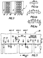
- the rotor 1 which has at its periphery permanent magnets 2, further includes a number predetermined pole pieces 3 distributed regularly around the axis 4 of the rotor 1.
- the sheet magnetic 5 has six pole pieces 3 distributed regularly around axis 4, two pole pieces 3 adjacent being spaced angularly from each other 60 °.
- Each sheet 5 has a central opening 5a for the passage of a tree not shown.
- the pole pieces 3 protrude radially outwardly relative to the peripheral edge 6 of the sheet 5.
- the edge device 6 is made up of three segments 7 which are tangents to the same circumference and which are adapted to serve as the base for a respective permanent magnet 2, such as shown schematically in Figures 2 and 2a on which we have represented magnets of parallelepiped shape.
- At least one permanent magnet 2 may have various forms, for example a form of tile, whose interior radius is then substantially equal to the radius of the edge 6 which is then circular.
- the magnets permanent 2 have a determined thickness. They are preferably radially magnetized, but can be axially magnetized that is to say in the direction of their axis, if the number of poles is large.
- Magnets 2 axially or radially magnetized. Magnets 2 inserted between the two adjacent pole pieces 3 located at the right of figure 3 all have their N pole on their face exposed exterior, and their S pole on their surface in contact with their seat 7. The magnets inserted between the pole pieces from the left side of the figure, from the other side of the center pole piece, are at otherwise magnetized in the opposite direction.
- Each substantially radial wall 8 of a magnet 2 adjacent to the corresponding substantially radial wall 9 of a pole piece 3 is, according to the invention, separated from this substantially radial wall 9 from a distance predetermined 10 which will be defined later.
- the predetermined distance 10 is fixed by a shoulder 11 extending in substantially direction tangential to the foot of the substantially radial wall 9 of the pole piece 3 and forming a stop for the magnet permanent 2 adjacent.
- the space provided between a wall substantially radial 9 of a pole piece 3 and the wall substantially corresponding adjacent radial 8 of a permanent magnet 2 is, in the embodiment shown in FIGS. 1 to 3, occupied by air.
- this space may be at less partially filled with a material element non-magnetic.
- This non-magnetic material can be glue or varnish, as shown in diagram 12 on the right of Figure 2, to improve the attachment of the magnets 2 on rotor 1.
- Element 13 of non-magnetic material shown in the left part of figure 2a presents a form tubular extending axially along the workpiece polar 3, and is adapted to be traversed by a fluid of cooling.
- Element 14 of non-magnetic material shown in the right part of figure 2a constitutes a part guide for guiding the adjacent magnet 2 when positioning the latter on the rotor 1. It is therefore attached to the side wall 9 of the pole piece 3 and has a surface 15 opposite the wall 9 which is inclined to guide magnet 2 to the edge of the shoulder 11 towards its seat 7.
- the element 13 described above could also have a substantially wall inclined such as wall 15 to assist in positioning of the magnets.
- Permanent magnets 2 are strong magnets energy density. They are preferably made of a material type with strong remanent induction Br and with field coercive Hc moderate at operating temperature expected, around 130 ° C in particular, for example in Nd Fe B alloy.
- the permanent magnets 2 have a thickness relatively small, for example between 4 and 8 mm, preferably between 4.5 and 5.5 mm, for magnets in Nd Fe B alloy.
- the predetermined distance 10 is substantially equal to the thickness of the magnets 2, and can be understood between 4 and 8 mm approximately. This effectively protects magnets 2 against the risk of demagnetistion by the field fringe which is present outside the walls side 9 of pole pieces 3.
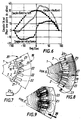
- the rotor described above is designed to equip a synchronous electric machine, shown schematically in 20 at the Figure 7, suitable for operating at constant power on a wide range of speeds from basic speed to a maximum speed of at least about three times this basic speed.
- This synchronous machine has a rotor 1 carrying permanent magnets 2 at its periphery, a stator 19 constituting a polyphase armature and having on its inner peripheral surface 18 of the teeth 21 delimiting notches 22 in which are wound coils shown diagrammatically at 23 in FIG.
- dimmer means 24 are known in themselves and need not be described in detail here. They obviously include a sensor (not shown) of position of the rotor which delivers an essential signal for voltage and current setting as well as the aforementioned angular offset.
- this maximum voltage is the maximum voltage that can deliver the battery to this vehicle.
- the machine synchronous electric device according to the invention must be able to operate at constant power over a wide range of speeds from basic speed to a speed maximum equal to at least about three times this speed basic.
- Figure 5 shows the classic representation of operating conditions of such a machine with the d axis of a magnet and the q axis between two magnets adjacent.
- the electrical angular offset of the q axis by relative to the axis d is 90 ° in the direction of the arrow 25 according to which the rotor 1 rotates relative to the armature polyphase of the stator 19.
- the diagram presented corresponds to the case of a three-phase armature consisting of one turn per pole and by phase, phase A serving as the reference phase.
- phase A serving as the reference phase.
- the flux ⁇ 0 of the magnets is angularly offset by an angle ⁇ + ⁇ / 2 relative to the flux ⁇ i of the polyphase armature.
- the machine can provide sound maximum torque.
- This regime corresponds to a setting angle ⁇ relatively small (the value of ⁇ depends on the point operating parameters and parameters ⁇ 0, Lq, Ld) generally between 0 and 45 °.
- the flux ⁇ o produced by the permanent magnets is weaker than we can get with other known rotor structures to permanent magnets.
- the resulting torque is the sum of the interaction torque relative to the flux of the magnets and the reluctance torque consecutive to the variation of permeance between the axes d and q. So, below the basic speed, the torque maximum will be obtained for an angle ⁇ generally between 15 and 45 ° electrical). In addition, when the current is fixed, the torque varies little in this range of variation of ⁇ , 30 ° electric. This finding will have important repercussions for the choice of position sensor required to control the machine (especially in the low speed area) because it sensor may have a relatively resolution weak compatible with coding technologies little expensive.
- Reluctance torque representing 20% to 30% of the resulting torque (for a speed lower than the basic speed, and depending on the design selected)
- the mass torque / ampere ratio will be equivalent to that of best servo motors fitted with magnets mounted in surface, but with a volume of magnets reduced by 20 to 30% compared to these.
- the Applicant has made numerous calculations and simulations to be able to determine the main geometric parameters of the synchronous magnet machine permanent 2 inserted between pole pieces 3 of the rotor 1 according to the present invention.
- a first parameter is the polar opening relative, ⁇ , shown in Figure 1, magnets 2 located between two adjacent pole pieces 3, and expressed as the quotient, less than 1, of the polar opening ⁇ . ⁇ / p of the magnets through the opening ⁇ / p polar of the rotor.
- the polar opening of the magnets must not exceed 0.65. Indeed, when ⁇ exceeds this value, the torque no longer increases.
- the magnets are not attached to the pole piece. Indeed, the flow of the polyphase armature is essentially channeled by this part, which ensures thus effective protection to magnets. However, a small part of this flow engages in the pole piece by the side faces 9 thereof. This requires reserve a space corresponding to the distance predetermined between a magnet 2 and the pole piece 3 adjacent.
- ⁇ is advantageously between 0.45 and 0.55, and is preferably equal to approximately 0.5, in order to obtain an optimum compromise between the performance and the cost of the synchronous motor.
- each part polar 3 corresponds to an opening relative polar ⁇ which is advantageously between 0.20 and 0.35 to obtain the aforementioned optimization, the rest of the polar opening being occupied by predetermined distances between magnet and pole piece adjacent to each other.
- the thickness of the magnets enabling the torque to be obtained maximum is close to 7.5 mm.
- the thickness of the magnets at 5.0 mm we obtain almost 95% of torque and resistance to demagnetization is assured (the field value in the magnets for the most severe load operating conditions remains significantly below the limit of demagnetization of the material, i.e. around 700 k A / m at 140 ° for an Nd Fe B alloy.
- Figure 8 shows the field lines obtained when the flux of the polyphase armature is produced by two turns 23 passing through notches located at both ends of the represented sector of the stator. This flow is directed in the direction of arrow 27 and is located in the q axis between two adjacent magnets, in the axis of the pole piece.
- FIG. 9 shows the field lines obtained when the flux is produced by two turns 23 located to the right of the pole piece. This flow is directed in the direction of arrow 28 and is located in the axis d of a magnet.
- the plaintiff has thus defined as follows the characteristics of a synchronous magnet motor permanent inserted between pole pieces on the rotor and having a maximum power of 27 KW.
- the magnets chosen are of the Nd Fe B type. They are for example of the type known under the name UGISTAB 26 XU (registered trademark) and manufactured by the company UGIMAG, this type having been chosen for its ability to withstand high temperatures to the detriment of certain magnetic characteristics.
Landscapes
- Engineering & Computer Science (AREA)
- Power Engineering (AREA)
- Permanent Field Magnets Of Synchronous Machinery (AREA)
- Synchronous Machinery (AREA)
- Permanent Magnet Type Synchronous Machine (AREA)
Description
- la figure 1 est une vue schématique en élévation d'une tôle magnétique découpée adaptée à former un rotor selon un mode de réalisation de l'invention ;
- la figure 2 est une vue agrandie d'un détail de la figure 1 sur laquelle on a représenté des aimants permanents ;
- la figure 2a est une vue semblable à la figure 2 représentant des variantes de réalisation du rotor selon l'invention ;
- la figure 3 est une vue schématique partielle de dessus d'un rotor correspondant au mode de réalisation des figures 1 et 2, avec les deux sens possibles de magnétisation des aimants ;
- les figures 4a, 4b, 4c sont des schémas représentant respectivement, en élévation, un aimant parallèlépipèdique aimanté en direction axiale, un aimant en forme de tuile aimanté en direction axiale et un aimant en forme de tuile aimanté en direction radiale ;
- la figure 5 est un schéma représentant les flux respectifs des aimants permanents du rotor et de l'armature polyphasée du stator et le décalage angulaire entre ces deux flux dans la représentation classique en axes d et q ;
- la figure 6 est un diagramme représentant les composantes du couple électromagnétique en fonction du décalage angulaire électrique du flux des aimants par rapport à celui de l'armature polyphasée ;
- la figure 7 est une vue partielle schématique représentant un secteur du rotor et du stator ;
- la figure 8 est une vue semblable à la figure 7 représentant les lignes de flux dans le cas où le flux de l'armature polyphasée est dirigé selon l'axe q ;
- la figure 9 est une vue semblable à la figure 7 représentant les lignes de flux dans le cas où le flux de l'armature polyphasée est dirigé selon l'axe d.
- le flux à vide ϕ 0 produit par les aimants ;
- le flux ϕ i produit par l'armature polyphasée du stator ;
- le décalage angulaire γ + π/2 du flux ϕ 0 des aimants par rapport au flux ϕ i de l'armature polyphasée.

- ϕ 0 = flux par pôle et par phase produit par les aimants à vide ;
- Lq (iq) = inductance dans l'axe q par pôle et par phase ;
- Ld (id) = inductance dans l'axe d par pôle et par phase ;
- ϕ d = Ld(id).id = Ld (id).i.sin γ
- ϕ q = Lq(iq).iq = Lq (iq).i.cos γ
- p étant le nombre de paires de pôles au rotor.
- le premier terme correspond au couple généré par les aimants seuls lorsque l'armature polyphasée est alimentée. Cette composante du couple est proportionnelle au flux des aimants et au courant. Elle est maximale pour γ =o, c'est à dire lorsque les vecteurs représentant les flux ϕ 0 et ϕ i sont en quadrature, et décroít lorsque γ varie de 0 à 90°.
- le second terme correspond à un couple de réluctance lié à la variation de perméance "vue" par l'armature polyphasée. Cette composante est proportionnelle à la variation d'inductance entre les positions q et d, et varie comme le carré de l'intensité. Le couple de réluctance s'ajoute à celui produit par les aimants lorsque Lq>Ld. Il est maximal pour γ = π/4.
| Puissance maximale | 27 KW |
| Tension batterie | 160 V |
| vitesse de base | 2250 min-1 |
| vitesse maximale | 9000 min-1 |
| courant efficace à puissance maximale | |
| - à base vitesse | 145 A |
| - à vitesse max | 120 A |
| Rendement moteur seul à puissance maximale | |
| - à vitesse basse | 0,92 |
| - à vitesse max | 0,88 |
| ROTOR : aimants | UGISTAB 26xU |
| diamètre extérieur tôlerie | 220 mm |
| longueur axiale fer | 110 mm |
| nombre de pôles | 6 |
| masse moto-réducteur diff. | 68 kg |
Claims (14)
- Machine électrique synchrone (20) à aimants permanents (2), adaptée à fonctionner à puissance constante sur une large plage de vitesses allant de la vitesse de base à une vitesse maximale égale à trois fois environ au moins cette vitesse de base, cette machine comportant un rotor (1) portant à sa périphérie (17) des aimants permanents (2), un stator (19) constituant une armature polyphasée et présentant sur sa surface périphérique intérieure (18) des dents (21) limitant des encoches (22) dans lesquelles sont bobinées des spires (23), et des moyens formant variateur (24) pour faire varier la tension et l'intensité du courant traversant les spires (23), ainsi que le décalage angulaire du flux magnétique des aimants (2) par rapport au flux de l'armature polyphasée du stator (19), le rotor (2) comportant un nombre prédéterminé de pièces polaires (3) et entre deux pièces polaires (3) adjacentes au moins un aimant permanent (2) d'épaisseur prédéterminée et aimanté radialement ou axialement, chaque paroi sensiblement radiale (8) d'un aimant (2) adjacente à la paroi sensiblement radiale(9) correspondante d'une pièce polaire (3) étant écartée de cette paroi sensiblement radiale (9) d'une distance (10) caractérisée en ce que ladite distance (10) est prédéterminée de façon à empêcher tout risque de démagnétisation de l'aimant (2) en présence d'un courant maximum susceptible de traverser la machine, notamment en cas de mise en court-circuit de cette dernière.
- Machine électrique synchrone selon la revendication 1, caractérisée en ce qu'elle constitue un moteur de traction de véhicule automobile électrique alimenté par une batterie d'accumulateurs.
- Rotor (1) à aimants permanents (2), caractérisé en ce qu'il est adapté à équiper une machine électrique synchrone selon la revendication 1 ou 2.
- Rotor selon la revendication 3, caractérisé en ce que la distance (10) prédéterminée est fixée par un épaulement (11) s'étendant en direction sensiblement tangentielle au pied de la paroi sensiblement radiale (9) de la pièce polaire (3) et formant butée pour l'aimant adjacent (2).
- Rotor selon la revendication 3 ou 4, caractérisé en ce que l'espace ménagé entre une paroi sensiblement radiale (9) d'une pièce polaire (3) et la paroi sensiblement radiale (8) adjacente correspondante d'un aimant (2) est au moins partiellement rempli d'un élément en matériau amagnétique.
- Rotor selon la revendication 5, caractérisé en ce que le matériau amagnétique est de la colle ou du vernis (12).
- Rotor selon la revendication 5, caractérisé en ce que l'élément (13) en matériau amagnétique présente une forme tubulaire s'étendant axialement le long de la pièce polaire (3) et est adapté à être traversé par un fluide de refroidissement.
- Rotor selon l'une quelconque des revendications 5 à 7, caractérisé en ce que l'élément (14) en matériau amagnétique constitue une pièce de guidage permettant le guidage de l'aimant (2) adjacent lors du positionnement dudit aimant (2) sur le rotor (1).
- Rotor selon l'une quelconque des revendications 3 à 8, caractérisé en ce que les aimants permanents (2) sont à forte densité d'énergie, notamment en un matériau du type à forte induction rémanente Br et à champ coercitif Hc modéré à la température de fonctionnement, notamment à 130°C environ, par exemple en alliage NdFeB.
- Rotor selon l'une quelconque des revendications 3 à 9, caractérisé en ce que les aimants permanents (2) présentent une épaisseur relativement faible, comprise entre 4 et 8 mm, de préférence entre 4,5 et 5,5 mm, pour des aimants en alliage NdFeB.
- Rotor selon l'une quelconque des revendications 3 à 10, caractérisé en ce que la distance (10) prédéterminée est sensiblement égale à l'épaisseur des aimants (2).
- Rotor selon l'une quelconque des revendications 3 à 11, caractérisé en ce que l'ouverture polaire relative des aimants est comprise entre 0,45 et 0,55 environ, et est notamment sensiblement égale à 0,5.
- Rotor selon l'une quelconque des revendications 3 à 12, caractérisé en ce que l'ouverture polaire relative des pièces polaires est comprise entre 0,20 et 0,35 environ.
- Rotor selon l'une quelconque des revendications 3 à 13, caractérisé en ce que les aimants (2) situés entre deux pièces polaires (3) adjacentes ont tous le même sens d'aimantation radial ou axial, et en ce que les sens d'aimantation des aimants (2) situés de part et d'autre d'une même pièce polaire (3) sont opposés.
Applications Claiming Priority (2)
| Application Number | Priority Date | Filing Date | Title |
|---|---|---|---|
| FR9515408 | 1995-12-22 | ||
| FR9515408A FR2742936B1 (fr) | 1995-12-22 | 1995-12-22 | Machine electrique synchrome a aimants permanents adaptee a fonctionner a puissance constante sur une large plage de vitesse |
Publications (2)
| Publication Number | Publication Date |
|---|---|
| EP0780954A1 EP0780954A1 (fr) | 1997-06-25 |
| EP0780954B1 true EP0780954B1 (fr) | 2000-08-16 |
Family
ID=9485895
Family Applications (1)
| Application Number | Title | Priority Date | Filing Date |
|---|---|---|---|
| EP96402797A Expired - Lifetime EP0780954B1 (fr) | 1995-12-22 | 1996-12-18 | Machine électrique synchrone à aimants permanents adaptée à fonctionner à puissance constante sur une large plage de vitesse |
Country Status (4)
| Country | Link |
|---|---|
| EP (1) | EP0780954B1 (fr) |
| JP (1) | JP2912277B2 (fr) |
| DE (1) | DE69609807T2 (fr) |
| FR (1) | FR2742936B1 (fr) |
Families Citing this family (14)
| Publication number | Priority date | Publication date | Assignee | Title |
|---|---|---|---|---|
| JPH10288054A (ja) * | 1997-02-13 | 1998-10-27 | Denso Corp | スロットル弁制御装置 |
| US6215207B1 (en) * | 1997-08-26 | 2001-04-10 | Denso Corporation | Torque motor having uniform torque output characteristics |
| SE516461C2 (sv) * | 2000-03-01 | 2002-01-15 | Abb Ab | Permanentmagnetrotor samt förfarande för tillverkning av en sådan |
| GB2370320A (en) | 2000-12-21 | 2002-06-26 | Ingersoll Rand Europ Sales Ltd | Compressor and driving motor assembly |
| DE102004042927A1 (de) * | 2004-09-02 | 2006-03-09 | Heinz Leiber | Läufer für eine elektrische Maschine |
| DE102005045347A1 (de) | 2005-09-22 | 2007-04-05 | Siemens Ag | Zahnmodul für Primärteile von permanentmagneterregten Synchronmotoren |
| JP4312778B2 (ja) | 2006-08-09 | 2009-08-12 | 三菱電機株式会社 | 磁石発電機の製造方法 |
| EP2301140B1 (fr) * | 2008-07-22 | 2018-09-05 | Multibrid GmbH | Machine synchrone à aimants permanents |
| EP2395630A1 (fr) * | 2010-06-10 | 2011-12-14 | Siemens Aktiengesellschaft | Machine à aimant permanent, en particulier un générateur pour éolienne |
| US10199895B2 (en) | 2013-04-09 | 2019-02-05 | Mistubishi Electric Corporation | Permanent magnet type motor and electric power steering apparatus |
| WO2015122015A1 (fr) * | 2014-02-17 | 2015-08-20 | 三菱電機株式会社 | Moteur à aimant permanent |
| TWI665852B (zh) | 2018-06-26 | 2019-07-11 | 魅克司股份有限公司 | 磁性轉盤 |
| JP7079746B2 (ja) * | 2019-03-08 | 2022-06-02 | 本田技研工業株式会社 | 回転電機のロータ及びその製造方法 |
| WO2023236032A1 (fr) * | 2022-06-07 | 2023-12-14 | 汉宇集团股份有限公司 | Moteur synchrone à aimant permanent et son rotor |
Family Cites Families (5)
| Publication number | Priority date | Publication date | Assignee | Title |
|---|---|---|---|---|
| GB1359548A (en) * | 1971-12-09 | 1974-07-10 | Univ Southampton | Permanent magnetic rotor for synchronous electric machines |
| JPS57186965A (en) * | 1981-05-11 | 1982-11-17 | Hitachi Ltd | Rotor for permanent-magnet type synchronous motor |
| JPS60121949A (ja) | 1983-12-05 | 1985-06-29 | Fanuc Ltd | 永久磁石型同期電動機の回転子 |
| FR2652688B2 (fr) | 1989-01-11 | 1991-10-18 | Alsthom Gec | Commande pour la marche a puissance constante d'un moto-variateur synchrone. |
| GB9112059D0 (en) * | 1991-06-05 | 1991-07-24 | Jestar Ltd | Electrical machines |
-
1995
- 1995-12-22 FR FR9515408A patent/FR2742936B1/fr not_active Expired - Fee Related
-
1996
- 1996-12-18 DE DE69609807T patent/DE69609807T2/de not_active Expired - Lifetime
- 1996-12-18 EP EP96402797A patent/EP0780954B1/fr not_active Expired - Lifetime
- 1996-12-24 JP JP8344246A patent/JP2912277B2/ja not_active Expired - Fee Related
Also Published As
| Publication number | Publication date |
|---|---|
| FR2742936B1 (fr) | 1998-02-13 |
| FR2742936A1 (fr) | 1997-06-27 |
| JP2912277B2 (ja) | 1999-06-28 |
| EP0780954A1 (fr) | 1997-06-25 |
| DE69609807T2 (de) | 2001-03-01 |
| DE69609807D1 (de) | 2000-09-21 |
| JPH09298864A (ja) | 1997-11-18 |
Similar Documents
| Publication | Publication Date | Title |
|---|---|---|
| EP0780954B1 (fr) | Machine électrique synchrone à aimants permanents adaptée à fonctionner à puissance constante sur une large plage de vitesse | |
| EP1362407B1 (fr) | Machine tournante perfectionnee pour vehicule automobile | |
| FR2960355B1 (fr) | Machine electrique rotative a resistance magnetique amelioree | |
| EP0909010B1 (fr) | Machine électrique à commutation de flux, et notamment alternateur de véhicule automobile | |
| EP0913914B1 (fr) | Machine électrique à double excitation, et notamment alternateur de véhicule automobile | |
| WO2009153511A2 (fr) | Rotor a aimants permanents et machine tournante comportante un tel rotor | |
| FR3019948A1 (fr) | Rotor de machine electrique tournante. | |
| EP3104501B1 (fr) | Rotor pour machine electrique tournante | |
| WO2015155730A2 (fr) | Stator de machine electrique tournante | |
| FR2844112A1 (fr) | Moteur synchrone a aimant permanent | |
| EP3602755A1 (fr) | Machine électrique tournante à configuration optimisée | |
| EP2599197B1 (fr) | Machine electrique tournante synchrone avec rotor a double excitation | |
| EP2209192A1 (fr) | Machine électrique tournante, en particulier pour un démarreur de véhicule automobile | |
| WO2012042135A1 (fr) | Machine electrique tournante synchrone avec rotor a double excitation | |
| EP2599196B1 (fr) | Machine electrique tournante synchrone avec rotor a double excitation | |
| CH715403A2 (fr) | Enroulement pour machines électriques. | |
| FR2641139A1 (fr) | ||
| EP2599198B1 (fr) | Machine electrique tournante synchrone avec rotor a double excitation | |
| FR2831345A1 (fr) | Machine electrique a defluxage mecanique | |
| EP2005554A1 (fr) | Rotor de machine electrique tournante comportant des gorges pour aimants | |
| FR3086118A1 (fr) | Machine electrique tournante munie d'un rotor a masse reduite | |
| FR2809240A1 (fr) | Machine electrique homopolaire et procede de fabrication d'une telle machine | |
| WO2021099023A1 (fr) | Rotor pour machine électrique tournante | |
| FR3084793A1 (fr) | Machine electrique tournante munie d'un bobinage a configuration optimisee | |
| WO2021064315A1 (fr) | Rotor de machine electrique tournante |
Legal Events
| Date | Code | Title | Description |
|---|---|---|---|
| PUAI | Public reference made under article 153(3) epc to a published international application that has entered the european phase |
Free format text: ORIGINAL CODE: 0009012 |
|
| AK | Designated contracting states |
Kind code of ref document: A1 Designated state(s): BE DE ES GB IT LU NL SE |
|
| 17P | Request for examination filed |
Effective date: 19970701 |
|
| GRAG | Despatch of communication of intention to grant |
Free format text: ORIGINAL CODE: EPIDOS AGRA |
|
| 17Q | First examination report despatched |
Effective date: 19990201 |
|
| GRAG | Despatch of communication of intention to grant |
Free format text: ORIGINAL CODE: EPIDOS AGRA |
|
| GRAH | Despatch of communication of intention to grant a patent |
Free format text: ORIGINAL CODE: EPIDOS IGRA |
|
| GRAH | Despatch of communication of intention to grant a patent |
Free format text: ORIGINAL CODE: EPIDOS IGRA |
|
| GRAA | (expected) grant |
Free format text: ORIGINAL CODE: 0009210 |
|
| AK | Designated contracting states |
Kind code of ref document: B1 Designated state(s): BE DE ES GB IT LU NL SE |
|
| PG25 | Lapsed in a contracting state [announced via postgrant information from national office to epo] |
Ref country code: NL Free format text: LAPSE BECAUSE OF FAILURE TO SUBMIT A TRANSLATION OF THE DESCRIPTION OR TO PAY THE FEE WITHIN THE PRESCRIBED TIME-LIMIT Effective date: 20000816 Ref country code: IT Free format text: LAPSE BECAUSE OF FAILURE TO SUBMIT A TRANSLATION OF THE DESCRIPTION OR TO PAY THE FEE WITHIN THE PRE;WARNING: LAPSES OF ITALIAN PATENTS WITH EFFECTIVE DATE BEFORE 2007 MAY HAVE OCCURRED AT ANY TIME BEFORE 2007. THE CORRECT EFFECTIVE DATE MAY BE DIFFERENT FROM THE ONE RECORDED.SCRIBED TIME-LIMIT Effective date: 20000816 Ref country code: GB Free format text: LAPSE BECAUSE OF FAILURE TO SUBMIT A TRANSLATION OF THE DESCRIPTION OR TO PAY THE FEE WITHIN THE PRESCRIBED TIME-LIMIT Effective date: 20000816 Ref country code: ES Free format text: THE PATENT HAS BEEN ANNULLED BY A DECISION OF A NATIONAL AUTHORITY Effective date: 20000816 |
|
| REF | Corresponds to: |
Ref document number: 69609807 Country of ref document: DE Date of ref document: 20000921 |
|
| PG25 | Lapsed in a contracting state [announced via postgrant information from national office to epo] |
Ref country code: SE Free format text: LAPSE BECAUSE OF FAILURE TO SUBMIT A TRANSLATION OF THE DESCRIPTION OR TO PAY THE FEE WITHIN THE PRESCRIBED TIME-LIMIT Effective date: 20001116 |
|
| PG25 | Lapsed in a contracting state [announced via postgrant information from national office to epo] |
Ref country code: LU Free format text: LAPSE BECAUSE OF NON-PAYMENT OF DUE FEES Effective date: 20001218 |
|
| PG25 | Lapsed in a contracting state [announced via postgrant information from national office to epo] |
Ref country code: BE Free format text: LAPSE BECAUSE OF NON-PAYMENT OF DUE FEES Effective date: 20001231 |
|
| GBV | Gb: ep patent (uk) treated as always having been void in accordance with gb section 77(7)/1977 [no translation filed] |
Effective date: 20000816 |
|
| PLBE | No opposition filed within time limit |
Free format text: ORIGINAL CODE: 0009261 |
|
| STAA | Information on the status of an ep patent application or granted ep patent |
Free format text: STATUS: NO OPPOSITION FILED WITHIN TIME LIMIT |
|
| BERE | Be: lapsed |
Owner name: S.A. MOTEURS LEROY-SOMER Effective date: 20001231 |
|
| 26N | No opposition filed | ||
| PGFP | Annual fee paid to national office [announced via postgrant information from national office to epo] |
Ref country code: DE Payment date: 20101222 Year of fee payment: 15 |
|
| REG | Reference to a national code |
Ref country code: DE Ref legal event code: R119 Ref document number: 69609807 Country of ref document: DE Effective date: 20120703 |
|
| PG25 | Lapsed in a contracting state [announced via postgrant information from national office to epo] |
Ref country code: DE Free format text: LAPSE BECAUSE OF NON-PAYMENT OF DUE FEES Effective date: 20120703 |