EP0780305B1 - Vorrichtung und Verfahren zum Schutz von elektronischen Einheiten in einem Satelliten gegen elektrische Störungen - Google Patents
Vorrichtung und Verfahren zum Schutz von elektronischen Einheiten in einem Satelliten gegen elektrische Störungen Download PDFInfo
- Publication number
- EP0780305B1 EP0780305B1 EP96120415A EP96120415A EP0780305B1 EP 0780305 B1 EP0780305 B1 EP 0780305B1 EP 96120415 A EP96120415 A EP 96120415A EP 96120415 A EP96120415 A EP 96120415A EP 0780305 B1 EP0780305 B1 EP 0780305B1
- Authority
- EP
- European Patent Office
- Prior art keywords
- electronic components
- components
- satellite
- faraday cage
- electronic
- Prior art date
- Legal status (The legal status is an assumption and is not a legal conclusion. Google has not performed a legal analysis and makes no representation as to the accuracy of the status listed.)
- Expired - Lifetime
Links
Images

Classifications
-
- B—PERFORMING OPERATIONS; TRANSPORTING
- B64—AIRCRAFT; AVIATION; COSMONAUTICS
- B64G—COSMONAUTICS; VEHICLES OR EQUIPMENT THEREFOR
- B64G1/00—Cosmonautic vehicles
- B64G1/22—Parts of, or equipment specially adapted for fitting in or to, cosmonautic vehicles
-
- B—PERFORMING OPERATIONS; TRANSPORTING
- B64—AIRCRAFT; AVIATION; COSMONAUTICS
- B64G—COSMONAUTICS; VEHICLES OR EQUIPMENT THEREFOR
- B64G1/00—Cosmonautic vehicles
- B64G1/22—Parts of, or equipment specially adapted for fitting in or to, cosmonautic vehicles
- B64G1/52—Protection, safety or emergency devices; Survival aids
- B64G1/54—Protection against radiation
Definitions
- the present invention relates to a method for electrically isolating electronic components within a platform module of a satellite from electrical disturbance, and to a corresponding satellite platform module.
- a satellite is a type of spacecraft that orbits either the earth or another body of the solar system.
- Information satellites transmit signals related to atmospheric and meteorological data, infrared, ultraviolet, gamma and X-ray studies of celestial objects, and surveys of the earth's shape, surface, and resources.
- Communications satellites receive radio frequency signals from earth by means of highly directional aerials and return them to another earth location for purposes such as long-distance telephony and TV broadcasting.
- a satellite typically includes a payload module and a platform module.
- the payload is the communications equipment necessary to perform the mission.
- the platform typically includes the following subsystems: (1) power; (2) attitude and control; (3) propulsion; (4) on-board telemetry tracking and command (TTC); (5) thermal control; and (6) structure. These subsystems play a vital role throughout the satellite's operational life.
- the structure of the satellite platform module includes a configuration of rigid panels capable of withstanding intense mechanical stresses imposed during various phases of the mission.
- the panels are typically manufactured from strong lightweight materials such as aluminum honeycomb combined with aluminum or carbon fiber face sheets. Panel weight is further minimized by providing holes through the solid material.
- An electrical shield called a faraday cage is commonly used to protect the platform electronic units (e.g. power distribution unit and power controller unit) from unwanted electrical disturbances such as electrostatic discharge.
- platform electronic units e.g. power distribution unit and power controller unit
- propulsion components e.g. propulsion tanks and thrusters
- the faraday cage must surround the entire platform.
- One method of accomplishing this is to wrap the platform in thermal blankets containing layers of metallized material. The blankets are then connected together by blanket ground wires to form a faraday cage around the platform.
- An alternative approach is to incorporate within the platform panels a material such that, when the panels are connected, a faraday cage is created.
- US 4,599,680 discloses a packaging arrangement for a spacecraft computer.
- the packaging comprises a base plate which is fixed to an adapter bracket and, further, via a metal gasket to a cover.
- the cover and the base plate are made of electrical and heat conductive material, such as aluminum.
- the packaging is therefore resistant to electromagnetically noisy environments.
- the power for running the power supply is received through a power connector and is immediately filtered through a filter element to prevent unwanted spikes or electromagnetic interference.
- the filter element prevents any external interference from coming into the computer over the power lines.
- EP 0 484 853 A1 discloses a method and a device for protecting electronic components against radiation. In order to reduce the weight of the shielding measurements, this reference suggests to place the shielding material in dependence of the angle of incidence of the radiation.
- the object is achieved by a method comprising the steps of :
- a platform module of a satellite including propulsion components and electronic components, with said electronic components being platform electronic units of the satellite, and further including a device for electrically isolating said electronic components from electrical disturbance, said device comprising a structure forming a faraday cage, wherein said electronic components are contained within said structure, and wherein the propulsion components are located outside the structure, whereby the electronic units and the propulsion components are separated.
- the present invention provides a device and method which can be implemented in the structure subsystem of a satellite. Specifically, the device and method of the present invention are capable of protecting a satellite from unwanted electrical disturbance without increasing the satellite's weight.
- the electronic units and propulsion components are separated. Further, the electronic units are grouped closely together to minimize the size of the structure needed to house them. Preferably, there are two sets of electronics units located on the satellite.
- the structure that houses the electronic units is preferably made from solid panels containing a sufficient amount of aluminum to create a faraday cage around the units. The faraday cage protects the units from electrical disturbances such as the electrostatic discharge formed on the satellite during its mission.
- the device and method of the present invention provides several advantages to the structural design of a satellite.
- the modular placement of electronic units and propulsion components separates critical electronics from propulsion components, thereby allowing a structure with solid panels to house the electronic components without significantly increasing the satellite's weight.
- the modular placement also allows the faraday cage to be broken into discrete structures connected via a cluster of wires called a harness. Because the propulsion components are located outside the faraday cage, and the electronic units are centrally located, the number of wire connections that penetrate the cage are minimized. Thus a faraday cage constructed according to the present invention is penetrated only where the harness penetrates the two structures.
- the harness is covered by a braided metal in the form of a tubular mesh that wraps 360 degrees around the harness and connects to the two structures via connectors.
- two harnesses are used and are covered by a shielded cable tray made from an aluminum material to provide additional protection from unwanted electrical disturbances.
- modular placement of electronic units allows a novel method of shielding the wires that connect the electronics units to components located outside of the faraday cage.
- wires from the electronics units are connected to a first side of a filter assembly which is located on a panel of the electronic unit housing.
- Wires connected to the second side of the filter assembly are routed to the components located outside the faraday cage.
- the filter assembly electronically filters undesired signals originating from components outside the faraday cage before routing the desired signals to electronics components inside the faraday cage.
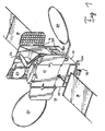
- a spacecraft or satellite 10 capable of utilizing the present invention is shown in Figure 1.
- the satellite 10 has a spacecraft body 12 which includes a lower bus module or platform 14 and an upper payload module 16. Attached to the aft end of the lower bus module 14 are a plurality of engines. These engines include a centrally positioned liquid orbital thruster (not shown), four chemical propulsion engines 24 located at the corners of the bus module 14 and two pairs of xenon ion propulsion engines 26 (one pair shown).
- Lower bus module 14 contains fuel tanks (not shown) and various power and control modules that operate the engines and power the payload module 16.
- Bus module 14 further includes a pair of solar panels 18 that convert sunlight into electricity. The electricity is sent to batteries (not shown) located on the bus module 14.
- Bus module 14 also has a pair of antennae 20, which receive signals from an earth ground station.
- the antennae 20 reflect the received signals into reflectors 22, which in turn, reflect the signals into receivers (not shown).
- the antennae 20 are used to control the satellite 10 and to send signals to the ground station.
- Payload module 16 is attached to the bus module 14 and contains a variety of electronic equipment which may contain a number of sensors (not shown).
- the electronic equipment processes information gathered by the sensors and sends the processed information back to the ground station via antennae 20.
- the gathered information may concern for example, communications, weather observation, and navigational information.
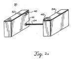
- FIG 2a illustrates a first preferred embodiment of the Faraday cage configuration 30 of the present invention.
- the configuration 30 preferably includes two shielded faraday structures 32, 34 which are located on the north panel 28 and south panel (not shown) of the bus module 14 of Figure 1.
- the shielded faraday structures 32, 34 house the electronic units on board the satellite.
- the panels of the structures 32, 34 are constructed of a honeycomb core adhesively affixed between two solid aluminum face sheets.
- the panels are connected to form a faraday cage around the electronic units using known RF sealing materials.
- the exact dimensions of the structures 32, 34 should be chosen according to the particular application.
- the structures 32, 34 are rectangular boxes.
- the faraday cages of the boxes 32, 34 are electrically connected via a bundle of wires or a harness (not shown) surrounded by a braided metal mesh 64.
- the braided metal mesh 64 is connected to the boxes 32, 34 via connectors 66 (only one shown) commonly known in the art.
- a suitable metal mesh 64 is mil-std space qualified commonly known in the art.
- the faraday cages of the boxes 32, 34 are electrically connected via two bundles of wires or harnesses (not shown) surrounded by shielded cable trays 36, 38.
- the shielded cable trays 36, 38 provide continuity of the faraday cage of structures 32, 34.
- FIG. 3a illustrates a perspective view of a filter assembly 40 which includes a box structure 46, an aluminum lid 42, and an RF gasket 44 commonly used in the art to ensure electrical conductivity.
- the box structure 46 includes two flanges 48 for mounting the assembly 40 to a panel of the faraday cage structure 32, 34.
- the panels of the box structure 46 are preferably made from aluminum.
- One panel 50 of the assembly 40 is configured to accept 66 pin circular input connectors 52 ( Figure 3b).
- Another panel (not shown) of the assembly 40 is configured to accept 66 pin circular output connectors 54 ( Figure 3b).
- the connectors 52, 54 are off-the-shelf devices commonly known in the art.
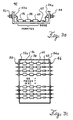
- FIGS. 3b and 3c illustrate further details of the filter assembly 40.
- the wire end of the input connector 52 which is represented by filter pin 52a, is coupled to a first end of a ferrite 56.
- the other end of the ferrite 56 is connected to the first end of a ferrite 58.
- the second end of the ferrite 58 is coupled to the first end of a ferrite 60.
- the second end of the ferrite 60 is coupled to the first end of a diode 62.
- the second end of the diode 62 is coupled to the wire end 54a of the output connector 54.
- the ferrites 56, 58, 60 and diode 62 are chosen according to mil-std specifications and should be approved for space applications. The particular size of ferrites and diode should be chosen according to the type and size of signals that are to be filtered.
- the components located outside the faraday cage structures 32, 34 are coupled to the pin ends of the 66 pin circular input connectors 52.
- the electronic units located inside the faraday cage structures 32, 34 are coupled to the pin ends of the 66 pin circular output connectors 54. Signals originating from components outside the faraday cage are electronically filtered through the ferrites 56, 58, 60 and diode 62 before reaching the electronic units inside the faraday cage structures 32, 34.
- the device and method of the present invention provide several advantages to the structural design of a satellite. Modular placement of units and propulsion components allows a structure with solid panels to be used to house the electronic units without significantly increasing the satellite's weight. Modular placement minimizes penetrations of the faraday cage, thereby eliminating damage to the electronic units. Modular placement also significantly decreases the probability of digital electronics equipment randomly changing states due to electrical disturbances. Connections between electronic units and components outside the faraday cage through filter assemblies eliminate the problems associated with individual connections such as bad wraps, bad grounds and forgotten grounds.
Landscapes
- Engineering & Computer Science (AREA)
- Health & Medical Sciences (AREA)
- General Health & Medical Sciences (AREA)
- Remote Sensing (AREA)
- Aviation & Aerospace Engineering (AREA)
- Toxicology (AREA)
- Critical Care (AREA)
- Emergency Medicine (AREA)
- Shielding Devices Or Components To Electric Or Magnetic Fields (AREA)
- Noise Elimination (AREA)
Claims (12)
- Plattformmodul eines Satelliten (10) mit Antriebskomponenten und elektronischen Komponenten, wobei die elektronischen Komponenten elektronische Einheiten der Plattform des Satelliten sind, und ferner mit einer Vorrichtung zur elektrischen Isolation der elektronischen Komponenten von elektrischen Störungen, wobei die Vorrichtung eine Struktur (32, 34) aufweist, die einen Faraday'schen Käfig ausbildet, wobei die elektronischen Komponenten innerhalb der Struktur (32, 34) enthalten sind, und wobei die Antriebskomponenten außerhalb der Struktur (32, 34) angeordnet sind, wodurch die elektronischen Einheiten und die Antriebskomponenten voneinander getrennt sind.
- Plattformmodul nach Anspruch 1, dadurch gekennzeichnet, dass die Vorrichtung aufweist:eine erste Struktur (32), die einen ersten Faraday'schen Käfig ausbildet,eine erste Vielzahl von elektronischen Komponenten, die innerhalb der ersten Struktur (32) angeordnet sind,eine zweite Struktur (34), die einen zweiten Faraday'schen Käfig ausbildet,eine zweite Vielzahl von elektronischen Komponenten, die innerhalb der zweiten Struktur (34) angeordnet sind, undeine Vielzahl von Leitungen (36, 38, 64), die eine bestimmte Anzahl der ersten elektronischen Komponenten mit einer bestimmten Anzahl der zweiten elektronischen Komponenten verbinden.
- Plattformmodul nach Anspruch 2, dadurch gekennzeichnet, dass die erste Struktur (32) und die zweite Struktur (34) Platten (50) aufweisen, die einen elektrischen Leiter beinhalten.
- Plattformmodul nach Anspruch 2 oder 3, dadurch gekennzeichnet, dass die Vielzahl von Leitungen (36, 38, 64) von einem geflochtenen Metallgitter (64) bedeckt sind.
- Plattformmodul nach einem der Ansprüche 1 bis 4, dadurch gekennzeichnet, dass die Vorrichtung ferner eine Filteranordnung (40) aufweist.
- Plattformmodul nach Anspruch 5, dadurch gekennzeichnet, dass die Filteranordnung (40) aufweist:eine Vielzahl von Ferriten (56, 58, 60), die in einer seriellen Art und Weise verbunden sind; undeine Diode (62), die seriell mit der Vielzahl von Ferriten (56, 58, 60) verbunden ist.
- Plattformmodul nach Anspruch 5 oder 6, dadurch gekennzeichnet, dass die Filteranordnung (40) ferner aufweist:eine Kastenstruktur (46) aus Aluminium, die eine Vielzahl von Platten (50) aufweist; undKonnektoren (52, 54), die auf den Platten (50) der Struktur (46) angeordnet sind, wobei die Ferrite (56, 58, 60) und die Diode (62) zwischen den Konnektoren (52, 54) angeordnet sind.
- Verfahren zum elektrischen Isolieren von elektronischen Komponenten innerhalb eines Plattformmoduls eines Satelliten (10) gegenüber elektrischen Störungen, wobei das Plattformmodul Antriebskomponenten und die elektronischen Komponenten beinhaltet, und wobei die elektronischen Komponenten elektronische Einheiten der Plattform des Satelliten sind, wobei das Verfahren die folgenden Schritte aufweist:Ausbilden einer Struktur (32, 34), die einen Faraday'schen Käfig erzeugt,Umhäusen der elektronischen Komponenten in der Struktur (32, 34), undAnordnen der Antriebskomponenten außerhalb der Struktur (32, 34), wodurch die elektronischen Einheiten und die Antriebskomponenten getrennt werden.
- Verfahren nach Anspruch 8, gekennzeichnet durch die Schritte:Ausbilden einer ersten Struktur (32), die einen ersten Faraday'schen Käfig erzeugt,Umhäusen einer ersten Vielzahl der elektronischen Komponenten in der ersten Struktur (32),Ausbilden einer zweiten Struktur (34), die einen zweiten Faraday'schen Käfig erzeugt,Umhäusen einer zweiten Vielzahl der elektronischen Komponenten in der zweiten Struktur (34), undVerbinden einer bestimmten Anzahl der ersten elektronischen Komponenten mit einer bestimmten Anzahl der zweiten elektronischen Komponenten.
- Verfahren nach Anspruch 9, dadurch gekennzeichnet, dass der Schritt des Verbindens mit einer Vielzahl von abgeschirmten Leitungen (36, 38, 64) ausgeführt wird.
- Verfahren nach Anspruch 9 oder 10, dadurch gekennzeichnet, dass es ferner ein Verbinden einer bestimmten Anzahl der Vielzahl von elektronischen Komponenten mit einer bestimmten Anzahl an Komponenten, die außerhalb der Strukturen (32, 34) angeordnet sind, beinhaltet.
- Verfahren nach Anspruch 11, dadurch gekennzeichnet, dass der Schritt des Verbindens aufweist:Verbinden einer Vielzahl von Ferriten (56, 58, 60) in einer seriellen Art und Weise, wobei die Vielzahl ein erstes Ende und ein zweites Ende besitzt, wobei das erste Ende der Vielzahl mit einer Leitungsseite (52a) eines eingangseitigen Konnektors (52) verbunden wird,Verbinden einer Diode (62) zwischen dem zweiten Ende der Vielzahl von Ferriten und einer Leitungsseite (54a) eines ausgangsseitigen Konnektors (54),Verbinden der bestimmten Anzahl an außerhalb der Strukturen (32, 34) angeordneten Komponenten mit einer Stiftseite des eingangseitigen Konnektors (52), undVerbinden der bestimmten Anzahl der Vielzahl von elektronischen Komponenten mit einer Stiftseite des ausgangsseitigen Konnektors (54).
Applications Claiming Priority (2)
| Application Number | Priority Date | Filing Date | Title |
|---|---|---|---|
| US577438 | 1995-12-22 | ||
| US08/577,438 US5717576A (en) | 1995-12-22 | 1995-12-22 | Device and method for protecting electronic units in a satellite from electrical disturbance |
Publications (3)
| Publication Number | Publication Date |
|---|---|
| EP0780305A2 EP0780305A2 (de) | 1997-06-25 |
| EP0780305A3 EP0780305A3 (de) | 1998-07-01 |
| EP0780305B1 true EP0780305B1 (de) | 2003-12-10 |
Family
ID=24308733
Family Applications (1)
| Application Number | Title | Priority Date | Filing Date |
|---|---|---|---|
| EP96120415A Expired - Lifetime EP0780305B1 (de) | 1995-12-22 | 1996-12-18 | Vorrichtung und Verfahren zum Schutz von elektronischen Einheiten in einem Satelliten gegen elektrische Störungen |
Country Status (3)
| Country | Link |
|---|---|
| US (1) | US5717576A (de) |
| EP (1) | EP0780305B1 (de) |
| DE (1) | DE69631024T2 (de) |
Families Citing this family (9)
| Publication number | Priority date | Publication date | Assignee | Title |
|---|---|---|---|---|
| SE9600183L (sv) * | 1996-01-18 | 1997-06-09 | Ericsson Telefon Ab L M | Skyddsanordning för elektromagnetisk koppling och elektrostatisk urladdning och användning därav |
| US6242691B1 (en) * | 1999-02-03 | 2001-06-05 | Lockheed Martin Corporation | Electronic packaging and method of packaging |
| US6399875B1 (en) | 1999-08-13 | 2002-06-04 | Ptmw, Inc. | Lightning protected housing structure |
| US6515221B1 (en) * | 2000-08-01 | 2003-02-04 | Honeywell International Inc. | Modular reaction wheel assembly to shield electronics on a satellite |
| US6717047B2 (en) * | 2001-08-27 | 2004-04-06 | Hewlett-Packard Development Company, L.P. | EMI enclosure having a flexible cable shield |
| US11510347B2 (en) | 2018-12-05 | 2022-11-22 | John Moroney | EMP-resistant satellite communications with signal regenerating system and method |
| US11824623B2 (en) | 2018-12-05 | 2023-11-21 | John Moroney | EMP-resistant satellite communications system and method |
| US11196481B2 (en) | 2018-12-05 | 2021-12-07 | John Moroney | EMP-resistant satellite communications system and method |
| US12438263B2 (en) | 2019-12-05 | 2025-10-07 | John Moroney | EMP-resistant telecommunications system and method with signal regenerating subsystem |
Family Cites Families (5)
| Publication number | Priority date | Publication date | Assignee | Title |
|---|---|---|---|---|
| US4599680A (en) * | 1983-09-26 | 1986-07-08 | Southwest Research Institute | Packaging arrangement for spacecraft computer |
| FR2668847B1 (fr) * | 1990-11-07 | 1994-06-03 | Alcatel Espace | Methode de protection de composants electroniques d'un circuit contre les radiations et dispositif utilisant cette methode. |
| JP2526820Y2 (ja) * | 1991-05-24 | 1997-02-26 | 北川工業株式会社 | 電磁波シールド用編物 |
| JPH0529152A (ja) * | 1991-07-20 | 1993-02-05 | Sony Corp | シールド部品 |
| US5223806A (en) * | 1991-08-23 | 1993-06-29 | Digital Equipment Corporation | Method and apparatus for reducing electromagnetic interference and emission associated with computer network interfaces |
-
1995
- 1995-12-22 US US08/577,438 patent/US5717576A/en not_active Expired - Lifetime
-
1996
- 1996-12-18 EP EP96120415A patent/EP0780305B1/de not_active Expired - Lifetime
- 1996-12-18 DE DE69631024T patent/DE69631024T2/de not_active Expired - Lifetime
Also Published As
| Publication number | Publication date |
|---|---|
| DE69631024D1 (de) | 2004-01-22 |
| DE69631024T2 (de) | 2004-08-19 |
| EP0780305A2 (de) | 1997-06-25 |
| US5717576A (en) | 1998-02-10 |
| EP0780305A3 (de) | 1998-07-01 |
Similar Documents
| Publication | Publication Date | Title |
|---|---|---|
| US5979833A (en) | Modular spacecraft architecture | |
| EP0780294A2 (de) | Unabhängiger, modularer Satellit-Subsystementwurf für Standard-Bus, Kommunikationsnutzlast mit veränderlichem Aufbau, und Aufträgen | |
| EP0394489B1 (de) | Antennennetz und stromversorgung dieses netzes | |
| US5961076A (en) | Modular spacecraft development process | |
| US11518548B2 (en) | Deployable spacecraft body | |
| US5717576A (en) | Device and method for protecting electronic units in a satellite from electrical disturbance | |
| CA2037008A1 (en) | Geostationary earth observation satellite incorporating liquid propellant apogee maneuver system and hollow antennas | |
| US20220127023A1 (en) | Spacecraft with universal test port | |
| US5931418A (en) | Functionally independent spacecraft module | |
| US5991138A (en) | Method and apparatus for protecting aircraft electronics from lightning | |
| US5244417A (en) | Backshell interface system | |
| CA2161249A1 (en) | Low profile backshell/wiring integration and interface system | |
| Credland et al. | The Cluster mission: ESA's spacefleet to the magnetosphere | |
| EP1305211B1 (de) | Modulare reaktionsradvorrichtung zur beschirmung der elektronik in einem satelliten | |
| US11848394B2 (en) | Photovoltaic module and flexible satellite solar generator | |
| Hausler et al. | The Ampte Irm Spacecraft | |
| Bose et al. | Harness Design of Electric Propulsion Systems | |
| Schaefer et al. | ASpacecraft Packaging | |
| Lakshminarayana et al. | Assessment and control of electromagnetic interference in CARTOSAT-1 spacecraft | |
| RU2825163C1 (ru) | Конструкция унифицированной космической платформы, ориентированной на автоматизированную сборку | |
| Kampinsky et al. | ATS-F Spacecraft: An EMC Challenge | |
| Bogorad et al. | Design approach and spacecraft EMI test methodology for high power communication spacecraft | |
| Rajesh et al. | EMI prediction and analysis for experimental payloads of advanced communication technology satellite—GSAT-4 | |
| Elkman et al. | EMI/EMC, lightning, radiation shielding design approach for the Dragon COTS spacecraft: Part I | |
| McKerchar | Electromagnetic Compatibility of High Density Wiring Installations by Design or Retrofit |
Legal Events
| Date | Code | Title | Description |
|---|---|---|---|
| PUAI | Public reference made under article 153(3) epc to a published international application that has entered the european phase |
Free format text: ORIGINAL CODE: 0009012 |
|
| AK | Designated contracting states |
Kind code of ref document: A2 Designated state(s): DE FR GB |
|
| PUAL | Search report despatched |
Free format text: ORIGINAL CODE: 0009013 |
|
| AK | Designated contracting states |
Kind code of ref document: A3 Designated state(s): DE FR GB |
|
| RAP1 | Party data changed (applicant data changed or rights of an application transferred) |
Owner name: HUGHES ELECTRONICS CORPORATION |
|
| 17P | Request for examination filed |
Effective date: 19981212 |
|
| 17Q | First examination report despatched |
Effective date: 20011030 |
|
| GRAH | Despatch of communication of intention to grant a patent |
Free format text: ORIGINAL CODE: EPIDOS IGRA |
|
| GRAS | Grant fee paid |
Free format text: ORIGINAL CODE: EPIDOSNIGR3 |
|
| GRAA | (expected) grant |
Free format text: ORIGINAL CODE: 0009210 |
|
| AK | Designated contracting states |
Kind code of ref document: B1 Designated state(s): DE FR GB |
|
| REG | Reference to a national code |
Ref country code: GB Ref legal event code: FG4D |
|
| REF | Corresponds to: |
Ref document number: 69631024 Country of ref document: DE Date of ref document: 20040122 Kind code of ref document: P |
|
| ET | Fr: translation filed | ||
| PLBE | No opposition filed within time limit |
Free format text: ORIGINAL CODE: 0009261 |
|
| STAA | Information on the status of an ep patent application or granted ep patent |
Free format text: STATUS: NO OPPOSITION FILED WITHIN TIME LIMIT |
|
| 26N | No opposition filed |
Effective date: 20040913 |
|
| REG | Reference to a national code |
Ref country code: FR Ref legal event code: PLFP Year of fee payment: 20 |
|
| PGFP | Annual fee paid to national office [announced via postgrant information from national office to epo] |
Ref country code: GB Payment date: 20151229 Year of fee payment: 20 |
|
| PGFP | Annual fee paid to national office [announced via postgrant information from national office to epo] |
Ref country code: FR Payment date: 20151217 Year of fee payment: 20 |
|
| PGFP | Annual fee paid to national office [announced via postgrant information from national office to epo] |
Ref country code: DE Payment date: 20151229 Year of fee payment: 20 |
|
| REG | Reference to a national code |
Ref country code: DE Ref legal event code: R071 Ref document number: 69631024 Country of ref document: DE |
|
| REG | Reference to a national code |
Ref country code: GB Ref legal event code: PE20 Expiry date: 20161217 |
|
| PG25 | Lapsed in a contracting state [announced via postgrant information from national office to epo] |
Ref country code: GB Free format text: LAPSE BECAUSE OF EXPIRATION OF PROTECTION Effective date: 20161217 |