EP0780192A1 - Spindle unit for machine-tools - Google Patents
Spindle unit for machine-tools Download PDFInfo
- Publication number
- EP0780192A1 EP0780192A1 EP96118896A EP96118896A EP0780192A1 EP 0780192 A1 EP0780192 A1 EP 0780192A1 EP 96118896 A EP96118896 A EP 96118896A EP 96118896 A EP96118896 A EP 96118896A EP 0780192 A1 EP0780192 A1 EP 0780192A1
- Authority
- EP
- European Patent Office
- Prior art keywords
- spindle
- unit according
- spindle unit
- sleeve
- connecting piece
- Prior art date
- Legal status (The legal status is an assumption and is not a legal conclusion. Google has not performed a legal analysis and makes no representation as to the accuracy of the status listed.)
- Granted
Links
- 239000002826 coolant Substances 0.000 claims abstract description 32
- 238000007789 sealing Methods 0.000 description 10
- 239000012530 fluid Substances 0.000 description 5
- 238000003754 machining Methods 0.000 description 3
- 230000013011 mating Effects 0.000 description 3
- 230000005540 biological transmission Effects 0.000 description 1
- 239000000919 ceramic Substances 0.000 description 1
- 239000005068 cooling lubricant Substances 0.000 description 1
- 230000010354 integration Effects 0.000 description 1
- 239000000463 material Substances 0.000 description 1
- 230000000284 resting effect Effects 0.000 description 1
- 238000000926 separation method Methods 0.000 description 1
- 230000007704 transition Effects 0.000 description 1
Images
Classifications
-
- B—PERFORMING OPERATIONS; TRANSPORTING
- B23—MACHINE TOOLS; METAL-WORKING NOT OTHERWISE PROVIDED FOR
- B23Q—DETAILS, COMPONENTS, OR ACCESSORIES FOR MACHINE TOOLS, e.g. ARRANGEMENTS FOR COPYING OR CONTROLLING; MACHINE TOOLS IN GENERAL CHARACTERISED BY THE CONSTRUCTION OF PARTICULAR DETAILS OR COMPONENTS; COMBINATIONS OR ASSOCIATIONS OF METAL-WORKING MACHINES, NOT DIRECTED TO A PARTICULAR RESULT
- B23Q11/00—Accessories fitted to machine tools for keeping tools or parts of the machine in good working condition or for cooling work; Safety devices specially combined with or arranged in, or specially adapted for use in connection with, machine tools
- B23Q11/10—Arrangements for cooling or lubricating tools or work
- B23Q11/1015—Arrangements for cooling or lubricating tools or work by supplying a cutting liquid through the spindle
- B23Q11/103—Rotary joints specially adapted for feeding the cutting liquid to the spindle
-
- B—PERFORMING OPERATIONS; TRANSPORTING
- B23—MACHINE TOOLS; METAL-WORKING NOT OTHERWISE PROVIDED FOR
- B23B—TURNING; BORING
- B23B31/00—Chucks; Expansion mandrels; Adaptations thereof for remote control
- B23B31/02—Chucks
- B23B31/24—Chucks characterised by features relating primarily to remote control of the gripping means
- B23B31/26—Chucks characterised by features relating primarily to remote control of the gripping means using mechanical transmission through the working-spindle
- B23B31/261—Chucks characterised by features relating primarily to remote control of the gripping means using mechanical transmission through the working-spindle clamping the end of the toolholder shank
-
- B—PERFORMING OPERATIONS; TRANSPORTING
- B24—GRINDING; POLISHING
- B24B—MACHINES, DEVICES, OR PROCESSES FOR GRINDING OR POLISHING; DRESSING OR CONDITIONING OF ABRADING SURFACES; FEEDING OF GRINDING, POLISHING, OR LAPPING AGENTS
- B24B41/00—Component parts such as frames, beds, carriages, headstocks
- B24B41/04—Headstocks; Working-spindles; Features relating thereto
-
- B—PERFORMING OPERATIONS; TRANSPORTING
- B24—GRINDING; POLISHING
- B24B—MACHINES, DEVICES, OR PROCESSES FOR GRINDING OR POLISHING; DRESSING OR CONDITIONING OF ABRADING SURFACES; FEEDING OF GRINDING, POLISHING, OR LAPPING AGENTS
- B24B55/00—Safety devices for grinding or polishing machines; Accessories fitted to grinding or polishing machines for keeping tools or parts of the machine in good working condition
- B24B55/02—Equipment for cooling the grinding surfaces, e.g. devices for feeding coolant
-
- Y—GENERAL TAGGING OF NEW TECHNOLOGICAL DEVELOPMENTS; GENERAL TAGGING OF CROSS-SECTIONAL TECHNOLOGIES SPANNING OVER SEVERAL SECTIONS OF THE IPC; TECHNICAL SUBJECTS COVERED BY FORMER USPC CROSS-REFERENCE ART COLLECTIONS [XRACs] AND DIGESTS
- Y10—TECHNICAL SUBJECTS COVERED BY FORMER USPC
- Y10T—TECHNICAL SUBJECTS COVERED BY FORMER US CLASSIFICATION
- Y10T408/00—Cutting by use of rotating axially moving tool
- Y10T408/44—Cutting by use of rotating axially moving tool with means to apply transient, fluent medium to work or product
- Y10T408/45—Cutting by use of rotating axially moving tool with means to apply transient, fluent medium to work or product including Tool with duct
-
- Y—GENERAL TAGGING OF NEW TECHNOLOGICAL DEVELOPMENTS; GENERAL TAGGING OF CROSS-SECTIONAL TECHNOLOGIES SPANNING OVER SEVERAL SECTIONS OF THE IPC; TECHNICAL SUBJECTS COVERED BY FORMER USPC CROSS-REFERENCE ART COLLECTIONS [XRACs] AND DIGESTS
- Y10—TECHNICAL SUBJECTS COVERED BY FORMER USPC
- Y10T—TECHNICAL SUBJECTS COVERED BY FORMER US CLASSIFICATION
- Y10T409/00—Gear cutting, milling, or planing
- Y10T409/30—Milling
- Y10T409/303976—Milling with means to control temperature or lubricate
- Y10T409/304032—Cutter or work
-
- Y—GENERAL TAGGING OF NEW TECHNOLOGICAL DEVELOPMENTS; GENERAL TAGGING OF CROSS-SECTIONAL TECHNOLOGIES SPANNING OVER SEVERAL SECTIONS OF THE IPC; TECHNICAL SUBJECTS COVERED BY FORMER USPC CROSS-REFERENCE ART COLLECTIONS [XRACs] AND DIGESTS
- Y10—TECHNICAL SUBJECTS COVERED BY FORMER USPC
- Y10T—TECHNICAL SUBJECTS COVERED BY FORMER US CLASSIFICATION
- Y10T409/00—Gear cutting, milling, or planing
- Y10T409/30—Milling
- Y10T409/309352—Cutter spindle or spindle support
- Y10T409/309408—Cutter spindle or spindle support with cutter holder
- Y10T409/309464—Cutter spindle or spindle support with cutter holder and draw bar
Definitions
- the invention relates to a spindle unit for machine tools, with a work spindle rotatably mounted in a housing and drivable by a motor for receiving a tool, a clamping unit with an actuating device and an internal coolant supply to the tool.
- the object of the invention is to provide a short and compact spindle unit with an internal coolant supply.
- an advantageous embodiment of the invention is characterized in that the actuating mechanism is designed as a cylinder / piston unit with an annular cylindrical piston which is arranged in an annular space between a housing part and a cylindrical inner part.
- the rotating union is built in concentrically surrounded by the ring-cylindrical piston.
- the rotating union expediently has a connecting piece connected to the rotating parts and a sleeve which is pressed against the connecting piece by the coolant pressure and which opens into the supply line.
- a sliding or mating ring made of wear-resistant material is expediently arranged on the adjoining end faces of the sleeve and the connecting piece.
- the coolant pressure during processing with internal coolant supply acts on the rear end face of the sleeve facing the supply line and presses the sleeve against the connecting piece.
- This provides an advantageous sealing connection between the sleeve and the connection piece.
- no pressure acts on the rear end face of the sleeve, so that, in an expedient embodiment, this is pressed away from the connecting piece by a spring when no coolant pressure acts on the sleeve.
- the power transmission from the piston to the tensioning rod of the tensioning unit takes place in an advantageous manner via an axially displaceable pressure ring to which cylinder pins acting on the tensioning unit are fastened.
- the cylinder pins are one in the corresponding holes in the rear Screwed in intermediate bushing at the end of the work spindle.
- a particularly compact design of the spindle unit is achieved in that it is designed as a motor spindle.
- the spindle is concentrically surrounded by the motor, the rotor of which is connected to the work spindle so that it cannot rotate.
- clamping unit integrated in the spindle unit is shown in the left position in the release position and in the right position in the clamping position.
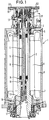
- the spindle unit 1 of a universal machine tool shown in FIG. 1 comprises a work spindle 2 designed as a hollow shaft, which is rotatably supported by means of a bearing arrangement 3, 4 in two end bearing caps 5, 6 of a spindle housing 7.
- the work spindle 2 is driven by a drive motor 8, the rotor of which is arranged in the spindle housing 7 between the two bearing caps 5, 6 9 concentrically surrounds the work spindle 2 and is connected to it in a rotationally fixed manner.
- the spindle unit 1 contains a clamping unit 11 with an actuating mechanism 12.
- the clamping unit 11 comprises a hollow clamping bush 13 which is fastened to the front end of a clamping rod 16 which is provided with a through hole 14 and is preloaded via a plate pack 15.
- At the front end of the clamping bush 13 laterally pivotable grippers 17 are arranged, which are pressed in the clamping position by a projection 18 on the inner wall of the work spindle 2 for engagement in a corresponding groove of a tool or a tool holder.
- the plate spring assembly 15 is supported on the one hand on a ring shoulder 19 in the work spindle 2 and on the other hand on a collar 20 at the rear area of the tension rod 16.
- the actuating device 12 is designed as a hydraulic cylinder / piston unit which is accommodated in a housing part 21 mounted on the rear bearing cover 6.
- the rearwardly open end of the housing part 21 is closed by a closure cover 22, which has a connecting flange 23 resting on the rear end face of the housing part 21 and a cylindrical inner part 24 projecting into the housing part 21.
- the outer surface of the cylindrical inner part 24 delimits, with the inner wall of the housing part 21, an annular space 25 in which an annular cylindrical piston 26 is arranged to be axially displaceable.
- the piston 26 has a front area 27 facing the work spindle 2 with a smaller outside diameter and a rear area 28 with a larger outside diameter.
- An annular End face 29 at the transition between the areas serves as a piston surface for pressurizing the piston 26 in the retracting direction.
- a fluid channel 30 leading to the annular end face 29 is provided in the housing part 21.
- the rear end surface 31 of the area 28 forms the piston surface for pressurizing the piston in the extension direction.
- a fluid channel 32 arranged in the connecting flange 23 leads to the end face 31.
- the inner wall of the housing part 21 is stepped via an annular shoulder 33, against which the annular end face 29 comes to rest in the fully extended position of the piston 26.
- Sealing elements 34 for sealing the piston 26 with respect to the housing part 21 and the cylindrical inner part 24 are arranged in the rear region 28 of the piston 26.
- a seal 35 arranged in the housing part 21 bears on the outside against the front region 27 of the piston 26.
- the piston 26 presses on an axially displaceable pressure ring 36, to which cylinder pins 37 acting on the tension rod 16 are fastened.
- the cylindrical pins 37 are screwed into corresponding threaded bores in the pressure ring 36 via rear threaded pins 38 and rest with their front end faces 39 on a rear annular collar 40 of the tension rod 15.
- the cylindrical pins 37 are inserted into bores 41 of an intermediate bush 42, which is screwed into the rear end of the work spindle 2.
- the pressure ring 36 with its inner bore 44 is axially displaceably guided on a rear cylinder shoulder 43 of the intermediate bush 42 and axially secured by a spring ring 45 arranged at the end of the cylinder shoulder 43.
- the intermediate bush 42 has a stepped through hole 46, in the front area with the larger inner diameter, a cylindrical end projection 47 of the tension rod 16 is guided in a sealing and axially displaceable manner.
- a hollow connecting piece 48 of a rotating union 49 is pressed in in a pressure-tight manner.
- the rotating union 49 is used to transfer a pressurized coolant from a stationary supply line 50 into the clamping unit 11 rotating during machining with the work spindle 2, via which the coolant reaches a coolant channel running through the tool.
- the supply line 50 for the coolant is also arranged in the connecting flange 23 and leads to an inlet of the rotating union 49.
- the rotating union 49 has a mating ring 51 which is fixed to the rear end face of the connecting piece 48 and which bears against a sliding ring 52 on the front end face of a disk-shaped enlarged part 53 of an axially movable sleeve 54.
- the counter ring 51 and the slide ring 52 are preferably made of ceramic.
- the sleeve 54 is guided with its rear cylindrical part 55 axially displaceably in a corresponding bore of a receiving bushing 56 and sealed by a sealing ring 57.
- the disc-shaped part 53 of the sleeve 54 is received in an enlarged section 58 and is acted upon by a spring 59 in the direction of the separation of the slide ring and the counter ring.
- Centering pins 60 are fixed in the receiving bushing 56 for centering and securing the sleeve 54, on which the disk-shaped part 53 is slidably guided via corresponding bores 61.
- the receptacle 56 is mounted on screws 62 in a corresponding recess 63 sealed by a sealing ring 64 on the inside of the closure cover 22.
- a locking ring 65 with a seal 66 is arranged on the end face of the sealing cover 22 facing the working spindle 2.
- the coolant is introduced into the spindle head 1 via the feed line 50 and arrives at the input of the rotary feedthrough 49.
- the coolant pressure acts on the rear end face 67 of the sleeve 54 and thus presses the slide ring 52 on the front end of the sleeve 54 against the counter ring 51.
- a tight connection is achieved between the non-rotating sleeve 54 and the connecting piece 48 of the rotating union 49 rotating with the work spindle 2 during processing.
- the cooling lubricant Via the hollow connecting piece 48 and the through hole within the intermediate bush 42, the cooling lubricant reaches the hollow clamping rod 16 and from there via the clamping bush 13 to the tool.
- an external toothing 68 is provided, into which a rotary encoder engages to detect the working spindle position.
- a limit switch 69 facing the outer surface of the pressure ring 36 for detecting the position of the tool clamp.
- the piston 26 is pressurized with a pressure fluid via the fluid channel 32, wherein it is moved from the clamping position shown in the right half of FIG. 2 to the release position shown in the left half of the figure.
- the piston 26 pushes the tension rod 16 forward over the pressure ring 36 and the cylindrical pins 37, i.e. 2 downwards, with the disk spring assembly 15 being compressed.
- the clamping bush 13 is also moved downward, the grippers 17 reaching an enlarged area. There they are spread outwards via springs and release the tool.
- the fluid channel 30 is pressurized, the piston 26 moving from the release position into the clamping position and the clamping rod 16 with the clamping bush 13 being drawn into the working spindle 2 under the action of the plate spring assembly 15.
- the grippers 17 are also pressed inwards and engage in the annular groove on a tool inserted into the work spindle 2.
- the piston 26 retracts so far that its front end face is spaced from the pressure ring 36 in the clamping position. This prevents the pressure ring rotating during machining with the work spindle 2 from rubbing against the piston 26 and causing wear and tear.
Abstract
Die Erfindung betrifft eine Spindeleinheit für Werkzeugmaschinen, mit einer in einem Gehäuse (7) drehbar gelagerten und durch einen Motor (8) antreibbaren Arbeitsspindel (2) zur Aufnahme eines Werkzeugs, einer Spanneinheit (11) mit Betätigungseinrichtung sowie einer inneren Kühlmittelzufuhr (14, 19) zum Werkzeug. Eine kurze und kompakte Spindeleinheit wird erfindungsgemäß dadurch geschaffen, daß die innere Kühlmittelzufuhr (14, 49) in die Spanneinheit (11) integriert ist und eine innerhalb der Betätigungseinrichtung (12) angeordnete Drehdurchführung (49) zur Überleitung des Kühlmittels von einer stationären Zufuhrleitung (50) in die Spanneinheit (11) aufweist. <IMAGE>The invention relates to a spindle unit for machine tools, with a work spindle (2) rotatably mounted in a housing (7) and drivable by a motor (8) for receiving a tool, a clamping unit (11) with an actuating device and an internal coolant supply (14, 19 ) to the tool. According to the invention, a short and compact spindle unit is created in that the internal coolant supply (14, 49) is integrated in the clamping unit (11) and a rotary feedthrough (49) arranged within the actuating device (12) for transferring the coolant from a stationary supply line (50 ) in the clamping unit (11). <IMAGE>
Description
Die Erfindung betrifft eine Spindeleinheit für Werkzeugmaschinen, mit einer in einem Gehäuse drehbar gelagerten und durch einen Motor antreibbaren Arbeitsspindel zur Aufnahme eines Werkzeugs, einer Spanneinheit mit Betätigungseinrichtung sowie einer inneren Kühlmittelzufuhr zum Werkzeug.The invention relates to a spindle unit for machine tools, with a work spindle rotatably mounted in a housing and drivable by a motor for receiving a tool, a clamping unit with an actuating device and an internal coolant supply to the tool.
Bei herkömmlichen Spindeleinheiten mit innerer Kühlmittelzufuhr sind die Bauelemente zur Einspeisung des Kühlmittels von stationären Rohrleitungen in die bei der Bearbeitung rotierenden Teile der Spanneinheit als separate Einheit im Anschluß an die Betätigungseinrichtung angeordnet. Dadurch erreicht die gesamte Spindeleinheit eine beträchtliche Baulänge, was insbesondere bei verschwenkbaren Spindeleinheiten zu Einschränkungen im Arbeitsraum der Werkzeugmaschine führt.In conventional spindle units with internal coolant supply, the components for feeding the coolant from stationary pipes into the rotating parts of the clamping unit during processing are arranged as a separate unit following the actuating device. Thereby the entire spindle unit reaches a considerable overall length, which leads to restrictions in the working space of the machine tool, in particular in the case of pivotable spindle units.
Aufgabe der Erfindung ist es, eine kurze und kompakte Spindeleinheit mit innerer Kühlmittelzufuhr zu schaffen.The object of the invention is to provide a short and compact spindle unit with an internal coolant supply.
Diese Aufgabe wird erfindungsgemäß dadurch gelöst, daß die innere Kühlmittelzufuhr in die Spanneinheit integriert ist und eine in der Betätigungseinrichtung angeordnete Drehdurchführung aufweist.This object is achieved in that the internal coolant supply is integrated in the clamping unit and has a rotating union arranged in the actuating device.
Durch die Integration der Kühlmittelzufuhr innerhalb der Spanneinheit ergibt sich eine äußerst kompakte Baueinheit aus Betätigungsmechanismus und Drehdurchführung, so daß die Baulänge der Spindeleinheit nicht vergrößert wird. Daher ist eine derartige Spindeleinheit insbesondere auch für den Einsatz als Schwenkspindel geeignet, da der für die Verschwenkung erforderliche Platzbedarf im Arbeitsraum der Werkzeugmaschine in der Regel beschränkt ist.The integration of the coolant supply within the clamping unit results in an extremely compact structural unit consisting of the actuating mechanism and the rotating union, so that the overall length of the spindle unit is not increased. Such a spindle unit is therefore also particularly suitable for use as a pivot spindle, since the space required for pivoting in the working space of the machine tool is generally limited.
Eine zweckmäßige Ausgestaltung der Erfindung zeichnet sich dadurch aus, daß der Betätigungsmechanismus als Zylinder/Kolben-Einheit mit einem ringzylindrischen Kolben ausgebildet ist, der in einem Ringraum zwischen einem Gehäuseteil und einem zylindrischen Innenteil angeordnet ist. In das zylindrische Innenteil ist die Drehdurchführung vom ringzylindrischen Kolben konzentrisch umgeben eingebaut. Dadurch sind sowohl der Betätigungsmechanismus als auch die Drehdurchführung auf besonders platzsparende Weise angeordnet.An advantageous embodiment of the invention is characterized in that the actuating mechanism is designed as a cylinder / piston unit with an annular cylindrical piston which is arranged in an annular space between a housing part and a cylindrical inner part. In the cylindrical inner part, the rotating union is built in concentrically surrounded by the ring-cylindrical piston. As a result, both the actuating mechanism and the rotating union are arranged in a particularly space-saving manner.
Zur abgedichteten Überleitung der Kühlflüssigkeit von der stationären Zufuhrleitung in die bei der Bearbeitung rotierenden Teile der Spanneinheit weist die Drehdurchführung zweckmäßigerweise einen mit den rotierenden Teilen verbundenen Anschlußstutzen und eine durch den Kühlmitteldruck dichtend an den Anschlußstutzen angepresste Hülse auf, die in die Zufuhrleitung mündet. An den aneinandergrenzenden Stirnflächen der Hülse und des Anschlußstutzens sind zweckmäßigerweise ein Gleit- bzw. Gegenring aus verschleißfestem Material angeordnet.For the sealed transfer of the coolant from the stationary supply line into the rotating parts of the clamping unit during processing, the rotating union expediently has a connecting piece connected to the rotating parts and a sleeve which is pressed against the connecting piece by the coolant pressure and which opens into the supply line. A sliding or mating ring made of wear-resistant material is expediently arranged on the adjoining end faces of the sleeve and the connecting piece.
Auf die zur Zufuhrleitung gewandte hintere Stirnfläche der Hülse wirkt der Kühlmitteldruck bei der Bearbeitung mit innerer Kühlmittelzufuhr ein und drückt die Hülse gegen das Anschlußstück. Dadurch wird eine vorteilhafte Dichtverbindung zwischen der Hülse und dem Anschlußstutzen erreicht. Bei einer Bearbeitung ohne Kühlmittel wirkt kein Druck auf die hintere Stirnfläche der Hülse, so daß diese bei einer zweckmäßigen Ausführung durch eine Feder vom Anschlußstutzen weggedrückt wird, wenn kein Kühlmitteldruck auf die Hülse einwirkt. Dies führt dazu, daß die an den aneinandergrenzenden Stirnflächen von Anschlußstutzen und Hülse angeordneten Dichtringe nur dann aufeinandergleiten, wenn eine innere Kühlmittelzufuhr benötigt und daher eine dichtende Verbindung erforderlich ist. Dadurch kann ein zu starker Verschleiß zwischen den beiden Ringen vermieden werden.The coolant pressure during processing with internal coolant supply acts on the rear end face of the sleeve facing the supply line and presses the sleeve against the connecting piece. This provides an advantageous sealing connection between the sleeve and the connection piece. When machining without coolant, no pressure acts on the rear end face of the sleeve, so that, in an expedient embodiment, this is pressed away from the connecting piece by a spring when no coolant pressure acts on the sleeve. This leads to the fact that the sealing rings arranged on the adjoining end faces of the connecting piece and sleeve only slide onto one another when an internal coolant supply is required and therefore a sealing connection is required. This prevents excessive wear between the two rings.
Die Kraftübertragung von dem Kolben auf die Spannstange der Spanneinheit erfolgt in vorteilhafter Weise über einen axial verschiebbaren Druckring, an dem auf die Spanneinheit wirkende Zylinderstifte befestigt sind. Die Zylinderstifte sind in den entsprechenden Bohrungen einer in das hintere Ende der Arbeitsspindel eingeschraubten Zwischenbuchse geführt.The power transmission from the piston to the tensioning rod of the tensioning unit takes place in an advantageous manner via an axially displaceable pressure ring to which cylinder pins acting on the tensioning unit are fastened. The cylinder pins are one in the corresponding holes in the rear Screwed in intermediate bushing at the end of the work spindle.
Eine besonders kompakte Bauweise der Spindeleinheit wird dadurch erreicht, daß diese als Motorspindel ausgebildet ist. Dabei wird die Spindel konzentrisch vom Motor umgeben, dessen Rotor drehfest mit der Arbeitsspindel verbunden ist.A particularly compact design of the spindle unit is achieved in that it is designed as a motor spindle. The spindle is concentrically surrounded by the motor, the rotor of which is connected to the work spindle so that it cannot rotate.
Weitere Besonderheiten und Vorzüge der Erfindung ergeben sich aus der folgenden Beschreibung eines bevorzugten Ausführungsbeispiels anhand der Zeichnung. Es zeigen:
- Fig. 1
- einen Längsschnitt durch eine Spindeleinheit gemäß der Erfindung und
- Fig. 2
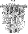
- eine vergrößerte Schnittdarstellung des Betätigungsmechanismus für die Spanneinheit mit integrierter Kühlmittelzufuhr.
- Fig. 1
- a longitudinal section through a spindle unit according to the invention and
- Fig. 2
- an enlarged sectional view of the actuating mechanism for the clamping unit with integrated coolant supply.
In beiden Figuren ist die in der Spindeleinheit integrierte Spanneinheit jeweils in der linken Bildhälfte in der Lösestellung und in der rechten Bildhälfte in der Spannstellung dargestellt.In both figures, the clamping unit integrated in the spindle unit is shown in the left position in the release position and in the right position in the clamping position.
Die in Fig. 1 dargestellte Spindeleinheit 1 einer Universal-Werkzeugmaschine umfaßt eine als Hohlwelle ausgebildete Arbeitsspindel 2, die über eine Lageranordnung 3, 4 in zwei stirnseitigen Lagerdeckeln 5, 6 eines Spindelgehäuses 7 drehbar gelagert ist. Der Antrieb der Arbeitsspindel 2 erfolgt durch einen im Spindelgehäuse 7 zwischen den beiden Lagerdeckeln 5, 6 angeordneten Antriebsmotor 8, dessen Rotor 9 die Arbeitsspindel 2 konzentrisch umgibt und mit dieser drehfest verbunden ist.The spindle unit 1 of a universal machine tool shown in FIG. 1 comprises a
Die Spindeleinheit 1 enthält eine Spanneinheit 11 mit einem Betätigungsmechanismus 12. Die Spanneinheit 11 umfaßt eine hohle Spannbuchse 13, die am vorderen Ende einer mit einer Durchgangsbohrung 14 versehenen und über ein Tellerpaket 15 vorgespannten Spannstange 16 befestigt ist. An dem vorderen Ende der Spannbuchse 13 sind seitlich verschwenkbare Greifer 17 angeordnet, die in der Spannstellung durch einen Vorsprung 18 an der Innenwandung der Arbeitsspindel 2 zum Eingriff in eine entsprechende Nut eines Werkzeugs bzw. einer Werkzeugaufnahme nach innen gedrückt sind. Das Tellerfederpaket 15 ist einerseits auf einem Ringabsatz 19 in der Arbeitsspindel 2 und andererseits auf einem Bund 20 am hinteren Bereich der Spannstange 16 abgestützt.The spindle unit 1 contains a
Wie insbesondere aus Fig. 2 hervorgeht, ist die Betätigungseinrichtung 12 als hydraulische Zylinder/Kolben-Einheit ausgebildet, die in einem am hinteren Lagerdeckel 6 montierten Gehäuseteil 21 untergebracht ist. Das nach hinten offene Ende des Gehäuseteils 21 ist durch einen Verschlußdeckel 22 geschlossen, der einen an der hinteren Stirnfläche des Gehäuseteils 21 anliegenden Anschlußflansch 23 und einen in das Gehäuseteil 21 ragenden zylindrischen Innenteil 24 aufweist. Die Mantelfläche des zylindrischen Innenteils 24 begrenzt mit der Innenwand des Gehäuseteils 21 einen Ringraum 25, in dem ein ringzylindrischer Kolben 26 axial verschiebbar angeordnet ist. Der Kolben 26 weist einen zur Arbeitsspindel 2 gewandten vorderen Bereich 27 mit geringerem Außendurchmesser und einen hinteren Bereich 28 mit größerem Außendurchmesser auf. Eine ringförmige Stirnfläche 29 am Übergang zwischen den Bereichen dient als Kolbenfläche zur Druckbeaufschlagung des Kolbens 26 in Einfahrrichtung. In dem Gehäuseteil 21 ist ein zu der ringförmigen Stirnfläche 29 führender Fluidkanal 30 vorgesehen. Die hintere Endfläche 31 des Bereichs 28 bildet die Kolbenfläche zur Druckbeaufschlagung des Kolbens in Ausfahrrichtung. Zu der Endfläche 31 führt ein in den Anschlußflansch 23 angeordneter Fluidkanal 32. Die Innenwand des Gehäuseteils 21 ist über einen Ringabsatz 33 abgestuft, an dem die ringförmige Stirnfläche 29 in der vollständig ausgefahrenen Stellung des Kolbens 26 zur Anlage gelangt. In dem hinteren Bereich 28 des Kolbens 26 sind Dichtelemente 34 zur Abdichtung des Kolbens 26 gegenüber dem Gehäuseteil 21 und dem zylindrischen Innenteil 24 angeordnet. Eine im Gehäuseteil 21 angeordnete Dichtung 35 liegt an der Außenseite am vorderen Bereich 27 des Kolbens 26 an.As can be seen in particular from FIG. 2, the actuating
Der Kolben 26 drückt beim Ausfahren auf einen axial verschiebbaren Druckring 36, an dem auf die Spannstange 16 wirkende Zylinderstifte 37 befestigt sind. Die Zylinderstifte 37 sind über rückseitige Gewindezapfen 38 in entsprechende Gewindebohrungen im Druckring 36 eingeschraubt und liegen mit ihren vorderen Stirnflächen 39 an einem hinteren Ringbund 40 der Spannstange 15 an. An ihrem Außenumfang sind die Zylinderstifte 37 in Bohrungen 41 einer Zwischenbuchse 42 eingeführt, die in das hintere Ende der Arbeitsspindel 2 eingeschraubt ist. Auf einem hinteren Zylinderabsatz 43 der Zwischenbuchse 42 ist der Druckring 36 mit seiner Innenbohrung 44 axial verschiebbar geführt und durch einen am Ende des Zylinderabsatzes 43 angeordneten Federring 45 axial gesichert. Die Zwischenbuchse 42 hat eine abgesetzte Durchgangsbohrung 46, in deren vorderem Bereich mit dem größeren Innendurchmesser ein zylindrischer Endansatz 47 der Spannstange 16 dichtend und axial verschiebbar geführt ist. In den hinteren Bereich der Durchgangsbohrung 46 mit dem geringeren Innendurchmesser ist ein hohler Anschlußstutzen 48 einer Drehdurchführung 49 druckdicht eingepreßt.When extended, the
Die Drehdurchführung 49 dient zur Überleitung eines unter Druck stehenden Kühlmittels von einer stationären Zufuhrleitung 50 in die bei der Bearbeitung mit der Arbeitsspindel 2 rotierende Spanneinheit 11, über die das Kühlmittel zu einem durch das Werkzeug verlaufenden Kühlmittelkanal gelangt. Die Zufuhrleitung 50 für das Kühlmittel ist ebenfalls in dem Anschlußflansch 23 angeordnet und führt zu einem Einlaß der Drehdurchführung 49.The rotating
Für die abgedichtete Einspeisung des Kühlmittels weist die Drehdurchführung 49 einen an der hinteren Stirnfläche des Anschlußstutzens 48 fixierten Gegenring 51 auf, der an einem Gleitring 52 an der vorderen Stirnfläche eines scheibenförmig erweiterten Teils 53 einer axial beweglichen Hülse 54 anliegt. Der Gegenring 51 und der Gleitring 52 bestehen vorzugsweise aus Keramik. Die Hülse 54 ist mit ihrem hinteren zylindrischen Teil 55 in einer entsprechenden Bohrung einer Aufnahmebuchse 56 axial verschiebbar geführt und über einen Dichtungsring 57 abgedichtet. Der scheibenförmig erweiterte Teil 53 der Hülse 54 ist in einem vergrößerten Abschnitt 58 aufgenommen und wird durch eine Feder 59 in Richtung der Trennung von Gleit- und Gegenring beaufschlagt. Zur Zentrierung und Verdrehsicherung der Hülse 54 sind in der Aufnahmebuchse 56 Zentrierstifte 60 fixiert, auf denen der scheibenförmig erweiterte Teil 53 über entsprechende Bohrungen 61 verschiebbar geführt ist.For the sealed supply of the coolant, the rotating
Die Aufnahmebuchse 56 ist über Schrauben 62 in einer entsprechenden Ausnehmung 63 durch einen Dichtring 64 abgedichtet an der Innenseite des Verschlußdeckels 22 montiert. An der zur Arbeitsspindel 2 gerichteten Stirnseite des Verschlußdeckels 22 ist ein Verschlußring 65 mit einer Dichtung 66 angeordnet.The
Über die Zufuhrleitung 50 wird das Kühlmittel in den Spindelkopf 1 eingeleitet und gelangt zu dem Eingang der Drehdurchführung 49. Der Kühlmitteldruck wirkt auf die hintere Stirnfläche 67 der Hülse 54 und drückt somit den Gleitring 52 am vorderen Ende der Hülse 54 an den Gegenring 51 an. Dadurch wird eine dichte Verbindung zwischen der verdrehgesicherten Hülse 54 und dem mit der Arbeitsspindel 2 bei der Bearbeitung rotierenden Anschlußstutzen 48 der Drehdurchführung 49 erreicht. Über den hohlen Anschlußstutzen 48 und die Durchgangsbohrung innerhalb der Zwischenbuchse 42 gelangt das Kühlschmiermittel in die hohle Spannstange 16 und von dort über die Spannbuchse 13 zum Werkzeug. Wenn kein Kühlmittel zugeführt wird, wirkt kein Kühlmitteldruck auf die hintere Stirnfläche 67 der Hülse 54, so daß diese durch die Feder 59 vom Anschlußstutzen 48 wegbewegt wird, wobei der Gleitring 52 vom Gegenring 51 wegbewegt wird. Dadurch wird erreicht, daß der Gleit- und Gegenring nur dann aneinanderreiben, wenn eine innere Kühlmittelzufuhr benötigt und daher einer dichtende Verbindung erforderlich ist. Damit kann der Verschleiß von Gleit- und Gegenring minimiert werden.The coolant is introduced into the spindle head 1 via the
An dem Außenumfang der Zwischenbuchse 42 ist eine Außenverzahnung 68 vorgesehen, in die ein Drehgeber zur Erfassung der Arbeitsspindelposition eingreift. An der Außenseite des Gehäuseteils 21 ist ferner ein der Mantelfläche des Druckrings 36 zugewandter Endschalter 69 zur Erfassung der Position des Werkzeugspanners angeordnet.On the outer circumference of the intermediate bush 42, an
Zum Lösen des Werkzeugs wird der Kolben 26 über den Fluidkanal 32 mit einem Druckfluid beaufschlagt, wobei er aus der in Fig. 2 in der rechten Bildhälfte dargestellten Spannstellung in die in der linken Bildhälfte dargestellte Lösestellung bewegt wird. Der Kolben 26 schiebt die Spannstange 16 über den Druckring 36 und die Zylinderstifte 37 nach vorne, d.h. in Fig. 2 nach unten, wobei das Tellerfederpaket 15 zusammengedrückt wird. Dadurch wird auch die Spannbuchse 13 nach unten bewegt, wobei die Greifer 17 in einen erweiterten Bereich gelangen. Dort werden sie über Federn nach außen gespreizt und geben das Werkzeug frei.To release the tool, the
Zum Spannen des Werkzeugs wird der Fluidkanal 30 mit Druck beaufschlagt, wobei der Kolben 26 aus der Lösestellung in die Spannstellung bewegt und die Spannstange 16 mit der Spannbuchse 13 unter der Wirkung des Tellerfederpakets 15 in die Arbeitsspindel 2 eingezogen wird. Dabei werden auch die Greifer 17 nach innen gedrückt und greifen in die Ringnut an einem in die Arbeitsspindel 2 eingesetzten Werkzeug ein. Der Kolben 26 fährt soweit ein, daß seine vordere Stirnfläche in der Spannstellung von dem Druckring 36 beabstandet ist. Dadurch wird vermieden, daß der bei der Bearbeitung mit der Arbeitsspindel 2 rotierende Druckring an dem Kolben 26 reibt und Verschleißerscheinungen hervorruft.To clamp the tool, the
Claims (11)
die innere Kühlmittelzufuhr (14, 49) in die Spanneinheit (11) integriert ist und eine innerhalb der Betätigungseinrichtung (12) angeordnete Drehdurchführung (49) zur Überleitung des Kühlmittels von einer stationären Zufuhrleitung (50) in die Spanneinheit (11) aufweist.Spindle unit for machine tools, with
the internal coolant supply (14, 49) is integrated in the clamping unit (11) and has a rotary feedthrough (49) arranged within the actuating device (12) for transferring the coolant from a stationary supply line (50) into the clamping unit (11).
Applications Claiming Priority (2)
| Application Number | Priority Date | Filing Date | Title |
|---|---|---|---|
| DE29520427U DE29520427U1 (en) | 1995-12-22 | 1995-12-22 | Spindle unit for machine tools |
| DE29520427U | 1995-12-22 |
Publications (3)
| Publication Number | Publication Date |
|---|---|
| EP0780192A1 true EP0780192A1 (en) | 1997-06-25 |
| EP0780192B1 EP0780192B1 (en) | 2000-02-16 |
| EP0780192B2 EP0780192B2 (en) | 2003-01-29 |
Family
ID=8017135
Family Applications (1)
| Application Number | Title | Priority Date | Filing Date |
|---|---|---|---|
| EP96118896A Expired - Lifetime EP0780192B2 (en) | 1995-12-22 | 1996-11-25 | Spindle unit for machine-tools |
Country Status (5)
| Country | Link |
|---|---|
| US (1) | US5782586A (en) |
| EP (1) | EP0780192B2 (en) |
| JP (1) | JP3764229B2 (en) |
| DE (1) | DE29520427U1 (en) |
| ES (1) | ES2144689T5 (en) |
Cited By (6)
| Publication number | Priority date | Publication date | Assignee | Title |
|---|---|---|---|---|
| DE10047851A1 (en) * | 2000-09-27 | 2002-05-02 | Bielomatik Leuze & Co | Fluid input for spindle head has inner piston track made in one with support surface |
| EP1787744A1 (en) * | 2005-11-17 | 2007-05-23 | DECKEL MAHO Pfronten GmbH | Motor spindle |
| ITMI20131315A1 (en) * | 2013-08-02 | 2015-02-03 | Antonio Ferraro | LOCKING DEVICE FOR TOOLS |
| DE102017008654A1 (en) | 2017-09-14 | 2019-03-14 | Franz Kessler Gmbh | Motor spindle for a machine tool with integrated cooling and rotary feedthrough module |
| CN110091251A (en) * | 2018-12-04 | 2019-08-06 | 杭州众硅电子科技有限公司 | A kind of integrated form polishing wafer main shaft |
| DE102018112169A1 (en) * | 2018-05-22 | 2019-11-28 | Berg & Co. Gmbh | Spindle unit for machine tools |
Families Citing this family (22)
| Publication number | Priority date | Publication date | Assignee | Title |
|---|---|---|---|---|
| US5769579A (en) * | 1996-04-26 | 1998-06-23 | Thermwood Corporation | Toolhead assembly for machine tools and method of making same |
| DE29812170U1 (en) † | 1998-07-07 | 1998-09-10 | Jaeger Alfred | Interchangeable motor spindle for a machine tool |
| SE519206C2 (en) * | 1999-03-23 | 2003-01-28 | Lind Finance & Dev Ab | Device at tool spindle provided with a rotor, the device comprising means for cooling the rotor |
| US6533509B1 (en) * | 2001-09-17 | 2003-03-18 | Gregory S. Antoun | Tool holder unclamp mechanism for a milling machine |
| US7677847B2 (en) * | 2002-03-26 | 2010-03-16 | Siemens Aktiengesellschaft | Sealing assembly for a spindle |
| DE10242449B4 (en) * | 2002-09-11 | 2006-01-19 | Zimmer GmbH, Technische Werkstätten | Machine tool spindle with mechanical seal |
| DE10257336A1 (en) * | 2002-12-06 | 2004-06-17 | Röhm Gmbh | solvent awareness |
| JP4730939B2 (en) * | 2004-03-31 | 2011-07-20 | コマツNtc株式会社 | Spindle device |
| US6951256B1 (en) * | 2004-04-24 | 2005-10-04 | Ru Song Xiao | Machine tool having coaxial driving device |
| DE102005022713A1 (en) * | 2005-05-18 | 2006-11-23 | Zf Friedrichshafen Ag | Machine tool transmission, in particular spindle gear |
| US7972096B2 (en) * | 2005-05-26 | 2011-07-05 | Makino Milling Machine Co., Ltd. | Spindle device of machine tool |
| FR2935915B1 (en) * | 2008-09-18 | 2010-10-08 | Cooper Power Tools Sas | MACHINING MACHINE AND ASSOCIATED MACHINING METHOD |
| DE102009044105A1 (en) * | 2009-09-25 | 2011-03-31 | Röhm Gmbh | Clamping device with stationary release unit |
| DE102010002019A1 (en) * | 2010-02-17 | 2011-08-18 | MAG IAS GmbH, 73033 | Machine tool and method for machining a workpiece |
| DE102010039096B4 (en) | 2010-08-09 | 2014-05-15 | Mag Ias Gmbh | Tool spindle-tool combination for a machine tool |
| CH705129B1 (en) * | 2011-06-17 | 2015-06-30 | Mario Baldaccini Meccanica Di Prec E | Device and process for the electro-spindle in the tool change with the said device. |
| US8956093B1 (en) * | 2011-11-11 | 2015-02-17 | Mag Ias, Llc | Seal arrangement for a high speed spindle with through the spindle cooling |
| CN102950297A (en) * | 2012-12-06 | 2013-03-06 | 无锡博华机电有限公司 | Cooling and circulating passage of electric main shaft |
| DE102015114727A1 (en) * | 2015-09-03 | 2017-03-09 | Alfing Kessler Sondermaschinen Gmbh | Machine tool with a finishing spindle |
| DE102016114036A1 (en) * | 2016-07-29 | 2018-02-01 | Ott-Jakob Spanntechnik Gmbh | Work spindle cooling device and machine tool processing unit with such a work spindle cooling device |
| CN107617974B (en) * | 2017-09-26 | 2023-12-08 | 深圳市富信泰科技有限公司 | Polisher |
| JP7016787B2 (en) * | 2018-10-31 | 2022-02-07 | 日精ホンママシナリー株式会社 | Spindle for rotary tools |
Citations (4)
| Publication number | Priority date | Publication date | Assignee | Title |
|---|---|---|---|---|
| JPS6034244A (en) * | 1983-07-30 | 1985-02-21 | Okuma Mach Works Ltd | Air supply device |
| DE3706534C1 (en) * | 1987-02-28 | 1988-04-28 | Ott Gmbh A | Collet chuck for a chucking fixture insertable into a machine-tool spindle |
| US4957398A (en) * | 1987-04-30 | 1990-09-18 | Friedrich Deckel Aktiengesellschaft | Two-section tool spindle having a channel for carrying pressurized fluid |
| US5420388A (en) * | 1989-03-29 | 1995-05-30 | Charmilles Technologies | Tool-holder and rapid rotary spindle |
Family Cites Families (6)
| Publication number | Priority date | Publication date | Assignee | Title |
|---|---|---|---|---|
| DE3876622D1 (en) * | 1988-07-11 | 1993-01-21 | Blessing Wilhelm Fa | CHUCK QUICK-CHANGE DEVICE. |
| DE3838318A1 (en) * | 1988-11-11 | 1990-05-17 | Krupp Widia Gmbh | TOOLING SYSTEM |
| US4915553A (en) * | 1989-02-01 | 1990-04-10 | Tree Machine Tool, Co. | Tool retention and ejection mechanism |
| JPH0398716A (en) * | 1989-09-09 | 1991-04-24 | Brother Ind Ltd | Machine tool |
| US5096347A (en) * | 1990-04-20 | 1992-03-17 | Mori Seiko Co., Ltd. | Spring clamp with clamped condition holding device |
| JPH07109269B2 (en) † | 1990-09-04 | 1995-11-22 | 山田興産株式会社 | Rotary joint for drawbar |
-
1995
- 1995-12-22 DE DE29520427U patent/DE29520427U1/en not_active Expired - Lifetime
-
1996
- 1996-11-25 EP EP96118896A patent/EP0780192B2/en not_active Expired - Lifetime
- 1996-11-25 ES ES96118896T patent/ES2144689T5/en not_active Expired - Lifetime
- 1996-12-20 US US08/770,959 patent/US5782586A/en not_active Expired - Lifetime
- 1996-12-20 JP JP34178896A patent/JP3764229B2/en not_active Expired - Lifetime
Patent Citations (4)
| Publication number | Priority date | Publication date | Assignee | Title |
|---|---|---|---|---|
| JPS6034244A (en) * | 1983-07-30 | 1985-02-21 | Okuma Mach Works Ltd | Air supply device |
| DE3706534C1 (en) * | 1987-02-28 | 1988-04-28 | Ott Gmbh A | Collet chuck for a chucking fixture insertable into a machine-tool spindle |
| US4957398A (en) * | 1987-04-30 | 1990-09-18 | Friedrich Deckel Aktiengesellschaft | Two-section tool spindle having a channel for carrying pressurized fluid |
| US5420388A (en) * | 1989-03-29 | 1995-05-30 | Charmilles Technologies | Tool-holder and rapid rotary spindle |
Non-Patent Citations (1)
| Title |
|---|
| PATENT ABSTRACTS OF JAPAN vol. 9, no. 162 (M - 394) 6 July 1985 (1985-07-06) * |
Cited By (11)
| Publication number | Priority date | Publication date | Assignee | Title |
|---|---|---|---|---|
| DE10047851A1 (en) * | 2000-09-27 | 2002-05-02 | Bielomatik Leuze & Co | Fluid input for spindle head has inner piston track made in one with support surface |
| EP1787744A1 (en) * | 2005-11-17 | 2007-05-23 | DECKEL MAHO Pfronten GmbH | Motor spindle |
| US7326010B2 (en) | 2005-11-17 | 2008-02-05 | Deckel Maho Pfronten Gmbh | Motor spindle |
| ITMI20131315A1 (en) * | 2013-08-02 | 2015-02-03 | Antonio Ferraro | LOCKING DEVICE FOR TOOLS |
| EP2839910A2 (en) | 2013-08-02 | 2015-02-25 | Antonio Ferraro | Chuck locking device for spindles of machine tools |
| EP2839910A3 (en) * | 2013-08-02 | 2015-05-13 | Antonio Ferraro | Chuck locking device for spindles of machine tools |
| DE102017008654A1 (en) | 2017-09-14 | 2019-03-14 | Franz Kessler Gmbh | Motor spindle for a machine tool with integrated cooling and rotary feedthrough module |
| EP3456467A2 (en) | 2017-09-14 | 2019-03-20 | Franz Kessler GmbH | Motor spindle for a machine tool with integrated cooling and rotary transmission module |
| DE102018112169A1 (en) * | 2018-05-22 | 2019-11-28 | Berg & Co. Gmbh | Spindle unit for machine tools |
| DE102018112169B4 (en) | 2018-05-22 | 2020-01-23 | Berg & Co. Gmbh | Spindle unit for machine tools |
| CN110091251A (en) * | 2018-12-04 | 2019-08-06 | 杭州众硅电子科技有限公司 | A kind of integrated form polishing wafer main shaft |
Also Published As
| Publication number | Publication date |
|---|---|
| DE29520427U1 (en) | 1996-02-08 |
| ES2144689T3 (en) | 2000-06-16 |
| JPH09183039A (en) | 1997-07-15 |
| ES2144689T5 (en) | 2003-11-16 |
| US5782586A (en) | 1998-07-21 |
| EP0780192B1 (en) | 2000-02-16 |
| EP0780192B2 (en) | 2003-01-29 |
| JP3764229B2 (en) | 2006-04-05 |
Similar Documents
| Publication | Publication Date | Title |
|---|---|---|
| EP0780192B2 (en) | Spindle unit for machine-tools | |
| DE69002268T4 (en) | Cooling unit with fluid-operated seal. | |
| EP0498146A2 (en) | Swivelling lead-through for two different fluids | |
| DE4018543C1 (en) | ||
| EP1514047B1 (en) | Rotary feedthrough | |
| DE1925527C3 (en) | Pressure fluid operated chuck | |
| DE3114656C2 (en) | ||
| EP0509143B1 (en) | Tapping apparatus | |
| DE4335258A1 (en) | Pneumatic/mechanical clamping device for winding shafts, clamping heads and the like | |
| EP3275589B1 (en) | Working spindle cooling device and machine tool processing unit with a similar working spindle cooling device | |
| DE3512890C2 (en) | ||
| DE1552406A1 (en) | Machine tool | |
| EP0185170B1 (en) | Jaw chuck for turning-machines for machining workpieces under several axes | |
| DD204648A1 (en) | FLOW CONTROL DEVICE FOR GAS AND LIQUID MEDIA IN A TOOL MACHINE WORKING SPINDLE | |
| DE10319796A1 (en) | Hydraulic or pneumatic clamping fixture for tool/workpiece in machine tool e.g. lathe, has unrotatable radial and axial couplings for fluid supply and exhaust mounted respectively to fixture and spindle drive via counter pieces | |
| DE4402949C2 (en) | Machine tool with interchangeable machining heads | |
| DE2626692A1 (en) | CLAMPING DEVICE ON A MACHINE TOOL | |
| DE102019100072A1 (en) | Extractable clamping device and clamping unit with such a clamping device | |
| DE10043006C1 (en) | Actuating device for a tool or workpiece clamp in a machine tool spindle | |
| DE3615743A1 (en) | Collet vice for high gripping forces | |
| EP0528155A2 (en) | Chuck for machine tools | |
| DE102023110707B3 (en) | Clamping system for a mandrel | |
| DE2658929A1 (en) | Pressure medium-operated chuck - has working chamber containing axially movable piston with integral clamping sleeve | |
| DE3636421A1 (en) | Automatic quick-acting clamping attachment for tools in drilling and milling spindles | |
| EP0172571B1 (en) | Chuck |
Legal Events
| Date | Code | Title | Description |
|---|---|---|---|
| PUAI | Public reference made under article 153(3) epc to a published international application that has entered the european phase |
Free format text: ORIGINAL CODE: 0009012 |
|
| AK | Designated contracting states |
Kind code of ref document: A1 Designated state(s): CH DE ES FR GB IT LI |
|
| 17P | Request for examination filed |
Effective date: 19971215 |
|
| 17Q | First examination report despatched |
Effective date: 19980930 |
|
| GRAG | Despatch of communication of intention to grant |
Free format text: ORIGINAL CODE: EPIDOS AGRA |
|
| GRAG | Despatch of communication of intention to grant |
Free format text: ORIGINAL CODE: EPIDOS AGRA |
|
| GRAH | Despatch of communication of intention to grant a patent |
Free format text: ORIGINAL CODE: EPIDOS IGRA |
|
| GRAH | Despatch of communication of intention to grant a patent |
Free format text: ORIGINAL CODE: EPIDOS IGRA |
|
| GRAA | (expected) grant |
Free format text: ORIGINAL CODE: 0009210 |
|
| AK | Designated contracting states |
Kind code of ref document: B1 Designated state(s): CH DE ES FR GB IT LI |
|
| REG | Reference to a national code |
Ref country code: CH Ref legal event code: NV Representative=s name: MICHELI & CIE INGENIEURS-CONSEILS Ref country code: CH Ref legal event code: EP |
|
| GBT | Gb: translation of ep patent filed (gb section 77(6)(a)/1977) |
Effective date: 20000217 |
|
| ITF | It: translation for a ep patent filed |
Owner name: RACHELI & C. S.R.L. |
|
| ET | Fr: translation filed | ||
| REG | Reference to a national code |
Ref country code: ES Ref legal event code: FG2A Ref document number: 2144689 Country of ref document: ES Kind code of ref document: T3 |
|
| PLBQ | Unpublished change to opponent data |
Free format text: ORIGINAL CODE: EPIDOS OPPO |
|
| PLBI | Opposition filed |
Free format text: ORIGINAL CODE: 0009260 |
|
| 26 | Opposition filed |
Opponent name: HUELLER HILLE GMBH Effective date: 20000830 |
|
| PLBF | Reply of patent proprietor to notice(s) of opposition |
Free format text: ORIGINAL CODE: EPIDOS OBSO |
|
| PLBF | Reply of patent proprietor to notice(s) of opposition |
Free format text: ORIGINAL CODE: EPIDOS OBSO |
|
| REG | Reference to a national code |
Ref country code: GB Ref legal event code: IF02 |
|
| PLAW | Interlocutory decision in opposition |
Free format text: ORIGINAL CODE: EPIDOS IDOP |
|
| PLAW | Interlocutory decision in opposition |
Free format text: ORIGINAL CODE: EPIDOS IDOP |
|
| PUAH | Patent maintained in amended form |
Free format text: ORIGINAL CODE: 0009272 |
|
| STAA | Information on the status of an ep patent application or granted ep patent |
Free format text: STATUS: PATENT MAINTAINED AS AMENDED |
|
| 27A | Patent maintained in amended form |
Effective date: 20030129 |
|
| AK | Designated contracting states |
Designated state(s): CH DE ES FR GB IT LI |
|
| REG | Reference to a national code |
Ref country code: CH Ref legal event code: AEN Free format text: AUFRECHTERHALTUNG DES PATENTES IN GEAENDERTER FORM |
|
| GBTA | Gb: translation of amended ep patent filed (gb section 77(6)(b)/1977) | ||
| ET3 | Fr: translation filed ** decision concerning opposition | ||
| REG | Reference to a national code |
Ref country code: ES Ref legal event code: DC2A Date of ref document: 20030425 Kind code of ref document: T5 |
|
| REG | Reference to a national code |
Ref country code: FR Ref legal event code: PLFP Year of fee payment: 20 |
|
| PGFP | Annual fee paid to national office [announced via postgrant information from national office to epo] |
Ref country code: IT Payment date: 20151124 Year of fee payment: 20 Ref country code: CH Payment date: 20151125 Year of fee payment: 20 Ref country code: DE Payment date: 20151130 Year of fee payment: 20 Ref country code: GB Payment date: 20151130 Year of fee payment: 20 |
|
| PGFP | Annual fee paid to national office [announced via postgrant information from national office to epo] |
Ref country code: FR Payment date: 20151130 Year of fee payment: 20 Ref country code: ES Payment date: 20151221 Year of fee payment: 20 |
|
| REG | Reference to a national code |
Ref country code: DE Ref legal event code: R071 Ref document number: 59604458 Country of ref document: DE |
|
| REG | Reference to a national code |
Ref country code: CH Ref legal event code: PL |
|
| REG | Reference to a national code |
Ref country code: GB Ref legal event code: PE20 Expiry date: 20161124 |
|
| PG25 | Lapsed in a contracting state [announced via postgrant information from national office to epo] |
Ref country code: GB Free format text: LAPSE BECAUSE OF EXPIRATION OF PROTECTION Effective date: 20161124 |
|
| REG | Reference to a national code |
Ref country code: ES Ref legal event code: FD2A Effective date: 20170303 |
|
| PG25 | Lapsed in a contracting state [announced via postgrant information from national office to epo] |
Ref country code: ES Free format text: LAPSE BECAUSE OF EXPIRATION OF PROTECTION Effective date: 20161126 |