EP0779522B1 - Prozess zur Herstellung eines Bragg-Gitters in einem optischen Wellenleiter aus PZG-Fluoridglas sowie dadurch hergestelltes Bragg-Gitter - Google Patents
Prozess zur Herstellung eines Bragg-Gitters in einem optischen Wellenleiter aus PZG-Fluoridglas sowie dadurch hergestelltes Bragg-Gitter Download PDFInfo
- Publication number
- EP0779522B1 EP0779522B1 EP96402662A EP96402662A EP0779522B1 EP 0779522 B1 EP0779522 B1 EP 0779522B1 EP 96402662 A EP96402662 A EP 96402662A EP 96402662 A EP96402662 A EP 96402662A EP 0779522 B1 EP0779522 B1 EP 0779522B1
- Authority
- EP
- European Patent Office
- Prior art keywords
- fluoride glass
- waveguide
- photorefractive
- doped
- gratings
- Prior art date
- Legal status (The legal status is an assumption and is not a legal conclusion. Google has not performed a legal analysis and makes no representation as to the accuracy of the status listed.)
- Expired - Lifetime
Links
- 239000005383 fluoride glass Substances 0.000 title claims description 19
- 238000000034 method Methods 0.000 title claims description 10
- 238000004519 manufacturing process Methods 0.000 title claims description 8
- 230000003287 optical effect Effects 0.000 title description 10
- 230000008569 process Effects 0.000 title description 6
- 239000000758 substrate Substances 0.000 claims description 19
- 229910052761 rare earth metal Inorganic materials 0.000 claims description 14
- -1 rare earth ions Chemical class 0.000 claims description 13
- 206010034972 Photosensitivity reaction Diseases 0.000 claims description 10
- 230000036211 photosensitivity Effects 0.000 claims description 10
- 230000000694 effects Effects 0.000 claims description 2
- 230000004048 modification Effects 0.000 claims description 2
- 238000012986 modification Methods 0.000 claims description 2
- 206010073306 Exposure to radiation Diseases 0.000 claims 1
- 239000011521 glass Substances 0.000 description 23
- 239000000203 mixture Substances 0.000 description 22
- 230000008020 evaporation Effects 0.000 description 11
- 238000001704 evaporation Methods 0.000 description 11
- 239000000463 material Substances 0.000 description 11
- BHHYHSUAOQUXJK-UHFFFAOYSA-L zinc fluoride Chemical compound F[Zn]F BHHYHSUAOQUXJK-UHFFFAOYSA-L 0.000 description 10
- 239000002671 adjuvant Substances 0.000 description 9
- 229910016655 EuF 3 Inorganic materials 0.000 description 7
- KRHYYFGTRYWZRS-UHFFFAOYSA-M Fluoride anion Chemical compound [F-] KRHYYFGTRYWZRS-UHFFFAOYSA-M 0.000 description 5
- XUIMIQQOPSSXEZ-UHFFFAOYSA-N Silicon Chemical compound [Si] XUIMIQQOPSSXEZ-UHFFFAOYSA-N 0.000 description 5
- 239000013078 crystal Substances 0.000 description 5
- 229910052747 lanthanoid Inorganic materials 0.000 description 5
- 238000005086 pumping Methods 0.000 description 5
- 229910052710 silicon Inorganic materials 0.000 description 5
- 239000010703 silicon Substances 0.000 description 5
- XKRFYHLGVUSROY-UHFFFAOYSA-N Argon Chemical compound [Ar] XKRFYHLGVUSROY-UHFFFAOYSA-N 0.000 description 4
- IJGRMHOSHXDMSA-UHFFFAOYSA-N Atomic nitrogen Chemical compound N#N IJGRMHOSHXDMSA-UHFFFAOYSA-N 0.000 description 4
- 229910016036 BaF 2 Inorganic materials 0.000 description 4
- OKTJSMMVPCPJKN-UHFFFAOYSA-N Carbon Chemical compound [C] OKTJSMMVPCPJKN-UHFFFAOYSA-N 0.000 description 4
- 229910004573 CdF 2 Inorganic materials 0.000 description 4
- 229910052684 Cerium Inorganic materials 0.000 description 4
- 229910021620 Indium(III) fluoride Inorganic materials 0.000 description 4
- 229910052793 cadmium Inorganic materials 0.000 description 4
- GWXLDORMOJMVQZ-UHFFFAOYSA-N cerium Chemical compound [Ce] GWXLDORMOJMVQZ-UHFFFAOYSA-N 0.000 description 4
- 238000000280 densification Methods 0.000 description 4
- 150000002222 fluorine compounds Chemical class 0.000 description 4
- 238000010438 heat treatment Methods 0.000 description 4
- 150000002602 lanthanoids Chemical class 0.000 description 4
- JNLSTWIBJFIVHZ-UHFFFAOYSA-K trifluoroindigane Chemical compound F[In](F)F JNLSTWIBJFIVHZ-UHFFFAOYSA-K 0.000 description 4
- KLZUFWVZNOTSEM-UHFFFAOYSA-K Aluminium flouride Chemical class F[Al](F)F KLZUFWVZNOTSEM-UHFFFAOYSA-K 0.000 description 3
- 229910052693 Europium Inorganic materials 0.000 description 3
- 229910005269 GaF 3 Inorganic materials 0.000 description 3
- 229910005270 GaF3 Inorganic materials 0.000 description 3
- 239000005371 ZBLAN Substances 0.000 description 3
- 229910001632 barium fluoride Inorganic materials 0.000 description 3
- LVEULQCPJDDSLD-UHFFFAOYSA-L cadmium fluoride Chemical compound F[Cd]F LVEULQCPJDDSLD-UHFFFAOYSA-L 0.000 description 3
- 239000000470 constituent Substances 0.000 description 3
- OGPBJKLSAFTDLK-UHFFFAOYSA-N europium atom Chemical compound [Eu] OGPBJKLSAFTDLK-UHFFFAOYSA-N 0.000 description 3
- 239000000835 fiber Substances 0.000 description 3
- 229910002804 graphite Inorganic materials 0.000 description 3
- 239000010439 graphite Substances 0.000 description 3
- 150000002500 ions Chemical class 0.000 description 3
- 150000002910 rare earth metals Chemical class 0.000 description 3
- 229910004261 CaF 2 Inorganic materials 0.000 description 2
- 229910021582 Cobalt(II) fluoride Inorganic materials 0.000 description 2
- LLQPHQFNMLZJMP-UHFFFAOYSA-N Fentrazamide Chemical compound N1=NN(C=2C(=CC=CC=2)Cl)C(=O)N1C(=O)N(CC)C1CCCCC1 LLQPHQFNMLZJMP-UHFFFAOYSA-N 0.000 description 2
- 229910021570 Manganese(II) fluoride Inorganic materials 0.000 description 2
- VYPSYNLAJGMNEJ-UHFFFAOYSA-N Silicium dioxide Chemical compound O=[Si]=O VYPSYNLAJGMNEJ-UHFFFAOYSA-N 0.000 description 2
- 241001639412 Verres Species 0.000 description 2
- 229910052782 aluminium Inorganic materials 0.000 description 2
- 229910052786 argon Inorganic materials 0.000 description 2
- 229910052788 barium Inorganic materials 0.000 description 2
- DSAJWYNOEDNPEQ-UHFFFAOYSA-N barium atom Chemical compound [Ba] DSAJWYNOEDNPEQ-UHFFFAOYSA-N 0.000 description 2
- BDOSMKKIYDKNTQ-UHFFFAOYSA-N cadmium atom Chemical compound [Cd] BDOSMKKIYDKNTQ-UHFFFAOYSA-N 0.000 description 2
- 238000006243 chemical reaction Methods 0.000 description 2
- 239000011248 coating agent Substances 0.000 description 2
- 238000000576 coating method Methods 0.000 description 2
- 230000001427 coherent effect Effects 0.000 description 2
- 238000005056 compaction Methods 0.000 description 2
- FPHIOHCCQGUGKU-UHFFFAOYSA-L difluorolead Chemical compound F[Pb]F FPHIOHCCQGUGKU-UHFFFAOYSA-L 0.000 description 2
- CTNMMTCXUUFYAP-UHFFFAOYSA-L difluoromanganese Chemical compound F[Mn]F CTNMMTCXUUFYAP-UHFFFAOYSA-L 0.000 description 2
- 239000002019 doping agent Substances 0.000 description 2
- 230000005284 excitation Effects 0.000 description 2
- 229910052738 indium Inorganic materials 0.000 description 2
- APFVFJFRJDLVQX-UHFFFAOYSA-N indium atom Chemical compound [In] APFVFJFRJDLVQX-UHFFFAOYSA-N 0.000 description 2
- 229910052748 manganese Inorganic materials 0.000 description 2
- 239000011572 manganese Substances 0.000 description 2
- 229910052751 metal Inorganic materials 0.000 description 2
- 239000002184 metal Substances 0.000 description 2
- 229910052757 nitrogen Inorganic materials 0.000 description 2
- 239000013307 optical fiber Substances 0.000 description 2
- 230000003647 oxidation Effects 0.000 description 2
- 238000007254 oxidation reaction Methods 0.000 description 2
- 239000012071 phase Substances 0.000 description 2
- 238000002360 preparation method Methods 0.000 description 2
- 230000005855 radiation Effects 0.000 description 2
- 230000009467 reduction Effects 0.000 description 2
- 238000012552 review Methods 0.000 description 2
- 229910052727 yttrium Inorganic materials 0.000 description 2
- VWQVUPCCIRVNHF-UHFFFAOYSA-N yttrium atom Chemical compound [Y] VWQVUPCCIRVNHF-UHFFFAOYSA-N 0.000 description 2
- 229910052725 zinc Inorganic materials 0.000 description 2
- 239000011701 zinc Substances 0.000 description 2
- 229910016569 AlF 3 Inorganic materials 0.000 description 1
- OYPRJOBELJOOCE-UHFFFAOYSA-N Calcium Chemical compound [Ca] OYPRJOBELJOOCE-UHFFFAOYSA-N 0.000 description 1
- 229910052691 Erbium Inorganic materials 0.000 description 1
- 229910001218 Gallium arsenide Inorganic materials 0.000 description 1
- 229910017768 LaF 3 Inorganic materials 0.000 description 1
- 229910002319 LaF3 Inorganic materials 0.000 description 1
- PWHULOQIROXLJO-UHFFFAOYSA-N Manganese Chemical compound [Mn] PWHULOQIROXLJO-UHFFFAOYSA-N 0.000 description 1
- 229910052779 Neodymium Inorganic materials 0.000 description 1
- 229910052777 Praseodymium Inorganic materials 0.000 description 1
- 241000397921 Turbellaria Species 0.000 description 1
- 229910052769 Ytterbium Inorganic materials 0.000 description 1
- 238000010521 absorption reaction Methods 0.000 description 1
- 239000004411 aluminium Substances 0.000 description 1
- XAGFODPZIPBFFR-UHFFFAOYSA-N aluminium Chemical compound [Al] XAGFODPZIPBFFR-UHFFFAOYSA-N 0.000 description 1
- PNEYBMLMFCGWSK-UHFFFAOYSA-N aluminium oxide Inorganic materials [O-2].[O-2].[O-2].[Al+3].[Al+3] PNEYBMLMFCGWSK-UHFFFAOYSA-N 0.000 description 1
- OYLGJCQECKOTOL-UHFFFAOYSA-L barium fluoride Chemical class [F-].[F-].[Ba+2] OYLGJCQECKOTOL-UHFFFAOYSA-L 0.000 description 1
- 229910052728 basic metal Inorganic materials 0.000 description 1
- 229910052791 calcium Inorganic materials 0.000 description 1
- 239000011575 calcium Substances 0.000 description 1
- 229910052799 carbon Inorganic materials 0.000 description 1
- 239000000919 ceramic Substances 0.000 description 1
- QCCDYNYSHILRDG-UHFFFAOYSA-K cerium(3+);trifluoride Chemical compound [F-].[F-].[F-].[Ce+3] QCCDYNYSHILRDG-UHFFFAOYSA-K 0.000 description 1
- 229910052802 copper Inorganic materials 0.000 description 1
- 238000005336 cracking Methods 0.000 description 1
- 230000008021 deposition Effects 0.000 description 1
- 238000011161 development Methods 0.000 description 1
- 239000000975 dye Substances 0.000 description 1
- UYAHIZSMUZPPFV-UHFFFAOYSA-N erbium Chemical compound [Er] UYAHIZSMUZPPFV-UHFFFAOYSA-N 0.000 description 1
- YLDGIMHVWSTRML-UHFFFAOYSA-L europium(2+);difluoride Chemical compound [F-].[F-].[Eu+2] YLDGIMHVWSTRML-UHFFFAOYSA-L 0.000 description 1
- 230000004907 flux Effects 0.000 description 1
- 229910052735 hafnium Inorganic materials 0.000 description 1
- VBJZVLUMGGDVMO-UHFFFAOYSA-N hafnium atom Chemical compound [Hf] VBJZVLUMGGDVMO-UHFFFAOYSA-N 0.000 description 1
- 239000004615 ingredient Substances 0.000 description 1
- 239000000990 laser dye Substances 0.000 description 1
- 239000007788 liquid Substances 0.000 description 1
- WPBNNNQJVZRUHP-UHFFFAOYSA-L manganese(2+);methyl n-[[2-(methoxycarbonylcarbamothioylamino)phenyl]carbamothioyl]carbamate;n-[2-(sulfidocarbothioylamino)ethyl]carbamodithioate Chemical compound [Mn+2].[S-]C(=S)NCCNC([S-])=S.COC(=O)NC(=S)NC1=CC=CC=C1NC(=S)NC(=O)OC WPBNNNQJVZRUHP-UHFFFAOYSA-L 0.000 description 1
- 230000007246 mechanism Effects 0.000 description 1
- 230000008018 melting Effects 0.000 description 1
- 238000002844 melting Methods 0.000 description 1
- 229910001512 metal fluoride Inorganic materials 0.000 description 1
- QEFYFXOXNSNQGX-UHFFFAOYSA-N neodymium atom Chemical compound [Nd] QEFYFXOXNSNQGX-UHFFFAOYSA-N 0.000 description 1
- PUDIUYLPXJFUGB-UHFFFAOYSA-N praseodymium atom Chemical compound [Pr] PUDIUYLPXJFUGB-UHFFFAOYSA-N 0.000 description 1
- 238000011160 research Methods 0.000 description 1
- 239000004065 semiconductor Substances 0.000 description 1
- 239000005368 silicate glass Substances 0.000 description 1
- 239000000377 silicon dioxide Substances 0.000 description 1
- 239000007787 solid Substances 0.000 description 1
- 229910001220 stainless steel Inorganic materials 0.000 description 1
- 239000010935 stainless steel Substances 0.000 description 1
- 239000000126 substance Substances 0.000 description 1
- BYMUNNMMXKDFEZ-UHFFFAOYSA-K trifluorolanthanum Chemical compound F[La](F)F BYMUNNMMXKDFEZ-UHFFFAOYSA-K 0.000 description 1
- 238000005019 vapor deposition process Methods 0.000 description 1
- 238000001947 vapour-phase growth Methods 0.000 description 1
- NAWDYIZEMPQZHO-UHFFFAOYSA-N ytterbium Chemical compound [Yb] NAWDYIZEMPQZHO-UHFFFAOYSA-N 0.000 description 1
- OMQSJNWFFJOIMO-UHFFFAOYSA-J zirconium tetrafluoride Chemical compound F[Zr](F)(F)F OMQSJNWFFJOIMO-UHFFFAOYSA-J 0.000 description 1
Images

Classifications
-
- G—PHYSICS
- G02—OPTICS
- G02B—OPTICAL ELEMENTS, SYSTEMS OR APPARATUS
- G02B6/00—Light guides; Structural details of arrangements comprising light guides and other optical elements, e.g. couplings
- G02B6/10—Light guides; Structural details of arrangements comprising light guides and other optical elements, e.g. couplings of the optical waveguide type
- G02B6/12—Light guides; Structural details of arrangements comprising light guides and other optical elements, e.g. couplings of the optical waveguide type of the integrated circuit kind
- G02B6/122—Basic optical elements, e.g. light-guiding paths
- G02B6/124—Geodesic lenses or integrated gratings
-
- G—PHYSICS
- G02—OPTICS
- G02B—OPTICAL ELEMENTS, SYSTEMS OR APPARATUS
- G02B6/00—Light guides; Structural details of arrangements comprising light guides and other optical elements, e.g. couplings
- G02B6/02—Optical fibres with cladding with or without a coating
- G02B6/02057—Optical fibres with cladding with or without a coating comprising gratings
- G02B6/02076—Refractive index modulation gratings, e.g. Bragg gratings
- G02B6/02114—Refractive index modulation gratings, e.g. Bragg gratings characterised by enhanced photosensitivity characteristics of the fibre, e.g. hydrogen loading, heat treatment
Definitions
- the present invention relates to a new process for producing photorefractive inscribed gratings of the Bragg gratings type, from a planar waveguide comprising a substrate coated with a film of fluoride glass, of the PbF 2 , ZnF 2 , GaF type. 2 , also called by the abbreviation PZG.
- Bragg grating type optical components formed in a guiding structure require the local control of the refractive index of this guiding structure.
- optical fibers in telecommunications are single-mode germanosilicate fibers. From 1978, the photosensitivity of these fibers has been demonstrated by K.O. Hill et al, Appl. Phys. Lett. Flight. 32 (10 (1978) p. 647-649.
- the order of magnitude typical of the index variations induced during UV exposure of germanosilicate fibers is most often limited to a few 10 -5 .
- cerium-doped silicate glasses has been described by L. Dong et al, vol. 10 (1991) OSA technical digest series optical society of America, Washington D.C. 1991, paper n ° JTUB2.
- This document discloses a method for producing Bragg gratings in a waveguide, according to which the material of said guide is a fluoride glass based on ZrF 4 where H f F 4 , doped with at least one element (Cerium) chosen in the group consisting of rare earth ions, which exhibits photosensitivity properties, that is to say an aptitude to undergo a significant modification of its refractive index under the effect of insolation by radiation in the field of the ultraviolet, the desired refractive networks being produced in said guide by appropriate ultraviolet exposure.
- the material of said guide is a fluoride glass based on ZrF 4 where H f F 4 , doped with at least one element (Cerium) chosen in the group consisting of rare earth ions, which exhibits photosensitivity properties, that is to say an aptitude to undergo a significant modification of its refractive index under the effect of insolation by radiation in the field of the ultraviolet, the desired refractive networks being produced in said guide by appropriate ultraviolet exposure.
- patent application FR-A-2 643 360 describes a process for the vapor phase deposition of a fluorinated glass on a substrate by melting the constituents of the glass to be deposited, in a welcome bath consisting of a molten mixture fluorides itself forming a vitrifiable composition made up of less volatile elements than the fluorides of the glass to be deposited.
- said substrate is brought into contact with the vapors from a molten bath of metal fluorides comprising a bath
- the vapor flows are emitted from simultaneously from at least two crucibles, a first crucible containing a welcome bath and the basic metal fluorides constituting said fluorinated glass and at least one second crucible containing elements dopants consisting of at least one rare earth halide.
- the invention proposes a new method for the realization Bragg gratings, as defined in the appended claims 1 to 6.
- effective quantity is meant that the variation in index resulting from the insolation will be significant, preferably greater than about 10 -3 .
- the substrate is such as to allow association with a film of PZG type.
- the constituent of the substrate can for example be chosen from a fluoride glass, alumina, silica, metal, silicon, semiconductor material like for example InP or GaAs.
- fluoride glasses can be used as a substrate, mention may be made, for example, of glasses based on zirconium fluoride (ZBLAN) or Hafnium which are described in particular in French patent applications Nos. 2,354,977 and 2,384,724, fluorides monocrystalline such as calcium, barium fluorides, etc.
- the invention is not limited to a composition of particular PZG fluorinated glass, but includes contrary in general to all PZG type glass compositions, especially those well known to those skilled in the art.
- rare earth ions is meant the elements of the family of lanthanides and yttrium whose radius and chemical properties are similar to heavy lanthanides.
- rare earth ions mention will be made in particular of Er 3+ , Yb 3+ , Nd 3+ , Pr 3+ , Ce 3+ , Eu 2+ .
- Said doping elements are preferably present in the film in a proportion equal to or less than 10% by mole.
- the invention relates very particularly to planar waveguides whose doping elements are chosen from Ce 3+ or Eu 2+ ions.
- the excitation wavelength must be less than 300 nm.
- the wavelength is chosen according to the absorption bands in the UV of the rare earth used, the pitch of the network (limited to ⁇ / 2) and the lasers available.
- the excitation wavelength can be between 240 and 245 nm for the Ce 3+ , Eu 2+ ions.
- the continuous source comes for example from an argon laser, ionized Coherent Innova 70 of 4 W doubled intracavity by a barium beta-borate crystal.
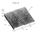
- the continuous source (whose irradiance is between 10 and 300 W / cm 2 ) leads to a densification of the material in exposed areas. This densification can, for example, be demonstrated by observing the surface of the planar guides under an atomic force field (AFM) microscope after exposure to an interference field.
- AFM atomic force field
- the impulse source comes for example from a system Lambda Physics consisting of an XeCI excimer laser pumping a laser dye lined with a BBO crystal. This impulse source drives a photoablation of the material. Fluence lower than that used would give more satisfactory results.
- Local variations in the photoinduced index are significant: typically greater than 10 -3 , preferably greater than 5. 10-3 . In some cases, this difference in photoinduced index may be greater than 10 -2 . This will be the case in particular for europium, but of course, other rare earths or mixtures of rare earths could also have the same qualities.
- the values of the induced index differences are calculated from measured diffraction efficiencies of gratings included in guides plans.
- the model used takes into account two contributions identified in the efficiency of the diffraction grating: the variation of photoinduced index of the material and the phase network created by the compaction observed under the microscope at atomic force.
- the power of the laser source must be sufficient to ensure an appropriate index variation.
- the duration of sunshine must be sufficient to ensure an appropriate index variation.
- the invention also relates to of Bragg gratings included in a waveguide as defined in the appended claims 7 and 8.
- the optical guide will have a variation in refractive index greater than or equal to 10 -3 .
- the initial proportion by mass of the welcome bath relative to the total mass of the initial bath is large enough to maintain a stable composition of the welcome bath. This proportion varies for example from 50% to 90%.
- Certain constituents of the welcome bath in particular InF 3 , MnF 2 , CdF 2 , and possibly the adjuvants, are found in small proportions in the fluorinated glass deposited.
- Zinc fluoride can be part of the welcome bath, but it is also also found, in proportions which can be relatively large (for example from 10 to 30%), in the deposited glass to which it confers increased stability.
- cerium trifluoride The preparation of cerium trifluoride is well known and presents no difficulty.
- europium difluoride Eu 2+ ion
- EuF 2 is an unstable fluoride which tends to oxidize.
- the evaporation chamber 1 is a stainless steel bell, 33 cm in diameter, with a volume of 40 liters connected by an outlet 2 via a liquid nitrogen trap to a pumping group allowing a vacuum of a few 10 -4 mbar.
- the output 2 is offset from the axis of the bell.
- a first crucible 3 in graphite containing the composition of fluorinated glass PZG and a second crucible 4 also in graphite containing the composition of lanthanide fluoride are housed in said enclosure.
- Each of these crucibles is placed on a ceramic thermocouple support rod 5, 6 respectively, and heated separately by high frequency turns 7, 8, respectively.
- a substrate 9 disposed in a heating sample holder 10 mobile fixed to an arm 17 is arranged in the common area of the cones 11 and 12 fluxes emitted respectively by the two crucibles 3 and 4.
- the optimal position crucible substrate holder is adjustable at the axis of rotation 13 of the sample holder carrying the support arm 17 of the sample holder, which can pivot and slide through the sealed watertight passage 14 located at the top of the enclosure 1. Covers, not shown, may possibly be arranged at least partially in front of the substrate.
- a third crucible 15 in graphite carbon, containing a PZG glass composition which can be different from crucible 3 which allows to create index jumps in the guide is located in such a way that the cone emission does not interfere with the emission cones of crucibles 3 and 4.
- This crucible 15 provided with high frequency heating coils 16 will allow after deposition of the PZG fluoride glass film covering the film with a coating of surface.
- the substrates used are made of CaF 2 and have a thickness of 2 to 5 mm.
- the crucible 4 contains 200 mg of CeF 3 (examples 1 and 2); 200 mg of EuF 3 -Si mixture (example 3).
- the substrate holder 10 is adjusted so that it is placed at the intersection evaporation cones for each crucible (distance between crucibles and substrates: about 10 cm).
- Evaporation lasts about 20 minutes, allowing to obtain thicknesses of a few micrometers. After evaporation, the substrate is cooled slowly (3 ° C / min), Before opening, the enclosure is filled with dry nitrogen.
- Two types of lasers were used for the study of photo-registration: a continuous source (Coherent Innova 70 ionized argon laser of 4 W doubled intracavity by a barium beta-borate crystal) and a source pulse (Lambda Physics system consisting of an XeCI excimer laser pumping a dye laser lined with a BBO crystal).
- the pulse source in the experimental conditions used, causes a photoablation of the material.
- the continuous source of lower irradiance (between 10 and 300 W / cm 2 ) leads to a densification of the material in the exposed areas. This densification was demonstrated by observation of the surface of the planar guides under an atomic force field (AFM) microscope after exposure to an interference field. It is at the origin of one of the contributions to the variation of index.
- AFM atomic force field
- FIG. 4 reproduces the experimental curves of variation of the diffraction efficiency as a function of the exposure time for the three examples.
- the differences in photoinduced index are significant: typically 5 ⁇ 10 ⁇ 3 with a cerium doping, greater than 10 ⁇ 2 with a europium doping (as indicated in Table II below).
- These induced difference in index values were calculated from the measured diffraction efficiencies of gratings inscribed in planar guides.
- the model used takes account of two identified contributions to the efficiency of the diffraction grating: the variation of photoinduced index of the material and the phase grating created by the compaction observed with an atomic force microscope (the values used are detailed in the table II).
- an optical component 19 of length 2 cm and of width 1 cm comprises a substrate 9 of thickness 2 to 5 mm coated with a layer of PZG 18 glass, thickness 1 to 10 ⁇ m
- the substrate is a material with an optical polish: fluoride glass (ZBLAN, ZBLA, BIZYbT), single crystal (CaF 2 , BaF 2 ) metal (Cu, Al).
- the coating has one of the compositions obtained in Examples 1 to 3.
- the method according to the invention therefore makes it possible to carry out optical components which exhibit a local variation of high index.
Landscapes
- Physics & Mathematics (AREA)
- Engineering & Computer Science (AREA)
- Microelectronics & Electronic Packaging (AREA)
- General Physics & Mathematics (AREA)
- Optics & Photonics (AREA)
- Glass Compositions (AREA)
Claims (8)
- Verfahren zur Herstellung von photorefraktiven Gittern vom Typ eines Bragg-Gitters in einer Wellenführung aus einem fluorierten Glas, das mit wenigstens einem Element dotiert ist, das aus der Gruppe ausgewählt ist, die aus den Ionen seltener Erden gebildet ist, wobei das dotierte fluorierte Glas lichtempfindliche Eigenschaften aufweist, d.h. eine Neigung, eine signifikante Änderung seines Brechungsindexes unter Wirkung einer. Bestrahlung mit Strahlen im Ultraviolettbereich zu erfahren, und die gewünschten Brechungsgitter in der Führung durch eine geeignete Ultraviolettbestrahlung hergestellt werden, dadurch gekennzeichnet, daß die Wellenführung eine Planarführung ist, die ein Substrat aufweist, das mit einem Film ausgestattet ist, der die Führungsschicht der Planarführung bildet, und daß das lichtempfindliche dotierte fluorierte Glas diesen Film bildet und von einem fluorierten Glas vom Typ PbF2-ZnF2-GaF2, d.h. PZG, gebildet ist, das mit einem oder mehreren der Elemente dotiert ist, die aus der Gruppe ausgewählt sind, die aus den Ionen seltener Erden gebildet ist.
- Verfahren zur Herstellung der phtorefraktiven einbeschriebenen Gitter nach Anspruch 1, dadurch gekennzeichnet, daß die Dotierelemente in dem Film in einem Verhältnis von gleich oder kleiner 10 Mol% enthalten sind.
- Verfahren zur Herstellung der photorefraktiven einbeschriebenen Gitter nach Anspruch 1, dadurch gekennzeichnet, daß die Bestrahlung mittels einer pulsierten Laserquelle realisiert wird.
- Verfahren zur Herstellung der photorefraktiven einbeschriebenen Gitter nach Anspruch 1, dadurch gekennzeichnet, daß die Bestrahlung mittels einer kontinuierlichen Laserquelle realisiert wird.
- Verfahren zur Herstellung der photorefraktiven einbeschriebenen Gitter nach einem der Ansprüche 3 oder 4, dadurch gekennzeichnet, daß die Wellenlänge der Quelle kleiner als 300 nm ist.
- Verfahren zur Herstellung der photorefraktiven einbeschriebenen Gitter nach einem der vorhergehenden Ansprüche, dadurch gekennzeichnet, daß die Dotierelemente aus der Gruppe ausgewählt sind, die aus den Ionen der seltenen Erden Ce3+, Eu2+ gebildet ist.
- Photorefraktive Gitter vom Typ eines Bragg-Gitters, die in eine Wellenführung lichteinbeschrieben sind, wie sie geeigneterweise gemäß dem Verfahren nach einem der Ansprüche 1 bis 6 erhalten werden, wobei die Wellenführung aus einem fluorierten Glas ist, das mit wenigstens einem Element dotiert ist, das aus der Gruppe ausgewählt ist, die aus den Ionen seltener Erden gebildet ist, wobei das dotierte fluorierte Glas lichtinduzierte lokale Variationen des Brechungsindexes aufweist, welche die photorefraktiven Brechungsgitter bilden, dadurch gekennzeichnet, daß die Wellenführung eine Planarführung ist, die ein Substrat umfaßt, das mit einem Film ausgestattet ist, der die Führungsschicht der Planarführung bildet, und daß das dotierte fluorierte Glas den Film bildet und durch ein fluoriertes Glas vom Typ PbF2-ZnF2-GaF2, d.h. PZG, gebildet ist, das mit einem oder mehreren der Elemente dotiert ist, die aus der besagten Gruppe ausgewählt sind, die aus den Ionen seltener Erden gebildet ist.
- Gitter nach Anspruch 7, dadurch gekennzeichnet, daß die Variation des Brechungsindexes größer oder gleich 10-3 ist.
Applications Claiming Priority (2)
| Application Number | Priority Date | Filing Date | Title |
|---|---|---|---|
| FR9514648A FR2742234B1 (fr) | 1995-12-11 | 1995-12-11 | Procede pour la realisation de reseaux de bragg a partir d'un verre fluore de type pzg et guide optique obtenu par ledit procede |
| FR9514648 | 1995-12-11 |
Publications (2)
| Publication Number | Publication Date |
|---|---|
| EP0779522A1 EP0779522A1 (de) | 1997-06-18 |
| EP0779522B1 true EP0779522B1 (de) | 2003-03-26 |
Family
ID=9485365
Family Applications (1)
| Application Number | Title | Priority Date | Filing Date |
|---|---|---|---|
| EP96402662A Expired - Lifetime EP0779522B1 (de) | 1995-12-11 | 1996-12-09 | Prozess zur Herstellung eines Bragg-Gitters in einem optischen Wellenleiter aus PZG-Fluoridglas sowie dadurch hergestelltes Bragg-Gitter |
Country Status (3)
| Country | Link |
|---|---|
| EP (1) | EP0779522B1 (de) |
| DE (1) | DE69626939T2 (de) |
| FR (1) | FR2742234B1 (de) |
Families Citing this family (1)
| Publication number | Priority date | Publication date | Assignee | Title |
|---|---|---|---|---|
| TW502133B (en) | 1999-06-10 | 2002-09-11 | Wako Pure Chem Ind Ltd | Resist composition, agent and method for reducing substrate dependence thereof |
Family Cites Families (6)
| Publication number | Priority date | Publication date | Assignee | Title |
|---|---|---|---|---|
| FR2354977A1 (fr) | 1976-06-15 | 1978-01-13 | Anvar | Compositions de verres fluores |
| FR2384724A1 (fr) | 1977-03-24 | 1978-10-20 | Anvar | Compositions de verres fluores et procede de fabrication |
| FR2643360B1 (fr) | 1989-02-02 | 1992-11-20 | Centre Nat Rech Scient | Procede de depot en phase vapeur d'un verre fluore sur un substrat, et composition vitreuse deposee ainsi obtenue |
| GB9007912D0 (en) * | 1990-04-06 | 1990-06-06 | British Telecomm | A method of forming a refractive index grating in an optical waveguide |
| FR2695943B1 (fr) * | 1992-09-18 | 1994-10-14 | Alsthom Cge Alcatel | Procédé de dépôt en phase vapeur d'un film en verre fluoré sur un substrat. |
| WO1995026519A1 (en) * | 1994-03-29 | 1995-10-05 | Monash University | A method of producing a photorefractive effect in optical devices and optical devices formed by that method |
-
1995
- 1995-12-11 FR FR9514648A patent/FR2742234B1/fr not_active Expired - Fee Related
-
1996
- 1996-12-09 DE DE69626939T patent/DE69626939T2/de not_active Expired - Fee Related
- 1996-12-09 EP EP96402662A patent/EP0779522B1/de not_active Expired - Lifetime
Non-Patent Citations (3)
| Title |
|---|
| Physical Review B, Vol.34, No.6, Septembre 1986, pages 4213-4220 * |
| Physical Review B, Vol.35, No.8, Mars 1987, pages 4109-4112 * |
| Physical Review B, Vol.39, No.9, Mars 1989, pages 6076-6081 * |
Also Published As
| Publication number | Publication date |
|---|---|
| EP0779522A1 (de) | 1997-06-18 |
| FR2742234A1 (fr) | 1997-06-13 |
| FR2742234B1 (fr) | 1998-02-27 |
| DE69626939D1 (de) | 2003-04-30 |
| DE69626939T2 (de) | 2004-02-12 |
Similar Documents
| Publication | Publication Date | Title |
|---|---|---|
| EP0588718B1 (de) | Verfahren zur Abscheidung aus der Gasphase von einem Fluorid-Glasfilm auf einem Substrat | |
| EP1347545B1 (de) | Optischer Wellenleiter mit einem verstärkenden Medium und Verfahren zu seiner Herstellung | |
| EP0196948B1 (de) | Umkehrbare Demultiplexeinrichtung von einer Mehrzahl von Lichtsignalen in integrierter Optik | |
| Norihisa Tanio et al. | Photooptical switching of polymer film waveguide containing photochromic diarylethenes | |
| Serna et al. | In situ growth of optically active erbium doped Al2O3 thin films by pulsed laser deposition | |
| EP0323317A1 (de) | Verfahren zur Herstellung von Mikro-Lichtleitern mit niedrigen optischen Ausbreitungsverlusten durch Aufbringen von Mehrfachschichten | |
| CN100365886C (zh) | 用来改善耐久性的经涂覆的光学器件 | |
| EP0086132A1 (de) | Verfahren zur Herstellung dopierten Siliziumglases für Verarbeitung von Vorformen für optische Fasern | |
| EP0543725B1 (de) | Seltene Erden enthaltende integrierte optische Komponentenstruktur, Verfahren zu ihrer Herstellung und Anwendungen | |
| EP0779522B1 (de) | Prozess zur Herstellung eines Bragg-Gitters in einem optischen Wellenleiter aus PZG-Fluoridglas sowie dadurch hergestelltes Bragg-Gitter | |
| WO2002057810A2 (fr) | Procede de fabrication d'un composant guide d'ondes a plusieurs couches empilees sur un substrat et composant guide d'ondes obtenu selon ce procede | |
| FR2676435A1 (fr) | Milieu en verre d'halogenures contenant des ions d'uranium trivalents et procede de fabrication de ce milieu. | |
| EP0456743B1 (de) | Beschichtung aus der dampfphase eines fluoridglases | |
| WO2006092536A2 (fr) | Procede de preparation d'une solution sol-gel et utilisation de cette solution pour constituer un revetement pour proteger un substrat a surface metallique | |
| FR2812664A1 (fr) | Procede de depot d'une couche de silice dopee au fluor et son application en optique ophtalmique | |
| WO2011143518A2 (en) | Glassy surface smoothing layer for integrated waveguide | |
| EP0814350B1 (de) | Vielschichtanordnung fluorierter Materialien zur Verwendung in der Optik und Verfahren zu ihrer Herstellung | |
| FR2758321A1 (fr) | Composition de verre et dispositif optique | |
| EP0579517B1 (de) | Verfahren zum Herstellen einer Vorform für optische Fasern | |
| EP0916748A1 (de) | Einkristalline Schichten aus Lanthan-Magnesium-Aluminat, Verfahren zu ihrer Herstellung durch Epitaxie aus der Flüssigphase, und optische Bauteile mit solchen Schichten | |
| EP0455551A1 (de) | Mehrlagiger Überzug für ein Polycarbonatsubstrat und Verfahren zur Herstellung von einem solchen Überzug | |
| EP0963457A1 (de) | Verfahren zum herstellen von dünnschichten aus fluoriden | |
| FR2685096A1 (fr) | Miroir optique integre et son procede de fabrication. | |
| JPS61132906A (ja) | 導波路型光素子の製造方法 | |
| Pawlewicz et al. | Improved Si-based coating materials for high power infrared lasers |
Legal Events
| Date | Code | Title | Description |
|---|---|---|---|
| PUAI | Public reference made under article 153(3) epc to a published international application that has entered the european phase |
Free format text: ORIGINAL CODE: 0009012 |
|
| AK | Designated contracting states |
Kind code of ref document: A1 Designated state(s): DE GB |
|
| 17P | Request for examination filed |
Effective date: 19971117 |
|
| 17Q | First examination report despatched |
Effective date: 20020115 |
|
| GRAG | Despatch of communication of intention to grant |
Free format text: ORIGINAL CODE: EPIDOS AGRA |
|
| RTI1 | Title (correction) |
Free format text: PROCESS FOR MANUFACTURING A BRAGG GRATING IN AN OPTICAL GUIDE MADE OF A FLUORIDE GLASS OF THE PZG TYPE AS WELL AS BRAGG GRATING THUS MANUFACTURED |
|
| GRAG | Despatch of communication of intention to grant |
Free format text: ORIGINAL CODE: EPIDOS AGRA |
|
| GRAH | Despatch of communication of intention to grant a patent |
Free format text: ORIGINAL CODE: EPIDOS IGRA |
|
| GRAH | Despatch of communication of intention to grant a patent |
Free format text: ORIGINAL CODE: EPIDOS IGRA |
|
| GRAA | (expected) grant |
Free format text: ORIGINAL CODE: 0009210 |
|
| AK | Designated contracting states |
Designated state(s): DE GB |
|
| REG | Reference to a national code |
Ref country code: GB Ref legal event code: FG4D Free format text: NOT ENGLISH |
|
| GBT | Gb: translation of ep patent filed (gb section 77(6)(a)/1977) |
Effective date: 20030326 |
|
| REF | Corresponds to: |
Ref document number: 69626939 Country of ref document: DE Date of ref document: 20030430 Kind code of ref document: P |
|
| PLBE | No opposition filed within time limit |
Free format text: ORIGINAL CODE: 0009261 |
|
| STAA | Information on the status of an ep patent application or granted ep patent |
Free format text: STATUS: NO OPPOSITION FILED WITHIN TIME LIMIT |
|
| 26N | No opposition filed |
Effective date: 20031230 |
|
| PGFP | Annual fee paid to national office [announced via postgrant information from national office to epo] |
Ref country code: GB Payment date: 20051125 Year of fee payment: 10 |
|
| PGFP | Annual fee paid to national office [announced via postgrant information from national office to epo] |
Ref country code: DE Payment date: 20051130 Year of fee payment: 10 |
|
| PG25 | Lapsed in a contracting state [announced via postgrant information from national office to epo] |
Ref country code: DE Free format text: LAPSE BECAUSE OF NON-PAYMENT OF DUE FEES Effective date: 20070703 |
|
| GBPC | Gb: european patent ceased through non-payment of renewal fee |
Effective date: 20061209 |
|
| PG25 | Lapsed in a contracting state [announced via postgrant information from national office to epo] |
Ref country code: GB Free format text: LAPSE BECAUSE OF NON-PAYMENT OF DUE FEES Effective date: 20061209 |