EP0779407B1 - Roman shade - Google Patents
Roman shade Download PDFInfo
- Publication number
- EP0779407B1 EP0779407B1 EP96308059A EP96308059A EP0779407B1 EP 0779407 B1 EP0779407 B1 EP 0779407B1 EP 96308059 A EP96308059 A EP 96308059A EP 96308059 A EP96308059 A EP 96308059A EP 0779407 B1 EP0779407 B1 EP 0779407B1
- Authority
- EP
- European Patent Office
- Prior art keywords
- sheet
- front sheets
- rear sheet
- sheets
- roman shade
- Prior art date
- Legal status (The legal status is an assumption and is not a legal conclusion. Google has not performed a legal analysis and makes no representation as to the accuracy of the status listed.)
- Expired - Lifetime
Links
Images









Classifications
-
- E—FIXED CONSTRUCTIONS
- E06—DOORS, WINDOWS, SHUTTERS, OR ROLLER BLINDS IN GENERAL; LADDERS
- E06B—FIXED OR MOVABLE CLOSURES FOR OPENINGS IN BUILDINGS, VEHICLES, FENCES OR LIKE ENCLOSURES IN GENERAL, e.g. DOORS, WINDOWS, BLINDS, GATES
- E06B9/00—Screening or protective devices for wall or similar openings, with or without operating or securing mechanisms; Closures of similar construction
- E06B9/24—Screens or other constructions affording protection against light, especially against sunshine; Similar screens for privacy or appearance; Slat blinds
- E06B9/26—Lamellar or like blinds, e.g. venetian blinds
- E06B9/262—Lamellar or like blinds, e.g. venetian blinds with flexibly-interconnected horizontal or vertical strips; Concertina blinds, i.e. upwardly folding flexible screens
-
- E—FIXED CONSTRUCTIONS
- E06—DOORS, WINDOWS, SHUTTERS, OR ROLLER BLINDS IN GENERAL; LADDERS
- E06B—FIXED OR MOVABLE CLOSURES FOR OPENINGS IN BUILDINGS, VEHICLES, FENCES OR LIKE ENCLOSURES IN GENERAL, e.g. DOORS, WINDOWS, BLINDS, GATES
- E06B9/00—Screening or protective devices for wall or similar openings, with or without operating or securing mechanisms; Closures of similar construction
- E06B9/24—Screens or other constructions affording protection against light, especially against sunshine; Similar screens for privacy or appearance; Slat blinds
- E06B9/26—Lamellar or like blinds, e.g. venetian blinds
- E06B9/264—Combinations of lamellar blinds with roller shutters, screen windows, windows, or double panes; Lamellar blinds with special devices
-
- E—FIXED CONSTRUCTIONS
- E06—DOORS, WINDOWS, SHUTTERS, OR ROLLER BLINDS IN GENERAL; LADDERS
- E06B—FIXED OR MOVABLE CLOSURES FOR OPENINGS IN BUILDINGS, VEHICLES, FENCES OR LIKE ENCLOSURES IN GENERAL, e.g. DOORS, WINDOWS, BLINDS, GATES
- E06B9/00—Screening or protective devices for wall or similar openings, with or without operating or securing mechanisms; Closures of similar construction
- E06B9/24—Screens or other constructions affording protection against light, especially against sunshine; Similar screens for privacy or appearance; Slat blinds
- E06B9/26—Lamellar or like blinds, e.g. venetian blinds
- E06B9/262—Lamellar or like blinds, e.g. venetian blinds with flexibly-interconnected horizontal or vertical strips; Concertina blinds, i.e. upwardly folding flexible screens
- E06B2009/2622—Gathered vertically; Roman, Austrian or festoon blinds
-
- E—FIXED CONSTRUCTIONS
- E06—DOORS, WINDOWS, SHUTTERS, OR ROLLER BLINDS IN GENERAL; LADDERS
- E06B—FIXED OR MOVABLE CLOSURES FOR OPENINGS IN BUILDINGS, VEHICLES, FENCES OR LIKE ENCLOSURES IN GENERAL, e.g. DOORS, WINDOWS, BLINDS, GATES
- E06B9/00—Screening or protective devices for wall or similar openings, with or without operating or securing mechanisms; Closures of similar construction
- E06B9/24—Screens or other constructions affording protection against light, especially against sunshine; Similar screens for privacy or appearance; Slat blinds
- E06B9/26—Lamellar or like blinds, e.g. venetian blinds
- E06B9/262—Lamellar or like blinds, e.g. venetian blinds with flexibly-interconnected horizontal or vertical strips; Concertina blinds, i.e. upwardly folding flexible screens
- E06B2009/2627—Cellular screens, e.g. box or honeycomb-like
Definitions
- the present invention relates to a roman shade, and more particularly, to a roman shade that allows flexibility and variety in the appearance of the shade.
- One kind of conventional roman shade is formed as a cloth hanging from a head rail, having a lower end provided with weights at given lateral intervals.
- This kind of roman shade can be raised by drawing up a raising cord or cords, forming large, loose folds in the cloth at equal vertical distances.
- Another kind of conventional shade hangs from an upper rail, but has an attached weight bar extending over the full lateral length of the lower end, and operates similarly.
- the shape or size of folds formed in the cloth as the cloth is raised are determined by the positions of the connection of the cords to the cloth, or by the shape of the cloth itself.
- the conventional roman shade allows viewing therethrough, i.e., a viewing function, if a transparent or semitransparent material is used as the cloth.
- a screening function can be provided by the shade with the use of an opaque cloth.
- the publication discloses a roman shade having an upper end of a cloth hanging from head rail, all the loops or folds of the cloth being attached to cords. Loops or folds are formed in the cloth at given vertical intervals. Front upper portions of the loops or folds are attached to a supporting cord, while rear upper portions of the loops or folds are connected to a moving cord.
- the cloth itself is semitransparent when not overlapped with another sheet of the cloth, but becomes opaque when multiple layers (i.e., formed from the loops) of the cloth are overlapped.
- the loops or folds of the cloth are overlapped.
- the loops or folds are prevented from overlapping. The loops or folds are moved by moving the moving cord relatively to the supporting cord.
- the shade disclosed in this publication uses only one cloth to provide both a viewing function and a screening function, the appearance of the cloth cannot be changed when the user desires, in that the shade cannot show more than one texture, pattern or color. Although the. overlapping condition of the cloth changes when drawn, the external appearance of the shade cannot be dramatically changed.
- One object of the invention is to overcome the disadvantages listed above by providing a shade that can change its shape, color, texture, and pattern, allowing a dramatic change in the appearance of the shade. Another object is to provide a shade having both a viewing function and a screening function, and allowing regulation of the amount of light admitted through the shade.
- a roman shade comprising a head rail, a rear sheet connected to the head rail at a upper end, a raising cord along the rear sheet extending from said head rail and connected to a lower end portion of the rear sheet, characterised in that a plurality of front sheets are arranged at predetermined vertical intervals facing said rear sheet, each of said front sheets having an attachment to a front face of said rear sheet; and an opening cord extends vertically from said head rail and is connected to each of said plurality of front sheets at a first predetermined position displaced from said attachment, said opening cord being vertically movable.
- the shade can change in appearance, including shape, color, texture, and pattern.
- a transparent or semitransparent rear sheet is used, a viewing function is obtained when the rear sheet is exposed.
- the quantity of light admitted through the shade is finely controlled according to the amount that the front sheets are opened.
- the front sheets can be made of a material different from that of the rear sheet, the appearance can be varied in two ways.
- the roman shades may include a stopper or stoppers, positioned inside the head rail, for restraining one or both (if two stoppers are provided) of the raising cord or the opening cord introduced through the stopper or stoppers to the outside of the head rail. If the pulling end of the opening cord is further introduced or drawn to the outside of the head rail, the front sheets are opened, partially exposing the rear sheet. If the pulling end of the raising cord is further introduced or drawn to the outside of the head rail, the rear sheet is raised together with the front sheets, and therefore the entire shade is raised. Both of the raising cord and opening cord may be controlled by separate stoppers.
- the roman shades may alternatively incorporate a drum or drums, positioned inside the head rail, for winding one or both (if two drums are provided) of the raising cord and the opening cord on the drum or drums, and a drum drive or drives, the drum drive(s) being externally controlled. If the pulling end of the opening cord is wound on a drum, the front sheets are opened when the drum is rotated, partially exposing the rear sheet. If the pulling end of the raising cord is wound on a drum, the rear sheet is raised together with the front sheets when the drum is rotated, and therefore the entire shade is raised. Both cords may be wound by separate drums.
- the first predetermined position on the front sheets, to which the opening cord is attached is optionally a lower end of each of the front sheets, and the opening cord is passed through each of the front sheets at a second predetermined position nearer to the attachment than the first predetermined position.
- the attached portion of the opening cord is raised, the lower end of each forward sheet is raised, exposing the rear sheet.
- Each of the front sheets forms a fold between the second predetermined position where the opening cord passes through the front sheet and the first predetermined position at a lower end of the front sheet.
- the rear sheet may be connected to the head rail at a rear portion of the head rail, in which case the raising cord extends along a front face of the rear sheet. Therefore, it is unnecessary to provide the rear sheet with a pass-through hole for introducing the raising cord from the rear face to the front face of the rear sheet.
- the absence of this pass-through hole simplifies the construction, increases the strength of the rear sheet by removing a source of abrasion damage (rubbing of raising cord on the wall of the pass-through hole).
- the roman shade may include a number of lower lateral bars corresponding to the front sheets.
- Each front sheet is attached to a corresponding lower lateral bar at a lower end portion thereof, and each lower lateral bar extends laterally across the corresponding front sheet.
- the lower lateral bar may extend across the entire front sheet or a portion thereof.
- the front sheets are raised by the opening cord to expose the rear sheet through a number of openings corresponding to the raised front sheets, and the openings vary in size depending on an amount of raising of the front sheets.
- the openings have rectilinear top edges at positions corresponding to the lower lateral bars.
- the lower lateral bar extends across the full lateral length of the front sheet, when the opening cord is drawn, the full length of the lower end portion of each front sheet is raised linearly, forming regular folds in the front sheet. If the lateral bars are extend across only a portion or portions of the lateral length of each front sheet, the portions corresponding to the lateral bars incline linearly, while the remaining portions of the front sheets form draped or wavy shapes.
- the roman shade may include a valance cloth hanging from the head rail for covering an upper end portion of the uppermost front sheet.
- Figs. 1 and 2 show a first embodiment of a roman shade according to the present invention.
- the roman shade includes a rear sheet 12 attached at an upper end thereof to a head rail 10, and hanging from the head rail 10.
- the lower end of the rear sheet 12 is connected to and weighted by a ballast bar 14.
- a plurality of cord rings 16 are attached to the rear surface 12a of the rear sheet 12, vertically distributed at positions corresponding to attached front sheets 20 (described later).
- opening cords provide both opening and closing functions
- raising cords provide both raising and lowering functions
- Raising cords 18 are connected at an anchor end thereof to the ballast bar 14, extend through the cord rings 16, and enter pass-through holes 10b of cord guides 10a attached to the lower portion of the head rail 10.
- the raising cords 18 are then introduced through a first stopper 10c provided at the right hand side of the head rail 10 (as shown in Fig. 1), and extend beyond the head rail 10.
- the remaining (pulling) ends of the raising cords 18 are all connected to a raising grip 26, which is used to draw the raising cords 18.
- the raising grip 26 is connected at its lower end to a raising return cord 28, which extends to connect to the ballast bar 14. Accordingly, the raising cords 18 can be pulled in upward or downward directions.
- Each of the front sheets 20 is connected, at an attachment along the upper end portion 20a thereof, to the rear sheet 12.
- Each individual front sheet 20 is provided with a lateral bar 24 attached to a lower end portion 20b. The lateral bars 24 extend across the full lateral length of the front sheets 20.
- Opening cords 22 extend along the full vertical length of the rear sheet 12, the opening cords 22 passing through (and movable with respect to) each of the front sheets 20 near the corresponding attachment to the back sheet 12.
- the opening cords 22 are further attached at an anchor end thereof to all of the lateral bars 24.
- any front sheet 20 is in a closed position (i.e., lowered)
- the corresponding lateral bar 24 overlaps an upper portion 20a of the next lower front sheet 20.
- each front sheet 20 forms a large, loose fold that overlaps the individual front sheets 20 immediately below, the large loose fold projecting slightly forward.
- the opening cords 22 are provided at three distributed locations along the lateral width of the front sheets 20 and rear sheet 12. Each individual opening cord 22 passes through a cord guide 10a, and is introduced through a second stopper 10d positioned at the left hand side (in Fig. 1) of the head rail 10. The opening cords then extend beyond the head rail 10, and the pulling ends 22b of each opening cord 22 are connected to an opening grip 30.
- the opening grip 30 is connected at a lower end thereof to a opening return cord 32, which is further connected to the ballast bar 14. Accordingly, the opening cords 22 can be pulled in upward or downward directions.
- Fig. 1 shows the first embodiment of a roman shade in a position where the front sheets 20 are closed, i.e., the large, loose fold of each front sheet 20 is positioned such that the corresponding lateral bar 24 is at its lowest position.
- the front sheets 20 may be opened (i.e., raised) by pulling down on the opening grip 30, thereby drawing down the pulling ends 22b (the portions extending beyond the head rail 10) of the opening cords 22, at the same time drawing up the anchor ends 22a (the portions underneath the head rail 10) of the opening cords 22.
- the opening of the front sheets 20 forms an opening 21 between a lower end portion of the fold in each front sheet 20 and the upper end portion of the next lower front sheet 20, and between the lower end portion of the fold in the lowermost front sheet 20 and the ballast bar 14. Consequently, the rear sheet 12 is exposed through the openings 21.
- the front sheets 20 can be maintained in their opened positions by preventing the movement of the opening cords 22 using the second stopper 10d.
- the second stopper 10d is released by moving the opening cords 22 with the opening grip 30.
- the anchor ends 22a of the opening cords 22 are thereby lowered to their lowermost positions by the free weight of the lateral bars 24 attached to the lower ends of the front sheets 20, returning to the state shown in Fig. 1.
- the descent of the front sheets can be stopped at any position using the second stopper 10d.
- the raising knob 26 is pulled down, thereby drawing a pulling end of the raising cords 18 down and an anchor end of the raising cords 18 up.
- the ballast bar 14 is raised, forming a series of folds in the rear sheet 12.
- the lowermost cord ring 16 is raised together with the weight bar 14, forming a fold in the rear sheet 12 between the lowermost cord ring 16 and the ballast bar 14.
- the ballast bar 14 is drawn up further, forming successive folds at each cord ring 16, eventually the entire rear sheet 12 is raised up in successive folds formed between successive cord rings 16.
- the cord rings 16 on the rear sheet 12 and the upper end portions 20a of the front sheets 20 enter positions toward the rear of the folded assembly. Meanwhile, regular folds project forward over the full lateral length of the rear sheet 12 as the rear sheet 12 is raised.
- openings 21 are formed between each front sheet 20 and the next lower front sheet 20, and between the lowermost front sheet 20 and the ballast bar 14. Consequently, the rear sheet 12 is exposed through the openings 21, and the shade can change in appearance, including shape, color, texture, and pattern.
- the roman shade according to the first embodiment allows an operator to obtain a view through the rear sheet 12 and the openings 21.
- the raising or lowering of the rear sheet 12 (and the entire shade) can be stopped at any position using the first stopper 10c, and the opening and closing of the front sheets 20 can be stopped at any position using the second stopper 10d.
- the quantity of light transmitted through the rear sheet 12 and the roman shade (overall) can be finely regulated by controlling the extent to which the front sheets 20 are drawn up. Accordingly, the regulation of light transmission is also possible.
- Fig. 6 shows a second embodiment of a roman shade according to the present invention.
- the second embodiment has the same general structure as the first embodiment, exceptions including that the front sheets 74 are formed from an expandable material, and that upper lateral bars 76 are provided at upper end portions 74a of the front sheets 74.
- the upper lateral bars 76 extend over the full lateral length of the front sheets 74.
- left and right lower corners of 70c and 70d of each of the front sheets 74 are connected to the rear sheet 12.
- only one opening cord 22 is provided in the middle position of the front sheets 74 in the lateral direction. With this structure, the middle portion of each front sheets 74 may be drawn up while leaving the left and right end portions of the front sheets 74 in a lower position.
- Fig. 6 shows a fully closed position of the front sheets 74 of the second embodiment.
- the same general operation as in the first embodiment is performed.
- both lower corners 74c and 74d of the front sheet 74 remain connected to the rear sheet 12.
- the rear sheet 12 is made of expandable material, the lower end portions 74b of the front sheets 74 are raised up in the center thereof, stretching the front sheets 74 and forming triangular openings 78 having an apex in the middle of front sheets 74 in the lateral direction.
- the triangular openings 78 are formed between a lower end portion 74b of each front sheet 74 and the upper portion of the next lower front sheet 74. Accordingly, the rear sheet 12 is exposed through the triangular openings 78, and the shade can change in appearance, including shape, color, texture, and pattern. When using a rear sheet 12 made of transparent or semitransparent material, a viewer can see through the triangular openings 78.
- the same operation as in the first embodiment is performed in order to return the front sheets 74 to the stage shown in Fig. 6.
- raising the rear sheet 12 i.e., raising the shade
- the same operation as in the first embodiment is performed. Accordingly, the raising or lowering of the rear sheet 12 (and the entire shade) can be stopped at any position using the first stopper 10c, and the opening and closing of the front sheets 74 can be stopped at any position using the second stopper 10d.
- the roman shade according to the second embodiment may be constructed with an alternative structure wherein the lower lateral corners (side end portions 74c and 74d) are not connected to the rear sheet 12.
- the expandable material may be of any kind, including resilient, pleated, or having concertina folds.
- the front sheets 74 are preferably made of an expandable material, the material of the front sheet 74 is not necessarily restricted to an expandable type.
- upper lateral bars 76 are attached to upper end portions 74a of the front sheets 74, the upper end portions 74a of the front sheets may alternatively be attached directly to the rear sheet 12.
- Fig. 8 shows a third embodiment of a roman shade according to the present invention.
- the third embodiment has the same general structure as the first embodiment, exceptions including that left and right lateral bars 82 and 84 are attached to left and right lower end portions 80b of front sheets 80.
- the left and right lateral bars 82 and 84 each extend laterally from respective left and right edges toward the center of a corresponding front sheet 80, leaving a draping central portion.
- the inner ends of the left and right lateral bars 82 and 84 are connected to opening cords 22 as shown in Fig. 8. Each central portion drapes down by the virtue of the empty weight of the corresponding front sheet 80.
- Fig. 8 shows the closed state of the front sheets 80.
- Anchor ends of the opening cords 22 are attached to the inner ends of left and right lateral bars 82 and 84, and when the anchor ends of the opening cords 22 are drawn up, the left and right lateral bars 82 and 84 incline upward.
- the left and right portions of the corresponding front sheets 80 follow and incline linearly upward.
- the front sheets 80 unattached to the left and right lateral bars 82 and 84 in the middle region, form hanging portions in the center of the front sheets 80.
- the left and right portions of the front sheets 80 attached to and supported by the left and right lateral bars 82 and 84, form inclined straight edges as the front sheets are pulled up by the opening cords 22, while the unattached middle portions form curved (draping) portions when pulled up by the opening cords 22.
- an opening 86 having a draped shape is formed between the lower end portion 80b of each front sheet 80 and the upper end portion 80a of the next lower front sheet 80, and between a lower end portion 80b of the lowermost front sheet 80 and the ballast bar 14.
- the rear sheet 12 is exposed through the openings 86. Accordingly, the shade can change in appearance, including shape, color, texture, and pattern.
- a viewer can see through the triangular openings 86.
- the same operation as in the first embodiment is performed in order to return the front sheets 86 to the stage shown in Fig. 8.
- raising the rear sheet 12 i.e., raising the shade
- the same operation as in the first embodiment is performed. Accordingly, the raising or lowering of the rear sheet 12 (and the entire shade) can be stopped at any position using the first stopper 10c, and the opening and closing of the front sheets 80 can be stopped at any position using the second stopper 10d.
- Fig. 10 shows an fourth embodiment of a roman shade according to the present invention.
- the fourth embodiment has the same general structure as the third embodiment, exceptions including that lateral bars are not provided toward lower end portions 90b of the front sheets 90, and that both side end portions of each front sheet 90 are sewn to both side end portions of the rear sheet 12.
- each sewn side end portion of each front sheet 90 includes a slack portion 90d where the side end portion is sewn to the rear sheet 12.
- the opening cords 22 are attached to the front sheets 90 only at central portions thereof. More particularly, a plurality of opening cords 22 are preferably attached to the front sheets 90 within a range of laterally central positions away from the side end portions, with lateral spacing therebetween.
- Fig. 10 shows the fourth embodiment of the present invention of a roman shade with the front sheets 90 in a closed (i.e., lowered) position.
- the same general action as in the third embodiment is taken. That is, as the anchor ends of the opening cords 22 are drawn up to open the front sheets 90.
- the opening cords 22 are attached to the front sheets 90 only at the central portions thereof, and the front sheets 90 are sewn at the edges of the rear sheet 12, large draped openings 92 are formed.
- Each draped opening 92 is bounded at the top edge by wavy draping portions of the corresponding front sheet 92.
- the slack portions 90d at the edges of each of the front sheets 90 are taken up by the opening action.
- a draped opening 92 is formed between a lower end portion 90b of each front sheet 90 and an upper end portion 90a of the next lower front sheet 90, and between a lower end portion 90b of the lowermost front sheet 90 and the ballast bar 14.
- the rear sheet 12 is exposed through the draped openings 92, and the shade can change in appearance, including shape, color, texture, and pattern.
- a transparent or semitransparent material is used to form the rear sheet 12, a view is obtained through the openings 92.
- the same operation as in the first embodiment is performed, returning the front sheets 20 to the state shown in Fig. 12.
- the same operation as in the first embodiment is performed. Accordingly, the raising or lowering of the rear sheet 12 (and the entire shade) can be stopped at any position using the first stopper 10c, and the opening and closing of the front sheets 90 can be stopped at any position using the second stopper 10d.
- Fig. 13 shows a fifth embodiment of a roman shade according to the present invention.
- the fifth embodiment has the same general structure as the first embodiment, exceptions including that the front sheets 100 do not extend vertically across the full separation between successive front sheets 100. Accordingly, in the stage where the front sheets 100 have been fully lowered, the lateral bar 24 provided at the lower end portion 100b of each front sheet 100 remains separated from the next lower front sheet 100.
- the openings 102 between the front sheets 100 are variable in size, but are always open to some degree.
- An opening 102 is formed between the lower end portion of each upper front sheet 100 and the upper end portion 100a of the next lower front sheet 100, and between the lower end portion of the lowermost front sheet 100 and the ballast bar 14. In this fashion, the rear sheet 12 is always exposed through the openings 102.
- Fig. 13 shows the fully lowered condition of the front sheets 100 of the fifth embodiment.
- the vertical length of each front sheet 100 is approximately half of the length of the front sheet in the first embodiment and approximately half of the vertical distance between successive front sheets 100.
- the opening amount of the fully lowered front sheets 100 (i.e., the size of the openings 102) in the fifth embodiment is approximately half the length of the distance between front sheets 100.
- the same actions as in the first embodiment are taken. That is, as the anchor ends 22a are drawn up, the front sheets 100 are opened. However, since the openings 102 are always present, when raising the front sheets 100 from the stage shown in Fig. 13, the openings 102 become wider.
- the lateral bars 24 are brought into contact to the upper end portions 100a of the front: sheets 100, and the lateral bars 24 are thereby restrained from being raised any further.
- the vertical length of each front sheet 100 becomes one half of that shown in Fig. 13. Therefore, the size of the openings 102 is increased to approximately three fourths the length of the vertical distance between the front sheets 100, and the rear sheet 12 is exposed to a larger extent than that of the fully closable front sheet of the first embodiment. Accordingly, the shade can change in appearance, including shape, color, texture, and pattern.
- a transparent or semitransparent material is used to form the rear sheet 12, a view is obtained through the openings 98.
- the regulation of the quantity of light admitted through the openings 102 is possible. That is, the roman shade of the fifth embodiment can be used to regulate the amount of light admitted therethrough.
- the same operation as in the first embodiment is performed, returning the front sheets 100 to the state shown in Fig. 13.
- the same operation as in the first embodiment is performed. Accordingly, the raising or lowering of the rear sheet 12 (and the entire shade) can be stopped at any position using the first stopper 10c, and the opening and closing of the front sheets 100 can be stopped at any position using the second stopper 10d.
- Figs. 15 and 16 show a sixth embodiment of a roman shade according to the present invention.
- upper ends 114a (attachments) of a plurality of front sheets 114 are attached at predetermined vertical intervals to a rear sheet 110 hanging from a head rail 110.
- the upper ends 114a of the front sheets 114 are attached to the front face 110b of the rear sheet 110.
- the rear sheet 110 hangs via its upper end 110a from a rear portion 112a of a head rail 112.
- the lower end 110c of the rear sheet 110 is attached to a ballast bar 116.
- the attachments at upper ends 114a of the front sheets 114 to the rear sheet 110 are formed with insertion extensions 113, through which opening cords 118 and raising cords 124 can be passed.
- the insertion extensions 113 are provided at equal intervals in the lateral direction at three places along the lateral length of each front sheet 114.
- each individual front sheet 114 The inner surfaces of the lower ends 114b of each individual front sheet 114 are connected to shaping plates 117 extending over the full lateral length of each individual front sheet 114.
- the shaping plates 117 shape the lower end of the fold of each opened front sheet 114 to a rectangular shape.
- Anchor ends of the opening cords 118 extend from the head rail 112 in the vertical direction, and are connected to each of the front sheets 114.
- the opening cords 118 are passed through the insertion extensions 113 between the upper portion of each front sheets 114 and the rear sheet 110.
- the opening cords 118 are further passed through pass-through holes 112c of cord guides 112b at the lower side of the head rail 112, and through a stopper 112d positioned at the left end (in Fig. 17) of the head rail 112.
- Opening cords 118 Pulling ends of the opening cords 118 extend beyond the head rail 112. The pulling ends of the opening cords 118 are then connected to an opening grip 120.
- An opening return cord is connected to the lower portion of the opening grip 120, and the opening return cord extends to connect to the ballast bar 116. Accordingly, the opening cords 118 can be pulled in upward or downward directions.
- Anchor ends of the raising cords 124 extend from the lower portion of the head rail 112, are passed through the insertion extensions 113 between the rear sheet 110 and the upper portions of the front sheets 114, and are connected to the ballast bar 116. Furthermore, pulling ends of the raising cords 124 are wound on a drum 126 (or plurality of drums 126, only one drum 126 being shown).
- the drum 126 is mounted within the head rail 112, and is rotatable via a rotation axis 128 at the center of the drum 126.
- the rotation axis 128 is rotatably supported within the head rail 112. A left end portion of the rotation axis 128 (as shown in Fig.
- a ball-chain 130 is wound about the pulley and engaged thereto, so that the pulley is driven in forward or reverse directions by operating the ball-chain 130.
- An upper end 132a of a valance cloth 132 is connected to a front side 112e of the head rail 112.
- the valance cloth 132 hangs from the head rail 112, and extends midway between the upper end portion and lower end portion of the uppermost front sheet 114.
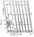
- Fig. 15 shows the closed position of the front sheets 114 of the sixth embodiment.
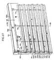
- the opening grip 120 (or the opening cord 118 itself) is pulled down, drawing up the anchor ends of the opening cords 118.
- the lower ends 114b of each front sheet 114 are raised, forming a linear sharp fold over the entire lateral width of each front sheets 114.
- the linear sharp folds follow influence of the shaping plates 117, forming rectangular openings 134 between the sharp fold in each front sheet 114 and the upper end portion 114a of the next lower front sheet 114, and between the sharp fold in the lowermost front sheet 114 and the ballast bar 116.
- the rear sheet 110 is exposed through the rectangular openings 134.
- the front sheets 114 can be held in open and closed positions (or any position in between) by fastening the stopper 112d to restrain the opening cords 118 from moving. Accordingly, the shade can change in appearance, including shape, color, texture, and pattern.
- a view can be obtained through the rear sheet 110 as seen through the openings 134.
- the quantity of light admitted through the rear sheet 110 can be finely controlled by controlling the extent to which the front sheets 114 are drawn up, and the amount of light admitted can be regulated thereby.
- the opening cords 118 are moved, using the opening grip 120 or the opening cords 118 themselves, to release the stopper 112d, and allowing the opening cords 118 to move vertically. In this manner, the opening cords 118 and front sheets 114 are lowered to the lowermost position (closed) under the weight of the shaping plates 117, returning to the position shown in Figs. 15 and 16.
- the opening and closing of the front sheets 94 can be stopped at any position using the stopper 112d if one desires to fix the front sheets 114 in another position, e.g., in a halfway position. Therefore, as the rear sheet 110 is exposed through the openings 144, the shade can change in appearance, including shape, color, texture, and pattern. Furthermore, when a transparent or semitransparent material is used to form the rear sheet 110, a view is obtained through the openings 144.
- the pulley In order to raise the rear sheet 10 (i.e., to raise the shade), the pulley is driven in a winding (raising) direction of the raising cords 124 by operating the ball-chain 130.
- the anchor end portions of the raising cords 124 are thereby wound on the drum 124.
- the anchor end portions of the raising cords 124 are drawn up, while the ballast bar 116 is raised together with the anchor end portions.
- the ballast bar 116 is drawn into contact with the upper end 114 of the lowermost front sheet 114, the attachments to the front sheets (adjacent to one another in the vertical direction) are brought in order into contact with one another, forming regular folds between the attachments.
- the folds in the rear sheet 110 extend over the full lateral width of the rear sheet 110 and project backwards. Accordingly, as shown in Fig. 19, the front sheets 114 are raised together (forming folds projecting forwards) with the rear sheet 110. That is, the shade is raised. Since the back rear sheet 110 and the front sheets 114 do not lie upon one another, they are not bulky, and the front sheets 114 can be folded neatly.
- the raising cords 124 are unwound (lowered) from the drum 126. Consequently, the ballast bar 116 is lowered under its own weight, and the rear sheet 110 is lowered in a stepwise fashion, the folds unfolding in order from the bottom of the rear sheet. In this manner, the front sheets 114 are also lowered and unfolding in order from the lowermost front sheet 114.
- the raising or lowering of the rear sheet 110 (and the entire shade) can be stopped at any position using the ball-chain 130, and the opening and closing of the front sheets 114 can be stopped at any position using the stopper 112d.
- Fig. 20 shows a seventh embodiment of a roman shade according to the present invention.
- the seventh embodiment has the same general structure as the sixth embodiment, exceptions including that left and right lateral bars 140 and 142 are attached to the lower ends 114b of the front sheets 114, and extend from both left and right side end portions of each individual front sheet 114 towards the center thereof.
- the inner end portions of the left and right lateral bars 140 and 142 are attached to the opening cords 118.
- one of the opening cords 118 is preferably attached to the center portion of each front sheet 140, giving a total of three opening cords 118.
- the opening action of the front sheets 114 and the raising action of the rear sheet 110 are performed in a manner similar to that of the sixth embodiment.
- the left and right lateral bars 140 and 142 are attached to the opening cords 118, but do not extend across the full lateral width of the front sheets 114, when the front sheets 114 are raised, the left and right lateral bars 140 and 142 incline linearly upward as shown in Fig. 20.
- the unsupported portions of the center of the front sheets 114 form draped wave-like shapes along the lateral direction.
- draped openings 144 having a draped shape including straight lines and curves are formed between the lower end portion 114b of each front sheet 114 and the upper end 114a of the next lower front sheet 114, and between the lower end portion 114d of the lowermost front sheet 114 and the ballast bar 116. Therefore, as the rear sheet 110 is exposed through the openings 144, the shade can change in appearance, including shape, color, texture, and pattern. Furthermore, when a transparent or semitransparent material is used to form the rear sheet 110, a view is obtained through the openings 144.
- the same operation as in the sixth embodiment is performed, returning the front sheets 114 to the closed state (not shown).
- the same operation as in the sixth embodiment is performed. Accordingly, the raising or lowering of the rear sheet 110 (and the entire shade) can be stopped at any position using the ball-chain 130, and the opening and closing of the front sheets 114 can be stopped at any position using the stopper 112d.
- Fig. 21 shows an eighth embodiment of a roman shade according to the present invention.
- the eighth embodiment has the same general structure as the sixth embodiment, exceptions including that four lateral bars 150, 152, 154, and 156 are arranged in series and attached to the lower ends 114b of the front sheets 114.
- the opening cords 118 are preferably joined to the front sheets 114 at points where the first two lateral bars 150 and 152 meet, and where the second two lateral bars 154 and 156 meet. Accordingly, when the opening cords are drawn up, the front sheets 114 are drawn up in a jagged shape formed from straight lines.
- the opening action of the front sheets 114 and the raising action of the rear sheet 110 are performed in a manner similar to that of the sixth embodiment.
- the four lateral bars 150, 152, 154, and 156 are arranged in series, and the opening cords 118 are joined to the front sheets 114 at points where successive lateral bars 150, 152 and 154, 156 meet, when the front sheets 114 are raised, all four lateral bars 150, 152, 154, 156 incline linearly upward as shown in Fig. 21. That is, from the viewpoint of Fig.
- the lateral bars 150 incline linearly upward to the right
- the lateral bars 152 incline linearly downward to the right
- the lateral bars 154 incline linearly upward to the right
- the lateral bars 156 incline linearly downward to the right.
- the front sheets 114 form a jagged shape along the lateral direction.
- jagged openings 158 having a jagged shape made of straight lines (i.e., having a waveform of straight lines) are formed between the lower end portion 114b of each front sheet 114 and the upper end 114a of the next lower front sheet 114, and between the lower end portion 114d of the lowermost front sheet 114 and the ballast bar 116. Therefore, as the rear sheet 110 is exposed through the openings 158, the shade can change in appearance, including shape, color, texture, and pattern. Furthermore, when a transparent or semitransparent material is used to form the rear sheet 110, a view is obtained through the openings 158.
- the same operation as in the sixth embodiment is performed, returning the front sheets 114 to the closed state (not shown).
- the same operation as in the sixth embodiment is performed. Accordingly, the raising or lowering of the rear sheet 110 (and the entire shade) can be stopped at any position using the ball-chain 130, and the opening and closing of the front sheets 114 can be stopped at any position using the stopper 112d.
- the opening cords 118 and raising cords 124 are passed through insertion extensions 113 between the rear sheet 110 and front sheets 114.
- an alternative structure may use pass-through holes formed near the connections of the rear sheet 110 and front sheets 114 instead of the insertion extensions, wherein the opening cords 118 and raising cords 124 are passed through the pass-through holes.
- the opening cords 118 are not passed through the front sheets 114 or rear sheet 110, but are hung in front of the front sheets 114 and attached thereto.
- the rear sheet 110 in attached to the rear portion 112a of the head rail 112, the rear sheet 110 may be alternatively attached to the front side 112e of the head rail 112.
- pass-through holes are preferably formed in the rear sheet 110 at suitable portions thereof, so that the opening cords 118 and raising cords 124 can be passed through the pass-through holes and in front of the rear sheet 110.
- the raising cords 124 are wound on the drum 126 and the opening cords 118 are controlled through the stopper 112d and opening grip 120, the present invention is not restricted to this structure.
- the opening cords 118 may be wound on a drum and the raising cords 124 controlled by a stopper and grip.
- both cords 118 and 124 may be on drums, or both cords may be provided with respective stoppers and grips.
- connection of the front sheets and opening cords may be formed by sewing the opening cords directly to the front sheets.
- connection rings may be attached to the front sheets or lateral bars (if present), and the opening cords may be connected to or sewn to the connection rings.
- the front sheets and rear sheet may be formed from materials, colors, or patterns differing from one another, allowing the selection of more than one kind of sheet per shade.
- the front sheets are operable by the opening grip or the opening cord itself, while the rear sheets are operable by the raising grip or the raising cord itself.
- the grips are not provided.
- the head rail in several embodiments includes a system including cord guides for controlling the raising cords and opening cords and for introducing the pulling ends of the cords beyond the end of the head rail, stoppers for restraining the cords, and grips for operating the cords
- the present invention is not restricted to this particular structure.
- a system may be alternatively provided in which a drum is provided at or within the head rail, one or both of the raising cords or the opening cords being wound on the drum for winding and rewinding.
- One end of a rotation axis rotating with the drum can be provided with a pulley so that the winding of the drum is controlled with a control chain.
- front sheets are commonly connected to opening cords
- the invention may be alternatively structured such that sets of opening cords control different sets of front sheets.
- sets of adjacent front sheets may be controlled with corresponding sets of opening cords, or sets of alternating front sheets may be controlled with corresponding sets of opening cords.
- a set of front sheets that is not connected to opening cords may be formed.
- each of the described embodiments of the invention by exposing a rear sheet having any appearance, allows a dramatic change in the appearance of the shade. If the rear. sheet is transparent, semitransparent, or provided in strips, a viewing function and a screening function are provided, and the amount of light admitted through the front sheets of shade can be regulated.
- the shade may be fully or partially raised and lowered, while the front sheets may be fully or partially opened or closed.
Landscapes
- Engineering & Computer Science (AREA)
- Structural Engineering (AREA)
- Architecture (AREA)
- Civil Engineering (AREA)
- Curtains And Furnishings For Windows Or Doors (AREA)
Description
- The present invention relates to a roman shade, and more particularly, to a roman shade that allows flexibility and variety in the appearance of the shade.
- One kind of conventional roman shade is formed as a cloth hanging from a head rail, having a lower end provided with weights at given lateral intervals. This kind of roman shade can be raised by drawing up a raising cord or cords, forming large, loose folds in the cloth at equal vertical distances.
- Another kind of conventional shade hangs from an upper rail, but has an attached weight bar extending over the full lateral length of the lower end, and operates similarly.
- In these conventional roman shades, the shape or size of folds formed in the cloth as the cloth is raised are determined by the positions of the connection of the cords to the cloth, or by the shape of the cloth itself. The conventional roman shade allows viewing therethrough, i.e., a viewing function, if a transparent or semitransparent material is used as the cloth. Alternatively, a screening function can be provided by the shade with the use of an opaque cloth.
- However, with the known roman shades, the appearance of the cloth is the same each time it is raised, i.e., the roman shade cannot form different shapes. Furthermore, if one desires to obtain both a viewing function and a screening function, two roman shades, one made of semitransparent cloth and a one made of opaque cloth, must be used simultaneously. Still further, in order to control the quantity of the light admitted to a room by the conventional roman shade, one can only raise the shade itself. Fine control of the quantity of light admitted is impossible.
- One known shade allowing both a viewing function and a screening function is disclosed in commonly assigned Japanese Patent Publication HEI 7-39449. The publication discloses a roman shade having an upper end of a cloth hanging from head rail, all the loops or folds of the cloth being attached to cords. Loops or folds are formed in the cloth at given vertical intervals. Front upper portions of the loops or folds are attached to a supporting cord, while rear upper portions of the loops or folds are connected to a moving cord. The cloth itself is semitransparent when not overlapped with another sheet of the cloth, but becomes opaque when multiple layers (i.e., formed from the loops) of the cloth are overlapped. In order to provide a screening function, the loops or folds of the cloth are overlapped. In order to provide a viewing function, the loops or folds are prevented from overlapping. The loops or folds are moved by moving the moving cord relatively to the supporting cord.
- However, since the shade disclosed in this publication uses only one cloth to provide both a viewing function and a screening function, the appearance of the cloth cannot be changed when the user desires, in that the shade cannot show more than one texture, pattern or color. Although the. overlapping condition of the cloth changes when drawn, the external appearance of the shade cannot be dramatically changed.
- One object of the invention is to overcome the disadvantages listed above by providing a shade that can change its shape, color, texture, and pattern, allowing a dramatic change in the appearance of the shade. Another object is to provide a shade having both a viewing function and a screening function, and allowing regulation of the amount of light admitted through the shade.
- The above objects are attained by providing, according to one aspect of the present invention, a roman shade, comprising a head rail, a rear sheet connected to the head rail at a upper end, a raising cord along the rear sheet extending from said head rail and connected to a lower end portion of the rear sheet, characterised in that a plurality of front sheets are arranged at predetermined vertical intervals facing said rear sheet, each of said front sheets having an attachment to a front face of said rear sheet; and an opening cord extends vertically from said head rail and is connected to each of said plurality of front sheets at a first predetermined position displaced from said attachment, said opening cord being vertically movable.
- Accordingly, in addition to the functions of a conventional roman shade, since the front sheets can be partially or fully opened by the opening cord to expose the rear sheet, the shade can change in appearance, including shape, color, texture, and pattern. When a transparent or semitransparent rear sheet is used, a viewing function is obtained when the rear sheet is exposed. Furthermore, the quantity of light admitted through the shade is finely controlled according to the amount that the front sheets are opened. Still further, since the front sheets can be made of a material different from that of the rear sheet, the appearance can be varied in two ways.
- Accordingly, if viewed from the outside of a room (i.e., the back of the roman shade), no raising cords are visible, improving the external appearance of the roman shade. Still further, since the front sheets form frontward-projecting folds when raised and the rear sheet forms backward-projecting folds when raised, the front and rear sheets do not lie upon one another, so the shade is folded neatly and without bulkiness. In addition, by passing the opening cords and raising cords through the same pass-through portion, the shade is simpler to manufacture.
- The roman shades may include a stopper or stoppers, positioned inside the head rail, for restraining one or both (if two stoppers are provided) of the raising cord or the opening cord introduced through the stopper or stoppers to the outside of the head rail. If the pulling end of the opening cord is further introduced or drawn to the outside of the head rail, the front sheets are opened, partially exposing the rear sheet. If the pulling end of the raising cord is further introduced or drawn to the outside of the head rail, the rear sheet is raised together with the front sheets, and therefore the entire shade is raised. Both of the raising cord and opening cord may be controlled by separate stoppers.
- The roman shades may alternatively incorporate a drum or drums, positioned inside the head rail, for winding one or both (if two drums are provided) of the raising cord and the opening cord on the drum or drums, and a drum drive or drives, the drum drive(s) being externally controlled. If the pulling end of the opening cord is wound on a drum, the front sheets are opened when the drum is rotated, partially exposing the rear sheet. If the pulling end of the raising cord is wound on a drum, the rear sheet is raised together with the front sheets when the drum is rotated, and therefore the entire shade is raised. Both cords may be wound by separate drums.
- The first predetermined position on the front sheets, to which the opening cord is attached, is optionally a lower end of each of the front sheets, and the opening cord is passed through each of the front sheets at a second predetermined position nearer to the attachment than the first predetermined position. As the attached portion of the opening cord is raised, the lower end of each forward sheet is raised, exposing the rear sheet. Each of the front sheets forms a fold between the second predetermined position where the opening cord passes through the front sheet and the first predetermined position at a lower end of the front sheet.
- The rear sheet may be connected to the head rail at a rear portion of the head rail, in which case the raising cord extends along a front face of the rear sheet. Therefore, it is unnecessary to provide the rear sheet with a pass-through hole for introducing the raising cord from the rear face to the front face of the rear sheet. The absence of this pass-through hole simplifies the construction, increases the strength of the rear sheet by removing a source of abrasion damage (rubbing of raising cord on the wall of the pass-through hole).
- The roman shade may include a number of lower lateral bars corresponding to the front sheets. Each front sheet is attached to a corresponding lower lateral bar at a lower end portion thereof, and each lower lateral bar extends laterally across the corresponding front sheet. The lower lateral bar may extend across the entire front sheet or a portion thereof. The front sheets are raised by the opening cord to expose the rear sheet through a number of openings corresponding to the raised front sheets, and the openings vary in size depending on an amount of raising of the front sheets. The openings have rectilinear top edges at positions corresponding to the lower lateral bars. If the lower lateral bar extends across the full lateral length of the front sheet, when the opening cord is drawn, the full length of the lower end portion of each front sheet is raised linearly, forming regular folds in the front sheet. If the lateral bars are extend across only a portion or portions of the lateral length of each front sheet, the portions corresponding to the lateral bars incline linearly, while the remaining portions of the front sheets form draped or wavy shapes.
- Optionally, the roman shade may include a valance cloth hanging from the head rail for covering an upper end portion of the uppermost front sheet.
- In the accompanying drawings:
- Fig. 1 is a perspective view of a first embodiment of a roman shade according to the present invention;
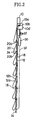
- Fig. 2 is a sectional view taken along line II-II of Fig. 1;
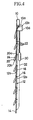
- Fig. 3 is a partially cutaway perspective view of the roman shade of Fig. 1, with the front sheets drawn up;
- Fig. 4 is a sectional view taken along line IV-IV of Fig. 3;
- Fig. 5 is a perspective view of the roman shade of Fig. 1, in which a rear sheet is raised;
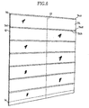
- Fig. 6 is a perspective view of a second embodiment of a roman shade according to the present invention, in which front sheets are closed;
- Fig. 7 is a perspective view of the roman shade of Fig. 6, in which front sheets are opened;
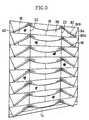
- Fig. 8 is a perspective view of a third embodiment of a roman shade according to the present invention, in which front sheets are closed;
- Fig. 9 is a perspective view of the roman shade of Fig. 8, in which front sheets are raised;
- Fig. 10 is a perspective view of a fourth embodiment of a roman shade according to the present invention, in which front sheets are closed;
- Fig. 11 is an enlarged detail of Part A of Fig. 10;
- Fig. 12 is a perspective view of the roman shade of Fig. 10, in which front sheets are raised;
- Fig. 13 is a perspective view of a fifth embodiment of a roman shade according to the present invention, in which front sheets are closed;
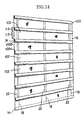
- Fig. 14 is a perspective view of the roman shade of Fig. 13, in which front sheets are open;
- Fig. 15 is a partially cutaway perspective view of a sixth embodiment of a roman shade according to the present invention;
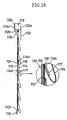
- Fig. 16 is a sectional view taken along line XXXI-XXXI of Fig. 15;
- Fig. 17 is a perspective view of a sixth embodiment of a roman shade according to the present invention, in which front sheets are open;
- Fig. 18 is a sectional view taken along line XXXIII-XXXIII of Fig. 17;
- Fig. 19 is a perspective view of the roman shade of Fig. 17, in which a rear sheet is raised;
- Fig. 20 is a perspective of a seventh embodiment of a roman shade according to the present invention;
- Fig. 21 is a perspective view of an eighth embodiment of a roman shade according to the present invention;
-
- Figs. 1 and 2 show a first embodiment of a roman shade according to the present invention. As shown in Fig. 1, the roman shade includes a
rear sheet 12 attached at an upper end thereof to ahead rail 10, and hanging from thehead rail 10. The lower end of therear sheet 12 is connected to and weighted by aballast bar 14. A plurality of cord rings 16 are attached to therear surface 12a of therear sheet 12, vertically distributed at positions corresponding to attached front sheets 20 (described later). - As hereinafter described, "opening cords" provide both opening and closing functions, and "raising cords" provide both raising and lowering functions.
- Raising
cords 18 are connected at an anchor end thereof to theballast bar 14, extend through the cord rings 16, and enter pass-throughholes 10b of cord guides 10a attached to the lower portion of thehead rail 10. The raisingcords 18 are then introduced through afirst stopper 10c provided at the right hand side of the head rail 10 (as shown in Fig. 1), and extend beyond thehead rail 10. The remaining (pulling) ends of the raisingcords 18 are all connected to a raisinggrip 26, which is used to draw the raisingcords 18. The raisinggrip 26 is connected at its lower end to a raisingreturn cord 28, which extends to connect to theballast bar 14. Accordingly, the raisingcords 18 can be pulled in upward or downward directions. - A plurality of
front sheets 20, which extend across the full lateral length of therear sheet 12, are evenly vertically distributed on the front face of therear sheet 12. Each of thefront sheets 20 is connected, at an attachment along theupper end portion 20a thereof, to therear sheet 12. Eachindividual front sheet 20 is provided with alateral bar 24 attached to alower end portion 20b. The lateral bars 24 extend across the full lateral length of thefront sheets 20. -
Opening cords 22 extend along the full vertical length of therear sheet 12, the openingcords 22 passing through (and movable with respect to) each of thefront sheets 20 near the corresponding attachment to theback sheet 12. The openingcords 22 are further attached at an anchor end thereof to all of the lateral bars 24. When anyfront sheet 20 is in a closed position (i.e., lowered), the correspondinglateral bar 24 overlaps anupper portion 20a of the next lowerfront sheet 20. In this manner, eachfront sheet 20 forms a large, loose fold that overlaps theindividual front sheets 20 immediately below, the large loose fold projecting slightly forward. - The opening
cords 22 are provided at three distributed locations along the lateral width of thefront sheets 20 andrear sheet 12. Eachindividual opening cord 22 passes through acord guide 10a, and is introduced through asecond stopper 10d positioned at the left hand side (in Fig. 1) of thehead rail 10. The opening cords then extend beyond thehead rail 10, and the pulling ends 22b of eachopening cord 22 are connected to anopening grip 30. The openinggrip 30 is connected at a lower end thereof to aopening return cord 32, which is further connected to theballast bar 14. Accordingly, the openingcords 22 can be pulled in upward or downward directions. - Fig. 1 shows the first embodiment of a roman shade in a position where the
front sheets 20 are closed, i.e., the large, loose fold of eachfront sheet 20 is positioned such that the correspondinglateral bar 24 is at its lowest position. As shown in Fig. 1, thefront sheets 20 may be opened (i.e., raised) by pulling down on theopening grip 30, thereby drawing down the pulling ends 22b (the portions extending beyond the head rail 10) of the openingcords 22, at the same time drawing up the anchor ends 22a (the portions underneath the head rail 10) of the openingcords 22. The opening of thefront sheets 20 forms anopening 21 between a lower end portion of the fold in eachfront sheet 20 and the upper end portion of the next lowerfront sheet 20, and between the lower end portion of the fold in thelowermost front sheet 20 and theballast bar 14. Consequently, therear sheet 12 is exposed through theopenings 21. Thefront sheets 20 can be maintained in their opened positions by preventing the movement of the openingcords 22 using thesecond stopper 10d. - In order to open the
front sheets 22 from a closed position, thesecond stopper 10d is released by moving the openingcords 22 with the openinggrip 30. The anchor ends 22a of the openingcords 22 are thereby lowered to their lowermost positions by the free weight of the lateral bars 24 attached to the lower ends of thefront sheets 20, returning to the state shown in Fig. 1. Optionally, the descent of the front sheets can be stopped at any position using thesecond stopper 10d. - In order to raise the rear sheet 12 (together with the
front sheets 20, i.e., raising the entire shade), the raisingknob 26 is pulled down, thereby drawing a pulling end of the raisingcords 18 down and an anchor end of the raisingcords 18 up. In this manner, theballast bar 14 is raised, forming a series of folds in therear sheet 12. As theballast bar 14 is brought into contact with thelowermost cord ring 16, thelowermost cord ring 16 is raised together with theweight bar 14, forming a fold in therear sheet 12 between thelowermost cord ring 16 and theballast bar 14. As theballast bar 14 is drawn up further, forming successive folds at eachcord ring 16, eventually the entirerear sheet 12 is raised up in successive folds formed between successive cord rings 16. Since theupper end portions 20a of thefront sheets 20 are attached to theback sheet 12 at positions corresponding to the positions of the cord rings 16 (as shown in Fig. 5), the cord rings 16 on therear sheet 12 and theupper end portions 20a of thefront sheets 20 enter positions toward the rear of the folded assembly. Meanwhile, regular folds project forward over the full lateral length of therear sheet 12 as therear sheet 12 is raised. - As described, by drawing down the pulling ends 22b and drawing up the anchor ends 22a of the opening
cords 22,openings 21 are formed between eachfront sheet 20 and the next lowerfront sheet 20, and between thelowermost front sheet 20 and theballast bar 14. Consequently, therear sheet 12 is exposed through theopenings 21, and the shade can change in appearance, including shape, color, texture, and pattern. - Furthermore, by using a
rear sheet 12 made of transparent or semitransparent material, the roman shade according to the first embodiment allows an operator to obtain a view through therear sheet 12 and theopenings 21. The raising or lowering of the rear sheet 12 (and the entire shade) can be stopped at any position using thefirst stopper 10c, and the opening and closing of thefront sheets 20 can be stopped at any position using thesecond stopper 10d. Still further, the quantity of light transmitted through therear sheet 12 and the roman shade (overall) can be finely regulated by controlling the extent to which thefront sheets 20 are drawn up. Accordingly, the regulation of light transmission is also possible. - Fig. 6 shows a second embodiment of a roman shade according to the present invention. The second embodiment has the same general structure as the first embodiment, exceptions including that the
front sheets 74 are formed from an expandable material, and that upper lateral bars 76 are provided atupper end portions 74a of thefront sheets 74. The upper lateral bars 76 extend over the full lateral length of thefront sheets 74. Still further, left and right lower corners of 70c and 70d of each of thefront sheets 74 are connected to therear sheet 12. Preferably, only oneopening cord 22 is provided in the middle position of thefront sheets 74 in the lateral direction. With this structure, the middle portion of eachfront sheets 74 may be drawn up while leaving the left and right end portions of thefront sheets 74 in a lower position. - Fig. 6 shows a fully closed position of the
front sheets 74 of the second embodiment. In order to open (i.e., raise) thefront sheets 74 of the second embodiment from. the state shown in Fig. 6, the same general operation as in the first embodiment is performed. However, in this case, both lower corners 74c and 74d of thefront sheet 74 remain connected to therear sheet 12. Since therear sheet 12 is made of expandable material, thelower end portions 74b of thefront sheets 74 are raised up in the center thereof, stretching thefront sheets 74 and formingtriangular openings 78 having an apex in the middle offront sheets 74 in the lateral direction. In this manner, thetriangular openings 78 are formed between alower end portion 74b of eachfront sheet 74 and the upper portion of the next lowerfront sheet 74. Accordingly, therear sheet 12 is exposed through thetriangular openings 78, and the shade can change in appearance, including shape, color, texture, and pattern. When using arear sheet 12 made of transparent or semitransparent material, a viewer can see through thetriangular openings 78. - When closing (i.e., lowering) the
front sheets 74, the same operation as in the first embodiment is performed in order to return thefront sheets 74 to the stage shown in Fig. 6. When raising the rear sheet 12 (i.e., raising the shade), the same operation as in the first embodiment is performed. Accordingly, the raising or lowering of the rear sheet 12 (and the entire shade) can be stopped at any position using thefirst stopper 10c, and the opening and closing of thefront sheets 74 can be stopped at any position using thesecond stopper 10d. - Although both side end portions 74c and 74d and the
lower end portions 74b of thefront sheets 74 are connected to therear sheet 12, the roman shade according to the second embodiment may be constructed with an alternative structure wherein the lower lateral corners (side end portions 74c and 74d) are not connected to therear sheet 12. The expandable material may be of any kind, including resilient, pleated, or having concertina folds. Furthermore, although thefront sheets 74 are preferably made of an expandable material, the material of thefront sheet 74 is not necessarily restricted to an expandable type. Still further, although upper lateral bars 76 are attached toupper end portions 74a of thefront sheets 74, theupper end portions 74a of the front sheets may alternatively be attached directly to therear sheet 12. - Fig. 8 shows a third embodiment of a roman shade according to the present invention. As shown in Fig. 8, the third embodiment has the same general structure as the first embodiment, exceptions including that left and right lateral bars 82 and 84 are attached to left and right
lower end portions 80b offront sheets 80. The left and right lateral bars 82 and 84 each extend laterally from respective left and right edges toward the center of acorresponding front sheet 80, leaving a draping central portion. The inner ends of the left and right lateral bars 82 and 84 are connected to openingcords 22 as shown in Fig. 8. Each central portion drapes down by the virtue of the empty weight of thecorresponding front sheet 80. - Fig. 8 shows the closed state of the
front sheets 80. In order to open thefront sheets 80, the same operation as in the first embodiment is performed. Anchor ends of the openingcords 22 are attached to the inner ends of left and right lateral bars 82 and 84, and when the anchor ends of the openingcords 22 are drawn up, the left and right lateral bars 82 and 84 incline upward. The left and right portions of thecorresponding front sheets 80 follow and incline linearly upward. As shown in Fig. 9, thefront sheets 80, unattached to the left and right lateral bars 82 and 84 in the middle region, form hanging portions in the center of thefront sheets 80. More particularly, the left and right portions of thefront sheets 80, attached to and supported by the left and right lateral bars 82 and 84, form inclined straight edges as the front sheets are pulled up by the openingcords 22, while the unattached middle portions form curved (draping) portions when pulled up by the openingcords 22. In this manner, anopening 86 having a draped shape, including both straight lines and curves, is formed between thelower end portion 80b of eachfront sheet 80 and theupper end portion 80a of the next lowerfront sheet 80, and between alower end portion 80b of thelowermost front sheet 80 and theballast bar 14. Therear sheet 12 is exposed through theopenings 86. Accordingly, the shade can change in appearance, including shape, color, texture, and pattern. When using arear sheet 12 made of transparent or semitransparent material, a viewer can see through thetriangular openings 86. - When closing (i.e., lowering) the
front sheets 80, the same operation as in the first embodiment is performed in order to return thefront sheets 86 to the stage shown in Fig. 8. When raising the rear sheet 12 (i.e., raising the shade), the same operation as in the first embodiment is performed. Accordingly, the raising or lowering of the rear sheet 12 (and the entire shade) can be stopped at any position using thefirst stopper 10c, and the opening and closing of thefront sheets 80 can be stopped at any position using thesecond stopper 10d. - Fig. 10 shows an fourth embodiment of a roman shade according to the present invention. As shown in Fig. 10, the fourth embodiment has the same general structure as the third embodiment, exceptions including that lateral bars are not provided toward
lower end portions 90b of thefront sheets 90, and that both side end portions of eachfront sheet 90 are sewn to both side end portions of therear sheet 12. Furthermore, as shown in Fig. 11, each sewn side end portion of eachfront sheet 90 includes a slack portion 90d where the side end portion is sewn to therear sheet 12. Preferably, the openingcords 22 are attached to thefront sheets 90 only at central portions thereof. More particularly, a plurality of openingcords 22 are preferably attached to thefront sheets 90 within a range of laterally central positions away from the side end portions, with lateral spacing therebetween. - Fig. 10 shows the fourth embodiment of the present invention of a roman shade with the
front sheets 90 in a closed (i.e., lowered) position. In order to open thefront sheets 90 of the roman shade of the fourth embodiment, the same general action as in the third embodiment is taken. That is, as the anchor ends of the openingcords 22 are drawn up to open thefront sheets 90. As shown in Fig. 12, since the openingcords 22 are attached to thefront sheets 90 only at the central portions thereof, and thefront sheets 90 are sewn at the edges of therear sheet 12, large drapedopenings 92 are formed. Each drapedopening 92 is bounded at the top edge by wavy draping portions of thecorresponding front sheet 92. The slack portions 90d at the edges of each of thefront sheets 90 are taken up by the opening action. A drapedopening 92 is formed between alower end portion 90b of eachfront sheet 90 and anupper end portion 90a of the next lowerfront sheet 90, and between alower end portion 90b of thelowermost front sheet 90 and theballast bar 14. In this manner, therear sheet 12 is exposed through the drapedopenings 92, and the shade can change in appearance, including shape, color, texture, and pattern. Furthermore, when a transparent or semitransparent material is used to form therear sheet 12, a view is obtained through theopenings 92. - In order to close (i.e., lower) the
front sheets 20, the same operation as in the first embodiment is performed, returning thefront sheets 20 to the state shown in Fig. 12. In order to raise the rear sheet 12 (i.e., in order to raise the roman shade), the same operation as in the first embodiment is performed. Accordingly, the raising or lowering of the rear sheet 12 (and the entire shade) can be stopped at any position using thefirst stopper 10c, and the opening and closing of thefront sheets 90 can be stopped at any position using thesecond stopper 10d. - Fig. 13 shows a fifth embodiment of a roman shade according to the present invention. As shown in Fig. 13, the fifth embodiment has the same general structure as the first embodiment, exceptions including that the
front sheets 100 do not extend vertically across the full separation between successivefront sheets 100. Accordingly, in the stage where thefront sheets 100 have been fully lowered, thelateral bar 24 provided at thelower end portion 100b of eachfront sheet 100 remains separated from the next lowerfront sheet 100. Theopenings 102 between thefront sheets 100 are variable in size, but are always open to some degree. Anopening 102 is formed between the lower end portion of eachupper front sheet 100 and theupper end portion 100a of the next lowerfront sheet 100, and between the lower end portion of thelowermost front sheet 100 and theballast bar 14. In this fashion, therear sheet 12 is always exposed through theopenings 102. - Fig. 13 shows the fully lowered condition of the
front sheets 100 of the fifth embodiment. As shown in Fig. 13, in the fifth embodiment, the vertical length of eachfront sheet 100 is approximately half of the length of the front sheet in the first embodiment and approximately half of the vertical distance between successivefront sheets 100. The opening amount of the fully lowered front sheets 100 (i.e., the size of the openings 102) in the fifth embodiment is approximately half the length of the distance betweenfront sheets 100. - In order to open (i.e., raise) the
front sheets 100 of the fifth embodiment, the same actions as in the first embodiment are taken. That is, as the anchor ends 22a are drawn up, thefront sheets 100 are opened. However, since theopenings 102 are always present, when raising thefront sheets 100 from the stage shown in Fig. 13, theopenings 102 become wider. - As the
front sheets 100 are fully raised to the position shown in Fig. 14, the lateral bars 24 are brought into contact to theupper end portions 100a of the front:sheets 100, and the lateral bars 24 are thereby restrained from being raised any further. As shown in Fig. 14, the vertical length of eachfront sheet 100 becomes one half of that shown in Fig. 13. Therefore, the size of theopenings 102 is increased to approximately three fourths the length of the vertical distance between thefront sheets 100, and therear sheet 12 is exposed to a larger extent than that of the fully closable front sheet of the first embodiment. Accordingly, the shade can change in appearance, including shape, color, texture, and pattern. Furthermore, when a transparent or semitransparent material is used to form therear sheet 12, a view is obtained through the openings 98. Although a screening function is not possible with the fifth embodiment, the regulation of the quantity of light admitted through theopenings 102 is possible. That is, the roman shade of the fifth embodiment can be used to regulate the amount of light admitted therethrough. - In order to close (i.e., lower) the
sheets 100, the same operation as in the first embodiment is performed, returning thefront sheets 100 to the state shown in Fig. 13. In order to raise the rear sheet 12 (i.e., in order to raise the roman shade), the same operation as in the first embodiment is performed. Accordingly, the raising or lowering of the rear sheet 12 (and the entire shade) can be stopped at any position using thefirst stopper 10c, and the opening and closing of thefront sheets 100 can be stopped at any position using thesecond stopper 10d. - Figs. 15 and 16 show a sixth embodiment of a roman shade according to the present invention. In the sixth embodiment, upper ends 114a (attachments) of a plurality of
front sheets 114 are attached at predetermined vertical intervals to arear sheet 110 hanging from ahead rail 110. The upper ends 114a of thefront sheets 114 are attached to thefront face 110b of therear sheet 110. Therear sheet 110 hangs via itsupper end 110a from arear portion 112a of ahead rail 112. Thelower end 110c of therear sheet 110 is attached to aballast bar 116. - As shown in Fig. 16, the attachments at
upper ends 114a of thefront sheets 114 to therear sheet 110 are formed withinsertion extensions 113, through which openingcords 118 and raisingcords 124 can be passed. Theinsertion extensions 113 are provided at equal intervals in the lateral direction at three places along the lateral length of eachfront sheet 114. - The inner surfaces of the lower ends 114b of each
individual front sheet 114 are connected to shapingplates 117 extending over the full lateral length of eachindividual front sheet 114. The shapingplates 117 shape the lower end of the fold of each openedfront sheet 114 to a rectangular shape. Anchor ends of the openingcords 118 extend from thehead rail 112 in the vertical direction, and are connected to each of thefront sheets 114. The openingcords 118 are passed through theinsertion extensions 113 between the upper portion of eachfront sheets 114 and therear sheet 110. The openingcords 118 are further passed through pass-throughholes 112c of cord guides 112b at the lower side of thehead rail 112, and through astopper 112d positioned at the left end (in Fig. 17) of thehead rail 112. Pulling ends of the openingcords 118 extend beyond thehead rail 112. The pulling ends of the openingcords 118 are then connected to anopening grip 120. An opening return cord is connected to the lower portion of theopening grip 120, and the opening return cord extends to connect to theballast bar 116. Accordingly, the openingcords 118 can be pulled in upward or downward directions. - Anchor ends of the raising
cords 124 extend from the lower portion of thehead rail 112, are passed through theinsertion extensions 113 between therear sheet 110 and the upper portions of thefront sheets 114, and are connected to theballast bar 116. Furthermore, pulling ends of the raisingcords 124 are wound on a drum 126 (or plurality ofdrums 126, only onedrum 126 being shown). Thedrum 126 is mounted within thehead rail 112, and is rotatable via arotation axis 128 at the center of thedrum 126. Therotation axis 128 is rotatably supported within thehead rail 112. A left end portion of the rotation axis 128 (as shown in Fig. 30) is connected to a pulley (not shown) and is rotatable together with the pulley. A ball-chain 130 is wound about the pulley and engaged thereto, so that the pulley is driven in forward or reverse directions by operating the ball-chain 130. - An
upper end 132a of avalance cloth 132 is connected to afront side 112e of thehead rail 112. Thevalance cloth 132 hangs from thehead rail 112, and extends midway between the upper end portion and lower end portion of theuppermost front sheet 114. - Fig. 15 shows the closed position of the
front sheets 114 of the sixth embodiment. In order to open thefront sheets 114 from the position shown in Fig. 15, the opening grip 120 (or theopening cord 118 itself) is pulled down, drawing up the anchor ends of the openingcords 118. As shown in Figs. 17 and 18, the lower ends 114b of eachfront sheet 114 are raised, forming a linear sharp fold over the entire lateral width of eachfront sheets 114. The linear sharp folds follow influence of the shapingplates 117, formingrectangular openings 134 between the sharp fold in eachfront sheet 114 and theupper end portion 114a of the next lowerfront sheet 114, and between the sharp fold in thelowermost front sheet 114 and theballast bar 116. In this manner, therear sheet 110 is exposed through therectangular openings 134. Furthermore, thefront sheets 114 can be held in open and closed positions (or any position in between) by fastening thestopper 112d to restrain the openingcords 118 from moving. Accordingly, the shade can change in appearance, including shape, color, texture, and pattern. Furthermore, when using arear sheet 110 formed from a semitransparent material, a view can be obtained through therear sheet 110 as seen through theopenings 134. Still further, the quantity of light admitted through therear sheet 110 can be finely controlled by controlling the extent to which thefront sheets 114 are drawn up, and the amount of light admitted can be regulated thereby. - In order to close the
front sheets 114, the openingcords 118 are moved, using theopening grip 120 or the openingcords 118 themselves, to release thestopper 112d, and allowing the openingcords 118 to move vertically. In this manner, the openingcords 118 andfront sheets 114 are lowered to the lowermost position (closed) under the weight of the shapingplates 117, returning to the position shown in Figs. 15 and 16. However, the opening and closing of the front sheets 94 can be stopped at any position using thestopper 112d if one desires to fix thefront sheets 114 in another position, e.g., in a halfway position. Therefore, as therear sheet 110 is exposed through theopenings 144, the shade can change in appearance, including shape, color, texture, and pattern. Furthermore, when a transparent or semitransparent material is used to form therear sheet 110, a view is obtained through theopenings 144. - In order to raise the rear sheet 10 (i.e., to raise the shade), the pulley is driven in a winding (raising) direction of the raising
cords 124 by operating the ball-chain 130. The anchor end portions of the raisingcords 124 are thereby wound on thedrum 124. As shown in Fig. 19, the anchor end portions of the raisingcords 124 are drawn up, while theballast bar 116 is raised together with the anchor end portions. As with the first embodiment, as theballast bar 116 is drawn into contact with theupper end 114 of thelowermost front sheet 114, the attachments to the front sheets (adjacent to one another in the vertical direction) are brought in order into contact with one another, forming regular folds between the attachments. The folds in therear sheet 110 extend over the full lateral width of therear sheet 110 and project backwards. Accordingly, as shown in Fig. 19, thefront sheets 114 are raised together (forming folds projecting forwards) with therear sheet 110. That is, the shade is raised. Since the backrear sheet 110 and thefront sheets 114 do not lie upon one another, they are not bulky, and thefront sheets 114 can be folded neatly. - By operating the ball-
chain 130 and rotating the pulley in a rewinding direction of the raisingcords 124, the raisingcords 124 are unwound (lowered) from thedrum 126. Consequently, theballast bar 116 is lowered under its own weight, and therear sheet 110 is lowered in a stepwise fashion, the folds unfolding in order from the bottom of the rear sheet. In this manner, thefront sheets 114 are also lowered and unfolding in order from thelowermost front sheet 114. - Accordingly, the raising or lowering of the rear sheet 110 (and the entire shade) can be stopped at any position using the ball-
chain 130, and the opening and closing of thefront sheets 114 can be stopped at any position using thestopper 112d. - Fig. 20 shows a seventh embodiment of a roman shade according to the present invention. As shown in Fig. 20, the seventh embodiment has the same general structure as the sixth embodiment, exceptions including that left and right lateral bars 140 and 142 are attached to the lower ends 114b of the
front sheets 114, and extend from both left and right side end portions of eachindividual front sheet 114 towards the center thereof. The inner end portions of the left and right lateral bars 140 and 142 are attached to the openingcords 118. In addition, as shown in Fig. 20, one of the openingcords 118 is preferably attached to the center portion of eachfront sheet 140, giving a total of three openingcords 118. - In the seventh embodiment, the opening action of the
front sheets 114 and the raising action of the rear sheet 110 (raised together with the front sheets 114) are performed in a manner similar to that of the sixth embodiment. However, since the left and right lateral bars 140 and 142 are attached to the openingcords 118, but do not extend across the full lateral width of thefront sheets 114, when thefront sheets 114 are raised, the left and right lateral bars 140 and 142 incline linearly upward as shown in Fig. 20. The unsupported portions of the center of thefront sheets 114 form draped wave-like shapes along the lateral direction. Accordingly, drapedopenings 144 having a draped shape including straight lines and curves are formed between thelower end portion 114b of eachfront sheet 114 and theupper end 114a of the next lowerfront sheet 114, and between the lower end portion 114d of thelowermost front sheet 114 and theballast bar 116. Therefore, as therear sheet 110 is exposed through theopenings 144, the shade can change in appearance, including shape, color, texture, and pattern. Furthermore, when a transparent or semitransparent material is used to form therear sheet 110, a view is obtained through theopenings 144. - In order to close (i.e., lower) the
front sheets 114, the same operation as in the sixth embodiment is performed, returning thefront sheets 114 to the closed state (not shown). In order to raise the rear sheet 110 (i.e., in order to raise the roman shade), the same operation as in the sixth embodiment is performed. Accordingly, the raising or lowering of the rear sheet 110 (and the entire shade) can be stopped at any position using the ball-chain 130, and the opening and closing of thefront sheets 114 can be stopped at any position using thestopper 112d. - Fig. 21 shows an eighth embodiment of a roman shade according to the present invention. As shown in Fig. 21, the eighth embodiment has the same general structure as the sixth embodiment, exceptions including that four
lateral bars front sheets 114. The openingcords 118 are preferably joined to thefront sheets 114 at points where the first twolateral bars lateral bars 154 and 156 meet. Accordingly, when the opening cords are drawn up, thefront sheets 114 are drawn up in a jagged shape formed from straight lines. - In the eighth embodiment, the opening action of the
front sheets 114 and the raising action of the rear sheet 110 (raised together with the front sheets 114) are performed in a manner similar to that of the sixth embodiment. However, since the fourlateral bars cords 118 are joined to thefront sheets 114 at points where successivelateral bars front sheets 114 are raised, all fourlateral bars front sheets 114 form a jagged shape along the lateral direction. - Accordingly,
jagged openings 158 having a jagged shape made of straight lines (i.e., having a waveform of straight lines) are formed between thelower end portion 114b of eachfront sheet 114 and theupper end 114a of the next lowerfront sheet 114, and between the lower end portion 114d of thelowermost front sheet 114 and theballast bar 116. Therefore, as therear sheet 110 is exposed through theopenings 158, the shade can change in appearance, including shape, color, texture, and pattern. Furthermore, when a transparent or semitransparent material is used to form therear sheet 110, a view is obtained through theopenings 158. - In order to close (i.e., lower) the
front sheets 114, the same operation as in the sixth embodiment is performed, returning thefront sheets 114 to the closed state (not shown). In order to raise the rear sheet 110 (i.e., in order to raise the roman shade), the same operation as in the sixth embodiment is performed. Accordingly, the raising or lowering of the rear sheet 110 (and the entire shade) can be stopped at any position using the ball-chain 130, and the opening and closing of thefront sheets 114 can be stopped at any position using thestopper 112d. - In the sixth through eighth embodiments, the opening
cords 118 and raisingcords 124 are passed throughinsertion extensions 113 between therear sheet 110 andfront sheets 114. However, an alternative structure may use pass-through holes formed near the connections of therear sheet 110 andfront sheets 114 instead of the insertion extensions, wherein the openingcords 118 and raisingcords 124 are passed through the pass-through holes. In another alternative, the openingcords 118 are not passed through thefront sheets 114 orrear sheet 110, but are hung in front of thefront sheets 114 and attached thereto. - Further, although the
rear sheet 110 in attached to therear portion 112a of thehead rail 112, therear sheet 110 may be alternatively attached to thefront side 112e of thehead rail 112. In this case, when therear sheet 110 is located farther forward with respect to the positions where the openingcords 118 and raisingcords 124 hang down, pass-through holes are preferably formed in therear sheet 110 at suitable portions thereof, so that the openingcords 118 and raisingcords 124 can be passed through the pass-through holes and in front of therear sheet 110. - Still further, although the raising
cords 124 are wound on thedrum 126 and the openingcords 118 are controlled through thestopper 112d andopening grip 120, the present invention is not restricted to this structure. Alternatively, the openingcords 118 may be wound on a drum and the raisingcords 124 controlled by a stopper and grip. In further alternatives, bothcords - In all the embodiments, the connection of the front sheets and opening cords may be formed by sewing the opening cords directly to the front sheets. Alternatively, connection rings may be attached to the front sheets or lateral bars (if present), and the opening cords may be connected to or sewn to the connection rings.
- Further, in all the embodiments, the front sheets and rear sheet may be formed from materials, colors, or patterns differing from one another, allowing the selection of more than one kind of sheet per shade.
- Still further, in all the embodiments, the front sheets are operable by the opening grip or the opening cord itself, while the rear sheets are operable by the raising grip or the raising cord itself. Optionally, one or both of the grips are not provided.
- Although the head rail in several embodiments includes a system including cord guides for controlling the raising cords and opening cords and for introducing the pulling ends of the cords beyond the end of the head rail, stoppers for restraining the cords, and grips for operating the cords, the present invention is not restricted to this particular structure. For example, a system may be alternatively provided in which a drum is provided at or within the head rail, one or both of the raising cords or the opening cords being wound on the drum for winding and rewinding. One end of a rotation axis rotating with the drum can be provided with a pulley so that the winding of the drum is controlled with a control chain.
- Furthermore, although in all described embodiments the front sheets are commonly connected to opening cords, the invention may be alternatively structured such that sets of opening cords control different sets of front sheets. For example, sets of adjacent front sheets may be controlled with corresponding sets of opening cords, or sets of alternating front sheets may be controlled with corresponding sets of opening cords. In another alternative, a set of front sheets that is not connected to opening cords may be formed.
- Other modifications of the invention will be readily apparent to those skilled in the art, and it is intended that the scope of the invention be determined solely by the appended claims.
- Each of the described embodiments of the invention, by exposing a rear sheet having any appearance, allows a dramatic change in the appearance of the shade. If the rear. sheet is transparent, semitransparent, or provided in strips, a viewing function and a screening function are provided, and the amount of light admitted through the front sheets of shade can be regulated. The shade may be fully or partially raised and lowered, while the front sheets may be fully or partially opened or closed.
Claims (14)
- A roman shade, comprising a head rail (10,112), a rear sheet (12,110) connected to the head rail (10,112) at a upper end, a raising cord (18,124) along the rear sheet (12,110) extending from said head rail (10,112) and connected to a lower end portion of the rear sheet (12,110), characterised in that a plurality of front sheets (20,74,80,90,100,114) are arranged at predetermined vertical intervals facing said rear sheet (12,110), each of said front sheets (20,74,80,90,100,114) having an attachment to a front face of said rear sheet (12,110); and an opening cord (22,118) extends vertically from said head rail (10,112) and is connected to each of said plurality of front sheets (20,74,80,90,100,114) at a first predetermined position displaced from said attachment, said opening cord (22,118) being vertically movable.
- The roman shade according to claim 1, said plurality of front sheets (20,74,80,90,100,114) being raisable by said opening cord (22,118) to expose said rear sheet (12,110) through a plurality of openings corresponding to said raisable front sheets (20,74,80,90,100,114), said plurality of openings being of varying size depending on an amount of raising of said front sheets (20,74,80,90,100,114).
- The roman shade according to claim 1, further comprising:at least one stopper (10c), positioned at a side of said head rail (10), for restraining at least one of said raising cord (18) and said opening cord (22) introduced through said at least one stopper (10d) at another side of said head rail (10).
- The roman shade according to claim 1, further comprising:at least one drum (126), positioned inside said head rail, for winding at least one of said raising cord (124) and said opening cord (118) on said at least one drum (126); andat least one drum drive (130), said at least one drum drive (130) being externally controlled.
- The roman shade according to claim 1, wherein said first predetermined position is a lower end of each of said plurality of front sheets (20,74,80,90,100,114), and wherein said opening cord (22,118) is passed through each of said front sheets at a second predetermined position nearer to said attachment than said first predetermined position.
- The roman shade according to claim 5, wherein each of said front sheets (20,74,80,90,100,114) forms a fold between said second predetermined position where said opening cord passes through said front sheet and said first predetermined position at a lower end of said front sheet (20,74,80,90,100,114).
- The roman shade according to claim 1, wherein the rear sheet (12,110) includes a ballast bar (14,116) at the lower end portion thereof.
- The roman shade according to claim 1, wherein said raising cord (18) extends along a rear face of said rear sheet (12).
- The roman shade according to claim 1, wherein said rear sheet (110) is connected to said head rail (112) at a rear portion of said head rail (112), and said raising cord (124) extends along a front face of said rear sheet (110).
- The roman shade according to claim 1, further comprising:a plurality of lower lateral bars (24,82,84,117,140,142,150,152,154,156) corresponding to said plurality of front sheets (20,80,100,114), each front sheet being attached to a corresponding lower lateral bar. at a lower end portion of each front sheet, and each lower lateral bar extending laterally across the corresponding front sheet.
- The roman shade according to claim 10, said plurality of front sheets (20,80,100,114) being raised by said opening cord (22,118) to expose said rear sheet (12,10) through a plurality of openings (21,86,102,134,144,158) corresponding to said raised front sheets, said plurality of openings being of varying size depending on an amount of raising of said front sheets, and said plurality of openings having rectilinear top edges at positions corresponding to said lower lateral bars.
- The roman shade according to claim 1, further comprising:a valance cloth (132) hanging from said head rail (112) for covering an upper end portion of an uppermost front sheet of said plurality of front sheets.
- The roman shade according to claim 1, wherein at least one ballast portion (14,116) for weighting and straightening the roman shade is provided with the lower end portion of the rear sheet (12,110).
- The roman shade according to claim 13,
wherein said front sheets (20,74,80,90,100,114) are attached at an upper end thereof to said rear sheet (12,110), and operatively connected at a lower end thereof to said opening cord (22,118), so that said front sheets form folds when said front sheets are opened with respect to said rear sheet.
Applications Claiming Priority (10)
| Application Number | Priority Date | Filing Date | Title |
|---|---|---|---|
| JP32769495 | 1995-12-15 | ||
| JP32769495 | 1995-12-15 | ||
| JP327694/95 | 1995-12-15 | ||
| JP08008361A JP3112822B2 (en) | 1995-12-15 | 1996-01-22 | Roman shade |
| JP8361/96 | 1996-01-22 | ||
| JP836196 | 1996-01-22 | ||
| JP7211396 | 1996-03-27 | ||
| JP07211396A JP3243173B2 (en) | 1996-03-27 | 1996-03-27 | Roman shade |
| JP72113/96 | 1996-03-27 | ||
| US08/735,259 US5787951A (en) | 1995-12-15 | 1996-10-22 | Roman shade |
Publications (2)
| Publication Number | Publication Date |
|---|---|
| EP0779407A1 EP0779407A1 (en) | 1997-06-18 |
| EP0779407B1 true EP0779407B1 (en) | 2002-07-31 |
Family
ID=27454932
Family Applications (1)
| Application Number | Title | Priority Date | Filing Date |
|---|---|---|---|
| EP96308059A Expired - Lifetime EP0779407B1 (en) | 1995-12-15 | 1996-11-06 | Roman shade |
Country Status (2)
| Country | Link |
|---|---|
| US (1) | US5787951A (en) |
| EP (1) | EP0779407B1 (en) |
Cited By (1)
| Publication number | Priority date | Publication date | Assignee | Title |
|---|---|---|---|---|
| US8763673B2 (en) | 2003-12-22 | 2014-07-01 | Hunter Douglas Inc. | Retractable shade for coverings for architectural openings |
Families Citing this family (112)
| Publication number | Priority date | Publication date | Assignee | Title |
|---|---|---|---|---|
| US5313999A (en) * | 1990-10-24 | 1994-05-24 | Hunter Douglas Inc. | Fabric light control window covering |
| US6192961B1 (en) | 1999-03-25 | 2001-02-27 | Vicki A. Cannarile Martinez | Slipcover for window blind |
| US6571851B1 (en) * | 1999-10-15 | 2003-06-03 | Hunter Douglas Inc. | Covering for a simulated divided light architectural opening and systems for mounting same |
| USD502036S1 (en) | 2001-03-09 | 2005-02-22 | Park B. Smith, Inc. | Drapery |
| US20030106651A1 (en) * | 2001-12-07 | 2003-06-12 | Colson Wendell B. | Shade incorporating spacer cords adhered to the shade with an adhesive |
| US6679309B2 (en) * | 2002-04-15 | 2004-01-20 | Ching Feng Blinds Ind. Co., Ltd. | Varied fabric blind |
| US6591887B1 (en) * | 2002-05-16 | 2003-07-15 | Ching Feng Blinds Ind. Co., Ltd. | Variable drapery blind structure |
| US6662845B1 (en) | 2002-06-19 | 2003-12-16 | Newell Operating Company | Roman shade with separated backing sheet |
| AU2002300826B2 (en) * | 2002-08-28 | 2005-11-17 | Ching Feng Blinds Ind. Co., Ltd. | Variable drapery blind structure |
| US6792994B2 (en) * | 2002-10-23 | 2004-09-21 | Henry Lin | Double-layer drape |
| US20040118527A1 (en) * | 2002-12-20 | 2004-06-24 | Henry Lin | Curtain structure having light-pervious and light-impervious curtain clothes |
| EP1589857A2 (en) * | 2003-02-07 | 2005-11-02 | Park B. Smith, Ltd. | Raisable panel |
| US6988526B2 (en) * | 2003-02-10 | 2006-01-24 | Ren Judkins | Roman shade with liner |
| EP1449465A1 (en) * | 2003-02-24 | 2004-08-25 | Tzong-Fu Lin | Double-layer drape |
| US7252132B2 (en) * | 2003-03-05 | 2007-08-07 | Nien Made Enterprise Co., Ltd. | Window covering |
| US7222656B2 (en) * | 2003-03-05 | 2007-05-29 | Nine Made Enterprise Co., Ltd. | Method of making a window covering |
| USD493650S1 (en) | 2003-03-27 | 2004-08-03 | Zeki Tuzmen | Window blind with fabric assembly |
| US6932138B2 (en) * | 2003-05-01 | 2005-08-23 | Teh Yor Co., Ltd. | Roman style shade |
| US7275580B2 (en) | 2003-05-01 | 2007-10-02 | Teh Yor Co., Ltd. | Roman style shade |
| US7614438B2 (en) * | 2003-04-14 | 2009-11-10 | Teh Yor Co., Ltd. | Venetian blind |
| US20090242144A1 (en) * | 2003-04-14 | 2009-10-01 | Fu-Lai Yu | Window covering |
| US7021359B2 (en) | 2003-04-14 | 2006-04-04 | Teh Yor Co., Ltd. | Window covering |
| US7549455B2 (en) * | 2003-08-20 | 2009-06-23 | Hunter Douglas Inc. | Retractable shade with collapsible vanes |
| USD632493S1 (en) | 2003-08-20 | 2011-02-15 | Hunter Douglas Inc. | Retractable cellular fabric with cells of a drooped configuration |
| DK1664471T3 (en) | 2003-08-20 | 2019-03-18 | Hunter Douglas | Retractable roller blind with folding slats |
| US7111659B2 (en) * | 2003-08-20 | 2006-09-26 | Hunter Douglas Inc. | Retractable shade with collapsible vanes |
| US8393080B2 (en) | 2003-08-20 | 2013-03-12 | Hunter Douglas Inc. | Method for making a window covering having operable vanes |
| US7100663B2 (en) * | 2003-08-29 | 2006-09-05 | Springs Window Fashions Lp | Window covering and method of use |
| USD493651S1 (en) | 2003-11-21 | 2004-08-03 | Park B. Smith, Inc. | Window shade |
| USD499596S1 (en) | 2003-11-21 | 2004-12-14 | Park B. Smith, Inc. | Window shade |
| USD492153S1 (en) | 2003-11-21 | 2004-06-29 | Park B. Smith, Inc. | Window shade |
| USD494400S1 (en) | 2003-11-21 | 2004-08-17 | Park B. Smith, Inc. | Window shade |
| USD491759S1 (en) | 2003-11-21 | 2004-06-22 | Park B. Smith, Inc. | Window shade |
| USD493652S1 (en) | 2003-11-21 | 2004-08-03 | Park B. Smith, Inc. | Window shade |
| US9702185B2 (en) * | 2003-12-22 | 2017-07-11 | Hunter Douglas, Inc. | Retractable shade for coverings for architectural openings |
| TWM251549U (en) * | 2004-01-15 | 2004-12-01 | Nien Made Entpr Co Ltd | Roman curtain with adjustable light transmittance |
| US20060048902A1 (en) * | 2004-02-06 | 2006-03-09 | Park B. Smith, Ltd. | Raisable panel |
| USD502625S1 (en) * | 2004-02-18 | 2005-03-08 | Park B. Smith, Inc. | Raisable panel |
| USD493321S1 (en) | 2004-02-18 | 2004-07-27 | Park B. Smith, Inc. | Raisable panel |
| USD507918S1 (en) | 2004-05-18 | 2005-08-02 | Park B Smith, Inc. | Rollable panel |
| USD509090S1 (en) | 2004-05-18 | 2005-09-06 | Park B. Smith, Inc. | Rollable panel |
| USD509091S1 (en) | 2004-05-18 | 2005-09-06 | Park B. Smith, Inc. | Rollable panel |
| USD505289S1 (en) | 2004-05-18 | 2005-05-24 | Park B. Smith, Inc. | Rollable panel |
| USD510224S1 (en) | 2004-08-09 | 2005-10-04 | Teh Yor Industrial Co., Ltd. | Window shade having adjustable panels |
| RU2346637C2 (en) * | 2004-08-09 | 2009-02-20 | Тех Юр Ко., Лтд. | Window blind |
| KR101184199B1 (en) * | 2004-08-09 | 2012-09-20 | 데 요 컴퍼니 리미티드 | Roman style shade |
| TWI283727B (en) * | 2004-08-09 | 2007-07-11 | Teh Yor Co Ltd | Roman style shade |
| USD510833S1 (en) | 2004-08-09 | 2005-10-25 | Teh Yor Industrial Col, Ltd. | Window shade |
| USD622964S1 (en) | 2004-08-20 | 2010-09-07 | Hunter Douglas Inc. | Retractable cellular fabric with right angle triangular cells having arcuate vanes |
| KR20140071489A (en) * | 2004-08-20 | 2014-06-11 | 헌터더글라스인코포레이티드 | Apparatus and method for making a window covering having operable vanes |
| CN101031227B (en) * | 2004-08-20 | 2010-06-02 | 刘易斯海曼公司 | Curtain lining method and apparatus |
| US20060219369A1 (en) * | 2005-04-05 | 2006-10-05 | Fu-Lai Yu | Window covering with shade panels having free lower edges |
| US20060096716A1 (en) * | 2004-11-09 | 2006-05-11 | Fu-Lai Yu | Customizable row assembly and method of manufacturing a window covering |
| US20060219370A1 (en) * | 2005-04-01 | 2006-10-05 | David Pon | Window covering having folding shade elements |
| US20060225845A1 (en) * | 2005-04-06 | 2006-10-12 | Marusak Thomas J | Segmented Roman window shade |
| US20060225846A1 (en) * | 2005-04-06 | 2006-10-12 | Marusak Thomas J | Segmented Roman window shade |
| US20060254726A1 (en) * | 2005-05-16 | 2006-11-16 | Shih-Ming Lin | Roman shade having shade cloth adjusting function |
| BE1016626A5 (en) * | 2005-06-03 | 2007-03-06 | Lampe Dominique | METHOD FOR PROVIDING A BUTTONHOLE IN A TISSUE. |
| US7353856B2 (en) * | 2005-07-22 | 2008-04-08 | Nien Made Enterprise Co., Ltd. | Window covering having roll-up shade segments |
| US20080271858A1 (en) * | 2005-07-22 | 2008-11-06 | David Pon | Window covering having roll-up shade segments |
| US20070023150A1 (en) * | 2005-07-29 | 2007-02-01 | Fu-Lai Yu | Convertible window covering |
| US20070227678A1 (en) * | 2006-03-31 | 2007-10-04 | Umbra Inc. | Double drawstring curtain assembly |
| US7624784B2 (en) * | 2006-04-28 | 2009-12-01 | Hunter Douglas Inc. | Segmented roll up covering for architectural openings |
| US20070277935A1 (en) * | 2006-06-01 | 2007-12-06 | Shih-Ming Lin | Curtain |
| US7845383B2 (en) * | 2007-08-01 | 2010-12-07 | Suzette Bowman | Roman shade with inverted fan shape at its bottom |
| US8261807B2 (en) | 2008-04-28 | 2012-09-11 | Hunter Douglas Inc. | Dual fabric covering for architectural openings |
| KR101823850B1 (en) | 2008-11-18 | 2018-01-30 | 헌터더글라스인코포레이티드 | Slatted roller blind |
| US20100294438A1 (en) * | 2009-05-22 | 2010-11-25 | Lutron Electronics Co., Inc. | Roman shade system |
| US20100269985A1 (en) * | 2009-07-08 | 2010-10-28 | Kenney Manufacturing Co. | Interchangeable window treatment for a roman-style shade |
| US8220518B2 (en) * | 2009-10-20 | 2012-07-17 | Hunter-Douglas, Inc. | Expandable and contractable window covering |
| US8079397B2 (en) * | 2009-10-30 | 2011-12-20 | Robertson Richard W | Roman shade with protected operating cords |
| EP2325357A2 (en) * | 2009-11-23 | 2011-05-25 | Ok-Ja Kim | Integrated weaving-type three-dimensional curtain sheet fabric having bands and manufacturing method thereof |
| CA2722375C (en) | 2009-12-02 | 2019-06-11 | Hunter Douglas Inc. | Collapsible vane structure and related method for a shade for an architectural opening |
| CN102108831A (en) * | 2009-12-29 | 2011-06-29 | 车沂哲 | Louver paper made of textile fabrics, manufacturing method thereof and louver applying same |
| WO2011119333A1 (en) | 2010-03-23 | 2011-09-29 | Hunter Douglas Inc. | System for biasing fabric to gather in predetermined direction |
| US8113261B2 (en) | 2010-04-07 | 2012-02-14 | Whole Space Industries Ltd | Window covering |
| US20110247765A1 (en) | 2010-04-07 | 2011-10-13 | Whole Space Industries, Ltd | Window Covering |
| CN105818366B (en) | 2010-04-16 | 2018-06-15 | 亨特道格拉斯公司 | For manufacturing the process of roller shutter and system |
| CN102240151B (en) | 2010-05-10 | 2013-08-28 | 德侑股份有限公司 | Double honeycomb structure for curtains and its manufacturing process |
| CN102971478B (en) | 2010-06-23 | 2016-11-16 | 亨特道格拉斯公司 | Plastic Double Cellular Blinds for Architectural Openings |
| US8544522B2 (en) | 2010-12-27 | 2013-10-01 | Whole Space Industries Ltd | Window covering |
| US20120168094A1 (en) | 2010-12-30 | 2012-07-05 | Whole Space Industries Ltd | Window Covering with Cord Shrouds |
| US8459326B2 (en) | 2011-01-06 | 2013-06-11 | Hunter Douglas, Inc. | Cellular shade assembly and method for constructing same |
| US20120175070A1 (en) | 2011-01-06 | 2012-07-12 | Rupel John D | Cellular Shade Having At Least Two Cellular Columns |
| US9382753B2 (en) * | 2011-03-08 | 2016-07-05 | Whole Space Industries Ltd | Window covering |
| US9995083B2 (en) | 2011-04-15 | 2018-06-12 | Hunter Douglas Inc. | Covering for architectural opening including thermoformable slat vanes |
| USD691395S1 (en) | 2011-05-04 | 2013-10-15 | Hunter Douglas Inc. | Fabric panel |
| USD691487S1 (en) | 2011-05-04 | 2013-10-15 | Hunter Douglas Inc. | Fabric panel |
| USD691393S1 (en) | 2011-05-04 | 2013-10-15 | Hunter Douglas Inc. | Fabric panel |
| USD691394S1 (en) | 2011-05-04 | 2013-10-15 | Hunter Douglas Inc. | Fabric panel |
| USD691392S1 (en) | 2011-05-04 | 2013-10-15 | Hunter Douglas Inc. | Fabric panel |
| USD691486S1 (en) | 2011-05-04 | 2013-10-15 | Hunter Douglas Inc. | Fabric panel for coverings for architectural openings |
| USD691391S1 (en) | 2011-05-04 | 2013-10-15 | Hunter Douglas Inc. | Fabric panel |
| USD691396S1 (en) | 2011-05-04 | 2013-10-15 | Hunter Douglas Inc. | Fabric panel |
| CA2844513C (en) | 2011-08-26 | 2019-10-29 | Hunter Douglas Inc. | Double pleat cellular shade with vanes |
| EP2748399B1 (en) | 2011-08-26 | 2019-10-09 | Hunter Douglas Inc. | A covering with a cellular panel for an architectural opening with a light absorbing element for inhibiting light stripes between cellular units |
| USD686433S1 (en) * | 2012-07-05 | 2013-07-23 | Maxxmar Inc. | Window covering |
| US9567802B2 (en) | 2013-03-15 | 2017-02-14 | Hunter Douglas Inc. | Covering for an architectural opening having nested rollers |
| USD734060S1 (en) | 2013-04-01 | 2015-07-14 | Hunter Douglas Inc. | Cellular shade component |
| USD734061S1 (en) | 2013-04-01 | 2015-07-14 | Hunter Douglas Inc. | Portion of a cellular shade component |
| USD759399S1 (en) * | 2013-04-26 | 2016-06-21 | Tachikawa Corporation | Pleated curtain |
| USD739160S1 (en) * | 2013-09-20 | 2015-09-22 | Flexo Solutions, Llc | Cellular material for window coverings |
| USD751319S1 (en) | 2014-05-02 | 2016-03-15 | Hunter Douglas Inc. | Covering for an architectural opening having a sheet with a pattern |
| USD740588S1 (en) | 2014-05-02 | 2015-10-13 | Hunter Douglas Inc. | Covering for an architectural opening having a vane with a pattern |
| USD750395S1 (en) | 2014-05-02 | 2016-03-01 | Hunter Douglas Inc. | Covering for an architectural opening having a vane with a pattern |
| USD764836S1 (en) | 2014-09-08 | 2016-08-30 | Hunter Douglas Inc. | Covering for an architectural opening having multiple columns of double cells |
| US10604998B2 (en) * | 2015-02-13 | 2020-03-31 | Hunter Douglas Inc. | Shading display and sample |
| US9702187B2 (en) | 2015-02-13 | 2017-07-11 | Hunter Douglas Inc. | Covering for an architectural opening having nested tubes |
| CN105715189B (en) * | 2016-04-08 | 2018-03-09 | 无锡利日能源科技有限公司 | A kind of multi-functional honeycomb curtain |
| US10648229B2 (en) | 2016-06-30 | 2020-05-12 | Hunter Douglas Inc. | Architectural covering and method of manufacturing |
| EP3369886A1 (en) | 2016-10-28 | 2018-09-05 | Hunter Douglas Inc. | Covering for architectural features having cellular flexible slats attaced to elongate tapes |
| RU195741U1 (en) * | 2019-11-01 | 2020-02-04 | Або Виндоу Фэшн Корп. | WINDOW CURTAIN |
Family Cites Families (11)
| Publication number | Priority date | Publication date | Assignee | Title |
|---|---|---|---|---|
| GB1494842A (en) * | 1975-04-23 | 1977-12-14 | Ici Ltd | Blind |
| US4623012A (en) * | 1983-12-27 | 1986-11-18 | General Clutch Corporation | Headrail hardware for hanging window coverings |
| US5158632A (en) * | 1990-10-15 | 1992-10-27 | Hunter Douglas Inc. | Method of making an expandable and collapsible window covering |
| US5205334A (en) * | 1991-10-03 | 1993-04-27 | Verosol Usa Inc. | Double layer shade |
| US5547006A (en) * | 1993-05-04 | 1996-08-20 | Hunter Douglas Inc. | Roll-up cellular shades |
| DK65993D0 (en) * | 1993-06-07 | 1993-06-07 | Julius Koch International Aps | PROCEDURE FOR MANUFACTURING A CARTRIDGE OF LAMPS, AND PROCEDURE AND FITTING FOR USE BY MANAGING THE LAMPS |
| JP2878563B2 (en) * | 1993-07-30 | 1999-04-05 | 株式会社ニチベイ | blind |
| US5490553A (en) * | 1993-11-09 | 1996-02-13 | Hunter Douglas, Inc. | Fabric window covering with rigidified vanes |
| JP3711543B2 (en) | 1994-06-14 | 2005-11-02 | 日立化成工業株式会社 | Chemiluminescence measuring reagent and measuring method |
| JP3419550B2 (en) | 1994-06-22 | 2003-06-23 | 日立化成工業株式会社 | Manufacturing method of IC mounted circuit |
| JP3530232B2 (en) | 1994-09-09 | 2004-05-24 | 三菱重工業株式会社 | Tie bar removal device in mold clamping device |
-
1996
- 1996-10-22 US US08/735,259 patent/US5787951A/en not_active Expired - Lifetime
- 1996-11-06 EP EP96308059A patent/EP0779407B1/en not_active Expired - Lifetime
Cited By (2)
| Publication number | Priority date | Publication date | Assignee | Title |
|---|---|---|---|---|
| US8763673B2 (en) | 2003-12-22 | 2014-07-01 | Hunter Douglas Inc. | Retractable shade for coverings for architectural openings |
| US9382755B2 (en) | 2003-12-22 | 2016-07-05 | Hunter Douglas Inc. | Retractable shade for coverings for architectural openings |
Also Published As
| Publication number | Publication date |
|---|---|
| US5787951A (en) | 1998-08-04 |
| EP0779407A1 (en) | 1997-06-18 |
Similar Documents
| Publication | Publication Date | Title |
|---|---|---|
| US5787951A (en) | Roman shade | |
| US6662845B1 (en) | Roman shade with separated backing sheet | |
| US5918657A (en) | Holeless window blind | |
| US5839494A (en) | Bottom and top stacking venetian type blind with fixed headrail tilt | |
| US5392832A (en) | Covering assembly for architectural openings | |
| US8381792B2 (en) | Window shade and method of use thereof | |
| US7192633B2 (en) | Architectural covering | |
| US10392858B2 (en) | Band lift system for shades | |
| JP2013122167A (en) | Fabric for extractable shade for covering opening of building | |
| US6672361B2 (en) | Architectural covering | |
| JP3112822B2 (en) | Roman shade | |
| US8857493B2 (en) | Window shade and method of use thereof | |
| US5769140A (en) | Holeless window blind | |
| EP0162025A2 (en) | A control mechanism for a roman or panel blind or the like | |
| JPH053520B2 (en) | ||
| AU711417B2 (en) | Roman shade | |
| MX2011009171A (en) | Window covering. | |
| JP3379934B2 (en) | Roman shade | |
| JP3100891B2 (en) | Roman shade | |
| JPH09252930A (en) | Roman shade | |
| JP7032075B2 (en) | Sunlight shielding device | |
| JPH0451652Y2 (en) | ||
| JPH07279558A (en) | Pleated curtain | |
| EP1241318B1 (en) | Architectural covering | |
| JP2004019183A (en) | Vertical blinds |
Legal Events
| Date | Code | Title | Description |
|---|---|---|---|
| PUAI | Public reference made under article 153(3) epc to a published international application that has entered the european phase |
Free format text: ORIGINAL CODE: 0009012 |
|
| AK | Designated contracting states |
Kind code of ref document: A1 Designated state(s): DE GB IT NL |
|
| 17P | Request for examination filed |
Effective date: 19971205 |
|
| 17Q | First examination report despatched |
Effective date: 20010509 |
|
| GRAG | Despatch of communication of intention to grant |
Free format text: ORIGINAL CODE: EPIDOS AGRA |
|
| GRAG | Despatch of communication of intention to grant |
Free format text: ORIGINAL CODE: EPIDOS AGRA |
|
| GRAG | Despatch of communication of intention to grant |
Free format text: ORIGINAL CODE: EPIDOS AGRA |
|
| GRAH | Despatch of communication of intention to grant a patent |
Free format text: ORIGINAL CODE: EPIDOS IGRA |
|
| GRAH | Despatch of communication of intention to grant a patent |
Free format text: ORIGINAL CODE: EPIDOS IGRA |
|
| GRAA | (expected) grant |
Free format text: ORIGINAL CODE: 0009210 |
|
| AK | Designated contracting states |
Kind code of ref document: B1 Designated state(s): DE GB IT NL |
|
| REG | Reference to a national code |
Ref country code: GB Ref legal event code: FG4D |
|
| REF | Corresponds to: |
Ref document number: 69622672 Country of ref document: DE Date of ref document: 20020905 |
|
| PLBE | No opposition filed within time limit |
Free format text: ORIGINAL CODE: 0009261 |
|
| STAA | Information on the status of an ep patent application or granted ep patent |
Free format text: STATUS: NO OPPOSITION FILED WITHIN TIME LIMIT |
|
| 26N | No opposition filed |
Effective date: 20030506 |
|
| PGFP | Annual fee paid to national office [announced via postgrant information from national office to epo] |
Ref country code: IT Payment date: 20151124 Year of fee payment: 20 Ref country code: GB Payment date: 20151104 Year of fee payment: 20 Ref country code: DE Payment date: 20151103 Year of fee payment: 20 |
|
| PGFP | Annual fee paid to national office [announced via postgrant information from national office to epo] |
Ref country code: NL Payment date: 20151110 Year of fee payment: 20 |
|
| REG | Reference to a national code |
Ref country code: DE Ref legal event code: R071 Ref document number: 69622672 Country of ref document: DE |
|
| REG | Reference to a national code |
Ref country code: NL Ref legal event code: MK Effective date: 20161105 |
|
| REG | Reference to a national code |
Ref country code: GB Ref legal event code: PE20 Expiry date: 20161105 |
|
| PG25 | Lapsed in a contracting state [announced via postgrant information from national office to epo] |
Ref country code: GB Free format text: LAPSE BECAUSE OF EXPIRATION OF PROTECTION Effective date: 20161105 |