EP0778722A2 - Mise en marche et opération d'une lampe sans électrodes avec sources des micro-ondes à des fréquences différentes - Google Patents
Mise en marche et opération d'une lampe sans électrodes avec sources des micro-ondes à des fréquences différentes Download PDFInfo
- Publication number
- EP0778722A2 EP0778722A2 EP96119616A EP96119616A EP0778722A2 EP 0778722 A2 EP0778722 A2 EP 0778722A2 EP 96119616 A EP96119616 A EP 96119616A EP 96119616 A EP96119616 A EP 96119616A EP 0778722 A2 EP0778722 A2 EP 0778722A2
- Authority
- EP
- European Patent Office
- Prior art keywords
- bulb
- cavity
- cooling fluid
- discharge
- frequency
- Prior art date
- Legal status (The legal status is an assumption and is not a legal conclusion. Google has not performed a legal analysis and makes no representation as to the accuracy of the status listed.)
- Ceased
Links
Images

Classifications
-
- H—ELECTRICITY
- H05—ELECTRIC TECHNIQUES NOT OTHERWISE PROVIDED FOR
- H05B—ELECTRIC HEATING; ELECTRIC LIGHT SOURCES NOT OTHERWISE PROVIDED FOR; CIRCUIT ARRANGEMENTS FOR ELECTRIC LIGHT SOURCES, IN GENERAL
- H05B41/00—Circuit arrangements or apparatus for igniting or operating discharge lamps
- H05B41/14—Circuit arrangements
- H05B41/24—Circuit arrangements in which the lamp is fed by high frequency ac, or with separate oscillator frequency
-
- H—ELECTRICITY
- H05—ELECTRIC TECHNIQUES NOT OTHERWISE PROVIDED FOR
- H05B—ELECTRIC HEATING; ELECTRIC LIGHT SOURCES NOT OTHERWISE PROVIDED FOR; CIRCUIT ARRANGEMENTS FOR ELECTRIC LIGHT SOURCES, IN GENERAL
- H05B41/00—Circuit arrangements or apparatus for igniting or operating discharge lamps
- H05B41/14—Circuit arrangements
- H05B41/36—Controlling
- H05B41/38—Controlling the intensity of light
- H05B41/382—Controlling the intensity of light during the transitional start-up phase
Definitions
- the present invention relates to a method and apparatus for starting electrodeless lamps, and particularly to such an apparatus for starting high pressure electrodeless lamps.
- Electrodeless lamps are well known in the art, and generally comprise an electrodeless bulb to which microwave or r.f. power is coupled.
- the bulb contains a discharge forming fill, and when the power is coupled thereto, a discharge occurs.
- Tesla coils which generate a high electric field to cause initial ionization of a component of the gas fill.
- Tesla coils are more suited for laboratory experimentation than production discharge lamps.
- microwave power is coupled to the lamp cavity having a first frequency at which the cavity is resonant when the bulb is in the unexcited state to start the discharge, and after discharge is started, microwave power is coupled to the cavity at a second frequency which is higher than the first frequency to maintain the discharge.
- the lamp cavity is resonant at the second frequency with the bulb in the excited state.
- a cooling fluid is applied to the bulb to further facilitate starting.
- a cooling fluid is applied to a bulb by being impinged thereon under pressure, for example, by being sprayed.
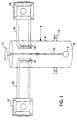
- bulb 2 is disposed in microwave cavity 4.
- Cavity 4 is cylindrical in shape (e.g. a cylindrical TE lll cavity), and has a solid portion 6, and a mesh portion 8 which passes the radiation emitted by bulb 2, but substantially contains the microwave power.
- Bulb 2 is attached to stem 10 which is rotated by motor 11 during lamp operation, while cooling air from jets (not shown) is applied to the bulb wall to cool the bulb.
- Cavity 4 contains slots 12 and 14, which are for coupling microwave power to the cavity.
- Retaining collar 15 secures the mesh portion of the cavity 8 and the solid portion 6.
- Bulb 2 is filled with a relatively high pressure fill, which is difficult to start.
- fills include various rare gas/halogen combinations for providing excimer radiation and/or electronegative species.
- a particular fill which may be used is 600-1500 torr of XeCl.
- Another fill which may be used is argon.
- Microwave generators 16 and 18 are provided, which may be magnetrons.
- the magnetrons generate microwave power which is fed through waveguides 20 and 22 respectively to coupling slots 12 and 14.
- the frequency of the microwave energy provided by magnetron 16 is lower than that which is provided by magnetron 18.
- Cavity 4 in the experimental stage may be provided with an adjustable end wall to find the resonant length.
- magnetron 18 is turned on and magnetron 16 is turned off. This may be accomplished by a timing circuit or by a photocell sensing the output of bulb 2, which is connected to switching electronics, the design of which is well known in the art.
- the frequency of magnetron 18 is selected to be higher than the frequency of magnetron 16 to compensate for the change in electrical dimensions after ignition, so that the cavity with the ignited bulb is resonant or near resonant at the frequency of the magnetron 18.
- the low frequency magnetron operated at 2440 Mhz, while the high frequency magnetron operated at 2470 Mhz.
- magnetron 16 provides a pulsed rather than continuous output, which may provide even more effective starting.
- the pulses would be of relatively high peak power and short duration.
- FIG. 2 A second embodiment of the invention is depicted in Figure 2.
- those parts which are also present in Figure 1 are identified with identical reference numerals.
- a cooling fluid is applied to the bulb immediately prior to turning the magnetron 16 on. This reduces the pressure of the components in bulb 2 and further facilitates the starting of the lamp.
- the cooling fluid is impinged onto the bulb under pressure, for example, by being sprayed.
- Timing circuitry well known to those skilled in the art, may be employed to make the spraying and magnetron turn-on operations automatic.
- liquid nitrogen storage tank 26 is shown. Cooling fluid under pressure is transported through line 28 to spray nozzle 30, where it is ejected in a spray onto bulb 2.
- spray nozzle 30 ejected in a spray onto bulb 2.
- a non-spray nozzle could be used, in which case, the fluid would be squirted onto the bulb.
- a particular application for the embodiment of Figure 2 is in the starting of lamps having excimer forming fills for providing excimer radiation.
- lamps having excimer forming fills for providing excimer radiation.
- halogen only or halogen/rare gas combinations may be used.
Landscapes
- Discharge Lamps And Accessories Thereof (AREA)
- Circuit Arrangements For Discharge Lamps (AREA)
Applications Claiming Priority (2)
| Application Number | Priority Date | Filing Date | Title |
|---|---|---|---|
| US08/568,290 US5767626A (en) | 1995-12-06 | 1995-12-06 | Electrodeless lamp starting/operation with sources at different frequencies |
| US568290 | 1995-12-06 |
Publications (2)
| Publication Number | Publication Date |
|---|---|
| EP0778722A2 true EP0778722A2 (fr) | 1997-06-11 |
| EP0778722A3 EP0778722A3 (fr) | 1998-03-04 |
Family
ID=24270695
Family Applications (1)
| Application Number | Title | Priority Date | Filing Date |
|---|---|---|---|
| EP96119616A Ceased EP0778722A3 (fr) | 1995-12-06 | 1996-12-06 | Mise en marche et opération d'une lampe sans électrodes avec sources des micro-ondes à des fréquences différentes |
Country Status (3)
| Country | Link |
|---|---|
| US (1) | US5767626A (fr) |
| EP (1) | EP0778722A3 (fr) |
| JP (1) | JPH09274994A (fr) |
Cited By (1)
| Publication number | Priority date | Publication date | Assignee | Title |
|---|---|---|---|---|
| US7993528B2 (en) * | 2007-04-25 | 2011-08-09 | Necamp David Richard | Method and apparatus for treating materials using electrodeless lamps |
Families Citing this family (6)
| Publication number | Priority date | Publication date | Assignee | Title |
|---|---|---|---|---|
| US5886479A (en) * | 1997-11-13 | 1999-03-23 | Northrop Grumman Corporation | Precession of the plasma torus in electrodeless lamps by non-mechanical means |
| US5923122A (en) * | 1998-04-08 | 1999-07-13 | Fusion Uv Systems, Inc. | Electrodeless bulb with means for receiving an external starting electrode |
| RU2156517C1 (ru) * | 1999-06-25 | 2000-09-20 | Корчагин Юрий Владимирович | Способ возбуждения и поддержания разряда в безэлектродной лампе и устройство для его осуществления |
| AU7489500A (en) * | 1999-09-20 | 2001-04-24 | Nordson Corporation | Apparatus and method for generating ultraviolet radiation |
| KR100480103B1 (ko) * | 2002-06-28 | 2005-04-06 | 엘지전자 주식회사 | 무전극 조명 시스템 |
| US20070103645A1 (en) * | 2005-11-01 | 2007-05-10 | Seiko Epson Corporation | Projector |
Family Cites Families (10)
| Publication number | Priority date | Publication date | Assignee | Title |
|---|---|---|---|---|
| US4749915A (en) * | 1982-05-24 | 1988-06-07 | Fusion Systems Corporation | Microwave powered electrodeless light source utilizing de-coupled modes |
| US4485332A (en) * | 1982-05-24 | 1984-11-27 | Fusion Systems Corporation | Method & apparatus for cooling electrodeless lamps |
| US4633140A (en) * | 1984-12-24 | 1986-12-30 | Fusion Systems Corporation | Electrodeless lamp having staggered turn-on of microwave sources |
| US4894592A (en) * | 1988-05-23 | 1990-01-16 | Fusion Systems Corporation | Electrodeless lamp energized by microwave energy |
| DE3920649A1 (de) * | 1988-06-24 | 1990-01-04 | Fusion Systems Corp | Verfahren und vorrichtung zur vergleichsmaessigung der temperaturverteilung von lampen fuer elektrodenlose leuchten |
| DE69206921T2 (de) * | 1991-08-14 | 1996-07-04 | Matsushita Electric Works Ltd | Elektrodenlose Entladungslampe |
| DE69315625T2 (de) * | 1992-06-30 | 1998-07-16 | Toshiba Lighting & Technology | Umrichterschaltung und Beleuchtungsgerät für eine elektrodenlose Entladungslampe mit solch einer Umrichterschaltung |
| CA2144978A1 (fr) * | 1992-09-30 | 1994-04-14 | Fusion Lighting, Inc. | Lampe sous electrode a ampoule rotative |
| US5519285A (en) * | 1992-12-15 | 1996-05-21 | Matsushita Electric Works, Ltd. | Electrodeless discharge lamp |
| US5448135A (en) * | 1993-10-28 | 1995-09-05 | Fusion Lighting, Inc. | Apparatus for coupling electromagnetic radiation from a waveguide to an electrodeless lamp |
-
1995
- 1995-12-06 US US08/568,290 patent/US5767626A/en not_active Expired - Fee Related
-
1996
- 1996-12-05 JP JP8325635A patent/JPH09274994A/ja active Pending
- 1996-12-06 EP EP96119616A patent/EP0778722A3/fr not_active Ceased
Non-Patent Citations (1)
| Title |
|---|
| None |
Cited By (1)
| Publication number | Priority date | Publication date | Assignee | Title |
|---|---|---|---|---|
| US7993528B2 (en) * | 2007-04-25 | 2011-08-09 | Necamp David Richard | Method and apparatus for treating materials using electrodeless lamps |
Also Published As
| Publication number | Publication date |
|---|---|
| EP0778722A3 (fr) | 1998-03-04 |
| US5767626A (en) | 1998-06-16 |
| JPH09274994A (ja) | 1997-10-21 |
Similar Documents
| Publication | Publication Date | Title |
|---|---|---|
| US6465964B1 (en) | Plasma treatment apparatus and plasma generation method using the apparatus | |
| US4266167A (en) | Compact fluorescent light source and method of excitation thereof | |
| US5838108A (en) | Method and apparatus for starting difficult to start electrodeless lamps using a field emission source | |
| US6054016A (en) | Magnetically enhanced microwave plasma generating apparatus | |
| US5747945A (en) | Electrodeless discharge lamp utilizing induced electric field generated by a high frequency electromagnetic field | |
| US4266166A (en) | Compact fluorescent light source having metallized electrodes | |
| HUT74897A (en) | Microwave source for electrodeless lamps | |
| US4185228A (en) | Electrodeless light source with self-contained excitation source | |
| JPH10223384A (ja) | 放電ランプ点灯装置 | |
| US5847517A (en) | Method and apparatus for igniting electrodeless lamp with ferroelectric emission | |
| US5767626A (en) | Electrodeless lamp starting/operation with sources at different frequencies | |
| US5923122A (en) | Electrodeless bulb with means for receiving an external starting electrode | |
| US3997816A (en) | Starting assist device for an electrodeless light source | |
| JP3150056B2 (ja) | プラズマ処理装置 | |
| US4766351A (en) | Starter for inductively coupled plasma tube | |
| US20010025607A1 (en) | Microwave plasma reactor and method | |
| JP2003505869A (ja) | 誘導性結合されたプラズマを用いて基板をエッチングする装置およびエッチングする方法 | |
| US3524144A (en) | Laser generator having a shock-induced narrow band illuminator | |
| US6130512A (en) | Rf capacitively-coupled electrodeless light source | |
| JPH11283775A (ja) | 無電極放電灯装置及び照明装置 | |
| US20090153071A1 (en) | Ignition circuit for igniting a discharge lamp and method for igniting the discharge Lamp | |
| JP2007213821A (ja) | マイクロプラズマジェット制御方法及び装置 | |
| JPH0665178B2 (ja) | 環状の無電極放電光源装置およびその点灯方法 | |
| KR800001141B1 (ko) | 무전극 방전 램프 | |
| JP2603294Y2 (ja) | 無電極放電灯点灯装置 |
Legal Events
| Date | Code | Title | Description |
|---|---|---|---|
| PUAI | Public reference made under article 153(3) epc to a published international application that has entered the european phase |
Free format text: ORIGINAL CODE: 0009012 |
|
| AK | Designated contracting states |
Kind code of ref document: A2 Designated state(s): DE FR GB |
|
| PUAL | Search report despatched |
Free format text: ORIGINAL CODE: 0009013 |
|
| AK | Designated contracting states |
Kind code of ref document: A3 Designated state(s): DE FR GB |
|
| 17P | Request for examination filed |
Effective date: 19980817 |
|
| 17Q | First examination report despatched |
Effective date: 19991229 |
|
| GRAG | Despatch of communication of intention to grant |
Free format text: ORIGINAL CODE: EPIDOS AGRA |
|
| STAA | Information on the status of an ep patent application or granted ep patent |
Free format text: STATUS: THE APPLICATION HAS BEEN REFUSED |
|
| 18R | Application refused |
Effective date: 20010806 |