EP0778638A2 - Modularer RJ-Verbinder - Google Patents
Modularer RJ-Verbinder Download PDFInfo
- Publication number
- EP0778638A2 EP0778638A2 EP96108461A EP96108461A EP0778638A2 EP 0778638 A2 EP0778638 A2 EP 0778638A2 EP 96108461 A EP96108461 A EP 96108461A EP 96108461 A EP96108461 A EP 96108461A EP 0778638 A2 EP0778638 A2 EP 0778638A2
- Authority
- EP
- European Patent Office
- Prior art keywords
- modular
- jack
- groove
- plate member
- card
- Prior art date
- Legal status (The legal status is an assumption and is not a legal conclusion. Google has not performed a legal analysis and makes no representation as to the accuracy of the status listed.)
- Withdrawn
Links
Images






Classifications
-
- H—ELECTRICITY
- H01—ELECTRIC ELEMENTS
- H01R—ELECTRICALLY-CONDUCTIVE CONNECTIONS; STRUCTURAL ASSOCIATIONS OF A PLURALITY OF MUTUALLY-INSULATED ELECTRICAL CONNECTING ELEMENTS; COUPLING DEVICES; CURRENT COLLECTORS
- H01R13/00—Details of coupling devices of the kinds covered by groups H01R12/70 or H01R24/00 - H01R33/00
- H01R13/40—Securing contact members in or to a base or case; Insulating of contact members
-
- H—ELECTRICITY
- H01—ELECTRIC ELEMENTS
- H01R—ELECTRICALLY-CONDUCTIVE CONNECTIONS; STRUCTURAL ASSOCIATIONS OF A PLURALITY OF MUTUALLY-INSULATED ELECTRICAL CONNECTING ELEMENTS; COUPLING DEVICES; CURRENT COLLECTORS
- H01R24/00—Two-part coupling devices, or either of their cooperating parts, characterised by their overall structure
- H01R24/60—Contacts spaced along planar side wall transverse to longitudinal axis of engagement
- H01R24/62—Sliding engagements with one side only, e.g. modular jack coupling devices
-
- H—ELECTRICITY
- H01—ELECTRIC ELEMENTS
- H01R—ELECTRICALLY-CONDUCTIVE CONNECTIONS; STRUCTURAL ASSOCIATIONS OF A PLURALITY OF MUTUALLY-INSULATED ELECTRICAL CONNECTING ELEMENTS; COUPLING DEVICES; CURRENT COLLECTORS
- H01R13/00—Details of coupling devices of the kinds covered by groups H01R12/70 or H01R24/00 - H01R33/00
- H01R13/62—Means for facilitating engagement or disengagement of coupling parts or for holding them in engagement
-
- H—ELECTRICITY
- H01—ELECTRIC ELEMENTS
- H01R—ELECTRICALLY-CONDUCTIVE CONNECTIONS; STRUCTURAL ASSOCIATIONS OF A PLURALITY OF MUTUALLY-INSULATED ELECTRICAL CONNECTING ELEMENTS; COUPLING DEVICES; CURRENT COLLECTORS
- H01R12/00—Structural associations of a plurality of mutually-insulated electrical connecting elements, specially adapted for printed circuits, e.g. printed circuit boards [PCB], flat or ribbon cables, or like generally planar structures, e.g. terminal strips, terminal blocks; Coupling devices specially adapted for printed circuits, flat or ribbon cables, or like generally planar structures; Terminals specially adapted for contact with, or insertion into, printed circuits, flat or ribbon cables, or like generally planar structures
- H01R12/70—Coupling devices
- H01R12/71—Coupling devices for rigid printing circuits or like structures
- H01R12/72—Coupling devices for rigid printing circuits or like structures coupling with the edge of the rigid printed circuits or like structures
- H01R12/722—Coupling devices for rigid printing circuits or like structures coupling with the edge of the rigid printed circuits or like structures coupling devices mounted on the edge of the printed circuits
-
- H—ELECTRICITY
- H01—ELECTRIC ELEMENTS
- H01R—ELECTRICALLY-CONDUCTIVE CONNECTIONS; STRUCTURAL ASSOCIATIONS OF A PLURALITY OF MUTUALLY-INSULATED ELECTRICAL CONNECTING ELEMENTS; COUPLING DEVICES; CURRENT COLLECTORS
- H01R13/00—Details of coupling devices of the kinds covered by groups H01R12/70 or H01R24/00 - H01R33/00
- H01R13/62—Means for facilitating engagement or disengagement of coupling parts or for holding them in engagement
- H01R13/627—Snap or like fastening
- H01R13/6271—Latching means integral with the housing
- H01R13/6272—Latching means integral with the housing comprising a single latching arm
Definitions
- the present invention relates to a modular-jack connector to be provided at an end portion of a relatively thin plate member and makes it possible to connect a modular-jack to the plate member directly.
- cards are used, for example, in computer devices such as personal computers and work stations etc., or in electronic equipments such as multi-functional telephone sets, and they are used by being inserted into card slots provided on the bodies of the equipments.
- the card with so-called modem function needs a modular-jack connector (i.e. a connector for a modular-jack) to be connected with a modular-jack, in order to interface with an outer telecommunication line such as a telephone line for instance, in addition to a connector for connecting the card to the body of the equipment.
- a modular-jack connector i.e. a connector for a modular-jack
- the term of "thin” indicates that the thickness is equal or less than the height or width dimension of the modular-jack to be connected
- the term of "thin device” indicates thin plate member provided with electric circuits or electronic circuits, including said electronic cards named PC card or IC card.
- connectors 111,121 for a dedicated conversion cable 112 or an adapter 122 are provided at the rear sides of thin devices ( e.g. PC cards ) 110,120, and modular-jacks are connected to them through the conversion cable 112 or the adapter 122.
- a modular-jack 113 is connected to an end portion of the conversion cable 112, and in the example shown in Fig.28, a modular-jack connector 123 is provided on the back side of the adapter 122.
- Japanese patent Laid-open Publication No. Hei 6-52923, Hei 6-61658, Hei 6-176813 or Japanese utility model Laid-open publication No. Hei 6-19289 etc. disclose a constitution of a card being provided with an insert-opening vertical to the plane area thereof, wherein a modular-jack being to be inserted into said opening in the vertical direction to the card plane.
- said Japanese utility model Laid-open Hei 6-19289 also discloses a construction of a card being provided with an inserting groove turned sideways by 90 degrees and elongated in the direction along the card plane at a rear end face of the card, and a modular-jack is to be inserted into said groove, being turned sideways by 90 degrees.
- a guide means which guides the inserting motion of the modular-jack, a stopper means which stops the modular-jack to a set position and a securing means which secures the inserted modular-jack in inserted state are formed as one body-like in the card walls.
- the above-mentioned conventional modular-jack connectors in the case of the connector having the insert-opening vertical to the plane area of the card, since the inserting direction of the modular-jack is vertical to the plane area of the card, the connector is commonly inconvenient to use, and has a problem that application of the card is limited, in particular, when it is used in an equipment with a plurality of card slots close to each other, these card slots can not be used at a time.
- the thickness of the portion forming the connector thereon must be designed greater a certain degree than the width dimension of the modular-jack, and this limits to reduce the thickness of that portion.
- the present invention has been developed to solve the above-mentioned conventional problems, and has objects of providing a modular-jack connector which allows a modular-jack to connect with a plate member directly without any other connecting appliances such as dedicated conversion cables or adapters etc., and being convenient to use, in connecting a modular-jack to a relatively thin plate member.
- a modular-jack connector which is to be provided at an end portion of a plate member having a predetermined thickness, allowing a modular-jack to connect with the plate member directly by inserting the modular-jack in a direction along a plane of the plate member, comprising: a groove for inserting the modular-jack thereinto, being provided at an end portion of the plate member, being elongated from an end face of the end portion to inner side of the plate member, and opens on one side in a thickness direction of the plate member; a connector electrode being provided on an inside wall of the groove, and being able to contact with an electrode of the modular-jack when the modular-jack is inserted into the groove; a securing member being formed as a separated part from the plate member, being placed on said one side in the thickness direction of the plate member, and secures said modular-jack inserted into the groove in an inserted state; and a support means which supports the securing
- the thickness of said plate member does not need to be designed greater than the height dimension of the modular-jack, because the groove for insertion of the modular-jack opens on one side in the thickness direction of the plate member and the securing member which secures the modular-jack inserted into the groove in inserted state is formed as a separated part from the plate member.
- the above-mentioned connector makes it possible to connect the modular-jack directly to the plate member the thickness of which is equal or less than the height dimension of the modular-jack, without any other connecting appliances such as dedicated conversion cables and adapters.
- the modular-jack connector in accordance with the invention is convenient to use, in comparison with conventional one wherein a modular-jack being inserted into the opening vertically to the plane area of the card, because the modular-jack can be inserted into the groove of the modular-jack connector in the direction along the plane of the plate member, further, since no bending moment act on the plate member when the modular-jack is inserted, the possibility of acting a bad influence upon durability of the plate member will be eliminated.
- a biassing mechanism which biases the modular-jack in a reverse direction of its insertion is further provided in the groove.
- a shutter slidable in an insert direction of the modular-jack may be provided in the groove, the shutter covering the connector electrode when the modular-jack is not inserted, and being slidden in the groove inwardly further than a position of the connector electrode when the modular-jack is inserted.
- the shutter slidable in the inserting direction of the modular-jack is provided in the groove and the connector electrode of the modular-jack connector is covered by said shutter when the modular-jack is not inserted, the connector electrode can be protected effectively when the connector is not in use.
- a biassing means which biases the modular-jack in a reverse direction of its insertion is further provided to the shutter.
- the securing means is changeable between an accommodated position laid down on a bottom wall of the groove and a securing position raised from the bottom wall of the groove to secure the modular-jack.
- the securing member can be formed relatively thick, because it is accommodated in lying down on the bottom wall of the groove. That is to say, the thickness of the securing member can be determined to be equal to the depth dimension of the groove at maximum, for example, in the scope of the thickness of the plate member is kept not to increase. Accordingly, it comes to be possible to increase the strength and rigidity of the securing member.
- the securing member is accommodated in the groove not to exceed a surface of the plate member in the accommodated position.
- the increase of the total thickness of the plate member including the thickness of the securing member can be firmly prevented, because the securing member is accommodated in the groove not to exceed the surface of the plate member.
- a pair of transverse slots perpendicular to the groove may be provided on both side walls of the groove, and the securing member is formed by being divided into two parts in perpendicular to the insert direction of the modular-jack, each half of the securing member being positioned to an opening of the transverse slot to the groove, and being changeable between an accommodated position laid down on a bottom wall of each transverse slot and a securing position raised from the bottom wall of each transverse slot to secures the modular-jack .
- the thickness of the securing member depends upon only the width dimension of said transverse slot, and can be determined in no relation to the thickness of the plate member. Therefore, the thickness of the securing member can be designed to be thicker all the more, and it comes to be possible to increase its strength and rigidity.
- each half of the securing member is accommodated in the transverse slot not to exceed the surface of the plate member in the accommodated position.
- the increase of the total thickness of the plate member including the thickness of the securing member can be surely prevented, because each half of the securing member can be accommodated in each transverse slot not to exceed the surface of the plate member.
- a plurality of modular-jack connectors may be provided at an end portion of the plate member, and at least one of them is provided, with regard to an obverse and reverse of the plate member, on a reverse side to other connectors.
- the modular-jack when there exist some interruptions on whichever side of the obverse and reverse of the plate member, by using the connector provided on the other side, the modular-jack can be connected to the plate member without any trouble. Accordingly, the convenience of the connector can be elevated higher.
- the plate member may form a body of a thin device.
- the plate member may be formed as a separated part from a body of a thin device, and contained in a containing cavity provided at an end portion of the body.
- the connector electrode of the modular-jack connector can be protected effectively, because the modular-jack connector is provided on the plate member formed as a separated part from the body of the thin device and the plate member is contained in the cavity provided at the end portion of the body of the thin device when the modular-jack is not connected thereto. Also, when the modular-jack is not connected, an appearance of the end portion of the thin device is improved.
- a slide member being slidable to the inside wall may be positioned, and the plate member may be retained rotatably to the slide member.
- the plate member is retained rotatably to the slide member, the plate member is provided with a degree of freedom in the rotating direction and a still higher convenience is obtained in connecting modular-jack thereto.
- Fig.1, Fig.2 and Fig.3 show the perspective view, the side view and the disassembled perspective view of a PC card in the first embodiment of the modular-jack connector according to the present invention.
- the PC card 1 is formed generally as a plate-like member having a predetermined thickness less than the height dimension of a modular-jack to be connected thereto, and a main-connector 4 for connection with an equipment (not shown) in which the PC card is to be used, is mounted on an end (front end) portion.
- the periphery of the card body 1, except for that front end, is surrounded by a frame 2 made of plastic.
- Said PC card 1 is provided with an electric circuit board 3 on which prescribed electronic components are mounted, the main-connector 4 mounted at an end of the electric circuit board 3 and to be connected to electric circuits of the board 3, and a pair of panels made of e.g. metal which cover upper and lower of the electric circuit board 3 respectively.
- the PC card 1 is assembled as one body, by stacking the frame 2 and the electric circuit board 3 in prescribed order and by binding them each other, after mounting the main-connector 4 to the electric circuit board 3.
- a modular-jack connector 10 for connecting a modular-jack to the PC card 1 directly.
- This modular-jack connector 10 is formed in a groove 11 which elongates from the rear end face 1r to inner side of the card in a direction along the card plane, and opens on one side in a thickness direction of the card 1.
- This groove 11 has suitable width to receive the modular-jack and insert it thereinto smoothly, and each wall (inner wall 11a, bottom wall 11b and left and right side wall 11c,11d) is formed as a part of plastic frame 2, as is understood well from Fig.3.
- said modular-jack connector 10 is provided with a pair of leaf spring-like connector electrodes 12 which may contact with an electrode of the modular-jack 9 when this is inserted, and a securing member 15 which may secure the modular-jack 9 inserted into the groove 11 in a inserted state.
- Said modular-jack 9 is the same as one well known conventionally, therefore, detailed explanations, for example, about its inner construction etc. are eliminated.
- Said connector electrodes 12 are placed on one of the walls (the bottom wall 11b, in this embodiment) define the groove 11, and are connected to an electric circuit on the electric circuit board 3 through electro-conductivities 13.
- a connector electrode 12 and a electro-conductivity 13 are formed in one body, and the electro-conductivity 13 is connected to an electric circuit by soldering for instance at an end portion thereof, and its major part is buried to fix itself in the bottom wall 11b of the groove 11.
- Said securing member 15 is formed by bending work of a metal wire rod for instance, and, as shown in detail in Fig.9 and Fig.10, it is provided with a pair of engaging stairs 15a which engage with the lever 9a of the inserted modular-jack 9, and a pair of shafts 15b to be supported rotatably against the PC card 1.
- a pair of stairs 11e having a depth dimension greater than a thickness of the securing member 15 at least, and on the side at a prescribed portion of relatively inner side of each stair 11e, there provided a pair of holes 11h which support the shafts 15b of the securing member 15 rotatably.
- the securing member 15 is mounted to the PC card 1 by inserting each shaft 15b into the hole 11h, and each shaft 15b of the securing member 15 and each hole 11h formed at each stair 11e of the groove 11 form the support means which supports the securing member 15 changeably between an accommodated position in a direction along a plane of the PC card 1 and a securing position raised from the direction along the plane of the PC card 1 to secure the modular-jack 9.
- the securing member 15 is, as is understood well from Fig.4 and Fig.6, accommodated in the groove 11 (i.e. in the stairs 11e), being held in horizontal along the plane direction of the PC card 1, and not to exceed the surface of the PC card 1, when any modular-jack is not inserted into the groove. Accordingly, in this accommodated state of the securing member 15, the total thickness of the PC card 1 including the thickness of the securing member 15 is kept within the body thickness of the PC card 1.
- the securing member in inserting the modular-jack 9 into the groove 11, the securing member is to be raised by pivoting at first, and the modular-jack 9 is inserted into the groove 11 in the direction along the plane of the PC card 1.
- the inserting motion of the modular-jack 9 is guided by left and right wall 11c,11d and the bottom wall 11b of the groove 11, and stopped by the inner wall 11a at a prescribed set position.
- the modular-jack 9 is secured in inserted position, because its lever 9a is engaged with the stairs 15a of the securing member 15, and prevented it from coming off surely.
- the modular-jack 9 is connected to the PC card 1 directly, by inserting it into said groove 11 in the direction along the plane of the PC card 1.
- the engagement of the securing member 15 with the lever 9a of the modular-jack 9 is to be released by pushing down the lever 9a and lifting up the securing member 15, and then the modular-jack 9 is drawn from the groove 11.
- the thickness of PC card 1 does not need to be determined greater than the height dimension of the modular-jack, because the groove 11 for insertion of said modular-jack opens on one side in the thickness direction of the PC card 1 and the securing member 15 which secures the modular-jack 9 inserted into the groove in an inserted state is produced as a separated part from the body of the PC card 1. Also, in this case, the total thickness of the PC card 1 including the thickness of the securing member 15 does not increase, because the securing member 15 is accommodated in the groove 11 not to exceed the surface of the PC card in its accommodated position.
- the above-mentioned connector makes it possible to connect the modular-jack 9 directly to the PC card 1 whose thickness is equal or less than the height dimension of the modular-jack 9, without any other connecting appliances such as dedicated conversion cables and adapters.
- the modular-jack connector in accordance with the invention is convenient to use, in comparison with conventional one wherein a modular-jack being inserted into the opening vertically to the plane area of the card, because the modular-jack 9 can be inserted into the groove 11 of the modular-jack connector 10 in the direction along the plane of the PC card 1. Further, since no bending moment act on the PC card 1 when the modular-jack is inserted, the possibility that the connecting operation of the modular-jack 9 acts a bad influence upon durability of the PC card 1 is eliminated.
- a biassing mechanism which biases the modular-jack 9 in reverse direction to its insertion is provided, in the groove 21 being formed at the rear end portion of a PC card 23.
- a movable plate 26 parallel to the inner wall 21a is placed in the groove 21, and an elastic body 27 consists of e.g. a coil spring is arranged between the movable plate 26 and the inner wall 21a.
- the biassing mechanism which biases the modular-jack 9 in reverse direction to its insertion is consists of said coil spring 27 and said movable plate 26.
- the length of said coil spring 27 is kept to its free length (refer to Fig.13), when the modular-jack 9 is not connected to the modular-jack connector 20 (i.e. not inserted into the groove 21).
- a coil spring 27 is used as the elastic body arranged between the inner wall 21a of the groove and the movable plate 26, however, another kind of spring such as leaf spring or some substance which has high elasticity such as rubber may be arranged alternatively.
- the movable plate 26 is moved to the inner side of the groove 21 against the biassing force of the coil spring 27. And, after the travelling length reaches equal or more a predetermined value, the modular-jack 9 can be secured in an inserted condition, by engaging the engaging stair 15a of the securing member 15 with the lever 9a of the modular-jack 9.
- the coil spring 27 is in a compressed state by a certain length from its free length, the modular-jack 9 is pushed by the biassing force corresponding to the compression in reverse direction to its inserting motion, and the modular-jack 9 is to be secured firmly, being sandwiched between the movable plate 26 and the securing member 15 (refer to Fig.14).
- L-shape protrusion 26a is formed, and, on left and right wall 21c,21d of the groove 21, a guide groove 21g which fits each protrusion 26a thereinto is formed in direction of insertion of modular-jack 9, and the movable plate 26 may move smoothly, since each of left and right protrusion 26a moves in each guide groove 21g respectively.
- the advantages same as in the first embodiment is obtained, also, since the coil spring 27 and the movable plate 26 are provided as a biassing mechanism which biases the modular-jack 9 in reverse direction to its insertion are further provided, the modular-jack 9 inserted into the groove 21 is secured more firmly in the groove 21 to prevent its coming off surely, and the reliability of the connection between the modular-jack 9 and the connector 20 is raised still higher.
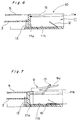
- a shutter 36 slidable in the insert direction of the modular-jack 9 is placed in the groove 31.
- Said shutter 36 consists of a vertical wall 36a of which the height is generally equal to the depth dimension of the groove 31, and a ceiling 36b elongated from the upper end of the vertical wall 36a perpendicularly thereto and has a prescribed length.
- the shutter has a suitable width dimension for being accommodated in the groove 31 and for sliding smoothly therein.
- the groove 31 is formed so that the length in its inner direction is longer than by a predetermined value than that of the shutter 36, and this shutter 36 can slide by said predetermined length at maximum.
- the shutter 36 When the modular-jack 9 is not inserted, the shutter 36 is placed to the initial position where the vertical wall 36 is aligned in generally flat with the rear end face 33r of the PC card 33, in this condition, the connector electrodes 12 of the modular-jack connector 30 are covered by the shutter 36 (refer to Fig.15 and Fig.16).
- the shutter 36 is pushed by the modular-jack 9 and slidden to the inner side of the groove 31 further than the position of the electrodes 12, and, this enable the contact between the electrodes 12 and the electrode (not shown) of the modular-jack 9 (refer to Fig.17).
- an elastic body consists of e.g. a coil spring 37 is arranged as a biassing mechanism which biases the modular-jack 9 in the reverse direction to its insertion.
- the length of said coil spring 37 is determined to be kept in its free length when the shutter 36 is positioned to the initial position (refer to Fig.16).
- the shutter 36 is moved to the inner side of the groove 31 against the biassing force of the coil spring 37. And after the travelling length reaches equal or more a predetermined value, the modular-jack 9 can be secured in an inserted condition, by engaging the securing member 35 with the lever 9a of the modular-jack 9.
- the coil spring 37 is in a compressed state by a certain length from its free length, the modular-jack 9 is pushed by the biassing force corresponding to the compression in the reverse direction to its insertion, and said modular-jack 9 is to be secured firmly, being sandwiched between the shutter 36 and the securing member 35.
- a coil spring 37 is used as the elastic body arranged between the inner wall 31a of the groove and the vertical wall 36a of the shutter 36, but, another kind of spring such as leaf spring or some substance which has high elasticity such as rubber may be used alternatively.
- a pair of bosses 33b a little raised from the card surface are provided, and left and right shafts 35b are supported rotatably by said bosses 33b. Therefore, the shutter 36 can slide without any interruption with the securing member 35, even if the securing member 35 is in the accommodated condition.
- the securing member may be accommodated in the stair provided on the upper side of the groove alternatively, as same as in the first or second embodiment.
- the height of shutter may be reduced by the depth of the stair for accommodating the securing member. This makes it possible to reduce the thickness of the card by the height dimension of the bosses 33b.
- the advantages same as in the first embodiment is obtained, except for the securing member 35 is placed on the surface of the PC card 33 in the accommodated condition. Also, in this case, since the shutter 36 slidable in the inserting direction of the modular-jack is provided in the groove 31, and the connector electrodes 12 of the modular-jack connector 30 are covered by said shutter 36 when the modular-jack is not inserted, the connector electrodes 12 can be protected effectively when the connector 30 is not in use.
- said biassing mechanism which biases the modular-jack 9 in the reverse direction to its insertion is further provided to the shutter 36, the modular-jack 9 inserted into the groove 31 is secured more firmly in the groove 31 to prevent it from coming off surely, the reliability of the connection between the modular-jack 9 and the connector 30 is elevated still higher.
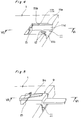
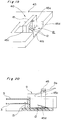
- a securing member 45 which secures the modular-jack 9 is accommodated in the groove 41, being lied down on the bottom wall 41b of the groove 41 (refer to Fig.18), and when the modular-jack 9 is connected, the position of the securing member is changed to the securing position that secure the modular-jack 9, being raised from the bottom wall 41b of the groove (refer to Fig.19 and Fig.20).
- Said securing member 45 can be formed thicker than that of the connectors in the 1st - the 3rd embodiment, because it is accommodated lying down on the bottom wall 41b of the groove. In other words, in the scope of the thickness of the PC card is kept not to increase, the thickness of the securing member 45 can be designed to be equal to the depth dimension of the groove 41 at maximum.
- the securing member 45 is formed basically to be for example rectangular in its cross section.
- the end portions of left and right side column 45c are supported rotatably on left and right wall 41c,41d of the groove 41 respectively, and can be rotated by about 90 degrees between an accommodated position and a securing position.
- a curved surface portion 45d is provided at the end portion of said column 45c, so that rotating motion of the securing member 45 can be performed smoothly.
- said securing member 45 can be formed relatively thick (the thickness equal to the depth dimension of the groove 41 at maximum, in the scope of the thickness of the PC card 43 is kept not to increase), the strength and rigidity of the securing member can be increased remarkably.
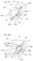
- a pair of transverse slots 52 having generally same depth as the groove 51 and are perpendicular thereto are formed.
- the securing member 55 is formed, being divided into two pieces in the direction perpendicular to insert direction of modular-jack, and each half piece 55H of the securing member 55 is positioned at the opening 52p of each transverse slot 52 to the inserting groove 51 for a modular-jack. They are accommodated in lying down on the bottom wall of each transverse slot 52 respectively, when the modular-jack is not connected (refer to Fig.21).
- each half 55H of the securing member 55 is accommodated in each transverse slot 52 not to exceed the surface of PC card 53, therefore, the total thickness of PC card 53 including said securing member 55 is kept within the thickness of the body of PC card 53, in the accommodating condition of the securing member 55.
- the thickness of the securing member 55 depends upon only the width of the transverse slot 52, and can be determined in no relation to the thickness of PC card 53.
- Each half piece 55H of the securing member 55 is formed basically to be e.g. rectangular in its cross section, and the end portions of the column 55c are supported rotatably on the walls of the transverse slot 52.
- the position of the each half is changed to the securing position that secure the modular-jack 9, being raised from the bottom wall of the transverse slot 52 (refer to Fig.22).
- the bottom plate 55e for fixing is formed at the end portion of the column 55c of each half 55H, on the other hand, a rectangular concavity 51e a little larger than said bottom plate 55e is provided on the bottom wall 51b of the groove 51, and more preferably, the depth of said concavity 51e is determined to be equal or more than the thickness of the bottom plate 55e.
- the bottom plate 55e is fixed under the modular-jack 9, being fitted in the concavity 51e, and each half 55H is fixed to the bottom wall 51b of the groove 51.
- the same effects as the first embodiment is obtained, and particularly, since each half 55H is accommodated in each transverse slot 52 perpendicular to the inserting groove 51 for the modular-jack 9, the thickness of said securing member 55 depends upon only the width of the transverse slot 52, and can be determined in no relation to the thickness of PC card 53. Therefore, it becomes to be possible to design the thickness of the securing member 55 to be greater than that of the connector in the fourth embodiment.
- a plurality of modular-jack connectors with same function are provided at a rear end portion of a PC card, and at least one connector is provided on reverse side to the others, with regard to the obverse and reverse of the PC card.
- a couple of modular-jack connectors 60 are provided on reverse side each other, with regard to the obverse and reverse of the PC card.
- the same connectors 60 for a modular-jack as shown in the first embodiment are provided at the end portion of the PC card 63, however, the connectors are not to be limited to that type, and, another type of modular-jack connectors may be provided. Also, different types of modular-jack connectors may be provided on the obverse and reverse side of the PC card.
- a cavity 74 is formed at an end portion of a PC card 73, and in said cavity 74, a connector unit 79 being fabricated separately from the card body 73 is contained drawably to rear side.
- Said connector unit 79 is constructed, by forming a inserting groove 71 for a modular-jack in the plate-like base plate 78, and mounting the securing member 75 for securing modular-jack to said groove 71. Then, the connector unit 79 become to be available to use, by drawing the base plate 78 from the cavity 74.
- securing member the same one as described in the fourth embodiment is shown in the Fig.24, however, another type of securing member may be provided alternatively.
- a pair of rod-like slide guides 77 guided through the guide grooves 74g formed on the cavity side walls are provided, and stopper 77a for preventing from dropping off is formed at an end portion of each slide guide 77.
- the connector unit 79 is designed so that its end face protrudes a little from the rear end face 73r of PC card 73, in the contained condition in the cavity 74.
- the connector electrode (not shown) of the modular-jack connector 70 can be protected effectively, because the modular-jack connector 70 is provided on the connector unit 79 being formed as a separated component from the card body 73 and the connector unit 79 is contained in the cavity 74 provided at the end portion of the card body 73 when the modular-jack is not connected thereto. Also, when the modular-jack is not connected, the appearance of said end portion of the PC card 73 is improved.
- a pair of holders 86 for holding the connector unit 89 are provided at the end portion of each slide guide 87 which can slide along the guide groove 84g on each side wall of the cavity 84, and the base plate 88 of the connector unit 89 is supported rotatablly by the pin 86p mounted to the holder 86.
- the base plate 88 can be rotate continuously within 180 degrees at maximum around said pin 86p, and the angle of the connector unit 89 to the PC card 83 can be changed properly in accordance with the circumferential condition.
- a desired one may be provided in the groove 81 formed on the connector unit 89.
- drawer type of connector unit 79,89 shown in the seventh or the eighth embodiment to the rear end portion of the PC card, as shown in the sixth embodiment, and at least one may be provided on the reverse side to the others, with regard to the obverse and reverse side of the PC card.
- a modular-jack connector allowing a modular-jack to connect with a plate member directly and being convenient to use is provided.
- a groove 11 for inserting the modular-jack thereinto is provided at an end portion of a PC card 1, the groove is elongated from an end face of the end portion to inner side of the PC card 1 in a direction along the card plane, and opens on one side in a thickness direction of the PC card 1.
- connector electrodes 12 being able to contact with an electrode of the modular-jack is provided on an inside wall 11b of the groove 11.
- the modular-jack connector has a securing member 15 for securing the modular-jack, being formed as a separated part from the PC card 1, and a support means 11h,15b which supports the securing member changeably between an accommodated position in the direction along the plane of the PC card 1 and a securing position to secure the modular-jack.
Landscapes
- Connector Housings Or Holding Contact Members (AREA)
- Details Of Connecting Devices For Male And Female Coupling (AREA)
- Coupling Device And Connection With Printed Circuit (AREA)
Applications Claiming Priority (2)
| Application Number | Priority Date | Filing Date | Title |
|---|---|---|---|
| JP316433/95 | 1995-12-05 | ||
| JP7316433A JPH09161874A (ja) | 1995-12-05 | 1995-12-05 | モジュラージャック用コネクタ |
Publications (2)
| Publication Number | Publication Date |
|---|---|
| EP0778638A2 true EP0778638A2 (de) | 1997-06-11 |
| EP0778638A3 EP0778638A3 (de) | 1998-03-18 |
Family
ID=18077036
Family Applications (1)
| Application Number | Title | Priority Date | Filing Date |
|---|---|---|---|
| EP96108461A Withdrawn EP0778638A3 (de) | 1995-12-05 | 1996-05-28 | Modularer RJ-Verbinder |
Country Status (4)
| Country | Link |
|---|---|
| EP (1) | EP0778638A3 (de) |
| JP (1) | JPH09161874A (de) |
| KR (1) | KR970054920A (de) |
| TW (1) | TW287323B (de) |
Cited By (4)
| Publication number | Priority date | Publication date | Assignee | Title |
|---|---|---|---|---|
| EP1109268A1 (de) * | 1999-12-15 | 2001-06-20 | Avaya Technology Corp. | Modular Stecker mit Steckerpositionierungselement |
| FR2839393A1 (fr) * | 2002-05-02 | 2003-11-07 | Mitsubishi Electric Corp | Agencement d'un element femelle et dispositif mobile. |
| CN103179477A (zh) * | 2011-12-21 | 2013-06-26 | 欧力天工股份有限公司 | 传声器电缆的连接构造及具备该连接构造的传声器装置 |
| CN114759397A (zh) * | 2021-07-30 | 2022-07-15 | 智能移动机器人(中山)研究院 | 一种模块化供电装置及其供电方法 |
Families Citing this family (2)
| Publication number | Priority date | Publication date | Assignee | Title |
|---|---|---|---|---|
| JP2013157411A (ja) * | 2012-01-30 | 2013-08-15 | Chugoku Electric Power Co Inc:The | ケーブル接続装置 |
| JP5969337B2 (ja) * | 2012-09-14 | 2016-08-17 | 日本圧着端子製造株式会社 | モジュラージャック |
Family Cites Families (2)
| Publication number | Priority date | Publication date | Assignee | Title |
|---|---|---|---|---|
| GB2294820B (en) * | 1992-04-08 | 1996-07-24 | Megahertz Corp | Media connector interface for use with a PCMCIA-architecture communications card and method |
| JP2910500B2 (ja) * | 1993-04-19 | 1999-06-23 | 住友電装株式会社 | 電気自動車充電用コネクタ |
-
1995
- 1995-12-05 JP JP7316433A patent/JPH09161874A/ja active Pending
-
1996
- 1996-03-02 TW TW085102652A patent/TW287323B/zh active
- 1996-05-28 EP EP96108461A patent/EP0778638A3/de not_active Withdrawn
- 1996-07-04 KR KR1019960027130A patent/KR970054920A/ko not_active Ceased
Cited By (6)
| Publication number | Priority date | Publication date | Assignee | Title |
|---|---|---|---|---|
| EP1109268A1 (de) * | 1999-12-15 | 2001-06-20 | Avaya Technology Corp. | Modular Stecker mit Steckerpositionierungselement |
| AU778544B2 (en) * | 1999-12-15 | 2004-12-09 | Avaya Technology Corp. | Modular jack having a plug-positioning member |
| FR2839393A1 (fr) * | 2002-05-02 | 2003-11-07 | Mitsubishi Electric Corp | Agencement d'un element femelle et dispositif mobile. |
| CN103179477A (zh) * | 2011-12-21 | 2013-06-26 | 欧力天工股份有限公司 | 传声器电缆的连接构造及具备该连接构造的传声器装置 |
| CN103179477B (zh) * | 2011-12-21 | 2018-01-26 | 欧力天工股份有限公司 | 传声器电缆的连接构造及具备该连接构造的传声器装置 |
| CN114759397A (zh) * | 2021-07-30 | 2022-07-15 | 智能移动机器人(中山)研究院 | 一种模块化供电装置及其供电方法 |
Also Published As
| Publication number | Publication date |
|---|---|
| EP0778638A3 (de) | 1998-03-18 |
| KR970054920A (ko) | 1997-07-31 |
| JPH09161874A (ja) | 1997-06-20 |
| TW287323B (en) | 1996-10-01 |
Similar Documents
| Publication | Publication Date | Title |
|---|---|---|
| CN109638562B (zh) | 具有配合引导特征的电连接器系统 | |
| US6241534B1 (en) | GBIC connector with circuit board mating faces | |
| CN1162999C (zh) | 光电收发模组 | |
| US20020197043A1 (en) | Stacked GBIC guide rail assembly | |
| EP1429422B1 (de) | Steckverbinder, der die Dicke eines zu montierenden Gerätes verringert | |
| US6139338A (en) | CF card adapter | |
| JP2002508579A (ja) | 薄型形状モジュラ電気ジャックおよびそのジャックを備える通信カード | |
| EP0319901B1 (de) | Gerät zum Einstellen einer Schaltungsplatte | |
| EP0974176B1 (de) | Beweglich geführter elektrischer steckverbinder und methode | |
| US6488543B2 (en) | Modular jack for type III PCMCIA cards | |
| US5637001A (en) | PCMCIA connection device | |
| US20020132523A1 (en) | Connector scheme for use with handheld computers and accessory devices | |
| US20020081878A1 (en) | Twistable connector and provider assembly | |
| JP2000277200A (ja) | ソケット装置 | |
| EP1729487A1 (de) | Verbinderanordnung zur Verbindung von einem Mobiltelefon mit einem Peripheriegerät | |
| CN1125728C (zh) | 打印机 | |
| US4862327A (en) | Adapter card mounting in a low profile microcomputer | |
| US6625471B2 (en) | Mobile telephone set and data communication adaptor | |
| EP0453672A1 (de) | IC-Karte | |
| JPH09161874A (ja) | モジュラージャック用コネクタ | |
| US6109934A (en) | Connector for connecting an electronic device to a communications card | |
| CN218272820U (zh) | 一种光模块 | |
| JP3172721B2 (ja) | コンピュータシステム及びそれに使用するコネクタ | |
| CN113659366B (zh) | 一种电连接器及显示设备主板 | |
| EP1041677B1 (de) | Vorrichtung zum Fixieren/Lösen von Verbindern mit einer Vielzahl zueinander passenden Verbinderpaaren |
Legal Events
| Date | Code | Title | Description |
|---|---|---|---|
| PUAI | Public reference made under article 153(3) epc to a published international application that has entered the european phase |
Free format text: ORIGINAL CODE: 0009012 |
|
| AK | Designated contracting states |
Kind code of ref document: A2 Designated state(s): DE FR GB |
|
| PUAL | Search report despatched |
Free format text: ORIGINAL CODE: 0009013 |
|
| RHK1 | Main classification (correction) |
Ipc: H01R 23/02 |
|
| AK | Designated contracting states |
Kind code of ref document: A3 Designated state(s): DE FR GB |
|
| 17P | Request for examination filed |
Effective date: 19980713 |
|
| 17Q | First examination report despatched |
Effective date: 20000119 |
|
| STAA | Information on the status of an ep patent application or granted ep patent |
Free format text: STATUS: THE APPLICATION IS DEEMED TO BE WITHDRAWN |
|
| 18D | Application deemed to be withdrawn |
Effective date: 20000530 |