EP0777393A2 - Method and apparatus for the superposition of stereoscopic video images - Google Patents
Method and apparatus for the superposition of stereoscopic video images Download PDFInfo
- Publication number
- EP0777393A2 EP0777393A2 EP96119299A EP96119299A EP0777393A2 EP 0777393 A2 EP0777393 A2 EP 0777393A2 EP 96119299 A EP96119299 A EP 96119299A EP 96119299 A EP96119299 A EP 96119299A EP 0777393 A2 EP0777393 A2 EP 0777393A2
- Authority
- EP
- European Patent Office
- Prior art keywords
- image
- stereo
- images
- data
- source
- Prior art date
- Legal status (The legal status is an assumption and is not a legal conclusion. Google has not performed a legal analysis and makes no representation as to the accuracy of the status listed.)
- Granted
Links
Images

Classifications
-
- H—ELECTRICITY
- H04—ELECTRIC COMMUNICATION TECHNIQUE
- H04N—PICTORIAL COMMUNICATION, e.g. TELEVISION
- H04N13/00—Stereoscopic video systems; Multi-view video systems; Details thereof
- H04N13/30—Image reproducers
- H04N13/398—Synchronisation thereof; Control thereof
-
- H—ELECTRICITY
- H04—ELECTRIC COMMUNICATION TECHNIQUE
- H04N—PICTORIAL COMMUNICATION, e.g. TELEVISION
- H04N13/00—Stereoscopic video systems; Multi-view video systems; Details thereof
- H04N13/10—Processing, recording or transmission of stereoscopic or multi-view image signals
- H04N13/106—Processing image signals
- H04N13/15—Processing image signals for colour aspects of image signals
-
- H—ELECTRICITY
- H04—ELECTRIC COMMUNICATION TECHNIQUE
- H04N—PICTORIAL COMMUNICATION, e.g. TELEVISION
- H04N13/00—Stereoscopic video systems; Multi-view video systems; Details thereof
- H04N13/10—Processing, recording or transmission of stereoscopic or multi-view image signals
- H04N13/106—Processing image signals
- H04N13/156—Mixing image signals
-
- H—ELECTRICITY
- H04—ELECTRIC COMMUNICATION TECHNIQUE
- H04N—PICTORIAL COMMUNICATION, e.g. TELEVISION
- H04N13/00—Stereoscopic video systems; Multi-view video systems; Details thereof
- H04N13/10—Processing, recording or transmission of stereoscopic or multi-view image signals
- H04N13/106—Processing image signals
- H04N13/167—Synchronising or controlling image signals
-
- H—ELECTRICITY
- H04—ELECTRIC COMMUNICATION TECHNIQUE
- H04N—PICTORIAL COMMUNICATION, e.g. TELEVISION
- H04N13/00—Stereoscopic video systems; Multi-view video systems; Details thereof
- H04N13/20—Image signal generators
- H04N13/204—Image signal generators using stereoscopic image cameras
- H04N13/239—Image signal generators using stereoscopic image cameras using two 2D image sensors having a relative position equal to or related to the interocular distance
-
- H—ELECTRICITY
- H04—ELECTRIC COMMUNICATION TECHNIQUE
- H04N—PICTORIAL COMMUNICATION, e.g. TELEVISION
- H04N13/00—Stereoscopic video systems; Multi-view video systems; Details thereof
- H04N13/30—Image reproducers
- H04N13/332—Displays for viewing with the aid of special glasses or head-mounted displays [HMD]
- H04N13/341—Displays for viewing with the aid of special glasses or head-mounted displays [HMD] using temporal multiplexing
-
- H—ELECTRICITY
- H04—ELECTRIC COMMUNICATION TECHNIQUE
- H04N—PICTORIAL COMMUNICATION, e.g. TELEVISION
- H04N13/00—Stereoscopic video systems; Multi-view video systems; Details thereof
- H04N13/30—Image reproducers
- H04N13/363—Image reproducers using image projection screens
-
- H—ELECTRICITY
- H04—ELECTRIC COMMUNICATION TECHNIQUE
- H04N—PICTORIAL COMMUNICATION, e.g. TELEVISION
- H04N13/00—Stereoscopic video systems; Multi-view video systems; Details thereof
- H04N13/10—Processing, recording or transmission of stereoscopic or multi-view image signals
- H04N13/189—Recording image signals; Reproducing recorded image signals
-
- H—ELECTRICITY
- H04—ELECTRIC COMMUNICATION TECHNIQUE
- H04N—PICTORIAL COMMUNICATION, e.g. TELEVISION
- H04N13/00—Stereoscopic video systems; Multi-view video systems; Details thereof
- H04N13/10—Processing, recording or transmission of stereoscopic or multi-view image signals
- H04N13/194—Transmission of image signals
-
- H—ELECTRICITY
- H04—ELECTRIC COMMUNICATION TECHNIQUE
- H04N—PICTORIAL COMMUNICATION, e.g. TELEVISION
- H04N13/00—Stereoscopic video systems; Multi-view video systems; Details thereof
- H04N13/20—Image signal generators
- H04N13/286—Image signal generators having separate monoscopic and stereoscopic modes
-
- H—ELECTRICITY
- H04—ELECTRIC COMMUNICATION TECHNIQUE
- H04N—PICTORIAL COMMUNICATION, e.g. TELEVISION
- H04N13/00—Stereoscopic video systems; Multi-view video systems; Details thereof
- H04N13/20—Image signal generators
- H04N13/296—Synchronisation thereof; Control thereof
-
- H—ELECTRICITY
- H04—ELECTRIC COMMUNICATION TECHNIQUE
- H04N—PICTORIAL COMMUNICATION, e.g. TELEVISION
- H04N13/00—Stereoscopic video systems; Multi-view video systems; Details thereof
- H04N13/30—Image reproducers
- H04N13/332—Displays for viewing with the aid of special glasses or head-mounted displays [HMD]
- H04N13/337—Displays for viewing with the aid of special glasses or head-mounted displays [HMD] using polarisation multiplexing
-
- H—ELECTRICITY
- H04—ELECTRIC COMMUNICATION TECHNIQUE
- H04N—PICTORIAL COMMUNICATION, e.g. TELEVISION
- H04N13/00—Stereoscopic video systems; Multi-view video systems; Details thereof
- H04N13/30—Image reproducers
- H04N13/361—Reproducing mixed stereoscopic images; Reproducing mixed monoscopic and stereoscopic images, e.g. a stereoscopic image overlay window on a monoscopic image background
Definitions
- the invention relates to a method and a device for superimposing stereo video images according to the preamble of claims 1 and 8 respectively.
- the spatial image impression is created by showing the left and right eyes of the viewer different partial images, which differ in that there is a depth-dependent disparity between the objects visible in the two partial images.
- Polarization glasses 3 with correspondingly differently polarized glasses are then required for the observation. This then allows a stereo video image 5 to be viewed on the monitor or television 1.
- two video projectors can also be used, it being possible to achieve different polarization of the left and right partial images by means of polarization filters attached in front of the projectors - comparable to LC shutter 1 in the known exemplary embodiment according to FIG. 1.
- polarization filters attached in front of the projectors - comparable to LC shutter 1 in the known exemplary embodiment according to FIG. 1.
- shutter glasses method Another known method is the shutter glasses method, which is shown with reference to FIG. 2.
- a monitor or a projector 1 which shows the left and the right partial image in rapid alternation.
- the observer must wear shutter glasses 3 '.
- the synchronization with the image change must also take place actively, that is to say via a cable or — which is much more convenient — with the aid of a transmitter, for example an infrared transmitter 13.
- the latter method is used most often, since only a standard monitor is required.
- the stereo effect is independent of the head tilt and the position of the viewer. Therefore, several observers can participate at the same time and the image flicker can be reduced by doubling the frequency.
- the object of the present invention is to provide an improved method and an associated improved device by means of which stereo video images can be generated, superimposed on other video images and viewed.
- a further video image in particular a computer graphic image - hereinafter also referred to in part as a base image.
- the video or base image can also be stereographic.
- Three video sources are therefore required, namely one source each for the left stereo field, the right stereo field and the base picture on which the stereo picture is to be superimposed.
- a stereo base image in addition to the one source for the left stereo sub-image and one source for the right stereo sub-image, two further sources are required for the left and the right stereo base image.
- the fade-in or overlay can be done in different ways.
- the keying not only rectangular but also any geometrical popup window can be realized.
- the overlaid image can also cover the entire base image.
- the method explained can do both in the digital as well as in the analog processing channel.
- the two stereo fields also as an even and odd field from an interlaced video source (i.e. a video source that combines the images in the manner of two fields) z. B. in the form of a standard video recorder.
- images stored as sources to be used which are present, for example, on a laser-readable disk (CD) or a hard disk of a computer.
- the stereo partial images from two synchronously operating video cameras are superimposed on a computer graphic.
- the invention therefore makes it possible to superimpose, fade in and mix stereo images with a non-stereo base image or a stereographic base image.
- the implementation and the type of visualization can be carried out using generally known methods. Therefore, for common display, for example a computer graphic with superimposed stereo images, the standard methods explained at the beginning can be used, which work using shutter glasses or polarizing glasses. In addition, however, newer, autostereoscopic display devices (displays) can also be used.
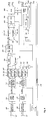
- FIG. 3 shows a basic circuit diagram of the basic structure of a device according to the invention.
- a basic image is generated using a basic video source 21, in the exemplary embodiment shown using a computer.
- the stereo image is recorded using a stereo source 23, in the exemplary embodiment shown using a stereo camera.
- the images are processed by means of a computer 21 which, in the exemplary embodiment shown, is also used to create the above-mentioned basic video image.
- the basic video image provided in the computer 21 via a VGA card 25 is fed to a stereo superimposition circuit 27.
- this stereo superimposition circuit 27 the two stereo source images are overlaid with the base image generated by the computer 21 and fed to the downstream monitor 1 via an output 29.
- an infrared transmitter 13 which is generally set up in the area of the monitor, is controlled via a synchronization line 31, via which shutter glasses 3 'which are actively working in the exemplary embodiment shown are now controlled, as is done in principle on the basis of the known method shown in FIG.
- This method can then be used to superimpose or superimpose the stereo images recorded live by the stereo source 23 consisting of two video cameras in a base image created by the computer.
- the exemplary embodiment according to FIG. 4 is explained in the event that the two stereo sources 23 support the digital serial D1 standard and are alternatively made available via a bus of a host computer.
- the graphic information of the basic video source is supplied via a standard VGA connector.
- the feature connector of the graphics card is not used.
- the two images of the stereo source 23 are present at the two inputs 23 ′ and 23 ′′, the data for the left image at the input 23 ′ and the data for the right image at the input 23 ′′ be fed to the stereo source of the circuit.
- the synchronization signals are first separated from the serial digital data stream in the ICs 100 and 200 for the left and the right stereo source image. Both IC's 100 and 200 each have a serial-parallel converter 130, 230 downstream. This creates a YUV data stream with a 27 MHz pixel rate.
- the fields in memory banks 301 and 302 and memory banks 305, 306 are then distributed separately for the left and right channels in a synchronization circuit 320, 330 in accordance with the synchronization signals.
- the memory banks 303 and 307 for the left and right channels, which are also provided, are required as buffers for the asynchronous reading process with 22.5 MHz.
- the image transmission to the host computer is controlled via a bus 310 via the synchronization circuits 320 and 330 (frame grabber and load function).
- the two channels are now combined to form a data stream in accordance with the two video images of the stereo image, the data rate doubling from 22.5 MHz to 45 MHz.
- a line multiplier 360 is provided for this.
- the output of the line multiplier 360 is followed by a line repeater 390 as an intermediate buffer.
- the line buffered in the line memory 390 is required in the FIR filter 400 provided below for the scaling.
- the FIR filter 400 is followed by a converter 410 in which a YUV / RGB conversion takes place.
- the FIR filter 400 and the converter 410 can also be combined into one stage.
- the two channels are then again divided into two paths 440, 460, which lead to output image memories 500 and 501 for the left channel and 510, 511 for the right channel.
- the two outputs of the output image memories 500, 501 and 510, 511 are followed by a look-up table 600 with two corresponding inputs connected to the output image memories, with which real-time manipulation of the digital video information can be carried out. So that z. B. set a gamma correction or implement a pseudo color display.
- the look-up table 600 is followed by a digital-to-analog converter 700, which can also be combined with the look-up table 600 to form a common module.
- the analog graphic information from that of the VGA card is finally mixed with the information in a discrete mixer 800.
- the mixing process is controlled by a timing generator 550.
- the timing generator 550 also serves to generate the synchronization signal for controlling the shutter glasses 3 '(FIG. 3).
- the timing generator 550 also has a further input 550 a for the H signals and an input 550 b for the V signals of the graphics card, not shown in the figure, which serves as a reference for the output timing.
- An 840 phase comparator and a VCO 850 i.e. a voltage-controlled oscillator, are used for the control.
- FIG. 4 also indicates that the timing generator 550 has a further output 550c, at which a synchronization output signal is present. which is required to synchronize the infrared transmitter 13 shown in FIG. 3 to control the shutter glasses 3 '.
Abstract
Description
Die Erfindung betrifft ein Verfahren sowie eine Vorrichtung zur Überlagerung von Stereo-Videobildern nach dem Oberbegriff des Anspruches 1 bzw. 8.8. The invention relates to a method and a device for superimposing stereo video images according to the preamble of
Es sind verschiedene Verfahren bekannt, stereografische Videobilder räumlich darzustellen. Bei den meisten Methoden wird der räumliche Bildeindruck dadurch erzeugt, daß dem linken und dem rechten Auge des Betrachters unterschiedliche Teilbilder gezeigt werden, die sich dadurch unterscheiden, daß zwischen den in den beiden Teilbildern sichtbaren Objekten eine tiefenabhängige Disparität besteht.Various methods are known for spatially displaying stereographic video images. In most methods, the spatial image impression is created by showing the left and right eyes of the viewer different partial images, which differ in that there is a depth-dependent disparity between the objects visible in the two partial images.
Bei einer häufig zur Wiedergabe von Stereobildern verwendeten Methode wird dafür gesorgt, daß das linke und das rechte Teilbild unterschiedlich polarisiert sind.In a method which is frequently used for the reproduction of stereo images, it is ensured that the left and right partial images are polarized differently.
Wie anhand von Figur 1 dargestellt ist, kann dies dadurch erreicht werden, daß beispielsweise vor dem Monitor 1 ein bildschirmfüllender LC-Shutter 2 angebracht wird, der synchron mit dem Bildwechsel nur für horizontal bzw. vertikal (oder auch linkszirkular bzw. rechtszirkular) polarisiertes Licht durchlässig geschaltet ist. Für die Beobachtung ist dann eine Polarisations-Brille 3 mit entsprechend unterschiedlich polarisierten Gläsern erforderlich. Dadurch läßt sich dann ein Stereo-Videobild 5 auf dem Monitor oder Fernseher 1 betrachten.As shown in FIG. 1, this can be achieved by, for example, attaching a screen-filling
Anstelle eines Monitors 1 können auch zwei Video-Projektoren verwendet werden, wobei durch vor den Projektoren angebrachte Polarisationsfilter - vergleichbar dem LC-Shutter 1 in dem bekannten Ausführungsbeispiel nach Figur 1 - eine unterschiedliche Polarsisation des linken und des rechten Teilbildes erzielbar ist. Für die Beobachtung ist wie beim Monitor-Shutter-Verfahren gemäß Figur 1 lediglich eine passive Brille mit entsprechend unterschiedlich polarisierten Gläsern erforderlich.Instead of a
Eine weitere bekannte Methode ist das Shutter-Brillen-Verfahren, welches anhand von Figur 2 dargestellt ist.Another known method is the shutter glasses method, which is shown with reference to FIG. 2.
Dabei wird ein Monitor oder ein Projektor 1 verwendet, der das linke und das rechte Teilbild in schnellem Wechsel zeigt. Um den Stereo-Effekt sichtbar zu machen, wird nunmehr dafür gesorgt, daß das linke Auge nur das linke und das rechte Auge nur das rechte Teilbild sieht. Der Beobachter muß dazu eine Shutter-Brille 3' tragen. Diese verfügt über LC-Gläser 11, die im Takt des Bildwechsels durchsichtig und undurchsichtig geschaltet werden. Es handelt sich also um eine aktive Brille, die aufgrund der Funktion der Brille größer, schwerer und teurer als eine passive Polarisationsbrille ausfällt und zudem entweder drahtgebunden oder über einen Sender angesteuert wird, wobei insbesondere bei einer drahtlosen mittels Senders und Empfängers arbeitenden Ansteuerung ferner eine Batterie für die Brille vorgesehen sein muß. Auch die Synchronisation mit dem Bildwechsel muß aktiv erfolgen, also über ein Kabel oder - was wesentlich bequemer ist - mit Hilfe eines Senders, beispielsweise eines Infrarot-Senders 13.Here, a monitor or a
Zur Vermeidung des Bildflimmerns wird häufig auch noch die Bildfrequenz verdoppelt, was jedoch eine schneller schaltende Shutter-Brille erforderlich macht.To avoid flicker, the frame rate is also often doubled, which, however, requires faster switching shutter glasses.
Bei Verwendung von Monitoren wird die zuletzt genannte Methode am häufigsten eingesetzt, da nur ein Standard-Monitor benötigt wird. Anders als bei der Eingangs erläuterten Polarisations-Methode mit linear polarisiertem Licht ist der Stereo-Effekt unabhängig von der Kopfneigung und vom Standort des Betrachters. Es können von daher auch mehrere Beobachter gleichzeitig teilnehmen und das Bildflimmern kann durch Frequenzverdopplung reduziert werden.When using monitors, the latter method is used most often, since only a standard monitor is required. Unlike the polarization method with linearly polarized light explained at the beginning, the stereo effect is independent of the head tilt and the position of the viewer. Therefore, several observers can participate at the same time and the image flicker can be reduced by doubling the frequency.
Bei den erläuterten und einigen weiteren ebenfalls bekannten Verfahren wird also immer aus zwei Teilbildern ein Stereobild erzeugt.In the case of the methods explained and some other likewise known methods, a stereo image is therefore always generated from two partial images.
Aufgabe der vorliegenden Erfindung ist es, ein verbessertes Verfahren sowie eine zugehörige verbesserte Vorrichtung zu schaffen, mittels der Stereo-Videobilder erzeugt, anderen Videobildern überlagert und betrachtet werden können.The object of the present invention is to provide an improved method and an associated improved device by means of which stereo video images can be generated, superimposed on other video images and viewed.
Die Aufgabe wird bezüglich des Verfahrens entsprechend den im Anspruch 1 und bezüglich der Vorrichtung ensprechend den im Anspruch 8 angegebenen Merkmalen gelöst. Vorteilhafte Ausgestaltungen der Erfindung sind in den Unteransprüchen angegeben.The task becomes corresponding with regard to the method corresponding to that in
Mittels der vorliegenden Erfindung wird es nunmehr erstmals möglich, ein Stereobildpaar in ein weiteres Videobild, insbesondere ein Computer-Grafik-Bild - nachfolgend zum Teil auch Basisbild genannt - einzublenden bzw. diesem zu überlagern. Dabei kann das Video- oder Basisbild ebenfalls stereografisch sein. Es sind also drei Videoquellen erforderlich, nämlich je eine Quelle für das linke Stereo-Teilbild, das rechte Stereo-Teilbild sowie das Basisbild, welchem das Stereobild überlagert werden soll. Im Falle eines Stereo-Basisbildes sind zudem neben der einen Quelle für das linke Stereo-Teilbild sowie eine Quelle für das rechte Stereo-Teilbild zwei weitere Quellen für das linke und das rechte Stereo-Basisbild erforderlich.By means of the present invention it is now possible for the first time to fade in or superimpose a pair of stereo images into a further video image, in particular a computer graphic image - hereinafter also referred to in part as a base image. The video or base image can also be stereographic. Three video sources are therefore required, namely one source each for the left stereo field, the right stereo field and the base picture on which the stereo picture is to be superimposed. In the case of a stereo base image, in addition to the one source for the left stereo sub-image and one source for the right stereo sub-image, two further sources are required for the left and the right stereo base image.
Die Einblendung bzw. Überlagerung kann auf verschiedene Arten geschehen. Möglich ist ein ![]()
![]()
![]()
![]()
Gemäß einer Ausführungsform der Erfindung ist es bei reduzierter Ortsauflösung möglich, daß die beiden Stereo-Teilbilder auch als gerades und ungerades Halbbild von einer interlaced Videoquelle (also eine Videoquelle, die die Bilder nach Art von zwei Halbbildern zusammensetzt) z. B. in Form eines Standard-Videorekorders zugespielt werden. Möglich ist es aber ebenso, daß als Quellen gespeicherte Bilder verwendet werden, die beispielsweise auf einer mittels Laser lesbaren Disk (CD) oder einer Festplatte eines Computers vorliegen.According to one embodiment of the invention, it is possible with reduced spatial resolution that the two stereo fields also as an even and odd field from an interlaced video source (i.e. a video source that combines the images in the manner of two fields) z. B. in the form of a standard video recorder. However, it is also possible for images stored as sources to be used which are present, for example, on a laser-readable disk (CD) or a hard disk of a computer.
In einer bevorzugten Ausführungsform der Erfindung ist vorgesehen, daß beispielsweise die von zwei synchron arbeitenden Videokameras stammenden Stereo-Teilbilder einer Computer-Graphik überlagert werden.In a preferred embodiment of the invention it is provided that, for example, the stereo partial images from two synchronously operating video cameras are superimposed on a computer graphic.
Mittels der Erfindung ist also die Überlagerung, Einblendung und Mischung von Stereobildern mit einem Nicht-Stereo-Basisbild oder einem stereografischen Basisbild möglich. Die Umsetzung und die Art der Visualisierung kann dabei mittels grundsätzlich bekannter Methoden erfolgen. Von daher können zur gemeinsamen Darstellen beispielsweise eine Computer-Graphik mit eingeblendeten Stereobildern die eingangs erläuterten Standard-Verfahren dienen, welche unter Verwendung von Shutter-Brillen oder Polarisationsbrillen arbeiten. Daneben sind aber genauso auch neuere, autostereoskopische Anzeigeeinrichtungen (Displays) einsetzbar.The invention therefore makes it possible to superimpose, fade in and mix stereo images with a non-stereo base image or a stereographic base image. The implementation and the type of visualization can be carried out using generally known methods. Therefore, for common display, for example a computer graphic with superimposed stereo images, the standard methods explained at the beginning can be used, which work using shutter glasses or polarizing glasses. In addition, however, newer, autostereoscopic display devices (displays) can also be used.
Die Erfindung weist insbesondere folgende Vorteile auf:
- Alle drei Quellen (im Falle eines Stereo-Basisbildes alle vier Quellen) können sowohl Standbilder als auch Bewegtbilder sein.
- Für die Stereo-Teilbilder können Halb- aber auch zwei Vollbilder verwendet werden, was wegen der höheren örtlichen Auflösung den Bildeindruck wesentlich verbessert.
- Eine weitere Verbesserung läßt sich dadurch realisieren, daß die Halbbilder mit Hilfe einer gefilterten Interpolation auf Vollbilder konvertiert werden.
- Die eingeblendeten Stereobilder können in ihrer Größe frei variiert werden.
- Der Ort der Einblendung des Stereobildes im Basisbild (oder in den Stereo-Basisbildern) kann frei gewählt werden.
- Die Einblendung kann dabei durch Mischen mit dem Basisbild im digitalen oder analogen Ver-arbeitungskanal umgesetzt werden.
- Mittels sog. Look-Up-Tabellen ist eine digitale Gamma-Korrektur sowie eine Falschfarbendarstellung möglich.
- All three sources (in the case of a stereo base picture, all four sources) can be both still pictures and moving pictures.
- For the stereo fields, fields can also be two full images are used, which significantly improves the image impression due to the higher local resolution.
- A further improvement can be achieved in that the fields are converted to frames with the aid of filtered interpolation.
- The size of the displayed stereo images can be varied freely.
- The location of the superimposition of the stereo image in the base image (or in the stereo base images) can be chosen freely.
- The overlay can be implemented by mixing with the basic image in the digital or analog processing channel.
- Using so-called look-up tables, digital gamma correction and false color display is possible.
Die Erfindung wird nachfolgend anhand eines Ausführungsbeispiels näher erläutert. Dabei zeigen im einzelnen
- Figur 1 :
- eine schematische Darstellung des Monitor-Shutter-Verfahrens nach dem Stand der Technik, bei welcher eine Kanaltrennung durch einen großen, vor dem Monitor angebrachten Plarisations-Shutter in Verbindung mit passiven Polarisationsbrillen erreichbar ist;
- Figur 2 :
- eine schematische Darstellung eines bekannten Shutter-Brillen-Verfahrens, bei welchem eine Kanaltrennung durch Verwendung aktiver Shutter-Brillen erreichbar ist;
- Figur 3 :
- eine schematische Darstellung einer erfindungsgemäßen Vorrichtung zur Erzeugung von Stereo-Überlagerungs-Bildern; und
- Figur 4 :
- ein Prinzipschaltbild eines Schaltplans für eine erfindungsgemäße Vorrichtung.
- Figure 1:
- is a schematic representation of the monitor-shutter method according to the prior art, in which a channel separation can be achieved by a large, arranged in front of the monitor Plarization Shutter in connection with passive polarizing glasses;
- Figure 2:
- a schematic representation of a known shutter glasses method, in which a channel separation can be achieved by using active shutter glasses;
- Figure 3:
- is a schematic representation of an inventive device for generating stereo overlay images; and
- Figure 4:
- a schematic diagram of a circuit diagram for a device according to the invention.
Anhand von Figur 3 ist ein Prinzipschaltbild über den grundsätzlichen Aufbau einer erfindungsgemäßen Vorrichtung gezeigt.3 shows a basic circuit diagram of the basic structure of a device according to the invention.
Bei dem Ausführungsbeispiel gemäß Figur 3 wird ein Basisbild mittels einer Basis-Videoquelle 21, im gezeigten Ausführungsbeispiel mittels eines Computers erzeugt.In the exemplary embodiment according to FIG. 3, a basic image is generated using a
Das Stereobild wird mittels einer Stereo-Quelle 23, im gezeigten Ausführungsbeispiel mittels einer Stereo-Kamera aufgenommen. Die Bilder werden mittels eines Computers 21 verarbeitet, der im gezeigten Ausführungsbeispiel gleichzeitig auch zur Erstellung des erwähnten Basis-Videobildes dient.The stereo image is recorded using a
Das im Computer 21 über eine VGA-Karte 25 bereitgestellte Basis-Videobild wird einer Stereo-Überlagerungsschaltung 27 zugeführt. In dieser Stereo-Überlagerungsschaltung 27 werden die beiden Stereo-Quellbilder mit dem vom Computer 21 erzeugten Basis-Bild überlagert und über einen Ausgang 29 dem nachgeschalteten Monitor 1 zugeführt.The basic video image provided in the
Über eine Synchronisationsleitung 31 wird dazu ein in der Regel im Bereich des Monitors aufgestellter Infrarot-Sender 13 angesteuert, worüber nunmehr eine im gezeigten Ausführungsbeispiel aktiv arbeitende Shutter-Brille 3' angesteuert wird, wie dies grundsätzlich anhand des von Figur 2 dargestellten bekannten Verfahrens erfolgt.For this purpose, an
Mittels dieses Verfahrens können dann in einem vom Computer erstellten Basisbild die von der aus zwei Videokameras bestehenden Stereo-Quelle 23 live aufgenommenen Stereobilder eingeblendet bzw. überlagert werden.This method can then be used to superimpose or superimpose the stereo images recorded live by the
Anhand von Figur 4 wird ein ensprechendes Prinzipschaltbild erläutert.A corresponding basic circuit diagram is explained with reference to FIG. 4.
Das Ausführungsbeispiel gemäß Figur 4 wird für den Fall erläutert, daß die beiden Stereoquellen 23 den digitalen seriellen D1-Standard unterstützen und alternativ über einen Bus eines Host-Rechners zur Verfügung gestellt werden. die Grafik-Information der Basis-Videoquelle wird über einen Standard-VGA-Stecker analog zugeführt. Dabei wird der Feature-Connector der Grafik-Karte nicht verwendet.The exemplary embodiment according to FIG. 4 is explained in the event that the two
Bei dem Prinzipschaltbild gemäß Figur 4 stehen die beiden Bilder der Stereo-Quelle 23 an den beiden Eingängen 23' und 23'' an, wobei am Eingang 23' die Daten beispielsweise für das linke und am Eingang 23'' die Daten für das rechte Bild der Stereo-Quelle der Schaltung zugeführt werden.In the basic circuit diagram according to FIG. 4, the two images of the
Aus dem seriellen digitalen Datenstrom werden zunächst in den IC's 100 und 200 für das linke wie das rechte Stereo-Quellbild die Synchronisationssignale abgetrennt. Beiden IC's 100 und 200 ist jeweils ein seriell-parallel-Wandler 130, 230 nachgeschaltet. Dadurch wird ein YUV-Datenstrom mit 27 MHz Pixelrate erzeugt.The synchronization signals are first separated from the serial digital data stream in the
Anschließend werden in einer Synchronisationsschaltung 320, 330 entsprechend den Synchronisations-Signalen die Halbbilder in Speicher-Bänke 301 und 302 und SpeicherBänke 305, 306 jeweils getrennt für den linken und rechten Kanal verteilt. Die ferner noch vorgesehenen Speicher-Bänke 303 bzw. 307 für den linken und rechten Kanal werden als Zwischenspeicher für den asynchron mit 22,5 MHz erfolgenden Auslesevorgang benötigt.The fields in
Ferner wird über die Synchronisationsschaltung 320 und 330 die Bildübertragung zum Host-Rechner über einen Bus 310 gesteuert (Frame-Grabber- und Load-Function).Furthermore, the image transmission to the host computer is controlled via a
Beim Auslesen der Speicher-Bänke 301 bis 303 und 305 bis 307 werden nun die beiden Kanäle entsprechend den beiden Videobildern des Stereobildes zu einem Datenstrom zusammengefaßt, wobei eine Verdopplung der Datenrate von 22,5 MHz auf 45 MHz erfolgt. Dazu ist ein Zeilenvervielfacher 360 vorgesehen.When the
Dem Ausgang des Zeilenvervielfachers 360 ist ein Zeilenwiederholer 390 als Zwischenpuffer nachgeschaltet. Die in dem Zeilenspeicher 390 zwischengespeicherte Zeile wird in dem nachfolgend vorgesehenen FIR-Filter 400 für die Skalierung benötigt.The output of the
Dem FIR-Filter 400 ist ein Konverter 410 nachgeschaltet, in dem eine YUV/RGB-Konvertierung stattfindet. Der FIR-Filter 400 und der Konverter 410 können auch zu einer Stufe zusammengefaßt sein.The
Anschließend werden die beiden Kanäle wieder in zwei Pfade 440, 460 aufgeteilt, die zu Ausgabe-Bildspeichern 500 und 501 für den linken und 510, 511 für den rechten Kanal führen. Den beiden Ausgängen der Ausgabe-Bildspeicher 500, 501 und 510, 511 ist eine Look-Up-Tabelle 600 mit zwei entsprechenden mit den Ausgabe-Bildspeichern verbundenen Eingängen nachgeschaltet, mit der eine Echtzeitmanipulation an den digitalen Video-Informationen vorgenommen werden kann. Damit läßt sich z. B. eine Gammakorrektur einstellen oder eine Pseudo-Farbdarstellung realisieren.The two channels are then again divided into two
Der Look-Up-Tabelle 600 ist ein Digital-Analog-Wandler 700 nachgeschaltet, der mit der Look-Up-Tabelle 600 auch zu einem gemeinsamen Baustein zusammengefaßt werden kann.The look-up table 600 is followed by a digital-to-
In einem letzten Schritt wird schließlich in einem diskret aufgebauten Mischer 800 die analoge Grafik-Information von der der VGA-Karte mit der Information gemischt. Die Steuerung des Mischvorganges erfolgt dabei durch einen Timing-Generator 550. Darüber können insbesondere die Lage und die Größe des Bildausschnittes eingestellt werden. Der Timing-Generator 550 dient ferner für die Erzeugung des Synchronisations-Signals zur Steuerung der Shutter-Brille 3' (Figur 3). Der Timing-Generator 550 weist ferner einen weiteren Eingang 550 a für die H-Signale und einen Eingang 550 b für die V-Signale der in Figur nicht weiter gezeigten Grafikkarte auf, die als Referenz für die AusgabeZeitsteuerung dient. Für die Regelung werden ein Phasenkomparator 840 und ein VCO 850, also ein spannungsgesteuerter Oszillator, verwendet.In a final step, the analog graphic information from that of the VGA card is finally mixed with the information in a
Schließlich ist in Figur 4 auch angedeutet, daß der Timing-Generator 550 einen weiteren Ausgang 550c aufweist, an welchem ein Synchronisations-Ausgangssignal ansteht, welches zur Synchronisation des in Figur 3 dargestellten Infrarot-Senders 13 zur Ansteuerung der Shutter-Brille 3' benötigt wird.Finally, FIG. 4 also indicates that the
Auch wenn abweichend vom gezeigten Ausführungsbeispiel als Basis-Videoquelle ein Stereobild verwendet wird, so ändert sich dadurch der grundsätzliche Aufbau der vorstehend erläuterten Schaltung nicht.Even if, in contrast to the exemplary embodiment shown, a stereo image is used as the basic video source, this does not change the basic structure of the circuit explained above.
Claims (21)
Applications Claiming Priority (2)
| Application Number | Priority Date | Filing Date | Title |
|---|---|---|---|
| DE19545356A DE19545356C2 (en) | 1995-12-05 | 1995-12-05 | Device for displaying stereo video images |
| DE19545356 | 1995-12-05 |
Publications (3)
| Publication Number | Publication Date |
|---|---|
| EP0777393A2 true EP0777393A2 (en) | 1997-06-04 |
| EP0777393A3 EP0777393A3 (en) | 1997-06-11 |
| EP0777393B1 EP0777393B1 (en) | 2001-05-30 |
Family
ID=7779246
Family Applications (1)
| Application Number | Title | Priority Date | Filing Date |
|---|---|---|---|
| EP96119299A Expired - Lifetime EP0777393B1 (en) | 1995-12-05 | 1996-12-02 | Method and apparatus for the superposition of stereoscopic video images |
Country Status (3)
| Country | Link |
|---|---|
| EP (1) | EP0777393B1 (en) |
| AT (1) | ATE201801T1 (en) |
| DE (2) | DE19545356C2 (en) |
Cited By (6)
| Publication number | Priority date | Publication date | Assignee | Title |
|---|---|---|---|---|
| GB2414883A (en) * | 2004-06-02 | 2005-12-07 | Seos Ltd | Apparatus for displaying images utilising liquid crystal shutter glasses |
| WO2010070567A1 (en) * | 2008-12-19 | 2010-06-24 | Koninklijke Philips Electronics N.V. | Method and device for overlaying 3d graphics over 3d video |
| JP2012530998A (en) * | 2009-06-24 | 2012-12-06 | ドルビー ラボラトリーズ ライセンシング コーポレイション | Incorporating 3D objects into stereoscopic images with relative depth |
| RU2562757C2 (en) * | 2010-04-18 | 2015-09-10 | АЙМАКС Юроп СА | Double superimposed projection |
| US9426441B2 (en) | 2010-03-08 | 2016-08-23 | Dolby Laboratories Licensing Corporation | Methods for carrying and transmitting 3D z-norm attributes in digital TV closed captioning |
| US9519994B2 (en) | 2011-04-15 | 2016-12-13 | Dolby Laboratories Licensing Corporation | Systems and methods for rendering 3D image independent of display size and viewing distance |
Families Citing this family (6)
| Publication number | Priority date | Publication date | Assignee | Title |
|---|---|---|---|---|
| ES2167203A1 (en) * | 2000-01-21 | 2002-05-01 | Univ Madrid Politecnica | Device for inserting stereoscopic video on the screen of a computer |
| DE102007039079B4 (en) * | 2007-08-16 | 2011-07-21 | VisuMotion GmbH, 07745 | Method and arrangement for the spatial representation of a scene with little or no illumination |
| WO2010151555A1 (en) | 2009-06-24 | 2010-12-29 | Dolby Laboratories Licensing Corporation | Method for embedding subtitles and/or graphic overlays in a 3d or multi-view video data |
| CN103765869B (en) | 2011-08-16 | 2017-12-12 | 图像影院国际有限公司 | Mixed image is decomposed and projection |
| WO2013057717A1 (en) | 2011-10-20 | 2013-04-25 | Imax Corporation | Distortion compensation for image projection |
| JP6147262B2 (en) | 2011-10-20 | 2017-06-14 | アイマックス コーポレイション | Invisibility or low perceptibility of image alignment in dual projection systems |
Family Cites Families (4)
| Publication number | Priority date | Publication date | Assignee | Title |
|---|---|---|---|---|
| US4851901A (en) * | 1986-09-03 | 1989-07-25 | Kabushiki Kaisha Toshiba | Stereoscopic television apparatus |
| US5142642A (en) * | 1988-08-24 | 1992-08-25 | Kabushiki Kaisha Toshiba | Stereoscopic television system |
| US5175616A (en) * | 1989-08-04 | 1992-12-29 | Her Majesty The Queen In Right Of Canada, As Represented By The Minister Of National Defence Of Canada | Stereoscopic video-graphic coordinate specification system |
| GB9121707D0 (en) * | 1991-10-12 | 1991-11-27 | British Aerospace | Improvements in computer-generated imagery |
-
1995
- 1995-12-05 DE DE19545356A patent/DE19545356C2/en not_active Expired - Fee Related
-
1996
- 1996-12-02 AT AT96119299T patent/ATE201801T1/en not_active IP Right Cessation
- 1996-12-02 DE DE59607000T patent/DE59607000D1/en not_active Expired - Lifetime
- 1996-12-02 EP EP96119299A patent/EP0777393B1/en not_active Expired - Lifetime
Non-Patent Citations (1)
| Title |
|---|
| None |
Cited By (13)
| Publication number | Priority date | Publication date | Assignee | Title |
|---|---|---|---|---|
| GB2414883A (en) * | 2004-06-02 | 2005-12-07 | Seos Ltd | Apparatus for displaying images utilising liquid crystal shutter glasses |
| CN102257825B (en) * | 2008-12-19 | 2016-11-16 | 皇家飞利浦电子股份有限公司 | For the method and apparatus covering 3D figure on 3D video |
| WO2010070567A1 (en) * | 2008-12-19 | 2010-06-24 | Koninklijke Philips Electronics N.V. | Method and device for overlaying 3d graphics over 3d video |
| CN102257825A (en) * | 2008-12-19 | 2011-11-23 | 皇家飞利浦电子股份有限公司 | Method and device for overlaying 3d graphics over 3d video |
| RU2537800C2 (en) * | 2008-12-19 | 2015-01-10 | Конинклейке Филипс Электроникс Н.В. | Method and device for overlaying three-dimensional graphics on three-dimensional video |
| AU2009329113B2 (en) * | 2008-12-19 | 2015-01-22 | Koninklijke Philips Electronics N.V. | Method and device for overlaying 3D graphics over 3D video |
| US10158841B2 (en) | 2008-12-19 | 2018-12-18 | Koninklijke Philips N.V. | Method and device for overlaying 3D graphics over 3D video |
| US9918069B2 (en) | 2008-12-19 | 2018-03-13 | Koninklijke Philips N.V. | Method and device for overlaying 3D graphics over 3D video |
| JP2012530998A (en) * | 2009-06-24 | 2012-12-06 | ドルビー ラボラトリーズ ライセンシング コーポレイション | Incorporating 3D objects into stereoscopic images with relative depth |
| US9215436B2 (en) | 2009-06-24 | 2015-12-15 | Dolby Laboratories Licensing Corporation | Insertion of 3D objects in a stereoscopic image at relative depth |
| US9426441B2 (en) | 2010-03-08 | 2016-08-23 | Dolby Laboratories Licensing Corporation | Methods for carrying and transmitting 3D z-norm attributes in digital TV closed captioning |
| RU2562757C2 (en) * | 2010-04-18 | 2015-09-10 | АЙМАКС Юроп СА | Double superimposed projection |
| US9519994B2 (en) | 2011-04-15 | 2016-12-13 | Dolby Laboratories Licensing Corporation | Systems and methods for rendering 3D image independent of display size and viewing distance |
Also Published As
| Publication number | Publication date |
|---|---|
| EP0777393B1 (en) | 2001-05-30 |
| DE59607000D1 (en) | 2001-07-05 |
| ATE201801T1 (en) | 2001-06-15 |
| DE19545356C2 (en) | 1998-04-16 |
| EP0777393A3 (en) | 1997-06-11 |
| DE19545356A1 (en) | 1996-05-09 |
Similar Documents
| Publication | Publication Date | Title |
|---|---|---|
| DE69733961T2 (en) | METHOD AND DEVICE FOR POSITIONING ADDITIONAL INFORMATION NEXT TO AN ADDITIONAL IMAGE IN A MULTI-PICTURE DISPLAY | |
| EP0737406B1 (en) | Method and device for displaying stereoscopic video images | |
| DE69632755T2 (en) | Device for generating computer-generated stereoscopic images | |
| DE19810062C2 (en) | Synchronization of left / right channel display and vertical refresh in stereoscopic multi-display computer graphics systems | |
| DE112011105224B4 (en) | Image information playback unit, image information playback apparatus, and synchronization control method | |
| EP0737405B1 (en) | Method and device for the recording and reproduction of stereoscopic video images | |
| DE69736506T2 (en) | Arrangement and method for generating display control signals adapted to the capabilities of the screen | |
| EP0584752B1 (en) | Method for generating a stereoscopic image representation | |
| EP0777393B1 (en) | Method and apparatus for the superposition of stereoscopic video images | |
| DE3623576A1 (en) | METHOD AND DEVICE FOR ELECTRONIC TRANSMISSION AND / OR RECORDING AND SUBSEQUENT PLAYBACK OF STEREOSCOPIC TELEVISION IMAGES | |
| DE19953596B4 (en) | Device for controlling LCD shutter glasses | |
| DE102005041249A1 (en) | Three-dimensional representable images creation method e.g. for TV transmission, involves registering input image signals and data with image type determined in accordance with image type data | |
| DE19542308A1 (en) | Three=dimensional video image representation method | |
| DE3808969C1 (en) | Device for reproducing three-dimensional pictures | |
| WO2021123365A1 (en) | Method for transferring at least one image content to at least one viewer | |
| WO2010022805A1 (en) | Display system | |
| EP1680929B1 (en) | Stereoprojection control system | |
| WO2006042706A1 (en) | Method for the creation of three-dimensionally representable images, and array for the three-dimensionally perceptible representation of such images | |
| EP2612502B1 (en) | Method for representing a plurality of image sequences | |
| DE4140502C1 (en) | Stereoscopic video recorder using half image memory - synchronising two video signals contg. spatial information to form complete picture | |
| DE102012002442B3 (en) | Method for processing monoscopic, stereoscopic or multiview image signals for e.g. factory planning application, involves performing computation of geometric distortion and determination of color independent-calibration parameter | |
| DE19624571C1 (en) | Optical media information display | |
| EP3907987A1 (en) | Method and device for projection of individual images for a plurality of viewers | |
| EP0975157B1 (en) | Television receiver with onscreen display | |
| EP1591883A2 (en) | Method and device for controlling a plurality of graphic displays |
Legal Events
| Date | Code | Title | Description |
|---|---|---|---|
| PUAI | Public reference made under article 153(3) epc to a published international application that has entered the european phase |
Free format text: ORIGINAL CODE: 0009012 |
|
| PUAL | Search report despatched |
Free format text: ORIGINAL CODE: 0009013 |
|
| AK | Designated contracting states |
Kind code of ref document: A2 Designated state(s): AT BE CH DE DK ES FI FR GB GR IE IT LI LU MC NL PT SE |
|
| AK | Designated contracting states |
Kind code of ref document: A3 Designated state(s): AT BE CH DE DK ES FI FR GB GR IE IT LI LU MC NL PT SE |
|
| RAP1 | Party data changed (applicant data changed or rights of an application transferred) |
Owner name: DEUTSCHE TELEKOM AG |
|
| 17P | Request for examination filed |
Effective date: 19970710 |
|
| RAP3 | Party data changed (applicant data changed or rights of an application transferred) |
Owner name: DEUTSCHE TELEKOM AG |
|
| 17Q | First examination report despatched |
Effective date: 19990427 |
|
| GRAG | Despatch of communication of intention to grant |
Free format text: ORIGINAL CODE: EPIDOS AGRA |
|
| GRAG | Despatch of communication of intention to grant |
Free format text: ORIGINAL CODE: EPIDOS AGRA |
|
| GRAH | Despatch of communication of intention to grant a patent |
Free format text: ORIGINAL CODE: EPIDOS IGRA |
|
| GRAH | Despatch of communication of intention to grant a patent |
Free format text: ORIGINAL CODE: EPIDOS IGRA |
|
| GRAA | (expected) grant |
Free format text: ORIGINAL CODE: 0009210 |
|
| AK | Designated contracting states |
Kind code of ref document: B1 Designated state(s): AT BE CH DE DK ES FI FR GB GR IE IT LI LU MC NL PT SE |
|
| PG25 | Lapsed in a contracting state [announced via postgrant information from national office to epo] |
Ref country code: NL Free format text: LAPSE BECAUSE OF FAILURE TO SUBMIT A TRANSLATION OF THE DESCRIPTION OR TO PAY THE FEE WITHIN THE PRESCRIBED TIME-LIMIT Effective date: 20010530 Ref country code: IE Free format text: LAPSE BECAUSE OF FAILURE TO SUBMIT A TRANSLATION OF THE DESCRIPTION OR TO PAY THE FEE WITHIN THE PRESCRIBED TIME-LIMIT Effective date: 20010530 Ref country code: FI Free format text: LAPSE BECAUSE OF FAILURE TO SUBMIT A TRANSLATION OF THE DESCRIPTION OR TO PAY THE FEE WITHIN THE PRESCRIBED TIME-LIMIT Effective date: 20010530 |
|
| REF | Corresponds to: |
Ref document number: 201801 Country of ref document: AT Date of ref document: 20010615 Kind code of ref document: T |
|
| REG | Reference to a national code |
Ref country code: CH Ref legal event code: EP |
|
| REF | Corresponds to: |
Ref document number: 59607000 Country of ref document: DE Date of ref document: 20010705 |
|
| REG | Reference to a national code |
Ref country code: IE Ref legal event code: FG4D Free format text: GERMAN |
|
| PG25 | Lapsed in a contracting state [announced via postgrant information from national office to epo] |
Ref country code: SE Free format text: LAPSE BECAUSE OF FAILURE TO SUBMIT A TRANSLATION OF THE DESCRIPTION OR TO PAY THE FEE WITHIN THE PRESCRIBED TIME-LIMIT Effective date: 20010830 Ref country code: PT Free format text: LAPSE BECAUSE OF FAILURE TO SUBMIT A TRANSLATION OF THE DESCRIPTION OR TO PAY THE FEE WITHIN THE PRESCRIBED TIME-LIMIT Effective date: 20010830 Ref country code: DK Free format text: LAPSE BECAUSE OF FAILURE TO SUBMIT A TRANSLATION OF THE DESCRIPTION OR TO PAY THE FEE WITHIN THE PRESCRIBED TIME-LIMIT Effective date: 20010830 |
|
| PG25 | Lapsed in a contracting state [announced via postgrant information from national office to epo] |
Ref country code: GR Free format text: LAPSE BECAUSE OF FAILURE TO SUBMIT A TRANSLATION OF THE DESCRIPTION OR TO PAY THE FEE WITHIN THE PRESCRIBED TIME-LIMIT Effective date: 20010831 |
|
| NLV1 | Nl: lapsed or annulled due to failure to fulfill the requirements of art. 29p and 29m of the patents act | ||
| GBV | Gb: ep patent (uk) treated as always having been void in accordance with gb section 77(7)/1977 [no translation filed] |
Effective date: 20010530 |
|
| PG25 | Lapsed in a contracting state [announced via postgrant information from national office to epo] |
Ref country code: ES Free format text: LAPSE BECAUSE OF FAILURE TO SUBMIT A TRANSLATION OF THE DESCRIPTION OR TO PAY THE FEE WITHIN THE PRESCRIBED TIME-LIMIT Effective date: 20011130 |
|
| PG25 | Lapsed in a contracting state [announced via postgrant information from national office to epo] |
Ref country code: MC Free format text: LAPSE BECAUSE OF NON-PAYMENT OF DUE FEES Effective date: 20011202 Ref country code: LU Free format text: LAPSE BECAUSE OF NON-PAYMENT OF DUE FEES Effective date: 20011202 Ref country code: AT Free format text: LAPSE BECAUSE OF NON-PAYMENT OF DUE FEES Effective date: 20011202 |
|
| REG | Reference to a national code |
Ref country code: CH Ref legal event code: NV Representative=s name: HUG INTERLIZENZ AG |
|
| EN | Fr: translation not filed | ||
| REG | Reference to a national code |
Ref country code: GB Ref legal event code: IF02 |
|
| REG | Reference to a national code |
Ref country code: GB Ref legal event code: 710B Free format text: EXTENSION APPLICATION: APPLICATION FOR EXTENSION OF THE PERIOD(S) PRESCRIBED BY RULE(S) SCHEDULE 4 PARA 2 FILED ON 03 DEC 2001. |
|
| REG | Reference to a national code |
Ref country code: GB Ref legal event code: 710B Free format text: FOLLOWING A REQUEST UNDER RULE 110(4) OF THE RULES 1995 TO EXTEND THE PERIOD FOR FILING A TRANSLATION OF THE SPECIFICATION, A TRANSLATION HAS NOW BEEN FILED IN ACCORDANCE WITH SECTION 77(6) (A). THIS PATENT WAS ANNOUNCED AS VOID IN THE PATENTS AND DESIGNS JOURNAL DATED 22.11.2001. THE PATENT IS NOW REINSTATED WITH A GRANT DATE EFFECTIVE IN THE UK OF 30.05.2001. |
|
| GBT | Gb: translation of ep patent filed (gb section 77(6)(a)/1977) |
Effective date: 20020117 |
|
| REG | Reference to a national code |
Ref country code: IE Ref legal event code: FD4D |
|
| REG | Reference to a national code |
Ref country code: FR Ref legal event code: RN |
|
| PLBE | No opposition filed within time limit |
Free format text: ORIGINAL CODE: 0009261 |
|
| STAA | Information on the status of an ep patent application or granted ep patent |
Free format text: STATUS: NO OPPOSITION FILED WITHIN TIME LIMIT |
|
| 26N | No opposition filed | ||
| REG | Reference to a national code |
Ref country code: FR Ref legal event code: FC |
|
| ET | Fr: translation filed | ||
| PGFP | Annual fee paid to national office [announced via postgrant information from national office to epo] |
Ref country code: IT Payment date: 20081223 Year of fee payment: 13 |
|
| PG25 | Lapsed in a contracting state [announced via postgrant information from national office to epo] |
Ref country code: IT Free format text: LAPSE BECAUSE OF NON-PAYMENT OF DUE FEES Effective date: 20091202 |
|
| REG | Reference to a national code |
Ref country code: CH Ref legal event code: PUE Owner name: IIINNOVATION S.A. Free format text: DEUTSCHE TELEKOM AG#FRIEDRICH-EBERT-ALLEE 140#53113 BONN (DE) -TRANSFER TO- IIINNOVATION S.A.#42-44, AVENUE DE LA GARE#1610 LUXEMBOURG (LU) Ref country code: CH Ref legal event code: NV Representative=s name: ZIMMERLI, WAGNER & PARTNER AG |
|
| REG | Reference to a national code |
Ref country code: GB Ref legal event code: 732E Free format text: REGISTERED BETWEEN 20110908 AND 20110914 |
|
| REG | Reference to a national code |
Ref country code: DE Ref legal event code: R081 Ref document number: 59607000 Country of ref document: DE Owner name: VIDISYS - VIDEO- UND DIGITAL-SYSTEME GMBH, DE Free format text: FORMER OWNER: DEUTSCHE TELEKOM AG, 53113 BONN, DE Effective date: 20110913 |
|
| REG | Reference to a national code |
Ref country code: FR Ref legal event code: TP Owner name: IIINOVATION S.A., LU Effective date: 20111102 |
|
| REG | Reference to a national code |
Ref country code: DE Ref legal event code: R082 Ref document number: 59607000 Country of ref document: DE Representative=s name: EISENFUEHR, SPEISER & PARTNER, DE |
|
| REG | Reference to a national code |
Ref country code: DE Ref legal event code: R082 Ref document number: 59607000 Country of ref document: DE Representative=s name: EISENFUEHR SPEISER PATENTANWAELTE RECHTSANWAEL, DE Effective date: 20121218 Ref country code: DE Ref legal event code: R082 Ref document number: 59607000 Country of ref document: DE Representative=s name: EISENFUEHR, SPEISER & PARTNER, DE Effective date: 20121218 Ref country code: DE Ref legal event code: R081 Ref document number: 59607000 Country of ref document: DE Owner name: VIDISYS - VIDEO- UND DIGITAL-SYSTEME GMBH, DE Free format text: FORMER OWNER: IIINNOVATION S.A., LUXEMBOURG, LU Effective date: 20121218 |
|
| REG | Reference to a national code |
Ref country code: FR Ref legal event code: TP Owner name: VIDISYS VIDEO UND DIGITALSYSTEME GMBH, DE Effective date: 20130402 |
|
| REG | Reference to a national code |
Ref country code: GB Ref legal event code: 732E Free format text: REGISTERED BETWEEN 20130418 AND 20130424 |
|
| REG | Reference to a national code |
Ref country code: CH Ref legal event code: NV Representative=s name: WAGNER PATENT AG, CH |
|
| REG | Reference to a national code |
Ref country code: FR Ref legal event code: PLFP Year of fee payment: 20 |
|
| PGFP | Annual fee paid to national office [announced via postgrant information from national office to epo] |
Ref country code: CH Payment date: 20151222 Year of fee payment: 20 Ref country code: GB Payment date: 20151221 Year of fee payment: 20 |
|
| PGFP | Annual fee paid to national office [announced via postgrant information from national office to epo] |
Ref country code: BE Payment date: 20151221 Year of fee payment: 20 Ref country code: FR Payment date: 20151218 Year of fee payment: 20 |
|
| PGFP | Annual fee paid to national office [announced via postgrant information from national office to epo] |
Ref country code: DE Payment date: 20160105 Year of fee payment: 20 |
|
| REG | Reference to a national code |
Ref country code: DE Ref legal event code: R071 Ref document number: 59607000 Country of ref document: DE |
|
| REG | Reference to a national code |
Ref country code: CH Ref legal event code: PL |
|
| REG | Reference to a national code |
Ref country code: GB Ref legal event code: PE20 Expiry date: 20161201 |
|
| PG25 | Lapsed in a contracting state [announced via postgrant information from national office to epo] |
Ref country code: GB Free format text: LAPSE BECAUSE OF EXPIRATION OF PROTECTION Effective date: 20161201 |