EP0777363A2 - Method for acknowledgement-based flow control - Google Patents
Method for acknowledgement-based flow control Download PDFInfo
- Publication number
- EP0777363A2 EP0777363A2 EP96308420A EP96308420A EP0777363A2 EP 0777363 A2 EP0777363 A2 EP 0777363A2 EP 96308420 A EP96308420 A EP 96308420A EP 96308420 A EP96308420 A EP 96308420A EP 0777363 A2 EP0777363 A2 EP 0777363A2
- Authority
- EP
- European Patent Office
- Prior art keywords
- transmission
- network
- delay
- latency characteristic
- function
- Prior art date
- Legal status (The legal status is an assumption and is not a legal conclusion. Google has not performed a legal analysis and makes no representation as to the accuracy of the status listed.)
- Granted
Links
Images


Classifications
-
- H—ELECTRICITY
- H04—ELECTRIC COMMUNICATION TECHNIQUE
- H04L—TRANSMISSION OF DIGITAL INFORMATION, e.g. TELEGRAPHIC COMMUNICATION
- H04L47/00—Traffic control in data switching networks
- H04L47/10—Flow control; Congestion control
- H04L47/28—Flow control; Congestion control in relation to timing considerations
- H04L47/283—Flow control; Congestion control in relation to timing considerations in response to processing delays, e.g. caused by jitter or round trip time [RTT]
-
- H—ELECTRICITY
- H04—ELECTRIC COMMUNICATION TECHNIQUE
- H04L—TRANSMISSION OF DIGITAL INFORMATION, e.g. TELEGRAPHIC COMMUNICATION
- H04L47/00—Traffic control in data switching networks
- H04L47/10—Flow control; Congestion control
-
- H—ELECTRICITY
- H04—ELECTRIC COMMUNICATION TECHNIQUE
- H04L—TRANSMISSION OF DIGITAL INFORMATION, e.g. TELEGRAPHIC COMMUNICATION
- H04L47/00—Traffic control in data switching networks
- H04L47/10—Flow control; Congestion control
- H04L47/26—Flow control; Congestion control using explicit feedback to the source, e.g. choke packets
- H04L47/267—Flow control; Congestion control using explicit feedback to the source, e.g. choke packets sent by the destination endpoint
-
- H—ELECTRICITY
- H04—ELECTRIC COMMUNICATION TECHNIQUE
- H04L—TRANSMISSION OF DIGITAL INFORMATION, e.g. TELEGRAPHIC COMMUNICATION
- H04L47/00—Traffic control in data switching networks
- H04L47/10—Flow control; Congestion control
- H04L47/35—Flow control; Congestion control by embedding flow control information in regular packets, e.g. piggybacking
Definitions
- the present invention relates to network connectivity, and more particularly to circuits and methods for intelligent acknowledgment-based flow control in processing system networks.
- a processing system network such as a computer network or a communications network, is a combination of two or more independent nodes that are capable of communicating with one another over a communications channel, path or link.
- a node may be an independent processing system, such as a conventional computer, or another processing system network.
- Nodes communicate with one another in order to share resources, such as databases and data files, software applications, hardware peripherals and communication links.
- Communication links are shared to enable two or more nodes that are not directly linked together to communicate through one or more intermediate nodes.
- Resource sharing generally involves the transference of large amounts of data.
- the data is typically divided into packets, frames, groups, etc. ("data packets"). Each data packet includes data and information necessary to route the same between two or more nodes.
- Networks traditionally belong in one of two general categories, namely, local area networks (“LANs”) and wide area networks (“WANs").
- a LAN is a group of communicating nodes that are located relatively close to one another, such as within the same building or building complex.
- a WAN is a collection of independent and distinct network nodes that cooperate over relatively long distances. Communication links between WAN nodes are routinely provided by third-party carriers, such as by long-distance telephone companies.
- Gateways such as routers, bridges or other suitable network portal devices, are used to couple LANs and WANs together (i.e., LAN-to-LAN, LAN-to-WAN and WAN-to-WAN).
- Gateways typically include control circuitry and a memory.
- the memory often includes the routing address for each LAN and each WAN coupled to the gateway, and also often includes the address of one or more of the nodes of each of the LANs and WANs. In the event that a particular node is itself a LAN or a WAN, the addresses of one or more of its nodes are also frequently stored in the memory.
- Level operations include data traffic flow control, sequencing, transmission error detection and correction, and the like.
- Level operations include data traffic flow control, sequencing, transmission error detection and correction, and the like.
- Network A, Network B and Network C serially coupled networks
- the data packets pass, like a baton in a relay race, from Network A to Network B to Network C until the same reaches a destination node.
- the destination node processes the received packets to determine whether they were correctly received.
- the destination node typically returns either an "ACK" signal, meaning that the transmission was received without error, or a "NAK” signal, meaning that the transmission was corrupt.
- the transmitting node In the event that the transmitting node receives an ACK signal, it typically purges the previously transmitted data packets from its transmission queue. Alternatively, if it receives a NAK signal, the transmitting node retransmits at least one of the one or more data packets to the destination node.
- Timers are typically used to verify the occurrence of an event within a prescribed time period, such as the reception of one or more data packets.
- the transmission node When the transmission node transmits a data packet, it starts a transmission timer that is set to expire if the destination node fails to respond in the form of an ACK or a NAK signal within a set period. Upon expiration, the transmission is reattempted and the transmission timer is reset.
- a common problem with transmission timer values however is that they fail to account for increases and decreases in network traffic (i.e., channel utilization). As traffic increases, timeouts tend to occur too soon. Conversely, as traffic decreases, timeouts tend to occur too late.
- a further problem associated with destination nodes is that after returning an ACK, they are often required to return one or more data packets to the transmission node. In other words, after processing the received data packets, the destination node transmits one or more resulting data packets to the transmission node thereby increasing overall network traffic.
- a solution to this latter identified problem is to delay return of a positive acknowledgment for a sufficient period for the destination node to process the received data packets, and to "piggyback" the ACK on a data packet to be returned.
- the destination node starts an acknowledgment timer that is set to expire if the destination node fails to generate a return data packet within a set period. Upon expiration, the destination node transmits the ACK signal.
- acknowledgment timers A common problem with acknowledgment timers is that they fail to account for series of data packets that are received at the destination node that do not generate return data. In other words, the acknowledgment timer tends to timeout repeatedly, unnecessarily delaying transmission of the ACK signal to the transmission node. Unfortunately, these repeated timeouts, when coupled with moderate to heavy traffic over a network, will slow down the transmission mode and may increase the occurrence of transmission timeouts and unnecessary retransmissions.
- a method for governing transmission of a signal by a transmission circuit over a network characterized by the steps of monitoring a latency characteristic, said latency characteristic being indicative, at least in part, of either an efficiency level associated with transmission of said signal by said transmission circuit, or a utilization level of the network; and adjusting a transmission delay of said transmission circuit for said signal over the network as a function of the latency characteristic to thereby manage the transmission delay.
- a management circuit for governing transmission of data packets and reception indicia by a transmission circuit over a network, characterized by detector circuitry operative to monitor a first latency characteristic of the network, said latency characteristic being indicative, at least in part, of a utilization level of the network, and to monitor a second latency characteristic being indicative, at least in part, of an efficiency level associated with transmission of the reception indicia by said transmission circuit; and control circuitry, associated with said detector circuitry and said transmission circuit, operative to adjust a retransmission delay of said transmission circuit of said data packets over the network as a function of the first latency characteristic to thereby allow said management circuit to manage the retransmission delay as a function of said utilization level of said network, and adjust a transmission delay of said transmission circuit of the reception indica over the network as a function of said second latency characteristic to thereby allow said management circuit to manage said transmission delay as a function of the efficiency level associated with said transmission circuit.
- TCP/IP is a known set of protocols developed to link dissimilar computers across many kinds of networks.
- TCP/IP is used herein for illustrative purposes only.
- the principles of the present invention may be implemented in accordance with any suitable acknowledgment-based data packet transmission scheme, including open systems interconnection (OSI), X.25, and the like.
- OSI open systems interconnection
- X.25 X.25
- Exemplary network 100 includes a plurality of interconnected nodes 105.
- a first set of nodes 105 form a first sub-network 110a, while a second set of nodes 105 form a second sub-network 110b.
- Exemplary sub-networks 110 are coupled via an exemplary gateway 115 (i.e., router, bridge or other suitable portal device).
- Gateway 115 may suitably be one of a core gateway or a non-core gateway.
- a core gateway includes information about the structure of network 100, whereas a non-core gateway includes limited or incomplete routing information, i.e., knowledge regarding one or more routes to a core gateway, but no knowledge about routing beyond the same.
- Core gateways typically store routing information in one or more routing tables. Each node 105 is required only to know a specific route to its local gateway 115. A data packet transmitted between two remotely located nodes is accordingly passed from one gateway to another until the same reaches a destination node.
- a routing table may suitably be programmer defined or developed dynamically (i.e., gateway queries neighboring gateways or the like for routing information).
- a given gateway may suitably include routing information for directly attached networks and general knowledge for routing traffic to remote networks. If a gateway cannot resolve a particular routing address, it broadcasts a request seeking assistance concerning the same to other gateways.
- a data packet is forwarded between locations spanning a plurality of sub-network environments, it is processed to determine the address of its destination location or, possibly, intermediate locations.
- the data packet is suitably encased or wrapped in a data envelope.
- the data envelope such as a file transfer protocol frame, typically includes a header having routing and transmission information.
- a TCP header for example, provides end-to-end transmission confirmation or acknowledgment.
- Exemplary network 100 includes a plurality of nodes 105, each of which is coupled locally to a suitable sub-network 110.
- a first node 105a operating as an internet protocol (IP) host, transmits an exemplary data packet 205 to a destination node 105n using an IP addressing scheme.
- IP internet protocol
- a first sub-network 110a processes data packet 205 and determines that destination node 105n is not local. In response thereto, an IP header is added to data packet 205.
- the IP header includes a global IP address for a second sub-network 110n.
- Gateway 115 routes data packet 205 based on the address of second sub-network 110n.
- Second sub-network 110n determines if the address of destination node 105n is local or remote. If the same is local, as illustrated, the data envelope is stripped off and data packet 205 is routed to destination node 105n.
- network 110n would suitably determine the address of the next network element and add its address to the existing IP data packet.
- that element received the data envelope containing the IP data packet, it would strip off the header designating its own address, and go through the same process as the previous network did, determining whether the destination address was local, and if not, packaging the IP data packet within another addressing header for the next network element. This process would continue until the data packet was finally routed to the destination address.
- first node 105a is further operative to retransmit data packet 205 in response to a transmission timeout.
- Destination node 105n is operative in accordance with TCP to verify and, preferably, correct received data packet 205, if necessary and possible. If correct, destination node 105n returns an acknowledgment signal to first node 105a, otherwise it may suitably return a negative acknowledgment.
- Destination node 105n is also preferably operative to suitably use an acknowledgment timer to measure an interval of elapsed time with respect to the reception of data packet 205.
- destination node piggy-backs an acknowledgment, such as an ACK, to at least one return data packet.
- Destination node 105n is preferably further operative to transmit the acknowledgment alone to first node 105a in response to an acknowledgment timeout.
- Exemplary transmission timer values may suitably depend, without limitation, upon one or more of the following:
- First node 105a is operative in accordance with the illustrated embodiment to monitor the frequency of transmission timeout occurrences. If the same compares unfavourably with a threshold, then first node 105a is preferably operative to modify the timeout function (e.g., change the timeout threshold, slow the timer or clock, etc.), temporarily disable the timeout function, temporarily disable the acknowledgment requirement, or the like.
- “Disable,” as the term is used herein, includes detach, disassociate, disconnect, disengage, impair, incapacitate, separate or the like. An important aspect of the illustrated embodiment is the improved efficiency of data packet transference.
- Destination node 105n is operative in accordance with the illustrated embodiment to monitor the frequency of acknowledgment timeout occurrences. If the same compares unfavourably with a threshold, then destination node 105n is preferably operative to modify the timeout function (e.g., change the timeout threshold, slow the timer or clock, etc.), temporarily disable the timeout function, temporarily disable the acknowledgment requirement, or the like.
- Another important aspect of the illustrated embodiment is the improved efficiency of acknowledgment transference.
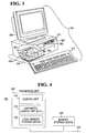
- Processing system 105 is capable of functioning as a node within either of the exemplary processing system networks of Figs. 1 or 2.
- Processing system 105 includes a monitor 305, a housing 310 and a keyboard 315.
- Housing 310 includes a hard disk drive 320 and a floppy disk drive 325.
- Hard disk drive 320 is suitable to provide fast access storage and retrieval.
- Floppy disk drive 325 is operative to receive, read or write to external disks, and may suitably be replaced by or combined with other conventional structures for transferring data or instructions, including tape and compact disc drives, telephony systems and devices (including telephone, video phone, facsimile or the like), message paging, network communication ports and the like.
- Housing 310 is partially cut-away to illustrate a battery 330, a clock 335, a processor 340 and a detached local memory 345, all of which are suitably housed therein.
- processing system 105 is illustrated having a single processor, a single hard disk drive and a single local memory, processing system 105 may suitably be equipped with any multitude or combination of processors or storage devices. Processing system 105 may, in point of fact, be replaced by, or combined with, any suitable processing system operative in accordance with the principles of the present invention, including video phones, telephones, televisions, pagers, sophisticated calculators, and hand-held, laptop/notebook, mini, mainframe and super computers, as well as processing system network combinations of the same.
- Microprocessing system 400 includes a processor 340 coupled via data bus 405 with a detached local memory 345.
- Memory 345 is operative to store data or instructions, which processor 340 is operative to retrieve and execute.
- Processor 340 includes a control unit 410, an arithmetic and logic unit (ALU) 415, and a internal memory 420 (e.g., stackable cache, a plurality of registers, etc.).
- Control unit 410 is suitably operative to fetch ones of the instructions from memory 345.
- ALU 415 is suitably operative to perform a plurality of operations, such as addition and Boolean AND, needed to carry out those instructions.
- Internal memory 420 is suitably operative to provide local high speed storage used to store temporary results and control information.
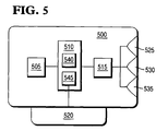
- Interface 500 includes an illustrative memory 505, a management circuit 510, a transmission circuit 515, an illustrative expansion bus connector 520, an illustrative connector for twisted-pair wire 525, an illustrative coaxial cable connector 530, and an illustrative transceiver connector 535.
- Management circuit 510 includes detector circuitry 540 and control circuitry 545.
- Interface 500 may suitably be coupled with exemplary processing system 105 of Fig. 3.
- Management circuit 510 is operative to govern transmission of one or more of a plurality of data packets, as well as reception indicia, such as ACKs and NAKs, by transmission circuit 515 over a network, such as network 100 of Figs. 1 and 2.
- the management circuit 510 comprises detector circuitry 540 and control circuitry 545.
- Detector circuitry 540 is operative to monitor a first latency characteristic of the network.
- the first latency characteristic is indicative or representative of, at least in part, a utilization level of the network.
- the utilization level of the network is important with respect to data packet transmission, in general, and to data packet retransmission, more specifically. As has been discussed herein, the threshold associated with a transmission timer is critical to efficient retransmission.
- Detector circuitry 540 is further operative to monitor a second latency characteristic.
- the second latency characteristic is indicative of, at least in part, an efficiency level associated with transmission of the reception indicia by transmission circuit 515.
- the efficiency level associated with the transmission of the reception indicia is important with respect to data packet acknowledgment, in general, and to positive acknowledgment and ACK piggybacking, more specifically. As discussed above, the threshold associated with an acknowledgment timer is critical to efficient data packet acknowledgment.
- Control circuitry 545 is associated with both detector circuitry 540 and transmission circuit 515. Control circuitry 545 is operative to suitably adjust a retransmission delay associated with transmission of the data packets over the network.
- the retransmission delay is the time interval between transmission and subsequent retransmission of one or more data packets. The adjustment is performed as a function of the first latency characteristic. This suitably enables or allows management circuit 510 to manage the retransmission delay as a function of the utilization level of the network.
- Control circuitry 545 is further operative to suitably adjust a transmission delay associated with transmission of the reception indica over the network.
- the transmission delay is the time interval between reception of a data packet and the eventual transmission of the reception indicia without piggybacking a return data packet.
- the adjustment is performed as a function of the second latency characteristic. This suitably enables management circuit 510 to manage the transmission delay as a function of the efficiency level associated with transmission circuit 515.
- control circuitry 545 may suitably use principles of applied mathematical theories, including statistics, stochastic modelling, chaos theory, standard deviation, probability theory, permutations and combinations, frequency, or the like. Further, in deriving the first measurable characteristic, in addition to the use of timers, clocks and the like, any physically sensible characteristic or aspect of the network impacting communication throughput may suitably be used (e.g., communication channel utilization indicia).
- network interface 500 is used to illustrate one circuit embodiment of the present invention
- other circuit configurations may suitably be implemented in other processing systems, nodes, gateways or the like.
- the above-identified circuits and circuitry, as well as microprocessing system 400 of Fig. 4 may suitably be replaced by or combined with programmable logic devices, such as PALs (programmable array logic) and PLAs (programmable logic arrays), DSPs (digital signal processors), FPGAs (field programmable gate arrays), ASICs (application specific integrated circuits), VLSIs (very large scale integrated circuits) or the like.
- PALs programmable array logic
- PLAs programmable logic arrays
- DSPs digital signal processors
- FPGAs field programmable gate arrays
- ASICs application specific integrated circuits
- VLSIs very large scale integrated circuits
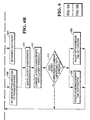
- FIG. 6 a flow diagram is illustrated for performing intelligent acknowledgment-based flow control in accordance with the principles of the present invention.
- the discussion of Fig. 6 is made with reference to Fig. 5.
- the management circuit 510 and the transmission circuit 515 could also be located in nodes.
- the transmission delay represents an elapsed time interval with respect to a received data packet.
- Detector circuitry 540 is operative to derive the latency characteristic as a function of the comparison (process step 610), and to compare the same with a latency threshold (process step 612), such as a maximum frequency of occurrence, for example.
- control circuitry 545 is operative to adjust or modify the acknowledgment timeout function (e.g., change the timeout threshold, slow the timer or clock, etc.), temporarily disable the same, temporarily disable the acknowledgment requirement, or the like (process step 616), thereby improving the overall efficiency of acknowledgment transference.
- the acknowledgment timeout function e.g., change the timeout threshold, slow the timer or clock, etc.
- management circuit 510 is operative to monitor the latency characteristic, and to adjust the transmission delay of the transmission of the reception indicia over the network. This is preferably accomplished as a function of the latency characteristic.
- the transmission circuit 515 is enabled, a retransmission timer is reset and the retransmission timer begins generating a retransmission delay (process step 620).
- the retransmission delay represents an elapsed time interval with respect to transmission of the data packet without receipt of reception indicia, such as an acknowledgment signal, for example.
- a determination is made as to whether the retransmission delay compares unfavourably with a retransmission threshold (decision step 622).
- Detector circuitry 540 is operative to derive the latency characteristic as a function of the comparison (process step 610), and to compare the same with a latency threshold (process step 612), such as a maximum frequency of occurrence, for example.
- control circuitry 545 is operative to adjust or modify the retransmission timeout function (e.g., change the timeout threshold, slow the timer or clock, etc.), temporarily disable the same, temporarily disable the retransmission requirement, or the like (process step 626), thereby improving the overall efficiency of data packet retransmission.
- the retransmission timeout function e.g., change the timeout threshold, slow the timer or clock, etc.
- An exemplary software embodiment includes a plurality of instructions stored to a conventional storage medium.
- the instructions are readable and executable by a suitable processor.
- the instructions upon execution, operate to control the processor to route data packets through a processing system network in accordance with the present invention.
- Preferred storage media include without limitation, magnetic, optic, and semiconductor, as well as suitable combinations thereof.
- a preferred software embodiment for governing transmission of reception indicia by a transmission circuit forms a portion of NCR's S TARGROUP TM LAN Manager for UNIXTM -- OSI Transport Version, which is available from NCR Corperation in Dayton, Ohio.
Abstract
- (a) monitor a first latency characteristic of the network (100) being indicative, at least in part, of a utilization level of the network (100); and
- (b) monitor a second latency characteristic being indicative, at least in part, of an efficiency level associated with transmission of the reception indicia by the transmission circuit (515).
- (a) adjust a retransmission delay of data packets (205) over the network (100) as a function of the first latency characteristic, thereby allowing the management circuit (510) to manage the retransmission delay as a function of the utilization level of said network (100); and
- (b) adjust a transmission delay of reception indicia over the network (100) as a function of the second latency characteristic to thereby allow the management circuit (510) to manage the transmission delay as a function of the efficiency level associated with the transmission circuit (515).
Description
- The present invention relates to network connectivity, and more particularly to circuits and methods for intelligent acknowledgment-based flow control in processing system networks.
- A processing system network, such as a computer network or a communications network, is a combination of two or more independent nodes that are capable of communicating with one another over a communications channel, path or link. A node may be an independent processing system, such as a conventional computer, or another processing system network.
- Nodes communicate with one another in order to share resources, such as databases and data files, software applications, hardware peripherals and communication links. Communication links are shared to enable two or more nodes that are not directly linked together to communicate through one or more intermediate nodes. Resource sharing generally involves the transference of large amounts of data. The data is typically divided into packets, frames, groups, etc. ("data packets"). Each data packet includes data and information necessary to route the same between two or more nodes.
- Networks traditionally belong in one of two general categories, namely, local area networks ("LANs") and wide area networks ("WANs"). A LAN is a group of communicating nodes that are located relatively close to one another, such as within the same building or building complex. A WAN, on the other hand, is a collection of independent and distinct network nodes that cooperate over relatively long distances. Communication links between WAN nodes are routinely provided by third-party carriers, such as by long-distance telephone companies. Gateways, such as routers, bridges or other suitable network portal devices, are used to couple LANs and WANs together (i.e., LAN-to-LAN, LAN-to-WAN and WAN-to-WAN). The conventional approach is to use the gateway as a junction point through which data packets received from a source network are routed to one or more destination networks. Gateways typically include control circuitry and a memory. The memory often includes the routing address for each LAN and each WAN coupled to the gateway, and also often includes the address of one or more of the nodes of each of the LANs and WANs. In the event that a particular node is itself a LAN or a WAN, the addresses of one or more of its nodes are also frequently stored in the memory.
- Communication between networks and nodes involves level operations. Level operations include data traffic flow control, sequencing, transmission error detection and correction, and the like. For example, consider three serially coupled networks (i.e., Network A, Network B and Network C) in which one or more data packets are transmitted from a Network A node to a Network C node. By definition, the data packets pass, like a baton in a relay race, from Network A to Network B to Network C until the same reaches a destination node. The destination node processes the received packets to determine whether they were correctly received. In response thereto, the destination node typically returns either an "ACK" signal, meaning that the transmission was received without error, or a "NAK" signal, meaning that the transmission was corrupt. In the event that the transmitting node receives an ACK signal, it typically purges the previously transmitted data packets from its transmission queue. Alternatively, if it receives a NAK signal, the transmitting node retransmits at least one of the one or more data packets to the destination node.
- Timers are typically used to verify the occurrence of an event within a prescribed time period, such as the reception of one or more data packets. When the transmission node transmits a data packet, it starts a transmission timer that is set to expire if the destination node fails to respond in the form of an ACK or a NAK signal within a set period. Upon expiration, the transmission is reattempted and the transmission timer is reset. A common problem with transmission timer values however is that they fail to account for increases and decreases in network traffic (i.e., channel utilization). As traffic increases, timeouts tend to occur too soon. Conversely, as traffic decreases, timeouts tend to occur too late. A further problem associated with destination nodes, is that after returning an ACK, they are often required to return one or more data packets to the transmission node. In other words, after processing the received data packets, the destination node transmits one or more resulting data packets to the transmission node thereby increasing overall network traffic.
- A solution to this latter identified problem is to delay return of a positive acknowledgment for a sufficient period for the destination node to process the received data packets, and to "piggyback" the ACK on a data packet to be returned. Typically, when the destination node receives a data packet, it starts an acknowledgment timer that is set to expire if the destination node fails to generate a return data packet within a set period. Upon expiration, the destination node transmits the ACK signal. A common problem with acknowledgment timers is that they fail to account for series of data packets that are received at the destination node that do not generate return data. In other words, the acknowledgment timer tends to timeout repeatedly, unnecessarily delaying transmission of the ACK signal to the transmission node. Unfortunately, these repeated timeouts, when coupled with moderate to heavy traffic over a network, will slow down the transmission mode and may increase the occurrence of transmission timeouts and unnecessary retransmissions.
- There accordingly exists a need in the art to effectively limit the occurrence of acknowledgment-based timeouts, particularly, those timeouts resulting from increased network traffic. There exists a further need in the art to more efficiently retransmit lost data packet transmissions that occur during intervals of decreased network traffic. There exists a still further need in the art to identify series of received data packets that will likely not return data to a transmitting node, and to suitably modify acknowledgment timers to more efficiently acknowledge data packet reception.
- It is an object of the present invention to dynamically and adaptively improve the efficiency of data packet transference in order to address the above discussed deficiencies.
- According to one aspect of the present invention there is provided a method for governing transmission of a signal by a transmission circuit over a network, characterized by the steps of monitoring a latency characteristic, said latency characteristic being indicative, at least in part, of either an efficiency level associated with transmission of said signal by said transmission circuit, or a utilization level of the network; and adjusting a transmission delay of said transmission circuit for said signal over the network as a function of the latency characteristic to thereby manage the transmission delay.
- According to another aspect of the present invention there is provided a management circuit for governing transmission of data packets and reception indicia by a transmission circuit over a network, characterized by detector circuitry operative to monitor a first latency characteristic of the network, said latency characteristic being indicative, at least in part, of a utilization level of the network, and to monitor a second latency characteristic being indicative, at least in part, of an efficiency level associated with transmission of the reception indicia by said transmission circuit; and control circuitry, associated with said detector circuitry and said transmission circuit, operative to adjust a retransmission delay of said transmission circuit of said data packets over the network as a function of the first latency characteristic to thereby allow said management circuit to manage the retransmission delay as a function of said utilization level of said network, and adjust a transmission delay of said transmission circuit of the reception indica over the network as a function of said second latency characteristic to thereby allow said management circuit to manage said transmission delay as a function of the efficiency level associated with said transmission circuit.
- One embodiment of the present invention will now be described by way of example with reference to the accompanying drawings in which:-
- Fig. 1 is a block diagram of the architectural structure of an exemplary transport control protocol/internet protocol (TCP/IP) network;
- Fig. 2 is a block diagram for routing one or more data packets between first and second locations in another exemplary processing system network;
- Fig. 3 is an isometric view of an exemplary processing system capable of functioning as a node within a processing system network;
- Fig. 4 is a block diagram of an exemplary microprocessing system that may suitably be implemented in the processing system of Fig. 3;
- Fig. 5 is a high-level block diagram of an exemplary network interface in accordance with the principles of the present invention; and
- Fig. 6 is a flow diagram for performing intelligent acknowledgment-based flow control in accordance with the principles of the present invention.
- Referring now to Fig. 1, a block diagram of the architectural structure of an exemplary TCP/
IP network 100 is illustrated. TCP/IP is a known set of protocols developed to link dissimilar computers across many kinds of networks. TCP/IP is used herein for illustrative purposes only. In point of fact, the principles of the present invention may be implemented in accordance with any suitable acknowledgment-based data packet transmission scheme, including open systems interconnection (OSI), X.25, and the like. "Include," as the term is used herein, means "include without limitation." -
Exemplary network 100 includes a plurality ofinterconnected nodes 105. A first set ofnodes 105 form afirst sub-network 110a, while a second set ofnodes 105 form asecond sub-network 110b. Exemplary sub-networks 110 are coupled via an exemplary gateway 115 (i.e., router, bridge or other suitable portal device). "Or" as used herein means "and/or." Gateway 115 may suitably be one of a core gateway or a non-core gateway. A core gateway includes information about the structure ofnetwork 100, whereas a non-core gateway includes limited or incomplete routing information, i.e., knowledge regarding one or more routes to a core gateway, but no knowledge about routing beyond the same. - Core gateways typically store routing information in one or more routing tables. Each
node 105 is required only to know a specific route to itslocal gateway 115. A data packet transmitted between two remotely located nodes is accordingly passed from one gateway to another until the same reaches a destination node. - A routing table may suitably be programmer defined or developed dynamically (i.e., gateway queries neighboring gateways or the like for routing information). A given gateway may suitably include routing information for directly attached networks and general knowledge for routing traffic to remote networks. If a gateway cannot resolve a particular routing address, it broadcasts a request seeking assistance concerning the same to other gateways.
- In general, as a data packet is forwarded between locations spanning a plurality of sub-network environments, it is processed to determine the address of its destination location or, possibly, intermediate locations. In response thereto, the data packet is suitably encased or wrapped in a data envelope. The data envelope, such as a file transfer protocol frame, typically includes a header having routing and transmission information. A TCP header, for example, provides end-to-end transmission confirmation or acknowledgment.
- Referring next to Fig. 2, a block diagram for routing one or more data packets between first and second locations in an exemplary TCP/
IP network 100 is illustrated in accordance with the present invention.Exemplary network 100 includes a plurality ofnodes 105, each of which is coupled locally to a suitable sub-network 110. Afirst node 105a, operating as an internet protocol (IP) host, transmits anexemplary data packet 205 to adestination node 105n using an IP addressing scheme. - A
first sub-network 110a processesdata packet 205 and determines thatdestination node 105n is not local. In response thereto, an IP header is added todata packet 205. The IP header includes a global IP address for asecond sub-network 110n.Gateway 115routes data packet 205 based on the address ofsecond sub-network 110n.Second sub-network 110n determines if the address ofdestination node 105n is local or remote. If the same is local, as illustrated, the data envelope is stripped off anddata packet 205 is routed todestination node 105n. - In the event that
destination node 105n was not local,network 110n would suitably determine the address of the next network element and add its address to the existing IP data packet. When that element received the data envelope containing the IP data packet, it would strip off the header designating its own address, and go through the same process as the previous network did, determining whether the destination address was local, and if not, packaging the IP data packet within another addressing header for the next network element. This process would continue until the data packet was finally routed to the destination address. - In the illustrated embodiment,
first node 105a is further operative to retransmitdata packet 205 in response to a transmission timeout. A "timeout," as the term is used herein, includes any suitable comparison between a threshold and a timer or clock value that yields a particular result.Destination node 105n is operative in accordance with TCP to verify and, preferably, correct receiveddata packet 205, if necessary and possible. If correct,destination node 105n returns an acknowledgment signal tofirst node 105a, otherwise it may suitably return a negative acknowledgment. -
Destination node 105n is also preferably operative to suitably use an acknowledgment timer to measure an interval of elapsed time with respect to the reception ofdata packet 205. "Measure," as used herein, includes compare, count, equate, evaluate, gauge, survey, quantify, weigh or the like. In the event that theprocessing data packet 205 generates or results in one or more data packets to be returned tofirst node 105a, destination node piggy-backs an acknowledgment, such as an ACK, to at least one return data packet.Destination node 105n is preferably further operative to transmit the acknowledgment alone tofirst node 105a in response to an acknowledgment timeout. - Exemplary transmission timer values may suitably depend, without limitation, upon one or more of the following:
- (a) round trip propagation delay of the signal (usually a small value, except for very long and very high-speed circuits);
- (b) processing time at the receiver (including queuing time of the data packet);
- (c) transmission time of the acknowledging signal or frame; or
- (d) possible queue and processing time at the transmitter when it receives the acknowledgment.
- Recall that heavy network traffic may delay receipt of the acknowledgment signal by first node 105b, thereby causing a timeout and retransmission of
data packet 205.First node 105a is operative in accordance with the illustrated embodiment to monitor the frequency of transmission timeout occurrences. If the same compares unfavourably with a threshold, thenfirst node 105a is preferably operative to modify the timeout function (e.g., change the timeout threshold, slow the timer or clock, etc.), temporarily disable the timeout function, temporarily disable the acknowledgment requirement, or the like. "Disable," as the term is used herein, includes detach, disassociate, disconnect, disengage, impair, incapacitate, separate or the like. An important aspect of the illustrated embodiment is the improved efficiency of data packet transference. -
Destination node 105n is operative in accordance with the illustrated embodiment to monitor the frequency of acknowledgment timeout occurrences. If the same compares unfavourably with a threshold, thendestination node 105n is preferably operative to modify the timeout function (e.g., change the timeout threshold, slow the timer or clock, etc.), temporarily disable the timeout function, temporarily disable the acknowledgment requirement, or the like. Another important aspect of the illustrated embodiment is the improved efficiency of acknowledgment transference. - Referring to Fig. 3, an isometric view of an
exemplary processing system 105 is illustrated.Processing system 105 is capable of functioning as a node within either of the exemplary processing system networks of Figs. 1 or 2.Processing system 105 includes amonitor 305, ahousing 310 and a keyboard 315. -
Housing 310 includes ahard disk drive 320 and afloppy disk drive 325.Hard disk drive 320 is suitable to provide fast access storage and retrieval.Floppy disk drive 325 is operative to receive, read or write to external disks, and may suitably be replaced by or combined with other conventional structures for transferring data or instructions, including tape and compact disc drives, telephony systems and devices (including telephone, video phone, facsimile or the like), message paging, network communication ports and the like. -
Housing 310 is partially cut-away to illustrate abattery 330, aclock 335, aprocessor 340 and a detachedlocal memory 345, all of which are suitably housed therein. Although processingsystem 105 is illustrated having a single processor, a single hard disk drive and a single local memory,processing system 105 may suitably be equipped with any multitude or combination of processors or storage devices.Processing system 105 may, in point of fact, be replaced by, or combined with, any suitable processing system operative in accordance with the principles of the present invention, including video phones, telephones, televisions, pagers, sophisticated calculators, and hand-held, laptop/notebook, mini, mainframe and super computers, as well as processing system network combinations of the same. - Conventional processing system architecture is more fully discussed in Computer Organization and Architecture, by William Stallings, MacMillan Publishing Co. (3rd ed. 1993); conventional processing system network design is more fully discussed in Data Network Design, by Darren L. Spohn, McGraw-Hill, Inc. (1993); and conventional data communications is more fully discussed in Data Communications Principles, by R. D. Gitlin, J. F. Hayes and S. B. Weinstein, Plenum Press (1992) and in The Irwin Handbook of Telecommunications, by James Harry Green, Irwin Professional Publishing (2nd ed. 1992). Each of the foregoing publications is incorporated herein by reference.
- Referring to Fig. 4, a block diagram of an
exemplary microprocessing system 400 is illustrated that may suitably be implemented inprocessing system 105 of Fig. 3.Microprocessing system 400 includes aprocessor 340 coupled viadata bus 405 with a detachedlocal memory 345.Memory 345 is operative to store data or instructions, whichprocessor 340 is operative to retrieve and execute. -
Processor 340 includes acontrol unit 410, an arithmetic and logic unit (ALU) 415, and a internal memory 420 (e.g., stackable cache, a plurality of registers, etc.).Control unit 410 is suitably operative to fetch ones of the instructions frommemory 345.ALU 415 is suitably operative to perform a plurality of operations, such as addition and Boolean AND, needed to carry out those instructions.Internal memory 420 is suitably operative to provide local high speed storage used to store temporary results and control information. - Referring to Fig. 5, a high-level block diagram of an exemplary network interface 500 (e.g., a modem card, a FDDI card, a Ethernet card, etc.) is illustrated in accordance with the principles of the present invention.
Interface 500 includes anillustrative memory 505, amanagement circuit 510, atransmission circuit 515, an illustrativeexpansion bus connector 520, an illustrative connector for twisted-pair wire 525, an illustrativecoaxial cable connector 530, and anillustrative transceiver connector 535.Management circuit 510 includesdetector circuitry 540 andcontrol circuitry 545. -
Interface 500 may suitably be coupled withexemplary processing system 105 of Fig. 3.Management circuit 510 is operative to govern transmission of one or more of a plurality of data packets, as well as reception indicia, such as ACKs and NAKs, bytransmission circuit 515 over a network, such asnetwork 100 of Figs. 1 and 2. Themanagement circuit 510 comprisesdetector circuitry 540 andcontrol circuitry 545. -
Detector circuitry 540 is operative to monitor a first latency characteristic of the network. The first latency characteristic is indicative or representative of, at least in part, a utilization level of the network. The utilization level of the network is important with respect to data packet transmission, in general, and to data packet retransmission, more specifically. As has been discussed herein, the threshold associated with a transmission timer is critical to efficient retransmission.Detector circuitry 540 is further operative to monitor a second latency characteristic. The second latency characteristic is indicative of, at least in part, an efficiency level associated with transmission of the reception indicia bytransmission circuit 515. The efficiency level associated with the transmission of the reception indicia is important with respect to data packet acknowledgment, in general, and to positive acknowledgment and ACK piggybacking, more specifically. As discussed above, the threshold associated with an acknowledgment timer is critical to efficient data packet acknowledgment. -
Control circuitry 545 is associated with bothdetector circuitry 540 andtransmission circuit 515.Control circuitry 545 is operative to suitably adjust a retransmission delay associated with transmission of the data packets over the network. The retransmission delay is the time interval between transmission and subsequent retransmission of one or more data packets. The adjustment is performed as a function of the first latency characteristic. This suitably enables or allowsmanagement circuit 510 to manage the retransmission delay as a function of the utilization level of the network. -
Control circuitry 545 is further operative to suitably adjust a transmission delay associated with transmission of the reception indica over the network. The transmission delay is the time interval between reception of a data packet and the eventual transmission of the reception indicia without piggybacking a return data packet. The adjustment is performed as a function of the second latency characteristic. This suitably enablesmanagement circuit 510 to manage the transmission delay as a function of the efficiency level associated withtransmission circuit 515. - In performing either of the two above-identified adjustments,
control circuitry 545 may suitably use principles of applied mathematical theories, including statistics, stochastic modelling, chaos theory, standard deviation, probability theory, permutations and combinations, frequency, or the like. Further, in deriving the first measurable characteristic, in addition to the use of timers, clocks and the like, any physically sensible characteristic or aspect of the network impacting communication throughput may suitably be used (e.g., communication channel utilization indicia). - Although
network interface 500 is used to illustrate one circuit embodiment of the present invention, other circuit configurations may suitably be implemented in other processing systems, nodes, gateways or the like. More particularly, in alternate embodiments, the above-identified circuits and circuitry, as well asmicroprocessing system 400 of Fig. 4, may suitably be replaced by or combined with programmable logic devices, such as PALs (programmable array logic) and PLAs (programmable logic arrays), DSPs (digital signal processors), FPGAs (field programmable gate arrays), ASICs (application specific integrated circuits), VLSIs (very large scale integrated circuits) or the like. - Referring to Fig. 6, a flow diagram is illustrated for performing intelligent acknowledgment-based flow control in accordance with the principles of the present invention. For illustrative purposes only, the discussion of Fig. 6 is made with reference to Fig. 5. However, the
management circuit 510 and thetransmission circuit 515 could also be located in nodes. - A determination is made as to whether a data packet has been received from a transmission node, gateway or the like (decisional step 602). In the event a data packet was received (YES branch of decisional step 602), the
transmission circuit 515 is disabled, an acknowledgment timer is reset and the acknowledgment timer begins generating a transmission delay (process step 604). The transmission delay represents an elapsed time interval with respect to a received data packet. A determination is made as to whether the transmission delay compares unfavourably with a transmission threshold (decision step 606). - In the event that the transmission delay compares unfavourably (YES branch of decisional step 606), then a reception indicia, such as a signal, is returned to the transmission node, gateway or the like (input/output step 608).
Detector circuitry 540 is operative to derive the latency characteristic as a function of the comparison (process step 610), and to compare the same with a latency threshold (process step 612), such as a maximum frequency of occurrence, for example. In the event that the latency characteristic compares unfavourably (YES branch of decisional step 614), then controlcircuitry 545 is operative to adjust or modify the acknowledgment timeout function (e.g., change the timeout threshold, slow the timer or clock, etc.), temporarily disable the same, temporarily disable the acknowledgment requirement, or the like (process step 616), thereby improving the overall efficiency of acknowledgment transference. - In other words,
management circuit 510 is operative to monitor the latency characteristic, and to adjust the transmission delay of the transmission of the reception indicia over the network. This is preferably accomplished as a function of the latency characteristic. - In the event a data packet was not received (NO branch of decisional step 602), then a determination is made as to whether a data packet is to be transmitted (decisional step 618). In the event the data packet is to be transmitted (YES branch of decisional step 618), then the
transmission circuit 515 is enabled, a retransmission timer is reset and the retransmission timer begins generating a retransmission delay (process step 620). The retransmission delay represents an elapsed time interval with respect to transmission of the data packet without receipt of reception indicia, such as an acknowledgment signal, for example. A determination is made as to whether the retransmission delay compares unfavourably with a retransmission threshold (decision step 622). - In the event that the retransmission delay compares unfavourably (YES branch of decisional step 622), then the data packet is retransmitted over the network (input/output step 624).
Detector circuitry 540 is operative to derive the latency characteristic as a function of the comparison (process step 610), and to compare the same with a latency threshold (process step 612), such as a maximum frequency of occurrence, for example. In the event that the latency characteristic compares unfavourably (YES branch of decisional step 614), then controlcircuitry 545 is operative to adjust or modify the retransmission timeout function (e.g., change the timeout threshold, slow the timer or clock, etc.), temporarily disable the same, temporarily disable the retransmission requirement, or the like (process step 626), thereby improving the overall efficiency of data packet retransmission. - The principles of the present invention, as illustrated above, may be suitably implemented as software. An exemplary software embodiment includes a plurality of instructions stored to a conventional storage medium. The instructions are readable and executable by a suitable processor. The instructions, upon execution, operate to control the processor to route data packets through a processing system network in accordance with the present invention. Preferred storage media include without limitation, magnetic, optic, and semiconductor, as well as suitable combinations thereof. A preferred software embodiment for governing transmission of reception indicia by a transmission circuit forms a portion of NCR's STARGROUP™ LAN Manager for UNIX™ -- OSI Transport Version, which is available from NCR Corperation in Dayton, Ohio.
Claims (9)
- A method for governing transmission of a signal by a transmission circuit (515) over a network (100), characterized by the steps of:monitoring a latency characteristic, said latency characteristic being indicative, at least in part, of either an efficiency level associated with transmission of said signal by said transmission circuit, or a utilization level of the network; andadjusting a transmission delay of said transmission circuit for said signal over the network as a function of the latency characteristic to thereby manage the transmission delay.
- A method according to claim 1, wherein said signal is a reception indicium, characterized in that:said latency characteristic is indicative, at least in part, of an efficiency level associated with transmission of said reception indicia by said transmission circuit (515); andtransmission delay is managed as a function of the efficiency level associated with said transmission circuit where said transmission delay represents an elapsed interval with respect to a received data packet (205).
- A method according to claim 1, wherein said signal is a data packet (205), characterized in that:said latency characteristic is indicative, at least in part, of a utilization level of said network (100); andtransmission delay is a retransmission delay and is managed as a function of the utilization level of said network where said retransmission delay represents an elapsed interval with respect to a transmitted data packet.
- A method according to claim 3, characterized in that:said transmission circuit (515) is disabled in response to a received positive acknowledgment; andsaid transmission circuit is enabled to retransmit said data packets (205) over said network (100) in response to a negative acknowledgment.
- A method according to any preceding claim, characterized by the step of comparing said transmission delay with a threshold.
- A method according to claim 5, characterized by the step of deriving said latency characteristic as a function of said comparison.
- A method according to any preceding claim, characterized by the step of comparing said latency characteristic with a threshold.
- A management circuit (510) for governing transmission of data packets (205) and reception indicia by a transmission circuit (515) over a network (100), characterized by:detector circuitry (540) operative to monitor a first latency characteristic of the network, said latency characteristic being indicative, at least in part, of a utilization level of the network, and to monitor a second latency characteristic being indicative, at least in part, of an efficiency level associated with transmission of the reception indicia by said transmission circuit; andcontrol circuitry (545), associated with said detector circuitry and said transmission circuit, operative to adjust a retransmission delay of said transmission circuit of said data packets over the network as a function of the first latency characteristic to thereby allow said management circuit to manage the retransmission delay as a function of said utilization level of said network, and adjust a transmission delay of said transmission circuit of the reception indica over the network as a function of said second latency characteristic to thereby allow said management circuit to manage said transmission delay as a function of the efficiency level associated with said transmission circuit.
- A management circuit (510) according to claim 8 characterized in that said management circuit is associated with one of a node (105) and gateway (115).
Applications Claiming Priority (2)
| Application Number | Priority Date | Filing Date | Title |
|---|---|---|---|
| US563477 | 1983-12-20 | ||
| US08/563,477 US5815667A (en) | 1995-11-28 | 1995-11-28 | Circuits and methods for intelligent acknowledgement based flow control in a processing system network |
Publications (3)
| Publication Number | Publication Date |
|---|---|
| EP0777363A2 true EP0777363A2 (en) | 1997-06-04 |
| EP0777363A3 EP0777363A3 (en) | 2001-02-07 |
| EP0777363B1 EP0777363B1 (en) | 2007-10-03 |
Family
ID=24250645
Family Applications (1)
| Application Number | Title | Priority Date | Filing Date |
|---|---|---|---|
| EP96308420A Expired - Lifetime EP0777363B1 (en) | 1995-11-28 | 1996-11-21 | Method for acknowledgement-based flow control |
Country Status (4)
| Country | Link |
|---|---|
| US (1) | US5815667A (en) |
| EP (1) | EP0777363B1 (en) |
| JP (1) | JPH09205458A (en) |
| DE (1) | DE69637275T2 (en) |
Cited By (5)
| Publication number | Priority date | Publication date | Assignee | Title |
|---|---|---|---|---|
| WO1999004536A2 (en) * | 1997-07-14 | 1999-01-28 | Nokia Networks Oy | Flow control in a telecommunications network |
| EP1202531A1 (en) * | 2000-10-30 | 2002-05-02 | Lucent Technologies Inc. | Dynamic packet delay assignment for bandwidth optimization of packet flows |
| US7979542B2 (en) | 1999-07-30 | 2011-07-12 | Intertrust Technologies Corporation | Methods and systems for transaction record delivery using thresholds and multi-stage protocol |
| EP2908513A4 (en) * | 2012-10-09 | 2016-04-06 | Olympus Corp | Image pick-up and display system, image pick-up device, image pick-up method, and program |
| FR3072237A1 (en) * | 2017-10-10 | 2019-04-12 | Bull Sas | METHOD AND DEVICE FOR DYNAMICALLY MANAGING THE MESSAGE RETRANSMISSION DELAY ON AN INTERCONNECTION NETWORK |
Families Citing this family (60)
| Publication number | Priority date | Publication date | Assignee | Title |
|---|---|---|---|---|
| US6765904B1 (en) | 1999-08-10 | 2004-07-20 | Texas Instruments Incorporated | Packet networks |
| US5961599A (en) * | 1996-10-15 | 1999-10-05 | Lucent Technologies Inc. | Apparatus and method for computing the processing delay of adaptive applications network terminals and applications thereof |
| US6032188A (en) * | 1997-03-12 | 2000-02-29 | Microsoft Corporation | Method and system for controlling data flow |
| US6119235A (en) * | 1997-05-27 | 2000-09-12 | Ukiah Software, Inc. | Method and apparatus for quality of service management |
| US6341309B1 (en) | 1997-05-27 | 2002-01-22 | Novell, Inc. | Firewall system for quality of service management |
| US6411998B1 (en) * | 1997-09-08 | 2002-06-25 | International Business Machines Corporation | World wide web internet delay monitor |
| CA2302215A1 (en) * | 1997-09-17 | 1999-03-25 | David Cotter | Computer |
| US6091764A (en) * | 1997-10-29 | 2000-07-18 | Motorola, Inc. | Method and apparatus for wireless RS232 communication |
| US6529932B1 (en) | 1998-04-01 | 2003-03-04 | Microsoft Corporation | Method and system for distributed transaction processing with asynchronous message delivery |
| US6205498B1 (en) * | 1998-04-01 | 2001-03-20 | Microsoft Corporation | Method and system for message transfer session management |
| US6446206B1 (en) | 1998-04-01 | 2002-09-03 | Microsoft Corporation | Method and system for access control of a message queue |
| US6678726B1 (en) | 1998-04-02 | 2004-01-13 | Microsoft Corporation | Method and apparatus for automatically determining topology information for a computer within a message queuing network |
| US8284774B2 (en) | 1998-04-03 | 2012-10-09 | Megawave Audio Llc | Ethernet digital storage (EDS) card and satellite transmission system |
| US6256634B1 (en) | 1998-06-30 | 2001-07-03 | Microsoft Corporation | Method and system for purging tombstones for deleted data items in a replicated database |
| US6202089B1 (en) | 1998-06-30 | 2001-03-13 | Microsoft Corporation | Method for configuring at runtime, identifying and using a plurality of remote procedure call endpoints on a single server process |
| US6848108B1 (en) * | 1998-06-30 | 2005-01-25 | Microsoft Corporation | Method and apparatus for creating, sending, and using self-descriptive objects as messages over a message queuing network |
| US6275912B1 (en) | 1998-06-30 | 2001-08-14 | Microsoft Corporation | Method and system for storing data items to a storage device |
| US6370579B1 (en) * | 1998-10-21 | 2002-04-09 | Genuity Inc. | Method and apparatus for striping packets over parallel communication links |
| EP1129411A4 (en) * | 1998-11-09 | 2002-03-13 | Motorola Inc | Method and apparatus in a messaging system for facilitating a reduction of latency |
| GB2373132B (en) * | 1999-03-18 | 2004-01-14 | Nokia Networks Oy | Overload control method for a packet-switched network |
| US6321283B1 (en) * | 1999-03-22 | 2001-11-20 | International Business Machines Corporation | Method and apparatus for determining a data transmission capacity between communicatively connected source and target devices |
| JP3179441B2 (en) * | 1999-03-30 | 2001-06-25 | セイコー精機株式会社 | Communication abnormality detection and / or countermeasure device and vacuum pump remote monitoring and control device |
| US6198735B1 (en) * | 1999-05-20 | 2001-03-06 | Motorola, Inc. | Method for retransmitting a data packet in a packet network |
| US20030195983A1 (en) * | 1999-05-24 | 2003-10-16 | Krause Michael R. | Network congestion management using aggressive timers |
| US6957346B1 (en) * | 1999-06-15 | 2005-10-18 | Ssh Communications Security Ltd. | Method and arrangement for providing security through network address translations using tunneling and compensations |
| US6801499B1 (en) | 1999-08-10 | 2004-10-05 | Texas Instruments Incorporated | Diversity schemes for packet communications |
| US6757256B1 (en) | 1999-08-10 | 2004-06-29 | Texas Instruments Incorporated | Process of sending packets of real-time information |
| US6804244B1 (en) | 1999-08-10 | 2004-10-12 | Texas Instruments Incorporated | Integrated circuits for packet communications |
| US6678267B1 (en) | 1999-08-10 | 2004-01-13 | Texas Instruments Incorporated | Wireless telephone with excitation reconstruction of lost packet |
| US6801532B1 (en) | 1999-08-10 | 2004-10-05 | Texas Instruments Incorporated | Packet reconstruction processes for packet communications |
| US6744757B1 (en) | 1999-08-10 | 2004-06-01 | Texas Instruments Incorporated | Private branch exchange systems for packet communications |
| US7035214B1 (en) * | 1999-09-28 | 2006-04-25 | Nortel Networks Limited | System and method for a negative acknowledgement-based transmission control protocol |
| US6700893B1 (en) * | 1999-11-15 | 2004-03-02 | Koninklijke Philips Electronics N.V. | System and method for controlling the delay budget of a decoder buffer in a streaming data receiver |
| US7574351B2 (en) * | 1999-12-14 | 2009-08-11 | Texas Instruments Incorporated | Arranging CELP information of one frame in a second packet |
| US6721786B1 (en) * | 2000-01-06 | 2004-04-13 | International Business Machines Corporation | Method and apparatus for balancing bandwidth usage in a browser |
| US6754700B1 (en) * | 2000-01-06 | 2004-06-22 | International Business Machines Corporation | Method and apparatus for monitoring and adjusting bandwidth usage in a browser |
| US6654342B1 (en) * | 2000-03-07 | 2003-11-25 | Cisco Technology, Inc. | Accumulating and distributing flow control information via update messages and piggybacked flow control information in other messages in a packet switching system |
| US6694469B1 (en) * | 2000-04-14 | 2004-02-17 | Qualcomm Incorporated | Method and an apparatus for a quick retransmission of signals in a communication system |
| US6862430B1 (en) | 2000-07-05 | 2005-03-01 | Echelon Corporation | System and method for selecting repeaters |
| US7103016B1 (en) * | 2000-08-11 | 2006-09-05 | Echelon Corporation | System and method for providing transaction control on a data network |
| US6816458B1 (en) * | 2000-09-13 | 2004-11-09 | Harris Corporation | System and method prioritizing message packets for transmission |
| US6826152B1 (en) | 2000-09-13 | 2004-11-30 | Harris Corporation | System and method of conserving bandwidth in the transmission of message packets |
| US6826153B1 (en) * | 2000-09-13 | 2004-11-30 | Jeffrey Kroon | System and method of increasing the message throughput in a radio network |
| US7515597B1 (en) | 2000-10-03 | 2009-04-07 | Eads Telecom North America Inc. | Distributed switching platform and method of operating the same |
| US6999441B2 (en) * | 2001-06-27 | 2006-02-14 | Ricochet Networks, Inc. | Method and apparatus for contention management in a radio-based packet network |
| US7012900B1 (en) * | 2001-08-22 | 2006-03-14 | Packeteer, Inc. | Method for measuring network delay using gap time |
| US7304995B2 (en) * | 2001-08-29 | 2007-12-04 | Texas Instruments Incorporated | Systems and methods for packet flow control |
| US6957374B1 (en) | 2002-01-31 | 2005-10-18 | The United States Of America As Represented By The National Security Agency | Method of acknowledging receipt of data packets |
| US6850769B2 (en) * | 2002-02-14 | 2005-02-01 | Qualcomm Incorporated | Method and apparatus for adaptive measurement of round-trip time in ARQ protocols and using the same for controlling flow of data in a communication system |
| EP1602034A2 (en) * | 2003-03-11 | 2005-12-07 | GTV Solutions Inc. | Communications interchange system |
| US20060209174A1 (en) * | 2005-03-17 | 2006-09-21 | Isaac Emad S | System and method for selective media recording and playback |
| US8615003B1 (en) * | 2005-10-28 | 2013-12-24 | At&T Intellectual Property Ii, L.P. | Method and apparatus for handling network element timeouts in a packet-switched communication network |
| US20070180287A1 (en) * | 2006-01-31 | 2007-08-02 | Dell Products L. P. | System and method for managing node resets in a cluster |
| US8179855B2 (en) | 2006-02-07 | 2012-05-15 | Research In Motion Limited | Method, and associated apparatus, for communicating data at reduced transmission latency in radio communication system having slotted interface |
| KR100830538B1 (en) * | 2007-03-06 | 2008-05-22 | 한국전자통신연구원 | H-arq supporting method for cooperation transmission |
| US20120106344A1 (en) * | 2010-10-28 | 2012-05-03 | International Business Machines Corporation | Data communication acknowledgement in a network |
| US9002973B2 (en) * | 2011-10-21 | 2015-04-07 | Fisher Controls International Llc | Delayed publishing in process control systems |
| JP5752807B2 (en) * | 2011-12-09 | 2015-07-22 | 京セラ株式会社 | Power control apparatus, power control system, and control method |
| WO2016050262A1 (en) * | 2014-09-29 | 2016-04-07 | Telefonaktiebolaget L M Ericsson (Publ) | Method and first node for handling a feedback procedure in a radio communication |
| WO2019027043A1 (en) * | 2017-08-04 | 2019-02-07 | 日本電気株式会社 | Communication node, method for managing entries for communication, and program |
Family Cites Families (16)
| Publication number | Priority date | Publication date | Assignee | Title |
|---|---|---|---|---|
| US4654654A (en) * | 1983-02-07 | 1987-03-31 | At&T Bell Laboratories | Data network acknowledgement arrangement |
| US4771391A (en) * | 1986-07-21 | 1988-09-13 | International Business Machines Corporation | Adaptive packet length traffic control in a local area network |
| JP2540930B2 (en) * | 1988-02-19 | 1996-10-09 | 日本電気株式会社 | Congestion control device |
| US5245616A (en) * | 1989-02-24 | 1993-09-14 | Rosemount Inc. | Technique for acknowledging packets |
| US5193151A (en) * | 1989-08-30 | 1993-03-09 | Digital Equipment Corporation | Delay-based congestion avoidance in computer networks |
| JPH077975B2 (en) * | 1990-08-20 | 1995-01-30 | インターナショナル・ビジネス・マシーンズ・コーポレイション | System and method for controlling data transmission |
| US5103446A (en) * | 1990-11-09 | 1992-04-07 | Moses Computers, Inc. | Local area network adaptive throughput control for instantaneously matching data transfer rates between personal computer nodes |
| SE469252B (en) * | 1991-10-04 | 1993-06-07 | Eritel Ab | PROCEDURE CONTROLS AND CONTROL OF THE DATA FLOW IN A PACKAGE DATA COVERING INCLUDING A NUMBER OF LINES AND NUMBER OF NODS WHERE THE LINES VIA OR THE CONNECTORS AND NUMBER OF TERMINALS |
| EP0576122B1 (en) * | 1992-04-27 | 2001-08-29 | Nippon Telegraph And Telephone Corporation | Packet network and method for congestion avoidance in packet networks |
| US5276677A (en) * | 1992-06-26 | 1994-01-04 | Nec Usa, Inc. | Predictive congestion control of high-speed wide area networks |
| US5572674A (en) * | 1993-01-07 | 1996-11-05 | Bmc Software, Inc. | Method of dynamically adjusting SNA network control program parameters |
| US5631935A (en) * | 1993-05-06 | 1997-05-20 | Run-Rad Unlimited Networking, Ltd. | Method and apparatus for governing information transfer using an efficient transport protocol |
| US5367523A (en) * | 1993-08-26 | 1994-11-22 | International Business Machines Corporation | Adaptive rate-based congestion and flow control in packet communications networks |
| EP0688122B1 (en) * | 1994-06-13 | 2002-06-19 | Agilent Technologies, Inc. (a Delaware corporation) | Method and apparatus for determining network delays |
| US5627970A (en) * | 1994-08-08 | 1997-05-06 | Lucent Technologies Inc. | Methods and apparatus for achieving and maintaining optimum transmission rates and preventing data loss in a processing system nework |
| ZA959722B (en) * | 1994-12-19 | 1996-05-31 | Alcatel Nv | Traffic management and congestion control for packet-based networks |
-
1995
- 1995-11-28 US US08/563,477 patent/US5815667A/en not_active Expired - Lifetime
-
1996
- 1996-11-21 DE DE69637275T patent/DE69637275T2/en not_active Expired - Lifetime
- 1996-11-21 EP EP96308420A patent/EP0777363B1/en not_active Expired - Lifetime
- 1996-11-27 JP JP8316132A patent/JPH09205458A/en active Pending
Non-Patent Citations (4)
| Title |
|---|
| GITLIN R.D., HAYES J.F., WEINSTEIN S.B.: "Data Communications Principles.", 1992, PLENUM PRESS. |
| GREEN J.H.: "The Irwin Handbook of Telecommunications.", 1992, IRWIN PROFESSIONAL PUBLISHING. |
| SPOHN D.L.: "Data Network Design.", 1993, MCGRAW-HILL, INC. |
| STALLINGS W.: "Computer Organization and Architecture.", 1993, MACMILLAN PUBLISHING CO. |
Cited By (12)
| Publication number | Priority date | Publication date | Assignee | Title |
|---|---|---|---|---|
| WO1999004536A2 (en) * | 1997-07-14 | 1999-01-28 | Nokia Networks Oy | Flow control in a telecommunications network |
| WO1999004536A3 (en) * | 1997-07-14 | 1999-04-08 | Nokia Telecommunications Oy | Flow control in a telecommunications network |
| US7979542B2 (en) | 1999-07-30 | 2011-07-12 | Intertrust Technologies Corporation | Methods and systems for transaction record delivery using thresholds and multi-stage protocol |
| US8326983B2 (en) | 1999-07-30 | 2012-12-04 | Intertrust Technologies Corp. | Methods and systems for transaction record delivery using thresholds and multi-stage protocol |
| US8667134B2 (en) | 1999-07-30 | 2014-03-04 | Intertrust Technologies Corporation | Methods and systems for transaction record delivery using thresholds and multi-stage protocol |
| EP1202531A1 (en) * | 2000-10-30 | 2002-05-02 | Lucent Technologies Inc. | Dynamic packet delay assignment for bandwidth optimization of packet flows |
| US7321557B1 (en) | 2000-10-30 | 2008-01-22 | Lucent Technologies Inc. | Dynamic latency assignment methodology for bandwidth optimization of packet flows |
| EP2908513A4 (en) * | 2012-10-09 | 2016-04-06 | Olympus Corp | Image pick-up and display system, image pick-up device, image pick-up method, and program |
| US9414001B2 (en) | 2012-10-09 | 2016-08-09 | Olympus Corporation | Image pick-up and display system, image pick-up device, image pick-up method, and computer readable storage device |
| FR3072237A1 (en) * | 2017-10-10 | 2019-04-12 | Bull Sas | METHOD AND DEVICE FOR DYNAMICALLY MANAGING THE MESSAGE RETRANSMISSION DELAY ON AN INTERCONNECTION NETWORK |
| EP3470982A1 (en) * | 2017-10-10 | 2019-04-17 | Bull Sas | Method and device for the dynamic management of message retransmission delay via an interconnection network |
| US10601722B2 (en) | 2017-10-10 | 2020-03-24 | Bull Sas | Method and device for dynamically managing the message retransmission delay on an interconnection network |
Also Published As
| Publication number | Publication date |
|---|---|
| DE69637275D1 (en) | 2007-11-15 |
| EP0777363B1 (en) | 2007-10-03 |
| US5815667A (en) | 1998-09-29 |
| DE69637275T2 (en) | 2008-07-03 |
| JPH09205458A (en) | 1997-08-05 |
| EP0777363A3 (en) | 2001-02-07 |
Similar Documents
| Publication | Publication Date | Title |
|---|---|---|
| EP0777363B1 (en) | Method for acknowledgement-based flow control | |
| US5627970A (en) | Methods and apparatus for achieving and maintaining optimum transmission rates and preventing data loss in a processing system nework | |
| Karn et al. | Improving round-trip time estimates in reliable transport protocols | |
| US5664091A (en) | Method and system for a voiding unnecessary retransmissions using a selective rejection data link protocol | |
| US7355971B2 (en) | Determining packet size in networking | |
| Doeringer et al. | A survey of light-weight transport protocols for high-speed networks | |
| US7020083B2 (en) | Method for improving TCP performance over wireless links | |
| Watson | Timer-based mechanisms in reliable transport protocol connection management | |
| US7394764B2 (en) | Technique for improving transmission control protocol performance in lossy networks | |
| Fletcher et al. | Mechanisms for a reliable timer-based protocol | |
| JPH03174848A (en) | Delay base rush evading method in computer network and device | |
| JPS61194938A (en) | Data retransmission system | |
| US6401127B1 (en) | Adaptive timer for LLC type 2 reliable transport in a computer network | |
| Prue et al. | Something a host could do with source quench: The Source Quench Introduced Delay (SQuID) | |
| US4551834A (en) | Method and system for communicating over an open communication network | |
| US6999418B2 (en) | System and method for reduced frame flooding | |
| WO2002041603A1 (en) | Data distribution control device and data distribution control method | |
| Doshi et al. | Error and flow control performance of a high speed protocol | |
| US6850530B1 (en) | Methods and apparatus for providing and obtaining resource usage information | |
| Xu | Reliable stream transmission protocols in mobile computing environments | |
| US6434116B1 (en) | Method and system for stabilized random early detection using connection sampling | |
| Bux et al. | Data link-control performance: Results comparing HDLC operational modes | |
| Lee et al. | A simulation study of TCP performance over IEEE 1394 home networks | |
| Cisco | STUN and BSTUN Commands | |
| Cisco | STUN and BSTUN Commands |
Legal Events
| Date | Code | Title | Description |
|---|---|---|---|
| PUAI | Public reference made under article 153(3) epc to a published international application that has entered the european phase |
Free format text: ORIGINAL CODE: 0009012 |
|
| AK | Designated contracting states |
Kind code of ref document: A2 Designated state(s): DE FR GB |
|
| PUAL | Search report despatched |
Free format text: ORIGINAL CODE: 0009013 |
|
| AK | Designated contracting states |
Kind code of ref document: A3 Designated state(s): DE FR GB |
|
| 17P | Request for examination filed |
Effective date: 20010807 |
|
| 17Q | First examination report despatched |
Effective date: 20040927 |
|
| GRAP | Despatch of communication of intention to grant a patent |
Free format text: ORIGINAL CODE: EPIDOSNIGR1 |
|
| GRAS | Grant fee paid |
Free format text: ORIGINAL CODE: EPIDOSNIGR3 |
|
| GRAA | (expected) grant |
Free format text: ORIGINAL CODE: 0009210 |
|
| AK | Designated contracting states |
Kind code of ref document: B1 Designated state(s): DE FR GB |
|
| REG | Reference to a national code |
Ref country code: GB Ref legal event code: FG4D |
|
| REF | Corresponds to: |
Ref document number: 69637275 Country of ref document: DE Date of ref document: 20071115 Kind code of ref document: P |
|
| ET | Fr: translation filed | ||
| PLBE | No opposition filed within time limit |
Free format text: ORIGINAL CODE: 0009261 |
|
| STAA | Information on the status of an ep patent application or granted ep patent |
Free format text: STATUS: NO OPPOSITION FILED WITHIN TIME LIMIT |
|
| 26N | No opposition filed |
Effective date: 20080704 |
|
| REG | Reference to a national code |
Ref country code: GB Ref legal event code: 746 Effective date: 20091111 |
|
| PGFP | Annual fee paid to national office [announced via postgrant information from national office to epo] |
Ref country code: DE Payment date: 20121128 Year of fee payment: 17 Ref country code: FR Payment date: 20121206 Year of fee payment: 17 |
|
| PGFP | Annual fee paid to national office [announced via postgrant information from national office to epo] |
Ref country code: GB Payment date: 20131127 Year of fee payment: 18 |
|
| REG | Reference to a national code |
Ref country code: DE Ref legal event code: R119 Ref document number: 69637275 Country of ref document: DE |
|
| REG | Reference to a national code |
Ref country code: FR Ref legal event code: ST Effective date: 20140731 |
|
| PG25 | Lapsed in a contracting state [announced via postgrant information from national office to epo] |
Ref country code: DE Free format text: LAPSE BECAUSE OF NON-PAYMENT OF DUE FEES Effective date: 20140603 |
|
| REG | Reference to a national code |
Ref country code: DE Ref legal event code: R079 Ref document number: 69637275 Country of ref document: DE Free format text: PREVIOUS MAIN CLASS: H04L0012560000 Ipc: H04L0012825000 |
|
| PG25 | Lapsed in a contracting state [announced via postgrant information from national office to epo] |
Ref country code: FR Free format text: LAPSE BECAUSE OF NON-PAYMENT OF DUE FEES Effective date: 20131202 |
|
| REG | Reference to a national code |
Ref country code: DE Ref legal event code: R119 Ref document number: 69637275 Country of ref document: DE Effective date: 20140603 Ref country code: DE Ref legal event code: R079 Ref document number: 69637275 Country of ref document: DE Free format text: PREVIOUS MAIN CLASS: H04L0012560000 Ipc: H04L0012825000 Effective date: 20141029 |
|
| GBPC | Gb: european patent ceased through non-payment of renewal fee |
Effective date: 20141121 |
|
| PG25 | Lapsed in a contracting state [announced via postgrant information from national office to epo] |
Ref country code: GB Free format text: LAPSE BECAUSE OF NON-PAYMENT OF DUE FEES Effective date: 20141121 |