EP0776757B1 - Tyre tread server and method of applying a tyre tread - Google Patents
Tyre tread server and method of applying a tyre tread Download PDFInfo
- Publication number
- EP0776757B1 EP0776757B1 EP96117969A EP96117969A EP0776757B1 EP 0776757 B1 EP0776757 B1 EP 0776757B1 EP 96117969 A EP96117969 A EP 96117969A EP 96117969 A EP96117969 A EP 96117969A EP 0776757 B1 EP0776757 B1 EP 0776757B1
- Authority
- EP
- European Patent Office
- Prior art keywords
- tread
- drum
- conveyor
- sensor
- encoder
- Prior art date
- Legal status (The legal status is an assumption and is not a legal conclusion. Google has not performed a legal analysis and makes no representation as to the accuracy of the status listed.)
- Expired - Lifetime
Links
- 238000000034 method Methods 0.000 title claims description 9
- 239000013536 elastomeric material Substances 0.000 claims description 2
- 238000005259 measurement Methods 0.000 description 4
- 230000001276 controlling effect Effects 0.000 description 2
- 238000012986 modification Methods 0.000 description 2
- 230000004048 modification Effects 0.000 description 2
- 239000011324 bead Substances 0.000 description 1
- 150000001875 compounds Chemical class 0.000 description 1
- 238000010276 construction Methods 0.000 description 1
- 230000003247 decreasing effect Effects 0.000 description 1
- 230000001419 dependent effect Effects 0.000 description 1
- 230000001105 regulatory effect Effects 0.000 description 1
- 230000003014 reinforcing effect Effects 0.000 description 1
- 238000007493 shaping process Methods 0.000 description 1
Images





Classifications
-
- B—PERFORMING OPERATIONS; TRANSPORTING
- B29—WORKING OF PLASTICS; WORKING OF SUBSTANCES IN A PLASTIC STATE IN GENERAL
- B29D—PRODUCING PARTICULAR ARTICLES FROM PLASTICS OR FROM SUBSTANCES IN A PLASTIC STATE
- B29D30/00—Producing pneumatic or solid tyres or parts thereof
- B29D30/06—Pneumatic tyres or parts thereof (e.g. produced by casting, moulding, compression moulding, injection moulding, centrifugal casting)
- B29D30/08—Building tyres
-
- B—PERFORMING OPERATIONS; TRANSPORTING
- B29—WORKING OF PLASTICS; WORKING OF SUBSTANCES IN A PLASTIC STATE IN GENERAL
- B29D—PRODUCING PARTICULAR ARTICLES FROM PLASTICS OR FROM SUBSTANCES IN A PLASTIC STATE
- B29D30/00—Producing pneumatic or solid tyres or parts thereof
- B29D30/06—Pneumatic tyres or parts thereof (e.g. produced by casting, moulding, compression moulding, injection moulding, centrifugal casting)
- B29D30/08—Building tyres
- B29D30/20—Building tyres by the flat-tyre method, i.e. building on cylindrical drums
- B29D30/30—Applying the layers; Guiding or stretching the layers during application
- B29D30/3007—Applying the layers; Guiding or stretching the layers during application by feeding a sheet perpendicular to the drum axis and joining the ends to form an annular element
-
- B—PERFORMING OPERATIONS; TRANSPORTING
- B29—WORKING OF PLASTICS; WORKING OF SUBSTANCES IN A PLASTIC STATE IN GENERAL
- B29D—PRODUCING PARTICULAR ARTICLES FROM PLASTICS OR FROM SUBSTANCES IN A PLASTIC STATE
- B29D30/00—Producing pneumatic or solid tyres or parts thereof
- B29D30/06—Pneumatic tyres or parts thereof (e.g. produced by casting, moulding, compression moulding, injection moulding, centrifugal casting)
- B29D30/38—Textile inserts, e.g. cord or canvas layers, for tyres; Treatment of inserts prior to building the tyre
- B29D30/44—Stretching or treating the layers before application on the drum
-
- B—PERFORMING OPERATIONS; TRANSPORTING
- B29—WORKING OF PLASTICS; WORKING OF SUBSTANCES IN A PLASTIC STATE IN GENERAL
- B29D—PRODUCING PARTICULAR ARTICLES FROM PLASTICS OR FROM SUBSTANCES IN A PLASTIC STATE
- B29D30/00—Producing pneumatic or solid tyres or parts thereof
- B29D30/06—Pneumatic tyres or parts thereof (e.g. produced by casting, moulding, compression moulding, injection moulding, centrifugal casting)
- B29D30/52—Unvulcanised treads, e.g. on used tyres; Retreading
- B29D30/58—Applying bands of rubber treads, i.e. applying camel backs
-
- B—PERFORMING OPERATIONS; TRANSPORTING
- B29—WORKING OF PLASTICS; WORKING OF SUBSTANCES IN A PLASTIC STATE IN GENERAL
- B29D—PRODUCING PARTICULAR ARTICLES FROM PLASTICS OR FROM SUBSTANCES IN A PLASTIC STATE
- B29D30/00—Producing pneumatic or solid tyres or parts thereof
- B29D30/06—Pneumatic tyres or parts thereof (e.g. produced by casting, moulding, compression moulding, injection moulding, centrifugal casting)
- B29D30/38—Textile inserts, e.g. cord or canvas layers, for tyres; Treatment of inserts prior to building the tyre
- B29D30/44—Stretching or treating the layers before application on the drum
- B29D2030/4406—Adjusting the positions of the layers
-
- B—PERFORMING OPERATIONS; TRANSPORTING
- B29—WORKING OF PLASTICS; WORKING OF SUBSTANCES IN A PLASTIC STATE IN GENERAL
- B29D—PRODUCING PARTICULAR ARTICLES FROM PLASTICS OR FROM SUBSTANCES IN A PLASTIC STATE
- B29D30/00—Producing pneumatic or solid tyres or parts thereof
- B29D30/06—Pneumatic tyres or parts thereof (e.g. produced by casting, moulding, compression moulding, injection moulding, centrifugal casting)
- B29D30/38—Textile inserts, e.g. cord or canvas layers, for tyres; Treatment of inserts prior to building the tyre
- B29D30/44—Stretching or treating the layers before application on the drum
- B29D2030/4406—Adjusting the positions of the layers
- B29D2030/4418—Adjusting the positions of the layers laterally, e.g. sideways
-
- B—PERFORMING OPERATIONS; TRANSPORTING
- B29—WORKING OF PLASTICS; WORKING OF SUBSTANCES IN A PLASTIC STATE IN GENERAL
- B29D—PRODUCING PARTICULAR ARTICLES FROM PLASTICS OR FROM SUBSTANCES IN A PLASTIC STATE
- B29D30/00—Producing pneumatic or solid tyres or parts thereof
- B29D30/06—Pneumatic tyres or parts thereof (e.g. produced by casting, moulding, compression moulding, injection moulding, centrifugal casting)
- B29D30/38—Textile inserts, e.g. cord or canvas layers, for tyres; Treatment of inserts prior to building the tyre
- B29D30/44—Stretching or treating the layers before application on the drum
- B29D2030/4437—Adjusting the dimensions of the layers
-
- B—PERFORMING OPERATIONS; TRANSPORTING
- B29—WORKING OF PLASTICS; WORKING OF SUBSTANCES IN A PLASTIC STATE IN GENERAL
- B29D—PRODUCING PARTICULAR ARTICLES FROM PLASTICS OR FROM SUBSTANCES IN A PLASTIC STATE
- B29D30/00—Producing pneumatic or solid tyres or parts thereof
- B29D30/06—Pneumatic tyres or parts thereof (e.g. produced by casting, moulding, compression moulding, injection moulding, centrifugal casting)
- B29D30/38—Textile inserts, e.g. cord or canvas layers, for tyres; Treatment of inserts prior to building the tyre
- B29D30/44—Stretching or treating the layers before application on the drum
- B29D2030/4437—Adjusting the dimensions of the layers
- B29D2030/4456—Adjusting the dimensions of the layers by using speed differences, e.g. between conveyors or between conveyor and drum
Definitions
- This invention relates to a tread server for applying a tire tread to a drum and splicing the tread accurately without the need of an operator.
- the tread is centered without distorting the edges.
- treads have been measured once and the drum speed of rotation varied to compensate for variations between the tread length and the circumference of the drum. There have not been additional measurements during the conveying process to compensate for changes in length during the guiding and conveying of the tread. There have also been no positive guiding and positioning of the leading end and trailing end to provide a precision splice of the tread on the drum. Guide rollers have been used to center the tread, however no provision has been made for preventing distortion of the edges of wide, thin treads or soft compound treads.
- the present invention provides for measuring the length of the tread while on the conveyor and before it is wrapped on the drum. Then the length is measured a second time after the tread is partially wrapped on the drum. Each time the ratio between the length of the tread and the circumference of the drum is obtained and the resulting ratio between the speed of rotation of the drum and the conveyor speed of the trailing edge of the tread is utilized to carry the trailing edge to a position on the drum where the leading edge is located for accurately splicing the ends of the tread. In this way the stretching of the tread is controlled. In fact, for certain tires the tread may be stretched different amounts where desired by utilizing the concept of this invention. In addition to controlling the stretching of the tread the ends are controlled by a pricker bar which carries the leading edge to a predetermined splice position on the drum and then is utilized to carry the trailing edge to the predetermined splice position.
- Guiding of the tread in accordance is provided by guide rolls tilted to engage the inner side edges of the tread shoulders to avoid distorting the tread side edges.
- a tread server 10 embodying the invention is shown in Figures 1 and 2 and has a frame 12 with legs 14 for supporting engagement with a floor 16 at a position adjacent a tire tread and belt building drum 18.
- the frame 12 supports a tread conveyor 20 having side beams 22 supporting transverse rollers 24 at an entrance end 26 and a tread server assembly 28 at an exit end 30.
- a guide fence 32 having vertical guide rollers 34 mounted on transversely adjustable fence bars is provided to guide a tread 35 along the conveyor 20 which may be fed automatically or by hand into the entrance end 26 of the conveyor.
- the tread server assembly 28 has a frame 36 with side rails 38 supported on spaced apart side wheels 40 mounted on the frame 12. Suitable power means such as a motor 42 may be provided for moving the tread server assembly 28 from the retractable position shown in full lines in Figure 1 to the extended position shown in dot dash lines close to the belt and tread drum 18.
- a pricker bar assembly 44 having a pricker bar frame 46 supported on rails 48 on an upper frame structure 50.
- Pricker bars 52 are mounted on the bar frame 46 for movement vertically into engagement with the tread 35 by suitable lifting and lowering means 54.
- Horizontal movement of the pricker bar assembly 44 is also provided by suitable ball-screw and motor assembly 56.
- a tack down roller assembly 58 is also slidably mounted on the upper frame structure 50.
- a rail 60 on the roller assembly 58 is slidably mounted in a groove 62 of a slider bar 63 carried by the frame structure 50.
- Suitable means for moving the tack down roller assembly 58 horizontally toward and away from the drum 18 is provided such as piston cylinder assembly 64.
- a tack down roller 66 is mounted on a roller piston cylinder assembly 68 attached to the end of the tack down roller assembly 58 for moving the roller vertically into engagement with the tread 35.
- enlarged views of the tread server assembly 28 are shown incorporating a plurality of splined driven shafts 70 in side by side relation with rollers 72 having grooved cylindrical holes for sliding on the shafts.
- Springs 74 are disposed at the ends of the shafts 70 in resilient engagement with the end rollers 72 to permit transverse movement of the tread 35 while at the same time driving the tread a predetermined distance.
- Each of the shafts 70 has a sprocket 78 driven by a chain 80 in driven relation with the drive assembly 82.
- An encoder may be driven by the drive assembly 82 to control the movement of the tread 35 through the tread server assembly 28.
- a centering mechanism 84 has a pinion and rack assembly for urging tilted guide rollers 86 into engagement with outer surface 88 of the raised shoulders of the tread 35.
- spring loaded guide rollers 90 are positioned inward from the raised shoulders of the tread 35 and mounted for engagement with inner surfaces 92 of the raised shoulders of the tread.
- sensors such as photoeyes PE1, PE2 and PE3 are placed along the length of the tread server assembly 28.
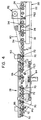
- the first sensor such as photoeye PE1 is placed at a predetermined position close to the front end of the assembly as shown in Figures 3 and 4.
- the second sensor such as photoeye PE2 is placed a predetermined distance from PE1 in the retracted position of the tread server assembly 28.
- the third sensor such as photoeye PE3 is positioned at a predetermined position under the upper frame structure 50.
- a conveyor encoder is connected to the drive assembly 82 for measuring and determining the distance the tread 35 is moved by rotation of the driven rollers 72.
- An encoder E2 is connected to a shaft 94 of the drum 18 to determine the rotation and wrapped circumference of the drum during wrapping of the tread 35 around the drum.
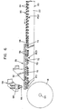
- the operation of the tread server 10 embodying the invention is shown diagrammatically in Figures 6 through 10.
- the tread server assembly 28 is moved by drive motor 42 from the retracted position shown in full lines to the extended position shown in dot dash lines in Figure 1 and in Figures 6 through 10.
- the tread 35 is conveyed to the assembly 28 on rollers 24 as shown in Fig 6.
- the leading edge 98 of the tread 35 is gripped by the rollers 72 at a position covering photoeye PE3 and pulled toward the drum 18 between the tilted guide rollers 86.
- the leading edge 98 passes over the photoeye PE1 the pricker bars 52 are moved downwardly into engagement with the leading edge as shown in Figure 7.
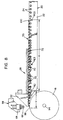
- the pricker bars 52 then move the tread 35 until a trailing edge 100 of the tread passes the photoeye PE2 as shown in Fig 8.
- the distance X between photoeye PE1 and photoeye PE2 is equivalent to n encoder counts and is known. This distance is added to the distance Y in encoder counts between the photoeye PE1 and the position of the pricker bars 52 in Fig 8 to determine the total initial length of the tread in encoder counts.
- the ratio of the initial length of the tread to the circumference of the drum 18 in encoder counts is then used to determine the ratio of the conveyor speed to the speed of rotation of the drum.
- the speed of rotation of the drum 18 is regulated so that it is greater than the conveyor speed.
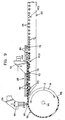
- a second measurement and adjustment of the tread application to the drum 18 is provided when the trailing edge 100 passes over the photoeye PE3 as shown in Fig 9.
- the conveyor traveled "n actual” encoder counts to move the trailing edge 100 from photoeye PE2 to photoeye PE3.
- the length between photoeye PE2 and PE3 is “n” counts. Accordingly when there is controlled stretching of the tread it is shown by the difference between "n” and "n actual.”
- the percent stretch n actual - n n x 100%
- the method includes a second step of calculating a second ratio between the drum encoder count for the length Z of the drum 18 not wrapped by the tread 35 as shown in Fig 9 and the conveyor encoder count for the distance between photoeye PE3 and the end of the conveyor 20.
- the trailing edge 100 is gripped by the pricker bars 52 which are carried by the pricker bar frame 46 to a position over photoeye PE3 as shown in Fig 9 and then to a position over the drum 18 where the trailing edge 100 is spliced to the leading edge 98 of the tread and pressed together at a splice 102 by a tack down roller 66 shown in Fig 10.
- the tread server assembly 28 may then be retracted and a transfer ring (not shown) of a tire building machine is utilized to transfer the belt and tread assembly to a tire carcass disposed on a tire shaping drum (not shown).
- a typical transfer apparatus is shown and described in US-A- 4 304 619 issued December 8, 1981.
- the resulting tire will have a tire carcass with a pair of spaced apart beads connected by reinforcing plies, a belt member extending circumferentially around the tire carcass and a tread member 35 wrapped around the belt member.
- a tire of this construction is shown and described in US-A-4 470 865 issued September 11, 1984.
Landscapes
- Engineering & Computer Science (AREA)
- Mechanical Engineering (AREA)
- Textile Engineering (AREA)
- Tyre Moulding (AREA)
- Testing Of Balance (AREA)
Description
- This invention relates to a tread server for applying a tire tread to a drum and splicing the tread accurately without the need of an operator. In addition, the tread is centered without distorting the edges.
- Heretofore, treads have been measured once and the drum speed of rotation varied to compensate for variations between the tread length and the circumference of the drum. There have not been additional measurements during the conveying process to compensate for changes in length during the guiding and conveying of the tread. There have also been no positive guiding and positioning of the leading end and trailing end to provide a precision splice of the tread on the drum. Guide rollers have been used to center the tread, however no provision has been made for preventing distortion of the edges of wide, thin treads or soft compound treads.
- The present invention provides for measuring the length of the tread while on the conveyor and before it is wrapped on the drum. Then the length is measured a second time after the tread is partially wrapped on the drum. Each time the ratio between the length of the tread and the circumference of the drum is obtained and the resulting ratio between the speed of rotation of the drum and the conveyor speed of the trailing edge of the tread is utilized to carry the trailing edge to a position on the drum where the leading edge is located for accurately splicing the ends of the tread. In this way the stretching of the tread is controlled. In fact, for certain tires the tread may be stretched different amounts where desired by utilizing the concept of this invention. In addition to controlling the stretching of the tread the ends are controlled by a pricker bar which carries the leading edge to a predetermined splice position on the drum and then is utilized to carry the trailing edge to the predetermined splice position.
- Guiding of the tread in accordance is provided by guide rolls tilted to engage the inner side edges of the tread shoulders to avoid distorting the tread side edges.
- In accordance with the invention, there is provided a an apparatus for wrapping and controlling the stretching of an extruded tread member of elastomeric material cut to an initial length around a belt member on a drum to provide for splicing a leading edge and a trailing edge of the tread member on the drum as defined in claim 1.
- In accordance with a further aspect of the invention, there is provided a method of stretching and applying a tire tread to a rotatable drum from a conveyor adjacent the drum as defined in claim 6.
- Preferred embodiments of the apparatus and of the method are recited in the dependent claims.
- To acquaint person skilled in the arts most closely related to the present invention certain preferred embodiments thereof illustrating the best made now contemplated for putting the invention into practice are described herein, by and with reference to the annexed drawings forming a part of the specification. The embodiments shown and described herein are illustrative.
-
- Figure 1 is a side elevation of the tread applier shown with the tread server in the retracted position;
- Figure 2 is a front elevation partially in section taken along the line 2-2 in Figure 1;
- Figure 3 is an enlarged plan view of the tread server shown in Figures 1 and 2;
- Figure 4 is a side sectional view of the tread server taken along line 4-4 in Figure 3;
- Figure 5 is a fragmentary view like Figure 2 of a modified guide roller arrangement;
- Figure 6 is a diagrammatic view like Figure 1 showing the tread server extended into position adjacent the drum and showing the tread just as it enters the position between the guide rollers;
- Figure 7 is a view like Figure 6 showing the tread with the leading edge at the first sensor and with the pricker bar gripper in engagement with the leading edge at the time the conveyor encoder is started to measure the length of the tread;
- Figure 8 is a view like Figure 7 showing the pricker bar advancing the leading edge of the tread to the drum and a first tread measurement being made;
- Figure 9 is a view like Figure 8 showing the tread partially wrapped around the drum and the pricker bar engaging the trailing edge of the tread with a second measurement of the length of the tread being made;
- Figure 10 is a view like Figure 8 showing the trailing edge advanced by the pricker bar to the drum and an automatic splice being made.
-
- A
tread server 10 embodying the invention is shown in Figures 1 and 2 and has aframe 12 withlegs 14 for supporting engagement with afloor 16 at a position adjacent a tire tread andbelt building drum 18. Theframe 12 supports atread conveyor 20 havingside beams 22 supportingtransverse rollers 24 at anentrance end 26 and atread server assembly 28 at anexit end 30. Aguide fence 32 havingvertical guide rollers 34 mounted on transversely adjustable fence bars is provided to guide atread 35 along theconveyor 20 which may be fed automatically or by hand into theentrance end 26 of the conveyor. - The
tread server assembly 28 has aframe 36 withside rails 38 supported on spaced apartside wheels 40 mounted on theframe 12. Suitable power means such as amotor 42 may be provided for moving thetread server assembly 28 from the retractable position shown in full lines in Figure 1 to the extended position shown in dot dash lines close to the belt andtread drum 18. - Mounted above the
tread server assembly 28 is apricker bar assembly 44 having apricker bar frame 46 supported onrails 48 on anupper frame structure 50.Pricker bars 52 are mounted on thebar frame 46 for movement vertically into engagement with thetread 35 by suitable lifting and lowering means 54. Horizontal movement of thepricker bar assembly 44 is also provided by suitable ball-screw andmotor assembly 56. - A tack down
roller assembly 58 is also slidably mounted on theupper frame structure 50. A rail 60 on theroller assembly 58 is slidably mounted in agroove 62 of a slider bar 63 carried by theframe structure 50. Suitable means for moving the tack downroller assembly 58 horizontally toward and away from thedrum 18 is provided such as piston cylinder assembly 64. A tack downroller 66 is mounted on a rollerpiston cylinder assembly 68 attached to the end of the tack downroller assembly 58 for moving the roller vertically into engagement with thetread 35. - Referring to Figures 3 and 4, enlarged views of the
tread server assembly 28 are shown incorporating a plurality of splined drivenshafts 70 in side by side relation withrollers 72 having grooved cylindrical holes for sliding on the shafts. Springs 74 are disposed at the ends of theshafts 70 in resilient engagement with theend rollers 72 to permit transverse movement of thetread 35 while at the same time driving the tread a predetermined distance. Each of theshafts 70 has asprocket 78 driven by achain 80 in driven relation with thedrive assembly 82. An encoder may be driven by thedrive assembly 82 to control the movement of thetread 35 through thetread server assembly 28. Acentering mechanism 84 has a pinion and rack assembly for urging tiltedguide rollers 86 into engagement withouter surface 88 of the raised shoulders of thetread 35. In a modification shown in Figure 5 spring loadedguide rollers 90 are positioned inward from the raised shoulders of thetread 35 and mounted for engagement withinner surfaces 92 of the raised shoulders of the tread. - In order to determine the length and position of the
tread 35 position, sensors such as photoeyes PE1, PE2 and PE3 are placed along the length of thetread server assembly 28. The first sensor such as photoeye PE1 is placed at a predetermined position close to the front end of the assembly as shown in Figures 3 and 4. The second sensor such as photoeye PE2 is placed a predetermined distance from PE1 in the retracted position of thetread server assembly 28. The third sensor such as photoeye PE3 is positioned at a predetermined position under theupper frame structure 50. A conveyor encoder is connected to thedrive assembly 82 for measuring and determining the distance thetread 35 is moved by rotation of the drivenrollers 72. An encoder E2 is connected to ashaft 94 of thedrum 18 to determine the rotation and wrapped circumference of the drum during wrapping of thetread 35 around the drum. - The operation of the
tread server 10 embodying the invention is shown diagrammatically in Figures 6 through 10. After the belts (not shown) are wrapped around thedrum 18 thetread server assembly 28 is moved bydrive motor 42 from the retracted position shown in full lines to the extended position shown in dot dash lines in Figure 1 and in Figures 6 through 10. Thetread 35 is conveyed to theassembly 28 onrollers 24 as shown in Fig 6. The leadingedge 98 of thetread 35 is gripped by therollers 72 at a position covering photoeye PE3 and pulled toward thedrum 18 between thetilted guide rollers 86. When the leadingedge 98 passes over the photoeye PE1 thepricker bars 52 are moved downwardly into engagement with the leading edge as shown in Figure 7. Thepricker bars 52 then move thetread 35 until atrailing edge 100 of the tread passes the photoeye PE2 as shown in Fig 8. The distance X between photoeye PE1 and photoeye PE2 is equivalent to n encoder counts and is known. This distance is added to the distance Y in encoder counts between the photoeye PE1 and the position of thepricker bars 52 in Fig 8 to determine the total initial length of the tread in encoder counts. The ratio of the initial length of the tread to the circumference of thedrum 18 in encoder counts is then used to determine the ratio of the conveyor speed to the speed of rotation of the drum. For example if the initial measured tread length is less than the circumference of thedrum 35 by more than the desired stretching of the tread by the drivenrollers 72 and tiltedguide rollers 86 the speed of rotation of thedrum 18 is regulated so that it is greater than the conveyor speed. - A second measurement and adjustment of the tread application to the
drum 18 is provided when the trailingedge 100 passes over the photoeye PE3 as shown in Fig 9. The conveyor traveled "n actual" encoder counts to move the trailingedge 100 from photoeye PE2 to photoeye PE3. The length between photoeye PE2 and PE3 is "n" counts. Accordingly when there is controlled stretching of the tread it is shown by the difference between "n" and "n actual." - With this information the initial ratio of conveyor speed to speed of rotation of the
drum 18 can be decreased by the percent stretch. The method includes a second step of calculating a second ratio between the drum encoder count for the length Z of thedrum 18 not wrapped by thetread 35 as shown in Fig 9 and the conveyor encoder count for the distance between photoeye PE3 and the end of theconveyor 20. The trailingedge 100 is gripped by the pricker bars 52 which are carried by thepricker bar frame 46 to a position over photoeye PE3 as shown in Fig 9 and then to a position over thedrum 18 where the trailingedge 100 is spliced to the leadingedge 98 of the tread and pressed together at asplice 102 by a tack downroller 66 shown in Fig 10. - The
tread server assembly 28 may then be retracted and a transfer ring (not shown) of a tire building machine is utilized to transfer the belt and tread assembly to a tire carcass disposed on a tire shaping drum (not shown). A typical transfer apparatus is shown and described in US-A- 4 304 619 issued December 8, 1981. - After the belt and tread assembly-is applied to the tire carcass the resulting tire will have a tire carcass with a pair of spaced apart beads connected by reinforcing plies, a belt member extending circumferentially around the tire carcass and a
tread member 35 wrapped around the belt member. A tire of this construction is shown and described in US-A-4 470 865 issued September 11, 1984. - While certain representative embodiments and details have been shown for the purpose of illustrating the invention, it will be apparent to those skilled in the art that various changes and modifications may be made therein without departing from the scope of the claims.
Claims (9)
- Apparatus for wrapping and controlling stretching of an extruded tread member (35) of elastomeric material cut to an initial length around a belt member on a drum (18) to provide for splicing a leading edge (98) and a trailing edge (100) of said tread member on said drum comprising:a. a generally horizontal conveyor (20) positioned with a discharge end (30) adjacent said drum (18);b. driving rollers (72) on said conveyor for carrying said tread member;c. a tread gripper (52) disposed above and movable along said conveyor for gripping said tread member;d. a first sensor (PE1) disposed adjacent a front end of said conveyor (20) for detecting said location of said leading edge of said tread member in a first position of said tread member;e. a second sensor (PE2) disposed adjacent said discharge end (26) of said conveyor for detecting said location of a trailing edge of said tread member in a second position of said tread member, characterized byf. a third sensor (PE3) disposed adjacent said conveyor between said first sensor and said second sensor for detecting said location of said trailing edge (100) of said tread member in a third position of said tread member;g. a conveyor encoder for measuring said distance said tread member and said gripper are moved on said conveyor;h. a drum encoder (E2) for measuring said distance said tread member is moved on said drum; andi. said sensors being operatively connected to said drum encoder and said conveyor encoder to control said relative speeds of said drum (18) and said conveyor in response to signals from said first sensor, said second sensor, said third sensor and by said conveyor encoder and drum encoder to provide for stretching said tread member and joining said leading edge and said trailing edge in a splice of said tire tread member at a predetermined position on said drum.
- Apparatus in accordance with claim 1 further characterized by said gripper (52) being moveable into engagement with said leading edge (98) of said tread member of said first sensor in said first position of said tread member and moveable with said tread member into said second position of said tread member.
- Apparatus in accordance with claim 1 further characterized by having a tack roll (66) adjacent said drum at said discharge end (30) of said conveyor (20) moveable into engagement with said leading edge (98) of said tread member for pressing said tread member against said drum (18).
- Apparatus in accordance with claim 1 further characterized by the driven rollers (72) on said conveyor (20) for supporting said tread, being moveable laterally to permit lateral guiding of said tread and guide rollers (86) at each side of said conveyor engageable with said tread to provide said lateral guiding.
- The apparatus of claim 4 further characterized by said tread having raised shoulders at each side and by guide rollers (90) positioned to engage said inner edges (92) of said shoulders and maintain a controlled guide pressure on said tread.
- A method of stretching and applying a tire tread (35) to a rotatable drum (18) from a conveyor (20) adjacent said drum characterized by the steps of:a. feeding said tire tread onto a conveyor until a leading edge (98) of said tire tread (35) is detected by a first sensor (PE1) at a first position of said tire tread.b. gripping said tire tread at said leading edge with a gripper (52) connected to a conveyor encoder;c. continuing to move said tread along said conveyor until a trailing edge (100) of said tire tread is detected by a second sensor (PE2) at a second position of said tire tread;d. calculating said length of said tire tread by adding said known distance (x) between said first sensor (PE1) and said second sensor (PE2) to said distance (y) moved by said gripper (52) as calculated by said conveyor encoder;e. calculating a first ratio between said circumference of said drum as measured by a drum encoder (E2) and said length of said tire tread as calculated by said conveyor encoder for determining said required speeds of said drum and conveyor to stretch and wrap said tire tread on said second drum;f. removing said gripper;g. applying a leading edge of said tire tread to said drum;h. rotating said drum and driving said conveyor at said required speeds until said trailing edge of said tire tread is detected by a third sensor (PE3) positioned adjacent said conveyor between said first sensor (PE1) and said second sensor (PE2) to measure said length of said tread in a third position,i. moving said gripper (52) to a position over said trailing edge and gripping said trailing edge (100);j. calculating a second ratio between said drum encoder count for said length (z) of said drum not wrapped by said tread and said conveyor encoder count for said distance between said third sensor and said end of said conveyor;k. rotating said drum while operating said conveyor and moving said gripper (52) at different speeds determined in accordance with said second ratio to stretch said tire tread so that said leading edge (98) and said trailing (100) edge will be joined on said drum (18) for splicing and;l. removing said gripper (52) from said trailing edge after splicing.
- The method of claim 6 further characterized by moving said tread (35) along said conveyor (20) adjacent said drum, on laterally moveable driven rollers; and, by engaging inner edges of raised shoulders of said tread with guide rollers (90) to center said tread.
- The method of claim 7 further characterized by said guide rollers (90) exerting centering pressure on said shoulders toward said outer edges of said tread.
- The method of claim 8 further characterized by said centering pressure by said guide rollers (90) being applied after said tread is moved into said space between said guide rollers.
Applications Claiming Priority (2)
| Application Number | Priority Date | Filing Date | Title |
|---|---|---|---|
| US56336395A | 1995-11-28 | 1995-11-28 | |
| US563363 | 1995-11-28 |
Publications (3)
| Publication Number | Publication Date |
|---|---|
| EP0776757A2 EP0776757A2 (en) | 1997-06-04 |
| EP0776757A3 EP0776757A3 (en) | 1998-02-04 |
| EP0776757B1 true EP0776757B1 (en) | 2002-01-23 |
Family
ID=24250211
Family Applications (1)
| Application Number | Title | Priority Date | Filing Date |
|---|---|---|---|
| EP96117969A Expired - Lifetime EP0776757B1 (en) | 1995-11-28 | 1996-11-08 | Tyre tread server and method of applying a tyre tread |
Country Status (12)
| Country | Link |
|---|---|
| US (1) | US5882457A (en) |
| EP (1) | EP0776757B1 (en) |
| JP (1) | JPH09174715A (en) |
| KR (1) | KR970025931A (en) |
| CN (1) | CN1064591C (en) |
| AU (1) | AU717929B2 (en) |
| BR (1) | BR9605594A (en) |
| CA (1) | CA2180767A1 (en) |
| DE (1) | DE69618750T2 (en) |
| ES (1) | ES2171593T3 (en) |
| MX (1) | MX9605639A (en) |
| PL (1) | PL317249A1 (en) |
Cited By (2)
| Publication number | Priority date | Publication date | Assignee | Title |
|---|---|---|---|---|
| DE102006017882A1 (en) * | 2006-04-13 | 2007-10-18 | Texmag Gmbh Vertriebsgesellschaft | Device and method for building a tire |
| TWI764806B (en) * | 2021-08-12 | 2022-05-11 | 大陸商常州欣盛半導體技術股份有限公司 | High precision film feeding device |
Families Citing this family (30)
| Publication number | Priority date | Publication date | Assignee | Title |
|---|---|---|---|---|
| KR100626560B1 (en) * | 1999-02-23 | 2006-09-22 | 요코하마 고무 가부시키가이샤 | Pneumatic tire and process for fabricating the same |
| JP4493163B2 (en) * | 1999-06-25 | 2010-06-30 | 株式会社ブリヂストン | Joining system for sheet-like unvulcanized rubber materials |
| EP1120233A3 (en) * | 2000-01-27 | 2001-10-24 | Bandag Incorporated | Method and apparatus for retreading tires |
| US6899778B1 (en) * | 2000-01-27 | 2005-05-31 | Bandag Incorporated | Method and apparatus for preparing tire tread for a retread tire |
| EP1120234A3 (en) * | 2000-01-27 | 2001-10-24 | Bandag Incorporated | Method and apparatus for applying cushion gum on a tire casing |
| US6758931B1 (en) * | 2000-01-27 | 2004-07-06 | Bandag, Incorporated | Method and apparatus for applying tire tread for a retread tire |
| US6773530B2 (en) | 2001-09-21 | 2004-08-10 | The Goodyear Tire & Rubber Company | Method for manufacturing tires on a flexible manufacturing system |
| US6790301B2 (en) * | 2001-10-15 | 2004-09-14 | The Goodyear Tire And Rubber Company | Method and apparatus for making a tread-belt assembly |
| KR100451969B1 (en) * | 2002-01-14 | 2004-10-08 | 금호타이어 주식회사 | Component centering unit for tire building machine |
| JP4133301B2 (en) * | 2002-12-25 | 2008-08-13 | 株式会社ブリヂストン | Manufacturing method of tire component |
| US8236228B2 (en) * | 2005-07-28 | 2012-08-07 | Michelin Recherche Et Technique | Apparatus and method for loading a tread press |
| DE102005041564A1 (en) * | 2005-09-01 | 2007-03-08 | Continental Aktiengesellschaft | Apparatus for winding a strip-shaped rubber material |
| DE102005041565A1 (en) * | 2005-09-01 | 2007-03-08 | Continental Aktiengesellschaft | Apparatus for winding a strip-shaped rubber material |
| FR2908070A1 (en) * | 2006-11-02 | 2008-05-09 | Michelin Soc Tech | METHOD FOR DETERMINING THE OPERATING PARAMETERS OF A DEVICE FOR THE INSTALLATION OF A THREAD BY PROJECTION |
| CN101850628B (en) * | 2009-04-01 | 2012-10-10 | 软控股份有限公司 | Shoulder wedge feeding frame and front guiding and positioning method thereof |
| CN101966756B (en) * | 2009-07-27 | 2013-06-05 | 软控股份有限公司 | Full automatic tread abutting machine and abutting method thereof |
| FR2954727B1 (en) * | 2009-12-24 | 2012-04-13 | Michelin Soc Tech | METHOD AND DEVICE FOR MEASURING THE FRONT PANEL ANGLE |
| CN101905540B (en) * | 2010-07-12 | 2012-12-19 | 天津赛象科技股份有限公司 | Belted layer feed rack of giant embryo shaping machine |
| MX348342B (en) * | 2011-12-22 | 2017-06-06 | Pirelli | Process and apparatus for building tyres for vehicle wheels. |
| NL2009769C2 (en) * | 2012-11-07 | 2014-05-08 | Vmi Holland Bv | Tyre layer application assembly. |
| NL2009946C2 (en) * | 2012-12-10 | 2014-06-11 | Vmi Holland Bv | Tyre building machine for forming a bead-apex assembly. |
| NL2011308C2 (en) * | 2013-08-15 | 2015-02-19 | Vmi Holland Bv | Belt and tread drum. |
| NL2014365B1 (en) * | 2015-02-27 | 2016-10-13 | Vmi Holland Bv | Conveyor and method for conveying a tire component. |
| US11691367B2 (en) | 2015-12-17 | 2023-07-04 | Pirelli Tyre S.P.A. | Method and apparatus for handling tyres |
| FR3051388A1 (en) * | 2016-05-18 | 2017-11-24 | Michelin & Cie | |
| FR3065897A1 (en) * | 2017-05-05 | 2018-11-09 | Compagnie Generale Des Etablissements Michelin | AUTOMATED DEVICE FOR GRIPPING AND HANDLING A BEARING BAND FOR A TIRE. |
| NL2018959B1 (en) * | 2017-05-22 | 2018-12-04 | Vmi Holland Bv | Method and assembly for applying a tire component to a drum |
| EP3760354A1 (en) * | 2019-07-03 | 2021-01-06 | Hilti Aktiengesellschaft | Ring saw |
| US20240140059A1 (en) * | 2022-10-31 | 2024-05-02 | The Goodyear Tire & Rubber Company | Tire building machine |
| CN116278102A (en) * | 2023-03-06 | 2023-06-23 | 杭州海潮橡胶有限公司 | Tire tread conveying and attaching equipment of tire building machine |
Family Cites Families (21)
| Publication number | Priority date | Publication date | Assignee | Title |
|---|---|---|---|---|
| US1419064A (en) * | 1919-08-11 | 1922-06-06 | Goodyear Tire & Rubber | Tire-making machine |
| US2346439A (en) * | 1941-07-12 | 1944-04-11 | Goodrich Co B F | Tire-building apparatus |
| US3052395A (en) * | 1960-04-21 | 1962-09-04 | Perkin Elmer Corp | Rollers |
| US3139963A (en) * | 1961-01-04 | 1964-07-07 | Continental Gummi Werke Ag | Roller guide |
| US3393112A (en) * | 1964-01-17 | 1968-07-16 | Uniroyal Inc | Tire building apparatus and method |
| US3847705A (en) * | 1973-01-22 | 1974-11-12 | Uniroyal Inc | Apparatus for conveying a tire tread |
| US4049486A (en) * | 1975-10-15 | 1977-09-20 | The General Tire & Rubber Company | Rubber strip guide apparatus |
| SU880783A2 (en) * | 1979-05-24 | 1981-11-15 | Ярославский политехнический институт | Method of feeding tread works to assembly drum of machine for assembling covers of pneumatic tyres |
| US4304619A (en) | 1980-01-14 | 1981-12-08 | The Goodyear Tire & Rubber Company | Method and apparatus for off-loading a completed uncured tire |
| US4874443A (en) * | 1982-09-27 | 1989-10-17 | The Firestone Tire & Rubber Company | Method for applying elastomeric material onto a drum |
| US4470865A (en) | 1982-12-16 | 1984-09-11 | The Goodyear Tire & Rubber Company | Tire tread belt and method of making |
| DE3421831A1 (en) * | 1984-06-13 | 1985-12-19 | Fried. Krupp Gmbh, 4300 Essen | METHOD FOR BUILDING TIRE BLANKS |
| JPH0745208B2 (en) * | 1986-04-07 | 1995-05-17 | 株式会社ブリヂストン | Method and apparatus for forming cylindrical tire constituent member |
| JPH0813515B2 (en) * | 1987-07-09 | 1996-02-14 | 株式会社ブリヂストン | Band-shaped end clamping device |
| US5194107A (en) * | 1987-09-03 | 1993-03-16 | Bridgestone Corporation | Belt-like member attaching method and apparatus |
| US5292398A (en) * | 1989-11-13 | 1994-03-08 | Mitsubishi Jukogyo Kabushiki Kaisha | Apparatus for joining a tread in a machine for making a tire |
| DE4108515A1 (en) * | 1990-03-17 | 1991-09-19 | Toyo Tire & Rubber Co | Process for winding strip on to tyre building drum - detects ends of strip and has automatic control circuitry to ensure that they meet precisely on the drum without overlap or gap |
| JP3179131B2 (en) * | 1991-05-24 | 2001-06-25 | 株式会社ブリヂストン | Method and apparatus for attaching band member |
| FR2677300A1 (en) * | 1991-06-05 | 1992-12-11 | Laurent Pneu | DEVICE FOR MEASURING THE RUNNING OF A TREAD BELT DURING ITS APPLICATION ON A TIRE CARCASS AND ITS IMPLEMENTING METHOD. |
| US5389187A (en) * | 1993-06-30 | 1995-02-14 | The Goodyear Tire & Rubber Company | Apparatus for tire tread application |
| DE4407964A1 (en) * | 1994-03-10 | 1995-09-14 | Continental Ag | Method and device for the automatic placement and splicing of material webs on a tire building drum |
-
1996
- 1996-07-09 CA CA002180767A patent/CA2180767A1/en not_active Abandoned
- 1996-11-08 ES ES96117969T patent/ES2171593T3/en not_active Expired - Lifetime
- 1996-11-08 EP EP96117969A patent/EP0776757B1/en not_active Expired - Lifetime
- 1996-11-08 DE DE69618750T patent/DE69618750T2/en not_active Expired - Fee Related
- 1996-11-18 BR BR9605594-4A patent/BR9605594A/en not_active IP Right Cessation
- 1996-11-18 MX MX9605639A patent/MX9605639A/en unknown
- 1996-11-27 KR KR1019960058439A patent/KR970025931A/en not_active Ceased
- 1996-11-27 AU AU74032/96A patent/AU717929B2/en not_active Ceased
- 1996-11-28 JP JP8317520A patent/JPH09174715A/en active Pending
- 1996-11-28 PL PL96317249A patent/PL317249A1/en unknown
- 1996-11-28 CN CN96117251A patent/CN1064591C/en not_active Expired - Fee Related
-
1997
- 1997-04-23 US US08/847,322 patent/US5882457A/en not_active Expired - Fee Related
Cited By (3)
| Publication number | Priority date | Publication date | Assignee | Title |
|---|---|---|---|---|
| DE102006017882A1 (en) * | 2006-04-13 | 2007-10-18 | Texmag Gmbh Vertriebsgesellschaft | Device and method for building a tire |
| DE102006017882B4 (en) * | 2006-04-13 | 2010-08-05 | Texmag Gmbh Vertriebsgesellschaft | Device and method for building a tire |
| TWI764806B (en) * | 2021-08-12 | 2022-05-11 | 大陸商常州欣盛半導體技術股份有限公司 | High precision film feeding device |
Also Published As
| Publication number | Publication date |
|---|---|
| PL317249A1 (en) | 1997-06-09 |
| CA2180767A1 (en) | 1997-05-29 |
| MX9605639A (en) | 1998-04-30 |
| DE69618750T2 (en) | 2002-08-14 |
| BR9605594A (en) | 1999-12-21 |
| CN1064591C (en) | 2001-04-18 |
| AU717929B2 (en) | 2000-04-06 |
| EP0776757A2 (en) | 1997-06-04 |
| ES2171593T3 (en) | 2002-09-16 |
| JPH09174715A (en) | 1997-07-08 |
| EP0776757A3 (en) | 1998-02-04 |
| CN1156665A (en) | 1997-08-13 |
| US5882457A (en) | 1999-03-16 |
| KR970025931A (en) | 1997-06-24 |
| AU7403296A (en) | 1997-06-05 |
| DE69618750D1 (en) | 2002-03-14 |
Similar Documents
| Publication | Publication Date | Title |
|---|---|---|
| US5882457A (en) | Tire tread guiding | |
| MXPA96005639A (en) | Rim band bearing server and met | |
| GB2153760A (en) | Feeding strip material in the manufacture of pneumatic tyres | |
| US5175930A (en) | Method and apparatus for attaching belt-shaped member to forming drum | |
| JPS6132980B2 (en) | ||
| US20090126874A1 (en) | Supply device for a tire-building drum | |
| US5194107A (en) | Belt-like member attaching method and apparatus | |
| US4824001A (en) | Method for centering materials | |
| CN103619572A (en) | Process and apparatus for building tyres for vehicle wheels | |
| US4874443A (en) | Method for applying elastomeric material onto a drum | |
| JPH04347630A (en) | Method and device for sticking beltlike member | |
| CA1211353A (en) | Innerliner applicator | |
| RU2676284C1 (en) | Method and apparatus for applying band-like elastomeric element for tyres on forming support in process for building tyre for vehicle wheels | |
| EP0109475B1 (en) | Length correcting device for rubber strips in the building of tyres | |
| US4004958A (en) | Method and apparatus for producing better balanced tread components in pneumatic tires | |
| JPH0584849A (en) | Automatic feeding and pasting method for band-shaped materials | |
| US4361454A (en) | Ply applying apparatus and method for forming an elastic annular body | |
| US3676259A (en) | Tire building apparatus having a plurality of component applying stations and drums | |
| JPH05245952A (en) | Method and apparatus for winding striplike member | |
| US4749424A (en) | Methods and apparatus for the manufacture of pneumatic tires | |
| JP4605556B2 (en) | Retrending method | |
| JPH0531459B2 (en) | ||
| US3970261A (en) | Handling tire making materials | |
| JPH0531458B2 (en) | ||
| JPH0361031A (en) | Method and apparatus for supplying tire constitutional material |
Legal Events
| Date | Code | Title | Description |
|---|---|---|---|
| PUAI | Public reference made under article 153(3) epc to a published international application that has entered the european phase |
Free format text: ORIGINAL CODE: 0009012 |
|
| 17P | Request for examination filed |
Effective date: 19961108 |
|
| AK | Designated contracting states |
Kind code of ref document: A2 Designated state(s): DE ES FR GB IT NL |
|
| PUAL | Search report despatched |
Free format text: ORIGINAL CODE: 0009013 |
|
| AK | Designated contracting states |
Kind code of ref document: A3 Designated state(s): DE ES FR GB IT NL |
|
| 17Q | First examination report despatched |
Effective date: 20000202 |
|
| GRAG | Despatch of communication of intention to grant |
Free format text: ORIGINAL CODE: EPIDOS AGRA |
|
| GRAG | Despatch of communication of intention to grant |
Free format text: ORIGINAL CODE: EPIDOS AGRA |
|
| GRAH | Despatch of communication of intention to grant a patent |
Free format text: ORIGINAL CODE: EPIDOS IGRA |
|
| GRAH | Despatch of communication of intention to grant a patent |
Free format text: ORIGINAL CODE: EPIDOS IGRA |
|
| GRAA | (expected) grant |
Free format text: ORIGINAL CODE: 0009210 |
|
| REG | Reference to a national code |
Ref country code: GB Ref legal event code: IF02 |
|
| AK | Designated contracting states |
Kind code of ref document: B1 Designated state(s): DE ES FR GB IT NL |
|
| PG25 | Lapsed in a contracting state [announced via postgrant information from national office to epo] |
Ref country code: NL Free format text: LAPSE BECAUSE OF FAILURE TO SUBMIT A TRANSLATION OF THE DESCRIPTION OR TO PAY THE FEE WITHIN THE PRESCRIBED TIME-LIMIT Effective date: 20020123 |
|
| REF | Corresponds to: |
Ref document number: 69618750 Country of ref document: DE Date of ref document: 20020314 |
|
| ET | Fr: translation filed | ||
| NLV1 | Nl: lapsed or annulled due to failure to fulfill the requirements of art. 29p and 29m of the patents act | ||
| REG | Reference to a national code |
Ref country code: ES Ref legal event code: FG2A Ref document number: 2171593 Country of ref document: ES Kind code of ref document: T3 |
|
| PG25 | Lapsed in a contracting state [announced via postgrant information from national office to epo] |
Ref country code: GB Free format text: LAPSE BECAUSE OF NON-PAYMENT OF DUE FEES Effective date: 20021108 |
|
| PG25 | Lapsed in a contracting state [announced via postgrant information from national office to epo] |
Ref country code: ES Free format text: LAPSE BECAUSE OF NON-PAYMENT OF DUE FEES Effective date: 20021109 |
|
| PLBE | No opposition filed within time limit |
Free format text: ORIGINAL CODE: 0009261 |
|
| STAA | Information on the status of an ep patent application or granted ep patent |
Free format text: STATUS: NO OPPOSITION FILED WITHIN TIME LIMIT |
|
| 26N | No opposition filed | ||
| PG25 | Lapsed in a contracting state [announced via postgrant information from national office to epo] |
Ref country code: DE Free format text: LAPSE BECAUSE OF NON-PAYMENT OF DUE FEES Effective date: 20030603 |
|
| GBPC | Gb: european patent ceased through non-payment of renewal fee | ||
| PG25 | Lapsed in a contracting state [announced via postgrant information from national office to epo] |
Ref country code: FR Free format text: LAPSE BECAUSE OF NON-PAYMENT OF DUE FEES Effective date: 20030731 |
|
| REG | Reference to a national code |
Ref country code: FR Ref legal event code: ST |
|
| REG | Reference to a national code |
Ref country code: ES Ref legal event code: FD2A Effective date: 20031213 |
|
| PG25 | Lapsed in a contracting state [announced via postgrant information from national office to epo] |
Ref country code: IT Free format text: LAPSE BECAUSE OF NON-PAYMENT OF DUE FEES;WARNING: LAPSES OF ITALIAN PATENTS WITH EFFECTIVE DATE BEFORE 2007 MAY HAVE OCCURRED AT ANY TIME BEFORE 2007. THE CORRECT EFFECTIVE DATE MAY BE DIFFERENT FROM THE ONE RECORDED. Effective date: 20051108 |