EP0776101A2 - Method and apparatus for bidirectional high bit-rate digital data transmission using space diversity - Google Patents
Method and apparatus for bidirectional high bit-rate digital data transmission using space diversity Download PDFInfo
- Publication number
- EP0776101A2 EP0776101A2 EP96107315A EP96107315A EP0776101A2 EP 0776101 A2 EP0776101 A2 EP 0776101A2 EP 96107315 A EP96107315 A EP 96107315A EP 96107315 A EP96107315 A EP 96107315A EP 0776101 A2 EP0776101 A2 EP 0776101A2
- Authority
- EP
- European Patent Office
- Prior art keywords
- signal
- base station
- radio channel
- diversity
- transfer function
- Prior art date
- Legal status (The legal status is an assumption and is not a legal conclusion. Google has not performed a legal analysis and makes no representation as to the accuracy of the status listed.)
- Withdrawn
Links
Images


Classifications
-
- H—ELECTRICITY
- H04—ELECTRIC COMMUNICATION TECHNIQUE
- H04B—TRANSMISSION
- H04B7/00—Radio transmission systems, i.e. using radiation field
- H04B7/02—Diversity systems; Multi-antenna system, i.e. transmission or reception using multiple antennas
- H04B7/04—Diversity systems; Multi-antenna system, i.e. transmission or reception using multiple antennas using two or more spaced independent antennas
- H04B7/06—Diversity systems; Multi-antenna system, i.e. transmission or reception using multiple antennas using two or more spaced independent antennas at the transmitting station
- H04B7/0613—Diversity systems; Multi-antenna system, i.e. transmission or reception using multiple antennas using two or more spaced independent antennas at the transmitting station using simultaneous transmission
-
- H—ELECTRICITY
- H04—ELECTRIC COMMUNICATION TECHNIQUE
- H04B—TRANSMISSION
- H04B7/00—Radio transmission systems, i.e. using radiation field
- H04B7/02—Diversity systems; Multi-antenna system, i.e. transmission or reception using multiple antennas
- H04B7/04—Diversity systems; Multi-antenna system, i.e. transmission or reception using multiple antennas using two or more spaced independent antennas
- H04B7/08—Diversity systems; Multi-antenna system, i.e. transmission or reception using multiple antennas using two or more spaced independent antennas at the receiving station
- H04B7/0837—Diversity systems; Multi-antenna system, i.e. transmission or reception using multiple antennas using two or more spaced independent antennas at the receiving station using pre-detection combining
- H04B7/0842—Weighted combining
- H04B7/0845—Weighted combining per branch equalization, e.g. by an FIR-filter or RAKE receiver per antenna branch
Definitions
- the invention relates to a method for the bidirectional transmission of high-rate digital signals between at least one base station and at least one customer device via a radio link according to claim 1, a base station described in claim 9 for a digital radio network for carrying out the method and a digital radio network defined in claim 20 for execution of the procedure.
- the difficulty lies in finding transmission methods and transmission systems that can minimize the impairment of the digital signal transmission caused by the properties of the radio channel with the least possible effort and at the same time achieve a high bandwidth efficiency.
- the previously known methods for transmitting digital signals at high data rates can basically be divided into single-carrier methods and multi-carrier methods.
- the data stream is modulated onto a high-frequency carrier using a suitable modulation method, such as, for example, the Gaussian Minimum Shift Keying method, coded and transmitted in a suitable manner.
- a suitable modulation method such as, for example, the Gaussian Minimum Shift Keying method
- the signals emitted by a transmitting station are reflected on numerous objects located in the radio field and therefore spread over several radio paths to the receiving station.
- intersymbol interference occurs at the same time, which must be compensated for in the receiver by equalizing the signal.
- Viterbi equalizers based on the maximum likelihood sequence estimation approach are used, for example, or equalizers with a quantized feedback.
- digital signals with high data rates have correspondingly short symbol durations, which can result in inter-symbol interference over a large number of symbols, which cannot be eliminated with conventional Viterbi equalizers or equalizers with quantized feedback.
- the development of powerful time-domain equalizers that could solve this task is currently failing due to excessive hardware requirements.
- frequency domain equalizers require higher circuit complexity in the receivers of both the base station and the customer facilities, since each receiver must perform a transformation in the frequency domain and, after equalization in the frequency domain, must transform back into the time domain. This is particularly disadvantageous from the point of view that the customer facilities should be as simple and inexpensive as possible.
- the invention is therefore based on the object of providing a method for the bidirectional transmission of high-rate digital signals via a radio link, a base station for a digital radio network for carrying out the method and a digital radio network, which use the advantages of the known methods and at the same time reduce or even completely avoid their disadvantages.
- the solution according to the invention consists in particular in that a single-carrier method is used and the radio-specific signal processing is carried out in the receiver of a base station in the frequency domain.
- the digital signal emitted by a stationary or mobile customer device and propagating over several radio channels due to reflections from objects is received at at least two spatially separated diversity antennas of a receiving device of the base station. This reception is also known as diversity reception.
- Each diversity antenna is part of a separate diversity branch.
- the received signal of each diversity branch is converted to the baseband. Then it is transformed into the frequency domain and then subjected to a diversity combination.
- the diversity combination can be carried out on the basis of the known maximum ratio combining (MRC) approach or on the basis of a selection combining approach.
- MRC maximum ratio combining
- the combined signal is then equalized in the frequency domain and finally transformed back into the time domain.
- the digital signal transformed back into the time domain is fed to a demodulator known per se, which recovers the useful data from the complex baseband signal. Thanks to the joint implementation of a diversity combination and an equalization of the combined signal in the frequency domain, a significantly better bit error behavior is achieved than this would be possible with a frequency domain equalizer without a diversity combination. This is due to the fact that the frequency-selective properties are decorrelated for each diversity branch or radio channel over which the transmitted digital signal propagates. At those points where the transmission function of one radio channel has low amplitude drops, the other radio channel is very likely to have high amplitudes. Thus, the resulting transfer function after a diversity combination shows significantly smaller amplitude fluctuations than the respective transfer function of the two individual radio channels or diversity branches.
- the associated transfer function must be determined for each radio channel over which the digital signal propagates due to reflections from objects.
- reference symbols which have been previously agreed between the customer device and the base station are first sent out by the customer device, which wants to exchange data with a base station, at predetermined time intervals.
- the receiving device in the base station is designed in such a way that it can calculate the transfer function and the associated conjugate complex transfer function for each radio channel from the reference symbols.
- the resulting radio channel transmission function is calculated in the receiving device.
- the diversity combination is preferably carried out on the basis of the so-called maximum ratio combining approach, in which the frequency spectrum of each received signal is multiplied by the complex conjugate radio channel transmission function of the corresponding radio channel. Then all the spectral components of the received signals of each diversity branch weighted in this way are added.
- the combined signal will then equalized in the frequency domain by dividing the combination signal with the resulting radio channel transmission function previously calculated in the receiving device.
- the signal equalized in this way is then subjected to a time domain transformation and passed on to the demodulator.
- the high-rate digital signal to be transmitted from the base station to the customer device (this transmission direction is also referred to as the downlink or downward direction) is transformed into the frequency range in the base station and is applied to at least two branches connected in parallel.
- the signal applied to each branch is pre-distorted in the frequency domain and then transformed back into the time domain.
- the signal of each branch transformed back into the time domain is emitted after conversion into the high-frequency position via an antenna assigned to each branch, so that an undistorted signal is received at the receiving device of the customer device Signal is present. Thanks to this predistortion of the signal to be transmitted in the frequency range in the base station, the receiving device of each customer device can be manufactured with less complexity and therefore more cost-effectively.
- a transmission quality is achieved which only depends on the signal-to-noise ratio of the receiver of the customer device and no longer on the frequency-selective channel properties.
- the radiation of predistorted digital signals via at least two antennas, even with frequency-selective radio channels, only requires the same average transmission power as with an undistorted radio channel, without a deterioration in the bit error behavior occurring at the receiving device of the customer device. If, on the other hand, the digital signal were only to be emitted via an antenna of the base station, a much larger average transmission power would have to be used with a frequency-selective channel than with an undistorted transmission channel.
- the same average transmission power as in the undistorted case can be maintained even in the case of frequency-selective channels, despite predistortion, without a deterioration in the bit error behavior occurring at the receiving device of the customer device.
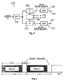
- FIG. 1 shows the block diagram of a bidirectional radio connection between a base station 10 and a customer device 20.
- the base station 10 shown in FIG. 1 and the customer device 20 can be part of a digital radio network, which can have a plurality of mobile or stationary base stations and a plurality of stationary and / or mobile customer devices.
- the base station 10 comprises, for example, two antennas 30 and 40, which are used both for receiving a digital signal from the customer device 20 (this transmission direction is also called uplink or upward direction) and for transmitting a digital signal from the base station 10 Customer device 20 (this direction of transmission is also called downlink or downward direction) can be used.
- known transceiver switches are provided which, depending on the operating mode, switch the antennas 30 and 40 into the transmitting or receiving mode.
- the antenna 30 forms the input of a first diversity branch 50
- the antenna 40 forms the input of a second diversity branch 55.
- the two diversity branches 50, 55 are in turn connected to the inputs of a signal processing device 60 which, according to the invention, carries out a diversity combination in the frequency range with the received signal of each diversity branch 50, 55, then equalizes the combined signal in the frequency range and transforms it back into the time range .
- a signal processing device 60 which, according to the invention, carries out a diversity combination in the frequency range with the received signal of each diversity branch 50, 55, then equalizes the combined signal in the frequency range and transforms it back into the time range .
- a possible circuit design and the mode of operation of the signal processing device 60 are described in detail below in connection with FIG. 2.
- the output of the signal processing device 60 is applied to a demodulator 70 which is known per se and which recovers the digital useful data from the complex baseband signal.
- the two antennas 30 and 40 working in the receive mode, the two diversity branches 50 and 55, the signal processing device 60 and the demodulator 70 together form a diversity receiver 80.
- the base station 10 also contains a transmission device 90, which in the present example also includes the two antennas 30 and 40 operating in the transmission mode.
- the transmitter 90 also includes a modulator 100 known per se, which generates the complex baseband signal from the digital useful data.
- the modulator 100 is connected to a signal processing device 110 which, according to the invention, divides the signal to be transmitted into two branches 120, 125 divides, predistorted in the frequency domain and feeds the two antennas 30 and 40.
- the transmission device 90 also has a digital-to-analog converter and a device for converting the transmission signal into the high-frequency range (not shown).
- a possible implementation of the signal conditioning device 110 in terms of circuitry and the method carried out by it are explained in more detail below in connection with FIG. 3.
- a control device 130 in the base station 10 ensures, on the one hand, that the antennas 30 and 40 are switched back and forth in the transmission or reception mode and that the signal conditioning device 110 and the signal processing device 60 are functionally controlled.
- the customer device 20 comprises, for example, a transceiver antenna 130 which is connected to a demodulator 140 known per se in the receive mode and to a modulator 150 known per se in the transmit mode.
- a generator device 160 serves to generate agreed reference symbols between the customer device 20 and the base station 10, which are sent to the base station at predetermined time intervals. The task of the reference symbols is described in detail below.
- a control device 170 ensures, on the one hand, that the transmission / reception antenna 130 is switched correctly to the transmission or reception mode and, on the other hand, to activate the generator device 160 whenever reference symbols are to be generated and transmitted to the base station 10.
- bit error rates BER Bit Error Rate
- AWGN Additive White Gaussian Noise
- Curve b) shows the behavior for a non-frequency-selective Rayleigh channel when it is received at base station 10 with only one antenna. This behavior occurs in multi-carrier methods in both frequency-selective and frequency-selective fading channels. Based on a bit error rate of 10 -4 , there is a deterioration of about 22 dB compared to the AWGN channel.
- Curve c) shows the result when using two diversity antennas under the same channel conditions as curve b). The combination of decorrelated fading processes leads to a significant improvement compared to curve b) (approx.
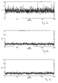
- FIGS. 4a to 4c The advantageous behavior of a diversity combination based on a maximum ratio combining approach can best be understood from FIGS. 4a to 4c.
- 4a is the amount for a transfer function of radio channel 1 and in FIG. 4b is the amount of a transfer function for radio channel 2 shown.
- the pattern functions shown in FIGS. 4a and 4b were generated with the aid of a "Typical Urban" synthetic channel model in accordance with the definitions of COST 207.
- 4c shows the resulting radio channel transfer function after the diversity combination according to the invention. While the transmission functions of the two radio channels 1 and 2 shown in FIGS. 4a and 4b have amplitude drops of up to 30 dB, the combined transfer function according to FIG. 4c only shows drops of the order of 10 dB.
- FIG. 3 shows the signal processing device 110 of the base station 10 in more detail.
- the signal processing device 110 shown in FIG. 3 is part of the transmission device 90.
- the modulated, high-frequency carrier signal coming from the modulator 100 is fed to a device 270 which transforms the time signal into the frequency range with the aid of a discrete Fourier transformation.
- the device 270 is referred to as a DFT device.
- the output of the DFT device 270 is connected to a first input of a multiplier 300 connected to branch 120 and to a first input of a second multiplier 320 connected to branch 125.
- the multiplier 300 is connected on the output side to an IDFT device 310, whereas the output of the multiplier 320 is present at the input of an IDFT device 330.
- Each IDFT device 310 and 330 carries out an inverse discrete Fourier transformation into the time domain with the transmission signal of each branch 120 or 125.
- the IDFT devices 310 and 330 can each be connected to the antenna 30 or 40 via a digital-to-analog converter and a high-frequency converter.
- a radio channel estimator 340 is configured similarly to the radio channel estimator 240 that is in the signal processing device 60 is used. An output of the radio channel estimator 340 is connected to the multiplier 300 and 320, respectively.
- the radio channel estimator 340 is therefore also able to determine the transmission functions and the associated conjugate complex transmission functions of the two radio channels 1 and 2 and the resulting radio channel transmission function. However, the radio channel estimator 340 also requires the reference symbols sent by the customer device 20.
- the time between the determination of the radio channel transmission functions and the signal transmission in downlink operation must be significantly shorter than the coherence time of radio channels 1 and 2. It is conceivable that switches 205 and 207 can be switched to a third position , so that the reference symbols can be transmitted via the DFT devices 200 and 210 to the estimating device 340. A further possibility is that the radio channel estimation device 240 of the receiving device 80 can completely take over the tasks of the radio channel estimation device 340 of the transmitting device 90 and can thus replace them. However, this is only possible if the downlink transmission of a digital signal in time duplex takes place on the same frequency as the uplink transmission. This technique is also known as time division duplex (TDD).
- TDD time division duplex
- the digital signal to be transmitted by the base station 10 is predistorted in the frequency domain by the signal processing device 110 in such a way that the signal emitted by the two antennas 30 and 40 can be received almost undistorted by the receiving antenna 130 of the customer device 20.
- the signal coming from the modulator 90 and transformed into the frequency range by the DFT device 270 is placed on the branch 120, multiplied by the conjugate complex transfer function of the radio channel 1 in the multiplier 300 and by dividing the resulting transfer function.
- the spectrum predistorted in this way passes through the IDFT device 310.
- a time signal is present at the output of the IDFT device 310, which is transmitted via the antenna 30 operating in transmission mode and via the distorted radio channel 1 to the receiving antenna 130.
- Customer setup and 20 is transferred.
- the frequency-transformed signal applied to branch 125 is multiplied by the conjugate complex transfer function of radio channel 2 in multiplier 320 and divided by the resulting transfer function.
- the signal predistorted in the frequency range then passes through the IDFT device 330.
- the time signal present at the output of the IDFT device 330 is then transmitted to the receiving antenna 130 via the antenna 40 and the distorted radio channel 2.
- the total of the predistorted signals transmitted via the distorted radio channels 1 and 2 can be received almost undistorted by the receiving antenna 130 of the customer device 20. An equalization of the received signal in the customer device 20 is therefore omitted. Therefore, the receiving device of the customer device 20 can be manufactured with a lower degree of complexity and can therefore be constructed more cost-effectively.
- FIG. 7a shows the time profile of the transmission power for 2000 transmitted signal blocks according to a downlink transmission, in which the signals in the base station 10 have been predistorted.
- the transmission power that was required for an ideal undistorted channel in order to obtain the same bit error rate as for a distorted channel (see curve a in FIG. 6) was chosen as the reference power.
- the curve shown in FIG. 7a therefore indicates the signal power that must be applied to the customer device 20 when using a single antenna at the base station 10 for a distortion-free reception. It can be seen that on average around 10 dB and in individual cases even up to 30 dB higher power must be applied. This is generally not feasible for practical use.
Abstract
Description
Die Erfindung betrifft ein Verfahren zum bidirektionalen Übertragen von hochratigen Digitalsignalen zwischen Wenigstens einer Basisstation und wenigstens einer Kundeneinrichtung über eine Funkverbindung nach Anspruch 1, eine in Anspruch 9 umschriebene Basisstation für ein digitales Funknetz zur Ausführung des Verfahrens und ein in Anspruch 20 definiertes digitales Funknetz zur Ausführung des Verfahrens.The invention relates to a method for the bidirectional transmission of high-rate digital signals between at least one base station and at least one customer device via a radio link according to
Bei der Übertragung von hochratigen digitalen Signalen über frequenzselektive und Zeitvariante Funkkanäle besteht die Schwierigkeit darin, Übertragungsverfahren und Übertragungsanlagen zu finden, die mit einem möglichst geringen Aufwand die durch die Eigenschaften des Funkkanals verursachten Beeinträchtigungen der digitalen Signalübertragung minimieren und gleichzeitig eine hohe Bandbreiteneffizient erreichen können. Die bisher bekannten Verfahren zur Übertragung von Digitalsignalen hoher Datenraten lassen sich grundsätzlich in Einträger-Verfahren und Mehrträger-Verfahren einteilen.When transmitting high-rate digital signals via frequency-selective and time-variant radio channels, the difficulty lies in finding transmission methods and transmission systems that can minimize the impairment of the digital signal transmission caused by the properties of the radio channel with the least possible effort and at the same time achieve a high bandwidth efficiency. The previously known methods for transmitting digital signals at high data rates can basically be divided into single-carrier methods and multi-carrier methods.
Bei Einträgerverfahren wird der Datenstrom mit einem geeigneten Modulationsverfahren, wie z.B. dem Gaussian Minimum Shift Keying-Verfahren, auf einen Hochfrequenzträger aufmoduliert, in geeigneter Weise codiert und ausgesendet. Die von einer Sendestation ausgesendeten Signale werden an zahlreichen, sich in dem Funkfeld befindlichen Objekten reflektiert und breiten sich daher über mehrere Funkwege zur Empfangsstation aus. Zwar kann bei Signalen, deren Bandbreite deutlich größer ist als die Kohärenzbandbreite des Funkkanals (das ist die Bandbreite, in der die Übertragungsfunktion des Funkkanals im wesentlichen konstant ist) aufgrund der statistischen Unabhängigkeit der Ausbreitungswege eine Reduktion der Tiefschwundeinbrüche (Mehrwege-Diversity) erreicht werden. Es entstehen jedoch gleichzeitig Intersymbolinterferenzen, die im Empfänger durch eine Entzerrung des Signals ausgeglichen werden müssen. Hierzu verwendet man beispielsweise im Zeitbereich arbeitende Viterbi-Entzerrer, die auf dem Maximum Likelihood Sequence Estimation-Ansatz basieren, oder Entzerrer mit einer quantisierten Rückkopplung. Digitalsignale mit hohen Datenraten besitzen allerdings entsprechend kurze Symboldauern, wodurch Intersymolinterferenzen über eine große Anzahl von Symbolen entstehen können, die mit herkömmlichen Viterbi-Entzerrern oder Entzerrern mit quantisierter Rückkopplung nicht beseitigt werden können. Die Entwicklung leistungsstarker Zeitbereichs-Entzerrer, die diese Aufgabe lösen könnten, scheitert gegenwärtig an zu hohen Hardwareerfordernissen.In the case of single-carrier methods, the data stream is modulated onto a high-frequency carrier using a suitable modulation method, such as, for example, the Gaussian Minimum Shift Keying method, coded and transmitted in a suitable manner. The signals emitted by a transmitting station are reflected on numerous objects located in the radio field and therefore spread over several radio paths to the receiving station. For signals whose Bandwidth is significantly larger than the coherence bandwidth of the radio channel (this is the bandwidth in which the transmission function of the radio channel is essentially constant), due to the statistical independence of the propagation paths, a reduction in deep fading (multipath diversity) can be achieved. However, intersymbol interference occurs at the same time, which must be compensated for in the receiver by equalizing the signal. For this purpose, Viterbi equalizers based on the maximum likelihood sequence estimation approach are used, for example, or equalizers with a quantized feedback. However, digital signals with high data rates have correspondingly short symbol durations, which can result in inter-symbol interference over a large number of symbols, which cannot be eliminated with conventional Viterbi equalizers or equalizers with quantized feedback. The development of powerful time-domain equalizers that could solve this task is currently failing due to excessive hardware requirements.
Demgegenüber entstehen bei Mehrträgerverfahren, bei denen die Signalübertragung gleichzeitig über eine Vielzahl von Unterträgern erfolgt, keine Beeinträchtigungen durch Intersymbolinterferenzen, solange die Impulsantworten des Funkkanals zeitlich kürzer sind als die zwischen die Mehrträger-Symbole eingefügten Guard-Intervalle. Allerdings zeigen Mehrträger-Verfahren sowohl in frequenzselektiven als auch in nicht frequenzselektiven Schwundkanälen stets eine sehr langsame Abnahme der Bitfehlerrate als Funktion des Signal-/Rauschleistungsverhältnisses, da für jeden Unterträger (der in Analogie zu einer schmalbandigen Signalübertragung mit einem Träger betrachtet werden kann) eine Rayleigh-Verteilung der Amplituden vorliegt. Als weiterer Nachteil ist die hohe Dynamik des Zeitsignals und damit die verbundenen Linearitätsanforderungen an die übertragungstechnischen Komponenten anzusehen, die zu aufwendigen schaltungstechnischen Realisierungen führen würden. Ein Nachteil gegenüber Einträgerverfahren liegt auch in höheren Anforderungen an die Frequenzstabilität der Sende- und Empfangsoszillatoren.In contrast, in multicarrier processes in which the signal transmission takes place simultaneously via a large number of subcarriers, there are no impairments due to intersymbol interference, as long as the impulse responses of the radio channel are shorter in time than the guard intervals inserted between the multicarrier symbols. However, multicarrier methods in both frequency-selective and non-frequency-selective fading channels always show a very slow decrease in the bit error rate as a function of the signal-to-noise ratio, since for each subcarrier (which can be viewed in analogy to a narrow-band signal transmission with one carrier) a Rayleigh -Distribution of the amplitudes is present. Another disadvantage is the high dynamics of the time signal and the associated linearity requirements for the transmission technology components would lead to complex circuit realizations. A disadvantage compared to single-carrier methods is also the higher demands on the frequency stability of the transmit and receive oscillators.
In den beiden Aufsätzen "An Analysis of Orthogonal Frequency-Division Multiplexing for Mobile Radio Applications"; Proceedings of the IEEE Vehicular Technology Conference, 1994, Seiten 1635-1639, und "Frequency-Domain Equalization of Mobile Radio and Terrestrial Broadcast Channels"; Proceedings of the IEEE International Conference on Global Communications, 1994, Seiten 1-5, von Sari, H., Karam, G., Jeanclaude, sind Einträgerverfahren mit einer Entzerrung der Empfangssignale im Frequenzbereich offenbart, die im Vergleich zu den Mehrträgerverfahren bei einer uncodierten Signalübertragung ein wesentliches günstigeres Bitfehlerverhalten aufweisen. Mit einem Frequenzbereichs-Entzerrer können Intersymbolinterferenzen über eine Vielzahl von Symboldauern beseitigt werden. Allerdings wird bei den offenbarten Einträgerverfahren nicht die Übertragungsqualität erreicht, die mit Zeitbereichs-Entzerrern erzielt werden könnte. Außerdem erfordern Frequenzbereichs-Entzerrer eine höhere Schaltungskomplexität in den Empfängern sowohl der Basisstation als auch der Kundeneinrichtungen, da jeder Empfänger eine Transformation in den Frequenzbereich und nach der Entzerrung im Frequenzbereich eine Rücktransformation in den Zeitbereich leisten muß. Dies ist insbesondere vor dem Gesichtspunkt, daß die Kundeneinrichtungen möglichst einfach und kostengünstig ausgebildet sein sollten, als nachteilig anzusehen.In the two essays "An Analysis of Orthogonal Frequency-Division Multiplexing for Mobile Radio Applications"; Proceedings of the IEEE Vehicular Technology Conference, 1994, pages 1635-1639, and "Frequency-Domain Equalization of Mobile Radio and Terrestrial Broadcast Channels"; Proceedings of the IEEE International Conference on Global Communications, 1994, pages 1-5, by Sari, H., Karam, G., Jeanclaude, single-carrier methods with an equalization of the received signals in the frequency domain are disclosed, which compared to the multi-carrier methods with an uncoded Signal transmission have a significantly more favorable bit error behavior. With a frequency domain equalizer, intersymbol interference can be eliminated over a variety of symbol durations. However, the transmission quality that could be achieved with time-domain equalizers is not achieved with the disclosed single-carrier methods. In addition, frequency domain equalizers require higher circuit complexity in the receivers of both the base station and the customer facilities, since each receiver must perform a transformation in the frequency domain and, after equalization in the frequency domain, must transform back into the time domain. This is particularly disadvantageous from the point of view that the customer facilities should be as simple and inexpensive as possible.
Der Erfindung liegt daher die Aufgabe zugrunde, ein Verfahren zum bidirektionalen Übertragen von hochratigen Digitalsignalen über eine Funkverbindung, eine Basisstation für ein digitales Funknetz zur Ausführung des Verfahrens sowie ein digitales Funknetz zur Verfügung zu stellen, welche die Vorteile der bekannten Verfahren nutzen und gleichzeitig deren Nachteile verringern oder sogar gänzlich vermeiden.The invention is therefore based on the object of providing a method for the bidirectional transmission of high-rate digital signals via a radio link, a base station for a digital radio network for carrying out the method and a digital radio network, which use the advantages of the known methods and at the same time reduce or even completely avoid their disadvantages.
Dieses technische Problem löst die Erfindung zum einen mit den Verfahrensschritten des Anspruchs 1 und den Merkmalen des Anspruchs 9 sowie des Anspruchs 20. Vorteilhafte Weiterbildungen sind in den abhängigen Ansprüchen umschrieben.The invention solves this technical problem on the one hand with the method steps of
Die erfindungsgemäße Lösung besteht insbesondere darin, daß ein Einträgerverfahren angewendet und die funkspezifische Signalverarbeitung im Empfänger einer Basisstation im Frequenzbereich durchgeführt. Dazu wird zunächst das von einer stationären oder mobilen Kundeneinrichtung abgestrahlte und sich aufgrund von Reflexionen an Objekten über mehrere Funkkanäle ausbreitende Digitalsignal an wenigstens zwei räumlich getrennt angeordneten Diversity-Antennen einer Empfangseinrichtung der Basisstation empfangen. Dieser Empfang wird auch als Diversity-Empfang bezeichnet. Jede Diversity-Antenne ist dabei Bestandteil eines getrennten Diversity-Zweiges. Das Empfangssignal jedes Diversity-Zweiges wird in das Basisband umgesetzt. Danach wird es in den Frequenzbereich transformiert und anschließend einer Diversity-Kombination unterworfen. Die Diversity-Kombination kann auf der Grundlage des bekannten Maximum Ratio Combining (MRC)-Ansatzes oder auf der Grundlage eines Selection Combining-Ansatzes durchgeführt werden. Anschließend wird das kombinierte Signal im Frequenzbereich entzerrt und schließlich in den Zeitbereich zurücktransformiert. Das in den Zeitbereich zurücktransformierte Digitalsignal wird einem an sich bekannten Demodulator zugeführt, der die Nutzdaten aus dem komplexen Basisbandsignal zurückgewinnt. Dank der gemeinsamen Durchführung einer Diversity-Kombination sowie einer Entzerrung des kombinierten Signals im Frequenzbereich wird ein deutlich besseres Bitfehlerverhalten erreicht, als dies bei einem Frequenzbereichs-Entzerrer ohne eine Diversity-Kombination möglich wäre. Dies ist dadurch begründet, daß die frequenzselektiven Eigenschaften für jeden Diversity-Zweig bzw. Funkkanal, über den sich das ausgesendete Digitalsignal ausbreitet, dekorreliert sind. An den Stellen nämlich, an denen die Übertragungsfunktion eines Funkkanals tiefe Amplitudeneinbrüche verzeichnet, weist der andere Funkkanal mit großer Wahrscheinlichkeit hohe Amplituden auf. Somit zeigt die resultierende Übertragungsfunktion nach einer Diversity-Kombination wesentlich geringere Amplitudenschwankungen als die jeweilige Übertragungsfunktion der beiden einzelnen Funkkanäle bzw. Diversity-Zweige.The solution according to the invention consists in particular in that a single-carrier method is used and the radio-specific signal processing is carried out in the receiver of a base station in the frequency domain. To this end, the digital signal emitted by a stationary or mobile customer device and propagating over several radio channels due to reflections from objects is received at at least two spatially separated diversity antennas of a receiving device of the base station. This reception is also known as diversity reception. Each diversity antenna is part of a separate diversity branch. The received signal of each diversity branch is converted to the baseband. Then it is transformed into the frequency domain and then subjected to a diversity combination. The diversity combination can be carried out on the basis of the known maximum ratio combining (MRC) approach or on the basis of a selection combining approach. The combined signal is then equalized in the frequency domain and finally transformed back into the time domain. The digital signal transformed back into the time domain is fed to a demodulator known per se, which recovers the useful data from the complex baseband signal. Thanks to the joint implementation of a diversity combination and an equalization of the combined signal in the frequency domain, a significantly better bit error behavior is achieved than this would be possible with a frequency domain equalizer without a diversity combination. This is due to the fact that the frequency-selective properties are decorrelated for each diversity branch or radio channel over which the transmitted digital signal propagates. At those points where the transmission function of one radio channel has low amplitude drops, the other radio channel is very likely to have high amplitudes. Thus, the resulting transfer function after a diversity combination shows significantly smaller amplitude fluctuations than the respective transfer function of the two individual radio channels or diversity branches.
Ungeachtet der jeweils angewandten Diversity-Kombination muß für jeden Funkkanal, über den sich das Digitalsignal aufgrund von Reflexionen an Objekten ausbreitet, die dazu gehörende Übertragungsfunktion ermittelt werden. Dazu werden zunächst von der Kundeneinrichtung, die mit einer Basisstation Daten austauschen möchte, zu vorbestimmten Zeitintervallen Referenzsymbole ausgesendet, die zwischen der Kundeneinrichtung und der Basisstation zuvor vereinbart worden sind. Die Empfangseinrichtung in der Basisstation ist derart ausgebildet, daß sie aus den Referenzsymbolen die Übertragungsfunktion sowie die dazu gehörende, konjugiert komplexe Übertragungsfunktion für jeden Funkkanal berechnen kann. Darüber hinaus wird in der Empfangseinrichtung die resultierende Funkkanal-Übertragungsfunktion berechnet.Regardless of the diversity combination used in each case, the associated transfer function must be determined for each radio channel over which the digital signal propagates due to reflections from objects. For this purpose, reference symbols which have been previously agreed between the customer device and the base station are first sent out by the customer device, which wants to exchange data with a base station, at predetermined time intervals. The receiving device in the base station is designed in such a way that it can calculate the transfer function and the associated conjugate complex transfer function for each radio channel from the reference symbols. In addition, the resulting radio channel transmission function is calculated in the receiving device.
Vorzugsweise wird die Diversity-Kombination auf der Grundlage des sogenannte Maximum Ratio Comining-Ansatzes durchgeführt, bei dem das Frequenzspektrum jedes Empfangssignals mit der komplex konjugierten Funkkanal-Übertragungsfunktion des entsprechenden Funkkanals multipliziert wird. Anschließend werden alle auf diese Weise gewichteten Spektralanteile der Empfangssignale jedes Diversity-Zweiges addiert. Das kombinierte Signal wird anschließend im Frequenzbereich dadurch entzerrt, daß das Kombinationssignal mit der zuvor in der Empfangseinrichtung berechneten, resultierenden Funkkanal-Übertragungsfunktion dividiert wird. Das auf diese Weise entzerrte Signal wird anschließend einer Zeitbereichstransformation unterworfen und zum Demodulator weitergeleitet.The diversity combination is preferably carried out on the basis of the so-called maximum ratio combining approach, in which the frequency spectrum of each received signal is multiplied by the complex conjugate radio channel transmission function of the corresponding radio channel. Then all the spectral components of the received signals of each diversity branch weighted in this way are added. The combined signal will then equalized in the frequency domain by dividing the combination signal with the resulting radio channel transmission function previously calculated in the receiving device. The signal equalized in this way is then subjected to a time domain transformation and passed on to the demodulator.
Um einen guten Kompromiß zwischen dem Maß einer Rauschanhebung und der verbleibenden Restverzerrung eingehen zu können, ist es zweckmäßig, die Entzerrung des kombinierten Signals nach dem Kriterium des kleinsten mittleren Fehlerquadrats durchzuführen. Hierzu wird zu der resultierenden Funkkanalübertragungsfunktion ein Faktor α hinzuaddiert, der zum inversen mittleren Signal-Rauschleistungsverhältnis an der Empfangseinrichtung der Basisstation proportional ist.
Dank dieser Entzerrung des kombinierten Signals im Frequenzbereich wird die Intersymbolinterferenz vergleichbar wie bei Mehrträgerverfahren im wesentlichen vollständig beseitigt, wenn die Übertragung der Digitalsignale blockweise erfolgt und ein zwischen den Blöcken eingefügtes Guard-Intervall eine zeitliche Länge aufweist, die größer ist als die Impulsantwort des Funkkanals.In order to be able to make a good compromise between the extent of a noise increase and the remaining residual distortion, it is expedient to carry out the equalization of the combined signal according to the criterion of the smallest mean square of the error. For this purpose, a factor α is added to the resulting radio channel transmission function, which is proportional to the inverse average signal-to-noise ratio at the receiving device of the base station.
Thanks to this equalization of the combined signal in the frequency domain, the intersymbol interference is essentially completely eliminated, as in multicarrier methods, if the digital signals are transmitted in blocks and a guard interval inserted between the blocks has a length of time that is greater than the impulse response of the radio channel.
Eine vorteilhafte Weiterbildung besteht darin, daß das von der Basisstation zur Kundeneinrichtung zu übertragende hochratige Digitalsignal (diese Übertragungsrichtung wird auch als Downlink- bzw. Abwärts-Richtung bezeichnet) in der Basisstation in den Frequenzbereich transformiert und an wenigstens zwei parallel geschaltete Zweige angelegt wird. Das an jeden Zweig angelegte Signal wird im Frequenzbereich vorverzerrt und anschließend in den Zeitbereich zurücktransformiert. Das in den Zeitbereich zurücktransformierte Signal jedes Zweiges wird nach einer Umsetzung in die Hochfrequenzlage über eine jedem Zweig zugeordnete Antenne abgestrahlt, so daß an der Empfangseinrichtung der Kundeneinrichtung ein unverzerrtes Signal anliegt. Dank dieser Vorverzerrung des zu übertragenden Signals im Frequenzbereich in der Basisstation kann die Empfangseinrichtung jeder Kundeneinrichtung mit einer geringeren Komplexität und daher kostengünstiger hergestellt werden. Darüber hinaus wird eine Übertragungsqualität erreicht, die nur noch von dem Signal-Rauschleistungsverhältnis des Empfängers der Kundeneinrichtung und nicht mehr von den frequenzselektiven Kanaleigenschaften abhängt. Darüber hinaus erfordert die Abstrahlung vorverzerrter Digitalsignale über wenigstens zwei Anstennen auch bei frequenzselektiven Funkkanälen lediglich die gleiche mittlere Sendeleistung wie bei einem unverzerrten Funkkanal, ohne daß eine Verschlechterung des Bitfehlerverhaltens an der Empfangseinrichtung der Kundeneinrichtung auftritt. Würde man hingegen das Digitalsignal nur über eine Antenne der Basisstation abstrahlen, müßte bei einem frequenzselektiven Kanal eine wesentlich größere mittlere Sendeleistung als bei einem unverzerrten Übertragungskanal aufgewendet werden. Bei der Abstrahlung über zwei Antennen kann auch bei frequenzselektiven Kanälen trotz Vorverzerrung die gleiche mittlere Sendeleistung wie im unverzerrten Fall beibehalten werden, ohne daß eine Verschlechterung des Bitfehlerverhaltens an der Empfangseinrichtung der Kundeneinrichtung auftritt.An advantageous further development consists in that the high-rate digital signal to be transmitted from the base station to the customer device (this transmission direction is also referred to as the downlink or downward direction) is transformed into the frequency range in the base station and is applied to at least two branches connected in parallel. The signal applied to each branch is pre-distorted in the frequency domain and then transformed back into the time domain. The signal of each branch transformed back into the time domain is emitted after conversion into the high-frequency position via an antenna assigned to each branch, so that an undistorted signal is received at the receiving device of the customer device Signal is present. Thanks to this predistortion of the signal to be transmitted in the frequency range in the base station, the receiving device of each customer device can be manufactured with less complexity and therefore more cost-effectively. In addition, a transmission quality is achieved which only depends on the signal-to-noise ratio of the receiver of the customer device and no longer on the frequency-selective channel properties. In addition, the radiation of predistorted digital signals via at least two antennas, even with frequency-selective radio channels, only requires the same average transmission power as with an undistorted radio channel, without a deterioration in the bit error behavior occurring at the receiving device of the customer device. If, on the other hand, the digital signal were only to be emitted via an antenna of the base station, a much larger average transmission power would have to be used with a frequency-selective channel than with an undistorted transmission channel. In the case of radiation via two antennas, the same average transmission power as in the undistorted case can be maintained even in the case of frequency-selective channels, despite predistortion, without a deterioration in the bit error behavior occurring at the receiving device of the customer device.
Die Erfindung wird nachstehend anhand der Ausführungsbeispiele in Verbindung mit den beiliegenden Zeichnungen näher erläutert. Es zeigen:
- Fig. 1
- ein vereinfachtes Blockschaltbild einer bidirektionalen breitbandigen Funkverbindung zwischen einer Basisstation und einer Kundeneinrichtung, bei denen das erfindungsgemäße Verfahren Anwendung findet,
- Fig. 2
- ein Blockschaltbild einer Signalverarbeitungseinrichtung, die in der in Fig. 1 dargestellten Basisstation verwendet wird,
- Fig. 3
- ein Blockschaltbild einer Signalaufbereitungseinrichtung, die in der in Fig. 1 dargestellten Basisstation verwendet wird,
- Fig. 4a und 4b
- die Übertragungsfunktion des ersten bzw.zweiten Funkkanals,
- Fig. 4c
- die resultierende Funkkanal-Übertragungsfunktion nach einer Maximum Ratio-Kombination im Frequenzbereich,
- Fig. 5
- die zeitliche Struktur von zu sendenden Signalblöcken,
- Fig. 6
- die aus Computersimulationen gewonnenen Bitfehlerraten für eine in Aufwärtsrichtung betriebene Signalübertragung,
- Fig. 7a
- den zeitlichen Verlauf der Sendeleistung für eine in Abwärtsrichtung betriebene Signalübertragung ohne Diversity und mit einer Antenne,
- Fig. 7b und 7c
- jeweils den zeitlichen Verlauf der Sendeleistung der ersten bzw. zweiten Antenne für eine in Abwärtsrichtung betriebene Signalübertragung, bei der das auszusendende Signal über zwei Antennen abgestrahlt wird.
- Fig. 1
- 1 shows a simplified block diagram of a bidirectional broadband radio connection between a base station and a customer device, in which the method according to the invention is used,
- Fig. 2
- a block diagram of a signal processing device, which in the in Fig. 1st base station shown is used
- Fig. 3
- 2 shows a block diagram of a signal processing device which is used in the base station shown in FIG. 1,
- 4a and 4b
- the transfer function of the first or second radio channel,
- Fig. 4c
- the resulting radio channel transmission function after a maximum ratio combination in the frequency domain,
- Fig. 5
- the temporal structure of signal blocks to be transmitted,
- Fig. 6
- the bit error rates obtained from computer simulations for an upward signal transmission,
- Fig. 7a
- the time profile of the transmission power for a downward signal transmission without diversity and with an antenna,
- 7b and 7c
- in each case the time profile of the transmission power of the first or second antenna for a signal transmission operated in the downward direction, in which the signal to be transmitted is emitted via two antennas.
In Fig. 1 ist das Blockschaltbild einer bidirektionalen Funkverbindung zwischen einer Basisstation 10 und einer Kundeneinrichtung 20 dargestellt. Es sei allerdings darauf hingewiesen, daß die in Fig. 1 gezeigte Basisstation 10 und die Kundeneinrichtung 20 Bestandteil eines digitalen Funknetzes sein können, die mehrere mobile oder stationäre Basisstationen und mehrere stationäre und/oder mobile Kundeneinrichtungen aufweisen kann.1 shows the block diagram of a bidirectional radio connection between a
Die Basisstation 10 umfaßt beispielsweise zwei Antennen 30 und 40, die sowohl zum Empfangen eines Digitalsignals von der Kundeneinrichtung 20 (diese Übertragungsrichtung wird auch Uplink- oder Aufwärtsrichtung genannt) als auch zum Senden eines Digitalsignals von der Basisstation 10 zur Kundeneinrichtung 20 (diese Übertragungsrichtung wird auch Downlink- oder Abwärtsrichtung genannt) benutzt werden können. Dazu sind an sich bekannte Sende-Empfangsweichen vorgesehen, die je nach Betriebsmodus die Antennen 30 und 40 in den Sende- bzw. Empfangsbetrieb umschalten. Die Antenne 30 bildet den Eingang eines ersten Diversity-Zweiges 50, wohingegen die Antenne 40 den Eingang eines zweiten Diversity-Zweiges 55 bildet. Die beiden Diversity-Zweige 50, 55 wiederum sind mit den Eingängen einer Signalverarbeitungseinrichtung 60 verbunden, die erfindungsgemäß mit dem Empfangsignal jedes Diversity-Zweiges 50, 55 eine Diversity-Kombination im Frequenzbereich durchführt, das kombinierte Signal anschließend im Frequenzbereich entzerrt und in den Zeitbereich zurücktransformiert. Ein möglicher schaltungstechnischer Aufbau und die Arbeitsweise der Signalverarbeitungseinrichtung 60 sind weiter unten in Verbindung mit Fig. 2 im einzelnen beschrieben. Der Ausgang der Signalverarbeitungseinrichtung 60 ist an einen an sich bekannten Demodulator 70 angelegt, der aus dem komplexen Basisbandsignal die digitalen Nutzdaten zurückgewinnt. Die beiden im Empfangsmodus arbeitenden Antennen 30 und 40, die beiden Diversity-Zweige 50 und 55, die Signalverarbeitungseinrichtung 60 und der Demodulator 70 bilden zusammen einen Diversity-Empfänger 80. Weitere nicht dargestellte Komponenten der Empfangseinrichtung 60 sind beispielsweise eine Einrichtung zur Umsetzung des Empfangssignals in das Basisband und ein Analog-Digitalwandler in jedem Diversity-Zweig 50, 55.
Die Basisstation 10 enthält ferner eine Sendeeinrichtung 90, zu der im vorliegenden Beispiel auch die beiden im Sendemodus arbeitenden Antennen 30 und 40 gehören. Die Sendeeinrichtung 90 umfaßt zudem einen an sich bekannten Modulator 100, der aus den digitalen Nutzdaten das komplexe Basisbandsignal erzeugt. Ausgangsseitig ist der Modulator 100 mit einer Signalaufbereitungseinrichung 110 verbunden, die das zu sendende Signal erfindungsgemäß auf zwei Zweige 120, 125 aufteilt, im Frequenzbereich vorverzerrt und den beiden Antennen 30 und 40 zuführt. Die Sendeeinrichtung 90 weist außerdem in jedem Zweig 120, 125 einen Digital-Analogwandler und eine Einrichtung zum Umsetzen des Sendesignals in den Hochfrequenzbereich auf( nicht dargestellt). Eine mögliche schaltungstechnische Realisierung der Signalaufbereitungseinrichtung 110 und das durch sie durchgeführte Verfahren sind weiter unten in Verbindung mit Fig. 3 noch im einzelnen erläutert.
Eine Steuereinrichtung 130 in der Basisstation 10 sorgt zum einen für das Hin- und Herschalten der Antennen 30 und 40 in den Sende- bzw. den Empfangsbetrieb und zur funktionsrichtigen Steuerung der Signalaufbereitungseinrichtung 110 und der Signalverarbeitungseinrichtung 60.The
The
A
Die Kundeneinrichtung 20 umfaßt beispielsweise eine Sende-Empfangsantenne 130, die im Empfangsbetrieb mit einem an sich bekannten Demodulator 140 und im Sendebetrieb mit einem an sich bekannten Modulator 150 verbunden ist. Eine Generatoreinrichtung 160 dient dazu, zwischen der Kundeneinrichtung 20 und der Basisstation 10 vereinbarte Referenzsymbole zu erzeugen, die zu vorbestimmten Zeitintervallen an die Basisstation gesendet werden. Die Aufgabe der Referenzsymbole wird weiter unten noch ausführlich beschrieben. Eine Steuereinrichtung 170 sorgt zum einen für ein richtiges Umschalten der Sende-/Empfangsantenne 130 in den Sende- bzw. Empfangsbetrieb und zum anderen dazu, die Generatoreinrichtung 160 immer dann zu aktivieren, wenn Referenzsymbole erzeugt und zur Basisstation 10 übermittelt werden sollen.The
Wir betrachten zunächst den Fall, daß die Kundeneinrichtung 20 ein Digitalsignal mittels eines modulierten Hochfrequenzträgers zur Basisstation 10 übertragen möchte. Diese Übertragungg, bei der die Kundeneinrichtung 20 als Sendeeinrichtung und die Basisstation 10 als Empfangsstation fungiert, wird als Uplink-Übertragung bezeichnet. Es sei nun angenommen, daß das gesendete Digitalsignal sich über die beiden Funkkanäle 1 und 2 zu dem beiden Antennen 30 und 40 ausgebreitet hat und von ihnen empfangen worden ist.We first consider the case in which the
Wir betrachten nunmehr die Fig. 2. Dort ist die Signalverarbeitungseinrichtung 60 der Empfangseinrichtung 80 der Basisstation 10 detaillierter dargestellt. Die Signalverarbeitungseinrichtung 60 umfaßt die beiden Diversity-Zweige 50 und 55. In jeden Diversity-Zweig 50, 55 ist eine DFT-Einrichtung 200 bzw. 210 geschaltet, die mit dem jeweiligen Empfangssignals nach einer Umsetzung in das Basisband eine diskrete Fourier-Transformation (DFT) durchführt. Mit anderen Worten transformiert die DFT-Einrichtung 200 das über die Antenne 30 empfangene Signal in den Frequenzbereich, und die DFT-Einrichtung 210 transformiert das über die Antenne 40 empfangene Signal in den Frequenzbereich. Die DFT-Einrichtung 200 bildet die Spektralanteile S1 (kΔω) des Empfangssignals in dem Diversity-Zweig 50, und die DFT-Einrichtung 210 bildet die Spektralanteile S2 (kΔω) für das Empfangssignal im Diversity-Zweig 55. Dabei ist das Frequenzinkrement durch die Beziehung ![]()
![]()
![]()
![]()
- 1. Der Multiplizierer 220 multipliziert jeden von der DFT-
Einrichtung 200 gelieferten Spektralanteil mit der konjugiert komplexen Übertragungsfunktion des Funkkanals 1 und dividiert das Produkt durch die resultierende Funkkanal-Übertragungsfunktion. - 2.
Der Multiplizierer 230 multipliziert jeden von der DFT-Einrichtung 210 gelieferten Spektralanteil mit der konjugiert komplexen Übertragungsfunktion des Funkkanals 2 und dividiert das Produkt durch die resultierende Funkkanal-Übertragungsfunktion. - 3. Das Ausgangsspektrum jedes Multiplizieres 220 und 230
wird im Addierer 240 kombiniert.
Grundsätzlich ist es auch möglich, die Diversity-Kombination und die Entzerrung des Empfangssignals in zwei eindeutig getrennten Schritten durchzuführen. Dies wird erreicht, indem der Multiplizierer 220 und der
Mit dem erfindungsgemäßen Verfahren wird vergleichbar wie bei einem Mehrträgerverfahren die Intersymbolinterferenz entfernt, wenn die Übertragung blockweise erfolgt und ein zwischen den Blöcken eingefügtes Guard-Intervall eine zeitliche Länge aufweist, die größer ist als die Impulsantwort des Funkkanals. Ein geeigneter Zeitverlauf von gesendeten Signalblöcken ist dazu in Fig. 5 dargestellt. Beispielsweise sei
- 1. The multiplier 220 multiplies each spectral component supplied by the
DFT device 200 by the conjugate complex transfer function ofradio channel 1 and divides the product by the resulting radio channel transfer function. - 2. The
multiplier 230 multiplies each spectral component provided by theDFT device 210 by the conjugate complex transfer function ofradio channel 2 and divides the product by the resulting radio channel transfer function. - 3. The output spectrum of each
multiplier 220 and 230 is combined inadder 240.
In principle, it is also possible to carry out the diversity combination and the equalization of the received signal in two clearly separate steps. This is achieved in that the multiplier 220 and the
With the method according to the invention, the intersymbol interference is removed in a manner comparable to a multi-carrier method if the transmission takes place in blocks and a guard interval inserted between the blocks has a length of time which is greater than the impulse response of the radio channel. A suitable time course of transmitted signal blocks is shown in FIG. 5. For example, assume a total block length of 51.2 µs. Of these, 6.4 µs are provided as the guard interval and 44.8 µs as the useful interval. Assuming a symbol duration of 0.1 µs, 448 symbols could be transmitted per signal block. If a 4-QAM modulation method (QAM = quadrature amplitude modulation) is used, this would correspond to a transmission of 896 bits per block. For example, the contents of two 424-bit ATM cells (ATM = Asynchronous Transfer Mode) could be transmitted in one signal block. In addition, 24 bits per ATM cells could be used for channel coding, for example using a Reed-Solomon code.
In Fig. 6 sind für eine 4-QAM-Modulation die aus einer Computersimulation gewonnenen Bitfehlerraten BER (BER = Bit Error Rate) für die Uplink-Übertragung als Funktion des mittleren Signal-/Rausch-Leistungsverhältnisses SNR (SNR = Signal-to-Noise Ratio) dargestellt. Dabei wurden die zeitlichen Parameter aus Fig. 5 benutzt. Die Kurve a) zeigt als Referenz die Bitfehlerrate für eine Übertragung über einen verzerrungsfreien Kanal, wobei die Basisstation 10 nur eine Antenne benutzt. In diesem Fall treten nur Störungen durch das additive, gaussverteilte, weiße Rauschen AWGN (AWGN = Additive White Gaussian Noise) an der Empfängereinrichtung 80 auf. Erfolgt im AWGN-Kanal ein Diversity-Empfang gemäß der Erfindung, so erhält man einen Gewinn bezüglich des Signal-Rausch-Leistungsverhältnisses von 3 dB. In der Kurve b) ist das Verhalten für einen nicht frequenzselektiven Rayleigh-Kanal bei einem Empfang an der Basisstation 10 mit nur einer Antenne dargestellt. Dieses Verhalten hat man bei Mehrträger-Verfahren sowohl in nicht frequenzselektiven als auch in frequenzselektiven Schwundkanälen. Bezogen auf eine Bitfehlerrate von 10-4 ergibt sich eine Verschlechterung von etwa 22 dB gegenüber dem AWGN-Kanal. Die Kurve c) zeigt bei gleichen Kanalbedingungen wie bei Kurve b) das Ergebnis bei einer Verwendung von zwei Diversity-Antennen. Durch die Kombination dekorrelierter Schwundprozesse wird eine deutliche Verbesserung gegenüber der Kurve b) erreicht (etwa 14 dB bei einer Bitfehlerrate von 10-4). Das für städtische Gebiete von COST 207 definierte frequenzselektive Kanalmodell "Typical Urban" ergibt ohne einen Antennen-Diversity an der Basisstation 10 das in Kurve d) gezeigte Bitfehlerverhalten. Dieses Ergebnis ist bereits ohne Diversity wesentlich günstiger als das durch die Kurve b) gezeigte Bitfehlerverhalten, was auf den bei frequenzselektiven Schwund erzielbaren Mehrwege-Gewinn zurückzuführen ist. In der Kurve e) ist erkennbar, daß sich für dieses Kanalmodell bei dem Einsatz eines Diversity-Empfängers eine nochmalige, deutliche Verbesserung des Bitfehlerverhaltens ergibt. Man erreicht fast die für den verzerrungsfreien Kanal geltende Kurve a). Dies gilt in ähnlicher Weise auch für das Kanalmodell "RURAL AREA", dessen Bitfehlerverhalten für einen Diversity-Empfänger in Kurve f) dargestellt ist.In FIG. 6, for a 4-QAM modulation, the bit error rates BER (BER = Bit Error Rate) obtained from a computer simulation for the uplink transmission are a function of the mean signal-to-noise ratio SNR (SNR = Signal-to-Noise) Ratio). The time parameters from FIG. 5 were used. Curve a) shows, as a reference, the bit error rate for transmission over a distortion-free channel,
Das vorteilhafte Verhalten einer Diversity-Kombination auf der Grundlage eines Maximum Ratio Combining-Ansatzes läßt sich am besten aus den Fig. 4a bis 4c nachvollziehen. In der Fig. 4a ist beispielsweise der Betrag für eine Übertragungsfunktion des Funkkanals 1 und in der Fig. 4b der Betrag einer Übertragungsfunktion für den Funkkanal 2 dargestellt. Die in Fig. 4a und 4b dargestellten Musterfunktionen wurden mit Hilfe eines synthetischen Kanalmodells "Typical Urban" entsprechend der Definitionen von COST 207 erzeugt. In Fig. 4c ist die resultierende Funkkanal-Übertragungsfunktion nach der Diversity-Kombination gemäß der Erfindung dargestellt. Während die in Fig. 4a und 4b dargestellten Übertragungsfunktionen der beiden Funkkanäle 1 und 2 Amplitudeneinbrüche bis zu 30 dB aufweisen, zeigt die kombinierte Übertragungsfunktion nach Fig. 4c lediglich Einbrüche in der Größenordnung von 10 dB.The advantageous behavior of a diversity combination based on a maximum ratio combining approach can best be understood from FIGS. 4a to 4c. 4a is the amount for a transfer function of
Wir betrachten nunmehr Fig. 3, die die Signalaufbereitungseinrichtung 110 der Basisstation 10 näher darstellt. Die in Fig. 3 dargestellte Signalaufbereitungseinrichtung 110 ist Teil der Sendeeinrichtung 90. Das von dem Modulator 100 kommende, modulierte, hochfrequente Trägersignal wird einer Einrichtung 270 zugeführt, die das Zeitsignal mit Hilfe einer diskreten Fourier-Transformation in den Frequenzbereich transformiert. Im nachfolgenden wird die Einrichtung 270 als DFT-Einrichtung bezeichnet. Der Ausgang der DFT-Einrichtung 270 ist mit einem ersten Eingang eines in den Zweig 120 geschalteten Multiplizieres 300 und mit einem ersten Eingang eines zweiten in den Zweig 125 geschalteten Multiplizierers 320 verbunden. Der Multiplizierer 300 ist ausgangsseitig mit einer IDFT-Einrichtung 310 verbunden, wohingegen der Ausgang des Multiplizierers 320 an dem Eingang einer IDFT-Einrichtung 330 anliegt. Jede IDFT-Einrichtung 310 und 330 führt mit dem Sendesignal jedes Zweiges 120 bzw. 125 eine inverse diskrete Fourier-Transformation in den Zeitbereich durch. Die IDFT-Einrichtungen 310 und 330 können jeweils über einen Digital-Analogwandler und einen Hochfrequenzumsetzer mit der Antenne 30 bzw. 40 verbunden sein. Eine Funkkanal-Schätzeinrichtung 340 ist ähnlich wie die Funkkanal-Schätzeinrichtung 240 ausgebildet, die in der Signalverarbeitungseinrichtung 60 benutzt wird. Jeweils ein Ausgang der Funkkanal-Schätzeinrichtung 340 ist mit dem Multiplizierer 300 bzw. 320 verbunden. Auch die Funkkanal-Schätzeinrichtung 340 ist daher in der Lage, die Übertragungsfunktionen und die dazugehörenden konjugiert komplexen Übertragungsfunktionen der beiden Funkkanäle 1 und 2 sowie die resultierende Funkkanal-Übertragungsfunktion zu ermitteln. Allerdings benötigt die Funkkanal-Schätzeinrichtung 340 ebenfalls die von der Kundeneinrichtung 20 gesendeten Referenzsymbole. Dabei wird verlangt, daß die Zeitdauer zwischen der Ermittlung der Funkkanal-Übertragungsfunktionen und der Signalaussendung im Downlink-Betrieb wesentlich kürzer sein muß als die Kohärenzzeit der Funkkanäle 1 und 2. Denkbar ist einmal, daß die Schalter 205 und 207 in eine dritte Stellung umschaltbar sind, so daß die Referenzsymbole über die DFT-Einrichtungen 200 und 210 zur Schätzeinrichtung 340 übermittelt werden können. Eine weitere Möglichkeit besteht darin, daß die Funkkanal-Schätzeinrichtung 240 der Empfangseinrichtung 80 die Aufgaben der Funkkanal-Schätzeinrichtung 340 der Sendeeinrichtung 90 vollständig mit übernehmen und diese somit ersetzen kann. Dies ist aber nur dann möglich, wenn die Downlink-Übertragung eines Digitalsignals im Zeitduplex auf der gleichen Frequenz erfolgt wie die Uplink-Übertragung. Diese Technik ist auch als Time-Division-Duplex (TDD) bekannt.
Die erfindungsgemäße Funktionsweise der Signalaufbereitungschaltung 110 wird nunmehr erläutert. Das von der Basisstation 10 auszusendende Digitalsignal wird von der Signalaufbereitungseinrichtung 110 derart im Frequenzbereich vorverzerrt, daß das über die beiden Antennen 30 und 40 abgestrahlte Signal nahezu unverzerrt von der Empfangsantenne 130 der Kundeneinrichtung 20 empfangen werden kann. Dazu wird das vom Modulator 90 kommende und von der DFT-Einrichtung 270 in den Frequenzbereich transformierte Signal auf den Zweig 120 gelegt, mit der konjugiert komplexen Übertragungsfunktion des Funkkanals 1 im Multiplizierer 300 multipliziert und durch die resultierende Übertragungsfunktion dividiert. Das so vorverzerrte Spektrum durchläuft die IDFT-Einrichtung 310. Am Ausgang der IDFT-Einrichtung 310 liegt ein Zeitsignal an, das über die im Sendebetrieb arbeitende Antenne 30 und über den verzerrten Funkkanal 1 zur Empfangsantenne 130 der. Kundeneinrichtund 20 übertragen wird. Das an den Zweig 125 angelegte Frequenz-transformierte Signal wird mit der konjugiert komplexen Übertragungsfunktion des Funkkanals 2 im Multiplizierer 320 multipliziert und durch die resultierende Übertragungsfunktion dividiert. Das im Frequenzbereich vorverzerrte Signal durchläuft anschließend die IDFT-Einrichtung 330. Das am Ausgang der IDFT-Einrichtung 330 anliegende Zeitsignal wird anschließend über die Antenne 40 und den verzerrten Funkkanal 2 zur Empfangsantenne 130 übertragen. Die über die verzerrten Funkkanäle 1 und 2 übertragenen vorverzerrten Signale können von der Empfangsantenne 130 der Kundeneinrichtung 20 in der Summe nahezu unverzerrt empfangen werden. Eine Entzerrung des Empfangsignals in der Kundeneinrichtung 20 entfällt somit.
Deshalb kann die Empfangseinrichtung der Kundeneinrichtung 20 mit einem geringeren Komplexitätsgrad hergestellt und daher kostengünstiger aufgebaut werden.We now consider FIG. 3, which shows the
The operation of the
Therefore, the receiving device of the
In Fig. 7a ist der zeitliche Verlauf der Sendeleistung für 2000 gesendete Signalblöcke gemäß einer Down-Link-Übertragung dargestellt, bei der die Signale in der Basisstation 10 vorverzerrt worden sind. Als Bezugsleistung wurde die Sendeleistung gewählt, die bei einem idealen unverzerrten Kanal benötigt wird, um die gleiche Bitfehlerrate wie bei einem verzerrten Kanal (s. Kurve a in Fig. 6) zu erhalten. Die in Fig. 7a dargestellte Kurve gibt daher die Signalleistung an, die bei Verwendung einer einzigen Antenne an der Basisstation 10 für einen verzerrungsfreien Empfang an der Kundeneinrichtung 20 aufgebracht werden muß. Man erkennt, daß durchschnittlich eine um 10 dB und im Einzelfall sogar um eine bis zu 30 dB höhere Leistung aufgebracht werden muß. Dies ist für eine praktische Anwendung in der Regel nicht realisierbar. Demgegenüber wird bei der Verwendung von zwei Sendeantennen 30, 40 jeweils eine mittlere Sendeleistung benötigt, die um 3 dB unter der Sendeleistung liegt, die bei Verwendung einer Sendeantenne und eines verzerrungsfreien Kanals benötigt wird. Dies bedeutet, daß bei einer Vorverzerrung im Mittel die gleiche Leistung aufgewendet werden muß wie bei einem unverzerrten Kanal, wenn die Basisstation 10 nur eine Sendeantenne benutzt. Die zeitlichen Schwankungen aufgrund der Zeitvarianz der Funkkanäle 1 und 2 sind bei zwei Antennen 30, 40 deutlich geringer als beim Einsatz nur einer Antenne. In dem untersuchten Beispiel wird kurzzeitig eine Leistung benötigt, die nur um ca. 4 dB über dem Bezugswert liegt. Somit kann bei Verwendung von zwei Sendeantennen 30, 40 die beschriebene Vorverzerrung im Frequenzbereich leistungsneutral und mit relativ geringen Anforderungen an die Dynamik der sendeseitigen Komponenten realisiert werden.7a shows the time profile of the transmission power for 2000 transmitted signal blocks according to a downlink transmission, in which the signals in the
Claims (20)
dadurch gekennzeichnet, daß vor der Ausführung des Schrittes c) die Kundeneinrichtung zu vorbestimmten Zeitintervallen Referenzsymbole aussendet, aus denen in der Basisstation die Übertragungsfunktion für jeden Funkkanal ermittelt wird, über den sich das abgestrahlte Digitalsignal zur jeweiligen Diversity-Antenne ausbreitet.Method according to claim 1,
characterized in that, before the execution of step c), the customer device sends out reference symbols at predetermined time intervals, from which the transmission function for each radio channel is determined in the base station, via which the emitted digital signal propagates to the respective diversity antenna.
dadurch gekennzeichnet, daß der Schritt c) die Einzelschritte umfaßt:
characterized in that step c) comprises the individual steps:
dadurch gekennzeichnet, daß der Schritt d) die folgenden Schritte umfaßt:
characterized in that step d) comprises the following steps:
dadurch gekennzeichnet, daß die Digitalsignale blockweise übertragen werden und daß zwischen die einzelnen Blöcke jeweils ein Guard-Intervall eingefügt wird, dessen zeitliche Länge größer ist als die Impulsantwort jedes Funkkanals.Method according to one of claims 1 to 4,
characterized in that the digital signals are transmitted block by block and that a guard interval is inserted between the individual blocks, the length of which is greater than the impulse response of each radio channel.
dadurch gekennzeichnet, daß
characterized in that
dadurch gekennzeichnet, daß die Kundeneinrichtung zu vorbestimmten Zeitpunkten Referenzsymbole aussendet, aus denen in der Basisstation die Übertragungsfunktion für jeden Funkkanal ermittelt wird, über den sich das von der Basisstation zur Kundeneinrichtung zu sendende Signal des entsprechenden Zweiges ausbreitet, wobei die Referenzsymbole im Zeitduplex mit einer Frequenz übertragen werden, die der Sendefrequenz der Basisstation entspricht.Method according to claim 6,
characterized in that the customer device transmits reference symbols at predetermined times, from which the transmission function for each radio channel is determined in the base station, via which the signal to be sent from the base station to the customer device of the corresponding branch propagates, the reference symbols in time duplex with a frequency are transmitted, which corresponds to the transmission frequency of the base station.
dadurch gekennzeichnet, daß für jede Funkkanal-Übertragungsfunktion die dazu gehörende konjugiert komplexe Funkkanal-Übertragungsfunktion berechnet wird, und daß
das Signal in jedem Zweig mit der entsprechenden konjugiert komplexen Übertragungsfunktion multipliziert und durch die in der Basisstation berechnete resultierende Funkkanal-Übertragungsfunktion
characterized in that for each radio channel transfer function the associated conjugate complex radio channel transfer function is calculated, and that
the signal in each branch is multiplied by the corresponding conjugate complex transfer function and by the resulting radio channel transfer function calculated in the base station
eine Diversity-Empfangseinrichtung (80) mit wenigstens zwei räumlich getrennt angeordneten, je einem Diversity-Zweig (50, 55) zugeordneten Diversity-Antennen (30, 40), die ein sich über mehrer Funkkanäle (1, 2) ausbreitendes hochratiges Digitalsignal empfangen, und mit
einer Signalverarbeitungseinrichtung (60), die das Empfangssignal jedes Diversity-Zweiges (50, 55) in den Frequenzbereich transformiert (200, 210), mit den transformierten Empfangssignalen eine Diversity-Kombination ausführt, das kombinierte Signal entzerrt und in den Zeitbereich zurücktransformiert.Base station for a digital radio network for carrying out the method according to one of claims 1 to 8, comprising:
a diversity receiving device (80) with at least two spatially separated diversity antennas (30, 40), each assigned to a diversity branch (50, 55), which receive a high-rate digital signal propagating over several radio channels (1, 2), and with
a signal processing device (60) which transforms (200, 210) the received signal of each diversity branch (50, 55) into the frequency domain, carries out a diversity combination with the transformed received signals, equalizes the combined signal and transforms it back into the time domain.
dadurch gekennzeichnet, daß die Signalverarbeitungseinrichtung eine Steuereinheit (130) und eine Funkkanal-Übertragungsfunktion-Schätzeinrichtung (240) aufweist, wobei die Steuereinheit (130) die von einer Kundeneinrichtung (20) zu vorbestimmten Zeitpunkten ausgesendeten Referenzsymbole zur Schätzeinrichtung (240) weiterleitet.Base station according to claim 9,
characterized in that the signal processing device has a control unit (130) and a radio channel transfer function estimating device (240), the control unit (130) being operated by a customer device (20) forwards reference symbols transmitted at predetermined times to the estimation device (240).
dadurch gekennzeichnet, daß die Schätzeinrichtung (240) aus den Refernzsymbolen die zu jedem Funkkanal gehörende Übertragungsfunktion ermitteln kann.Base station according to claim 10,
characterized in that the estimator (240) can determine the transfer function associated with each radio channel from the reference symbols.
dadurch gekennzeichnet, daß die Signalverarbeitungseinrichtung (60) die zu jeder Funkkanal-Übertragungsfunktion gehörende konjugiert komplexe Übertragungsfunktion und die resultierende Funkkanal-Übertragungsfunktion
characterized in that the signal processing means (60) the conjugate complex transfer function associated with each radio channel transfer function and the resulting radio channel transfer function
dadurch gekennzeichnet, daß jeder Diversity-Zweig (50, 55) einen Multiplizierer (220, 230) enthält, an dessen einem Eingang das jeweilige Empfangsignal anliegt und dessen anderer Eingang mit der Schätzeinrichtung (240) verbunden ist.Base station according to claim 12,
characterized in that each diversity branch (50, 55) contains a multiplier (220, 230), the input signal of which is present at one input and the other input of which is connected to the estimator (240).
gekennzeichnet durch einen Addierer (250), an den der Ausgang jedes Multiplizierers (220, 230) angeschlossen ist.Base station according to claim 13,
characterized by an adder (250) to which the output of each multiplier (220, 230) is connected.
gekennzeichnet durch eine Sendeeinrichtung (90) mit folgenden merkmalen:
wenigstens zwei Aritennen (30, 40),
eine Einrichtung (270) zur Transformation des abzusendenden hochratigen Digitalsignals in den Frequenzbereich, wenigstens zwei parallel geschaltete Zweige (120, 125), die je eine Einrichtung (310, 330) zur Rücktransformation des abzusendenden Signals in den Zeitbereich enthalten,
und einen im Frequenzbereich betriebenen Vorverzerrer (300, 320, 340).Base station according to one of claims 9 to 14,
characterized by a transmitting device (90) with following features:
at least two arenas (30, 40),
a device (270) for transforming the high-rate digital signal to be sent into the frequency domain, at least two branches (120, 125) connected in parallel, each of which contains a device (310, 330) for transforming the signal to be sent back into the time domain,
and a predistorter (300, 320, 340) operated in the frequency domain.
dadurch gekennzeichnet, daß der Vorverzerrer eine Funkkanal-Schätzeinrichtung (340) und in jedem Zweig (120, 125) einen mit der Schätzeinrichtung (340) verbundenen Multiplizierer (300, 320) aufweist.Base station according to claim 15,
characterized in that the predistorter has a radio channel estimator (340) and in each branch (120, 125) a multiplier (300, 320) connected to the estimator (340).
dadurch gekennzeichnet, daß die Funkkanal-Schätzeinrichtung (340) aus den von einer Kundeneinrichtung kommenden Referenzsymbole die Übertragungsfunktion für jeden Funkkanal (1, 2) ermittelt.Base station according to claim 16,
characterized in that the radio channel estimation device (340) determines the transfer function for each radio channel (1, 2) from the reference symbols coming from a customer device.
dadurch gekennzeichnet, daß die Schätzeinrichtung (340) die zu jeder Übertragungsfunktion gehörende konjugiert komplexe Übertragungsfunktion und die resultierende Funkkanal-Übertragungsfunktion
characterized in that the estimator (340) has the conjugate complex transfer function associated with each transfer function and the resulting radio channel transfer function
dadurch gekennzeichnet, daß die Sendeeinrichtung (90) das auszusendende Signal in jedem Zweig (120, 125) mit der entsprechenden konjugiert komplexen Funkkanal-Übertragungsfunktion multipliziert und durch eine der beiden resultierenden Funkkanal-Übetragungsfunktionen dividiert.Base station according to claim 18,
characterized in that the transmitting device (90) multiplies the signal to be transmitted in each branch (120, 125) by the corresponding conjugate complex radio channel transmission function and divides it by one of the two resulting radio channel transmission functions.
wenigstens einer Basisstation (10) nach einem der Ansprüche 9 bis 19 und
wenigstens einer mobilen oder stationären Kundeneinrichtung (20), die einen Demodulator (140), einen Modulator (150), einen Generator (160) zum Erzeugen von Referenzsymbolen, eine Steuereinheit (170) und eine Sende-/Empfangsantenne (130) aufweist.Digital radio network for executing the method according to one of claims 1 to 8 with
at least one base station (10) according to one of claims 9 to 19 and
at least one mobile or stationary customer device (20) which has a demodulator (140), a modulator (150), a generator (160) for generating reference symbols, a control unit (170) and a transmitting / receiving antenna (130).
Applications Claiming Priority (2)
| Application Number | Priority Date | Filing Date | Title |
|---|---|---|---|
| DE19543622 | 1995-11-23 | ||
| DE1995143622 DE19543622C2 (en) | 1995-11-23 | 1995-11-23 | Method and device for the bidirectional transmission of high-rate digital signals |
Publications (2)
| Publication Number | Publication Date |
|---|---|
| EP0776101A2 true EP0776101A2 (en) | 1997-05-28 |
| EP0776101A3 EP0776101A3 (en) | 2000-06-07 |
Family
ID=7778182
Family Applications (1)
| Application Number | Title | Priority Date | Filing Date |
|---|---|---|---|
| EP96107315A Withdrawn EP0776101A3 (en) | 1995-11-23 | 1996-05-09 | Method and apparatus for bidirectional high bit-rate digital data transmission using space diversity |
Country Status (2)
| Country | Link |
|---|---|
| EP (1) | EP0776101A3 (en) |
| DE (1) | DE19543622C2 (en) |
Cited By (5)
| Publication number | Priority date | Publication date | Assignee | Title |
|---|---|---|---|---|
| EP0975101A2 (en) * | 1998-07-21 | 2000-01-26 | Nec Corporation | Diversity receiver |
| WO2000027046A1 (en) * | 1998-10-30 | 2000-05-11 | Robert Bosch Gmbh | Method and radio station for the transmission of predistorted signals via several radio channels |
| EP1292049A2 (en) * | 2001-09-06 | 2003-03-12 | NTT DoCoMo, Inc. | Radio base station and method of controlling radio communications with transmit diversity |
| EP1315312A2 (en) * | 2001-10-25 | 2003-05-28 | NTT DoCoMo, Inc. | Radio base station and method of controlling radio communications |
| DE102006050179A1 (en) * | 2006-10-25 | 2008-05-29 | Alcatel Lucent | Apparatus and method for emulating a reusable environment in a radio network arranged or expanding in an environment free of reusable effects |
Families Citing this family (2)
| Publication number | Priority date | Publication date | Assignee | Title |
|---|---|---|---|---|
| DE10009284A1 (en) * | 2000-02-28 | 2001-08-30 | Nokia Multimedia Terminals Oy | Circuit for implementing spatial diversity with digital signal receiver has complex integrated circuit with diversity processor changing between reception paths according to quality criteria |
| DE10027610A1 (en) * | 2000-06-06 | 2001-12-13 | Fuba Automotive Gmbh | Method for receiving diversity of digital television signals |
Citations (1)
| Publication number | Priority date | Publication date | Assignee | Title |
|---|---|---|---|---|
| EP0650268A1 (en) * | 1993-10-20 | 1995-04-26 | AT&T Corp. | System for radio transmission using a wideband adaptive array and frequency-domain processing |
Family Cites Families (5)
| Publication number | Priority date | Publication date | Assignee | Title |
|---|---|---|---|---|
| GB2045557A (en) * | 1979-03-23 | 1980-10-29 | British Broadcasting Corp | Combining electrical signals |
| DE3305797A1 (en) * | 1983-02-19 | 1984-08-23 | ANT Nachrichtentechnik GmbH, 7150 Backnang | METHOD AND ARRANGEMENT FOR RECEIVING ADAPTIVE DAMPING AND GROUP RUNNING EQUALIZATION |
| DE3508045C2 (en) * | 1985-03-07 | 1994-02-24 | Ant Nachrichtentech | Adaptive equalizer for orthogonally modulated digital signals |
| GB9010637D0 (en) * | 1990-05-11 | 1990-07-04 | Secr Defence | A high frequency multichannel diversity differential phase shift(dpsk)communications system |
| US5371760A (en) * | 1993-04-28 | 1994-12-06 | Telesis Technologies Laboratory | Method and apparatus for measuring the impulse response of a radio channel |
-
1995
- 1995-11-23 DE DE1995143622 patent/DE19543622C2/en not_active Expired - Lifetime
-
1996
- 1996-05-09 EP EP96107315A patent/EP0776101A3/en not_active Withdrawn
Patent Citations (1)
| Publication number | Priority date | Publication date | Assignee | Title |
|---|---|---|---|---|
| EP0650268A1 (en) * | 1993-10-20 | 1995-04-26 | AT&T Corp. | System for radio transmission using a wideband adaptive array and frequency-domain processing |
Cited By (14)
| Publication number | Priority date | Publication date | Assignee | Title |
|---|---|---|---|---|
| EP0975101A3 (en) * | 1998-07-21 | 2002-11-20 | Nec Corporation | Diversity receiver |
| EP0975101A2 (en) * | 1998-07-21 | 2000-01-26 | Nec Corporation | Diversity receiver |
| DE19850279B4 (en) * | 1998-10-30 | 2005-12-22 | Robert Bosch Gmbh | Method for the transmission of signals between a first radio station and a second radio station and radio station |
| WO2000027046A1 (en) * | 1998-10-30 | 2000-05-11 | Robert Bosch Gmbh | Method and radio station for the transmission of predistorted signals via several radio channels |
| US7155165B1 (en) | 1998-10-30 | 2006-12-26 | Robert Bosch Gmbh | Method and radio station for the transmission of predistored signals via several radio channels |
| EP1320200A1 (en) * | 1998-10-30 | 2003-06-18 | Robert Bosch Gmbh | Method for transmitting signals between a first and second radio station and radio station |
| EP1292049A2 (en) * | 2001-09-06 | 2003-03-12 | NTT DoCoMo, Inc. | Radio base station and method of controlling radio communications with transmit diversity |
| EP1292049A3 (en) * | 2001-09-06 | 2003-07-02 | NTT DoCoMo, Inc. | Radio base station and method of controlling radio communications with transmit diversity |
| US7502359B2 (en) | 2001-09-06 | 2009-03-10 | Ntt Docomo, Inc. | Radio base station and method of controlling radio communications |
| EP1315312A3 (en) * | 2001-10-25 | 2003-08-13 | NTT DoCoMo, Inc. | Radio base station and method of controlling radio communications |
| EP1315312A2 (en) * | 2001-10-25 | 2003-05-28 | NTT DoCoMo, Inc. | Radio base station and method of controlling radio communications |
| US7342943B2 (en) | 2001-10-25 | 2008-03-11 | Ntt Docomo, Inc. | Radio base station and method of controlling radio communications |
| CN100405858C (en) * | 2001-10-25 | 2008-07-23 | 株式会社Ntt都科摩 | Radio base station and method for controlling radio communication |
| DE102006050179A1 (en) * | 2006-10-25 | 2008-05-29 | Alcatel Lucent | Apparatus and method for emulating a reusable environment in a radio network arranged or expanding in an environment free of reusable effects |
Also Published As
| Publication number | Publication date |
|---|---|
| DE19543622C2 (en) | 1999-12-30 |
| DE19543622A1 (en) | 1997-05-28 |
| EP0776101A3 (en) | 2000-06-07 |
Similar Documents
| Publication | Publication Date | Title |
|---|---|---|
| DE60005374T2 (en) | OFDM system with transmitter antenna diversity and pre-equalization | |
| DE60303598T2 (en) | METHOD AND SYSTEM FOR MULTICANAL TRANSMITTER AND RECEIVER WITH AMPLITUDE AND PHASE CALIBRATION | |
| DE69929788T2 (en) | METHOD AND DEVICE FOR DIVERSITY TRANSMISSION | |
| DE60206356T2 (en) | Orthogonal frequency division multiplexing (OFDM) with channel prediction | |
| DE60220865T2 (en) | Method for OFDM reception and device | |
| EP1889431B1 (en) | Radio transmission having variable lengths of guard intervals | |
| DE602005006423T2 (en) | Blind Selective Mapping (SLM) using pilot signals | |
| EP2359506B1 (en) | Method and device for testing a mobile radio device by means of static channel simulation | |
| DE60021524T2 (en) | OFDM diversity transmission | |
| EP1142172B1 (en) | Method and communications assembly for transferring information by using a multi-carrier method | |
| DE202006021069U1 (en) | System for channel estimation in a wireless communication system with delay diversity | |
| DE60125925T2 (en) | Reference symbols for channel estimation in multi-carrier transmission | |
| DE602004006583T2 (en) | Apparatus and method for suppressing interference signals in a multiple antenna system | |
| DE102021126321A1 (en) | Transmitter and receiver for and method of transmitting and receiving symbols over a time-frequency-space orthogonal communications channel subject to Doppler spreading and multipath propagation | |
| DE102004032667A1 (en) | Device for reducing the dynamic range of signals in transmitters of communication systems | |
| DE19543622C2 (en) | Method and device for the bidirectional transmission of high-rate digital signals | |
| DE60123282T2 (en) | TRANSMITTING A DIGITAL SIGNAL | |
| EP1532789B1 (en) | Method and transmission device for the transmission of data in a multi-carrier system | |
| EP0687077A2 (en) | Radio transmission system with mobile stations using a intelligent frequency hopping method | |
| DE69936604T2 (en) | Reduction of the instantaneous maximum power of a multicarrier signal | |
| DE19701011C1 (en) | Channel estimating method for mobile communication channel | |
| DE69830641T2 (en) | INTERCONNECTION SYSTEM WITH DIVERSITY IN AN ORTHOGONAL FREQUENCY MULTIPLEX ENVIRONMENT, AND OPERATING PROCESS | |
| DE60314933T2 (en) | Broadband transmission with frequency adaptation depending on the channel estimate | |
| EP1808989A1 (en) | Method of digital wireless communication on a wideband mobile radio channel | |
| DE19827514A1 (en) | Multiple carrier signal transmission method for parallel transmission over several sub channels |
Legal Events
| Date | Code | Title | Description |
|---|---|---|---|
| PUAI | Public reference made under article 153(3) epc to a published international application that has entered the european phase |
Free format text: ORIGINAL CODE: 0009012 |
|
| AK | Designated contracting states |
Kind code of ref document: A2 Designated state(s): AT CH DE FI FR GB IT LI SE |
|
| PUAL | Search report despatched |
Free format text: ORIGINAL CODE: 0009013 |
|
| AK | Designated contracting states |
Kind code of ref document: A3 Designated state(s): AT CH DE FI FR GB IT LI SE |
|
| 17P | Request for examination filed |
Effective date: 20001207 |
|
| 17Q | First examination report despatched |
Effective date: 20060213 |
|
| 17Q | First examination report despatched |
Effective date: 20060213 |
|
| GRAP | Despatch of communication of intention to grant a patent |
Free format text: ORIGINAL CODE: EPIDOSNIGR1 |
|
| GRAS | Grant fee paid |
Free format text: ORIGINAL CODE: EPIDOSNIGR3 |
|
| STAA | Information on the status of an ep patent application or granted ep patent |
Free format text: STATUS: THE APPLICATION IS DEEMED TO BE WITHDRAWN |
|
| 18D | Application deemed to be withdrawn |
Effective date: 20070626 |