EP0776017A2 - Device for the reliable and permanent connection of a contact pair of an electromechanical switching device - Google Patents
Device for the reliable and permanent connection of a contact pair of an electromechanical switching device Download PDFInfo
- Publication number
- EP0776017A2 EP0776017A2 EP96250265A EP96250265A EP0776017A2 EP 0776017 A2 EP0776017 A2 EP 0776017A2 EP 96250265 A EP96250265 A EP 96250265A EP 96250265 A EP96250265 A EP 96250265A EP 0776017 A2 EP0776017 A2 EP 0776017A2
- Authority
- EP
- European Patent Office
- Prior art keywords
- evaluation circuit
- switch contact
- input
- contact device
- operating voltage
- Prior art date
- Legal status (The legal status is an assumption and is not a legal conclusion. Google has not performed a legal analysis and makes no representation as to the accuracy of the status listed.)
- Withdrawn
Links
Images

Classifications
-
- H—ELECTRICITY
- H01—ELECTRIC ELEMENTS
- H01H—ELECTRIC SWITCHES; RELAYS; SELECTORS; EMERGENCY PROTECTIVE DEVICES
- H01H1/00—Contacts
- H01H1/60—Auxiliary means structurally associated with the switch for cleaning or lubricating contact-making surfaces
- H01H1/605—Cleaning of contact-making surfaces by relatively high voltage pulses
Definitions
- the invention relates to an arrangement for the permanently reliable connection of a contact set of an electromechanical switch contact device to an input of a power-limited evaluation circuit for binary information.
- Such contact sets of electromechanical switch contact devices belong systematically to the group of binary sensors.
- Sensor or actuator is directly connected to a processing device designed as a user-specific integrated circuit, so-called ASIC (applicant specific integrated circuit), which is accommodated in an SMD housing (surface mounted device) and has an evaluation circuit for sensors and a driver circuit for actuators .
- ASIC appliance specific integrated circuit
- the power supply for each connected actuator / sensor is limited to 5 mA for thermal reasons, as is known from the technical device pass for the ASI module upper part 3RG9001-0AG00 from Siemens.
- the limited current strength means that, in particular in the case of contact sets of electromechanical switch contact devices acting as sensors, such as those used as robust limit switches in mechanical engineering facilities, the self-cleaning effect does not occur in the absence of sufficient current strength, so that after a short operating time the contact transmission resistance between the Contacts of a contact set increases to such an extent that it is no longer possible to clearly identify whether the contacts are open or closed.
- the invention is therefore based on the object of improving an arrangement with a contact set, acting as a sensor, of an electromechanical switch contact device on an ASI evaluation circuit in such a way that permanent operational reliability is ensured.
- the essence of the invention is to impress the contact set of the electromechanical switch contact device with a current that is independent of the ASI evaluation circuit and that can be adapted to the special properties of the switch contact device.
- a previously known, available ASI evaluation circuit with a predetermined current limitation can also be used in connection with switching contact devices which require a minimum current for self-cleaning, which is above the current limitation of the ASI evaluation circuit.
- FIG. 1 a basic circuit diagram is shown in Figure 1 with the switching means essential to the invention.
- An evaluation circuit 1 is connected to a first operating voltage connection 2 and a second operating voltage connection 3 and has an input 11 and an output 12.
- An operating voltage source not shown, is connected to the first and second operating voltage connections 2 and 3.
- a switch contact device 4 is shown, which has a switchable contact set, the switching state of monitor is.
- the state of the contact set of the switch contact device 4 can be tapped as a logic level at the output 12 of the evaluation circuit 1.
- This switch contact device is designed as a limit switch in mechanical engineering devices.
- the set of contacts of the switch contact device 4 to be monitored is connected between the first operating voltage connection 2 and the input 11 of the evaluation circuit 1.
- a current source 5 is also provided, which is connected in series with the contact set of the switching contact device 4 between the first operating voltage connection 2 and the second operating voltage connection 3.
- the current source is connected between the input 11 of the evaluation circuit 1 and the second operating voltage connection 3.
- a current flows through the contact set, which is additively composed of the input current of the evaluation circuit 1 at the input 11 and the current through the current source 5.
- the input current of the evaluation circuit 1 at the input 11 is limited by the system.
- the source current of the current source 5 is adjustable so that the total current through the contact set of the switch contact device 4 in the closed state at least reaches the known and required for the specially used switch contact to achieve the self-cleaning effect.
- the potential at the input 11 of the evaluation circuit 1 is substantially equal to the potential at the second operating voltage connection 3, so that the current source 5 has no effect on the evaluation circuit 1.
- the advantage of the invention can be seen in particular in the fact that the complex design of a special evaluation circuit 1 for the actuator-sensor interface ASI for special properties of switch contact devices 4 is avoided.
Landscapes
- Keying Circuit Devices (AREA)
Abstract
Die Erfindung betrifft eine Anordnung zur dauerhaft betriebssicheren Anschaltung eines Kontaktsatzes einer elektromechanischen Schaltkontakteinrichtung an einen Eingang einer leistungsaufnahmebegrenzten Auswerteschaltung für binäre Informationen. Dazu wird vorgeschlagen, eine Stromquelle (5) in Reihe zu dem Kontaktsatz der elektromechanischen Schaltkontakteinrichtung (4) und zwischen den Eingang (11) der Auswerteschaltung (1) und einem zweiten Betriebsspannungsanschluß (3) zu schalten.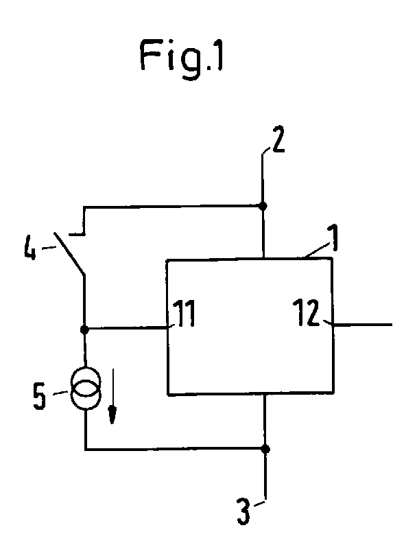
Description
Die Erfindung betrifft eine Anordnung zur dauerhaft betriebssicheren Anschaltung eines Kontaktsatzes einer elektromechanischen Schaltkontakteinrichtung an einen Eingang einer leistungsaufnahmebegrenzten Auswerteschaltung für binäre Informationen.The invention relates to an arrangement for the permanently reliable connection of a contact set of an electromechanical switch contact device to an input of a power-limited evaluation circuit for binary information.
Derartige Kontaktsätze von elektromechanischen Schaltkontakteinrichtungen gehören systematisch der Gruppe der binäre Sensoren an. Zur Vernetzung derartiger binärer Sensoren in der Feldebene ist aus dem Beitrag ![]()
![]()
Aufgrund der geringen Oberfläche des SMD-Gehäuses ist aus thermischen Gründen, wie aus dem Technischen Gerätepaß für das ASI-Moduloberteil 3RG9001-0AG00 der Firma Siemens bekannt, die Stromversorgung für jeden angeschlossenen Aktuator/Sensor auf 5 mA begrenzt.Due to the small surface area of the SMD housing, the power supply for each connected actuator / sensor is limited to 5 mA for thermal reasons, as is known from the technical device pass for the ASI module upper part 3RG9001-0AG00 from Siemens.
Die begrenzte Stromstärke hat zur Folge, daß insbesondere bei den als Sensor wirkenden Kontaktsätzen von elektromechanischen Schaltkontakteinrichtungen, wie sie beispielsweise als robuste Endlagenschalter in Einrichtungen des Maschinenbaus eingesetzt werden, in Ermangelung ausreichender Stromstärke der Selbstreinigungseffekt ausbleibt, so daß bereits nach kurzer Betriebsdauer der Kontaktübertragungswiderstand zwischen den Kontakten eines Kontaktsatzes so weit steigt, daß eine eindeutige Identifizierung, ob die Kontakte geöffnet oder geschlossen sind, nicht mehr möglich ist.The limited current strength means that, in particular in the case of contact sets of electromechanical switch contact devices acting as sensors, such as those used as robust limit switches in mechanical engineering facilities, the self-cleaning effect does not occur in the absence of sufficient current strength, so that after a short operating time the contact transmission resistance between the Contacts of a contact set increases to such an extent that it is no longer possible to clearly identify whether the contacts are open or closed.
Der Erfindung liegt daher die Aufgabe zugrunde, eine Anordnung mit einem als Sensor wirkenden Kontaktsatz einer elektromechanischen Schaltkontakteinrichtung an einer ASI-Auswerteschaltung so zu verbessern, daß eine dauerhafte Betriebssicherheit gewährleistet ist.The invention is therefore based on the object of improving an arrangement with a contact set, acting as a sensor, of an electromechanical switch contact device on an ASI evaluation circuit in such a way that permanent operational reliability is ensured.
Erfindungsgemäß wird diese Aufgabe mit den Mitteln des Patentanspruchs 1 gelöst. Eine vorteilhafte Ausgestaltung der Erfindung ist in dem Patentanspruch 2 beschrieben.According to the invention, this object is achieved with the means of claim 1. An advantageous embodiment of the invention is described in
Das Wesen der Erfindung besteht darin, dem Kontaktsatz der elektromechanischen Schaltkontakteinrichtung einen von der ASI-Auswerteschaltung unabhängigen Strom aufzuprägen, der an die speziellen Eigenschaften der Schaltkontakteinrichtung anpaßbar ist. Vorteilhafterweise ist dadurch eine vorbekannte, verfügbare ASI-Auswerteschaltung mit vorgegebener Strombegrenzung auch in Zusammenschaltung mit Schaltkontakteinrichtungen, die zur Selbstreinigung einer Mindeststromstärke bedürfen, die oberhalb der Strombegrenzung der ASI-Auswerteschaltung liegt, verwendbar.The essence of the invention is to impress the contact set of the electromechanical switch contact device with a current that is independent of the ASI evaluation circuit and that can be adapted to the special properties of the switch contact device. Advantageously, a previously known, available ASI evaluation circuit with a predetermined current limitation can also be used in connection with switching contact devices which require a minimum current for self-cleaning, which is above the current limitation of the ASI evaluation circuit.
Die Erfindung wird nachstehend anhand eines Ausführungsbeispiels näher erläutert. Dazu ist in Figur 1 ein Prinzipschaltbild mit den erfindungswesentlichen Schaltmitteln dargestellt. Eine Auswerteschaltung 1 ist an einen ersten Betriebsspannungsanschluß 2 und einen zweiten Betriebsspannungsanschluß 3 angeschlossen und weist einen Eingang 11 und einen Ausgang 12 auf. An den ersten und den zweiten Betriebsspannungsanschluß 2 und 3 ist eine nicht dargestellte Betriebsspannungsquelle angeschlossen. Weiterhin ist eine Schaltkontakteinrichtung 4 dargestellt, die einen schaltbaren Kontaktsatz aufweist, dessen Schaltzustand zu überwachen ist. Der Zustand des Kontaktsatzes der Schaltkontakteinrichtung 4 ist als logischer Pegel am Ausgang 12 der Auswerteschaltung 1 abgreifbar. Diese Schaltkontakteinrichtung ist als Endlagenschalter in Einrichtungen des Maschinenbaus ausgeführt. Der zu überwachende Kontaktsatz der Schaltkontakteinrichtung 4 ist zwischen den ersten Betriebsspannungsanschluß 2 und den Eingang 11 der Auswerteschaltung 1 geschaltet.The invention is explained in more detail below using an exemplary embodiment. For this purpose, a basic circuit diagram is shown in Figure 1 with the switching means essential to the invention. An evaluation circuit 1 is connected to a first
Erfindungsgemäß ist darüber hinaus eine Stromquelle 5 vorgesehen, die in Reihe mit dem Kontaktsatz der Schaltkontakteinrichtung 4 zwischen den ersten Betriebsspannungsanschluß 2 und den zweiten Betriebsspannungsanschluß 3 geschaltet ist. In der dargestellten Ausführungsform ist die Stromquelle zwischen den Eingang 11 der Auswerteschaltung 1 und den zweiten Betriebsspannungsanschluß 3 geschaltet.According to the invention, a current source 5 is also provided, which is connected in series with the contact set of the switching contact device 4 between the first
Bei geschlossenem Kontaktsatz der Schaltkontakteinrichtung 4 wird der Kontaktsatz von einem Strom durchflossen, der sich additiv aus dem Eingangsstrom der Auswerteschaltung 1 am Eingang 11 und dem Strom durch die Stromquelle 5 zusammensetzt. Der Eingangsstrom der Auswerteschaltung 1 am Eingang 11 ist systembedingt vorgegeben begrenzt. Der Quellenstrom der Stromquelle 5 ist so einstellbar, daß der Summenstrom durch den Kontaktsatz der Schaltkontakteinrichtung 4 im geschlossenen Zustand den für den speziell eingesetzten Schaltkontakt erforderlichen und bekannten Strom zur Erzielung des Selbstreinigungseffektes mindestens erreicht. Durch Realisierung des für sich bekannten Selbstreinigungseffektes der Kontakte des Kontaktsatzes auch für Schaltkontakteinrichtungen 4, bei denen der zur Selbstreinigung erforderliche Mindeststrom größer als der vorgegebene, maximale Strom der Auswerteschaltung 1 ist, wird auch für diese Spezies von Schaltkontakteinrichtungen 4 eine dauerhafte Betriebssicherheit an ASI-Auswerteschaltungen darstellbar.When the contact set of the switching contact device 4 is closed, a current flows through the contact set, which is additively composed of the input current of the evaluation circuit 1 at the
Im geöffneten Zustand des Kontaktsatzes der Schaltkontakteinrichtung 4 ist das Potential am Eingang 11 der Auswerteschaltung 1 im wesentlichen gleich dem Potential am zweiten Betriebsspannungsanschluß 3, so daß die Stromquelle 5 gegenüber der Auswerteschaltung 1 wirkungslos ist.In the opened state of the contact set of the switch contact device 4, the potential at the
Der Vorteil der Erfindung ist insbesondere darin zu sehen, daß die aufwendige Gestaltung einer besonderen Auswerteschaltung 1 für das Aktuator-Sensor-Interface ASI für spezielle Eigenschaften von Schaltkontakteinrichtungen 4 vermieden wird.The advantage of the invention can be seen in particular in the fact that the complex design of a special evaluation circuit 1 for the actuator-sensor interface ASI for special properties of switch contact devices 4 is avoided.
Claims (2)
dadurch gekennzeichnet,
daß eine Stromquelle (5) in Reihe zu dem Kontaktsatz der elektromechanischen Schaltkontakteinrichtung (4) und zwischen den Eingang (11) der Auswerteschaltung (1) und einem zweiten Betriebsspannungsanschluß (3) geschaltet ist.Arrangement for the permanently reliable connection of a contact set of an electromechanical switch contact device to a power-limited evaluation circuit for binary information according to the actuator sensor interface ASI, the switch contact device being connected between a first operating voltage connection and the input of the evaluation circuit,
characterized by
that a current source (5) is connected in series with the contact set of the electromechanical switch contact device (4) and between the input (11) of the evaluation circuit (1) and a second operating voltage connection (3).
dadurch gekennzeichnet,
daß die Stromquelle (5) durch einen ohmschen Widerstand gebildet ist.Arrangement according to claim 1
characterized by
that the current source (5) is formed by an ohmic resistor.
Applications Claiming Priority (2)
| Application Number | Priority Date | Filing Date | Title |
|---|---|---|---|
| DE1995145254 DE19545254C2 (en) | 1995-11-24 | 1995-11-24 | Arrangement for the permanently reliable connection of a contact set of an electromechanical switch contact device |
| DE19545254 | 1995-11-24 |
Publications (2)
| Publication Number | Publication Date |
|---|---|
| EP0776017A2 true EP0776017A2 (en) | 1997-05-28 |
| EP0776017A3 EP0776017A3 (en) | 1998-07-29 |
Family
ID=7779179
Family Applications (1)
| Application Number | Title | Priority Date | Filing Date |
|---|---|---|---|
| EP96250265A Withdrawn EP0776017A3 (en) | 1995-11-24 | 1996-11-21 | Device for the reliable and permanent connection of a contact pair of an electromechanical switching device |
Country Status (2)
| Country | Link |
|---|---|
| EP (1) | EP0776017A3 (en) |
| DE (1) | DE19545254C2 (en) |
Cited By (1)
| Publication number | Priority date | Publication date | Assignee | Title |
|---|---|---|---|---|
| JP2016073004A (en) * | 2014-09-26 | 2016-05-09 | 三菱電機株式会社 | Protective relay device |
Families Citing this family (2)
| Publication number | Priority date | Publication date | Assignee | Title |
|---|---|---|---|---|
| DE102012207592A1 (en) * | 2012-05-08 | 2013-11-14 | Robert Bosch Gmbh | Circuit arrangement has control unit that detects switching state of relay, which is arranged such that relay is actuated several times by control device upon detection of break contact when relay is closed |
| DE102015016992B4 (en) | 2015-12-24 | 2017-09-28 | Audi Ag | Method for cleaning electrical contacts of an electrical switching device and motor vehicle |
Family Cites Families (4)
| Publication number | Priority date | Publication date | Assignee | Title |
|---|---|---|---|---|
| DE1154554B (en) * | 1962-02-23 | 1963-09-19 | Licentia Gmbh | Arrangement for achieving reliable contact with a mechanical contact arrangement |
| DE3228686A1 (en) * | 1982-07-31 | 1984-02-02 | Edmund 7016 Gerlingen Zottnik | Method and device for detecting switch positions |
| DE4015271A1 (en) * | 1990-05-12 | 1991-11-14 | Vdo Schindling | CIRCUIT ARRANGEMENT FOR INQUIRING SWITCH POSITIONS |
| DE4318188A1 (en) * | 1993-06-01 | 1994-12-08 | Abb Management Ag | Device for monitoring a switch position |
-
1995
- 1995-11-24 DE DE1995145254 patent/DE19545254C2/en not_active Expired - Fee Related
-
1996
- 1996-11-21 EP EP96250265A patent/EP0776017A3/en not_active Withdrawn
Cited By (1)
| Publication number | Priority date | Publication date | Assignee | Title |
|---|---|---|---|---|
| JP2016073004A (en) * | 2014-09-26 | 2016-05-09 | 三菱電機株式会社 | Protective relay device |
Also Published As
| Publication number | Publication date |
|---|---|
| EP0776017A3 (en) | 1998-07-29 |
| DE19545254C2 (en) | 2000-09-07 |
| DE19545254A1 (en) | 1997-05-28 |
Similar Documents
| Publication | Publication Date | Title |
|---|---|---|
| DE69108394T2 (en) | ELECTRONIC AUXILIARY CONTACT FOR A PROTECTOR. | |
| DE102011018229B4 (en) | Circuit arrangement and method for electrical isolation of an electrical device from the network | |
| EP0776017A2 (en) | Device for the reliable and permanent connection of a contact pair of an electromechanical switching device | |
| EP1920220A2 (en) | Position sensor and method for operating a position sensor | |
| EP1347388B1 (en) | Coupling device for connecting devices to a bus system | |
| DE102019203111A1 (en) | Motor vehicle control device with connection and disconnection function for at least one electrical consumer to be controlled by the motor vehicle control device | |
| EP1845548B1 (en) | Installation, switching assembly and method for insulation and earth connection surveillance in an non-grounded system | |
| DE10124910B4 (en) | Device and method for detecting switching states and for reducing quiescent currents of switching devices | |
| EP1776518B1 (en) | Sensor for measuring the position of an actuator | |
| DE102022132058A1 (en) | Linear, inductive position and break detection sensor | |
| EP3652860A1 (en) | Level converter and a method for converting level values in vehicle control devices | |
| EP1755135A2 (en) | Circuit arrangement for the collection and evaluation of electrical and physical measured variables in an electrical switchgear | |
| DE19813952C1 (en) | Signaling output stage for generating digital voltage signals on a bus system | |
| EP2045825A1 (en) | Switching element | |
| DE102006043839A1 (en) | Sensor system for e.g. seat belt lock, of motor vehicle for detecting such as seat position, has sensor devices interconnected with comparator circuit such that information about total-current strength is supplied via signal line of circuit | |
| EP0298329A2 (en) | Electronic switching device, preferably operating without contact | |
| DE3938219C2 (en) | ||
| EP0558813B1 (en) | Method and device for controlling an electric component and for error feedback signaling | |
| DE102013112300A1 (en) | Input circuit for providing a supply voltage | |
| DE19619904C2 (en) | Electronic, preferably non-contact switching device | |
| DE2910897C2 (en) | Tester for a telephone switching system for testing the subscriber line | |
| EP1273924B1 (en) | Device for the detection of electrically conducting contamination of the contact side of an electric connector | |
| EP0372256B1 (en) | Method for the projection of a transformer and device for carrying out the method | |
| DE102024110258A1 (en) | Intelligent switching device | |
| DE19621567C2 (en) | Controllable loading device |
Legal Events
| Date | Code | Title | Description |
|---|---|---|---|
| PUAI | Public reference made under article 153(3) epc to a published international application that has entered the european phase |
Free format text: ORIGINAL CODE: 0009012 |
|
| AK | Designated contracting states |
Kind code of ref document: A2 Designated state(s): AT BE CH DE ES FR GB IE IT LI NL PT SE |
|
| PUAL | Search report despatched |
Free format text: ORIGINAL CODE: 0009013 |
|
| AK | Designated contracting states |
Kind code of ref document: A3 Designated state(s): AT BE CH DE ES FR GB IE IT LI NL PT SE |
|
| 17P | Request for examination filed |
Effective date: 19981112 |
|
| STAA | Information on the status of an ep patent application or granted ep patent |
Free format text: STATUS: THE APPLICATION HAS BEEN WITHDRAWN |
|
| 18W | Application withdrawn |
Withdrawal date: 20010215 |