EP0776000B1 - Information reading system - Google Patents
Information reading system Download PDFInfo
- Publication number
- EP0776000B1 EP0776000B1 EP96118767A EP96118767A EP0776000B1 EP 0776000 B1 EP0776000 B1 EP 0776000B1 EP 96118767 A EP96118767 A EP 96118767A EP 96118767 A EP96118767 A EP 96118767A EP 0776000 B1 EP0776000 B1 EP 0776000B1
- Authority
- EP
- European Patent Office
- Prior art keywords
- signal
- information
- detecting
- low frequency
- recording medium
- Prior art date
- Legal status (The legal status is an assumption and is not a legal conclusion. Google has not performed a legal analysis and makes no representation as to the accuracy of the status listed.)
- Expired - Lifetime
Links
Images


Classifications
-
- G—PHYSICS
- G11—INFORMATION STORAGE
- G11B—INFORMATION STORAGE BASED ON RELATIVE MOVEMENT BETWEEN RECORD CARRIER AND TRANSDUCER
- G11B7/00—Recording or reproducing by optical means, e.g. recording using a thermal beam of optical radiation by modifying optical properties or the physical structure, reproducing using an optical beam at lower power by sensing optical properties; Record carriers therefor
- G11B7/08—Disposition or mounting of heads or light sources relatively to record carriers
- G11B7/09—Disposition or mounting of heads or light sources relatively to record carriers with provision for moving the light beam or focus plane for the purpose of maintaining alignment of the light beam relative to the record carrier during transducing operation, e.g. to compensate for surface irregularities of the latter or for track following
- G11B7/0943—Methods and circuits for performing mathematical operations on individual detector segment outputs
-
- G—PHYSICS
- G11—INFORMATION STORAGE
- G11B—INFORMATION STORAGE BASED ON RELATIVE MOVEMENT BETWEEN RECORD CARRIER AND TRANSDUCER
- G11B7/00—Recording or reproducing by optical means, e.g. recording using a thermal beam of optical radiation by modifying optical properties or the physical structure, reproducing using an optical beam at lower power by sensing optical properties; Record carriers therefor
- G11B7/08—Disposition or mounting of heads or light sources relatively to record carriers
- G11B7/09—Disposition or mounting of heads or light sources relatively to record carriers with provision for moving the light beam or focus plane for the purpose of maintaining alignment of the light beam relative to the record carrier during transducing operation, e.g. to compensate for surface irregularities of the latter or for track following
- G11B7/0901—Disposition or mounting of heads or light sources relatively to record carriers with provision for moving the light beam or focus plane for the purpose of maintaining alignment of the light beam relative to the record carrier during transducing operation, e.g. to compensate for surface irregularities of the latter or for track following for track following only
-
- G—PHYSICS
- G11—INFORMATION STORAGE
- G11B—INFORMATION STORAGE BASED ON RELATIVE MOVEMENT BETWEEN RECORD CARRIER AND TRANSDUCER
- G11B7/00—Recording or reproducing by optical means, e.g. recording using a thermal beam of optical radiation by modifying optical properties or the physical structure, reproducing using an optical beam at lower power by sensing optical properties; Record carriers therefor
- G11B7/08—Disposition or mounting of heads or light sources relatively to record carriers
- G11B7/09—Disposition or mounting of heads or light sources relatively to record carriers with provision for moving the light beam or focus plane for the purpose of maintaining alignment of the light beam relative to the record carrier during transducing operation, e.g. to compensate for surface irregularities of the latter or for track following
- G11B7/094—Methods and circuits for servo offset compensation
-
- G—PHYSICS
- G11—INFORMATION STORAGE
- G11B—INFORMATION STORAGE BASED ON RELATIVE MOVEMENT BETWEEN RECORD CARRIER AND TRANSDUCER
- G11B19/00—Driving, starting, stopping record carriers not specifically of filamentary or web form, or of supports therefor; Control thereof; Control of operating function ; Driving both disc and head
- G11B19/02—Control of operating function, e.g. switching from recording to reproducing
- G11B19/12—Control of operating function, e.g. switching from recording to reproducing by sensing distinguishing features of or on records, e.g. diameter end mark
Definitions
- the present invention relates to an information reading system, according to the preamble of claim 1.
- a laser beam from a laser beam source is converged through an objective lens so that an information reading point is formed on an optical disc. Then, light reflected from the optical disc is received so that it is possible to read information recorded on the recording medium, also to perform focusing control and tracking control on an actuator.
- Fig. 3 shows an optical tracking servo circuit using a DPP (Differential Push-pull) method, which circuit is incorporated in a conventional information reading system.
- a main beam is directed to an optical disc to read information therefrom and to obtain focus error signal.
- two sub-beams are also directed to the same optical disc to obtain tracking error signal.
- reflected light (reflected from disc surface) of the main beam and the sub-beams are detected and received respectively by a main detector 1 and two sub-detectors 2, 3.
- a reflected light of the main beam is detected and received by the main detector 1 having light receiving sections a , b , c , and d .
- reflected light of one sub-beam is detected and received by a sub-detector 2 having light receiving sections e and f
- a sub-detector 3 having light receiving sections g and h .
- the tracking servo circuit shown in Fig. 3 includes a tracking error signal generating circuit.
- Such tracking error signal generating circuit comprises: a first subtractor 4 provided to receive output signals from the light receiving sections e and f of the sub-detector 2 and to subtract one output signal (from the light receiving section f ) from the other output signal (from the light receiving section e ) so as to produce a first difference signal; a second subtractor 5 provided to receive output signals from the light receiving sections g and h of the sub-detector 3 and to subtract one output signal (from the light receiving section h ) from the other output signal (from the light receiving section g ) so as to produce a second difference signal; a calculator 6 provided to receive output signals from the light receiving sections a, b, c and d of the main detector 1 and to perform a calculation of (a sum of signals from the right receiving sections a and b ) - (a sum of signals from the left receiving sections c and d ) so as to produce a
- the value of the constant K of the multiplier 8 would be set in accordance with light amounts detected and received by the main detector 1 and sub-detectors 2 and 3.
- the tracking error signal produced by the third subtractor 9 is used to indicate a deviation of an information detecting point (a spot position of the main beam on an optical disc) from an information track.
- a tracking error signal is fed from the third subtractor 9 to a driver 13 which in turn produces an output signal to drive an actuator 14 so as to perform a desired tracking control.
- a CD-R disc (called CD-Recorder that is a recordable disc) is used as an information recording medium
- a CD-R will have a plurality of pregrooves formed on one surface of the disc for recording information, and such pregrooves will have a waviness having a central frequency of 22.05 kHz.
- ATIP Absolute Time In Pregroove
- information is recorded on the disc by FM-modulating the central frequency of the waviness.
- the ATIP information can be read out by extracting an envelope signal enclosing a difference signal of [(a sum of signals from the right receiving sections a and b) - (a sum of signals from the left receiving sections c and d)] produced by the calculator 6.
- a detector such as the main detector 1 should be appropriately adjusted such that a vertical dividing line of the main detector 1 will be coincident with an optical axis of a reflected light of the main beam, as shown in Fig. 5b.
- the optical axis of the reflected light will shift from a condition shown in Fig. 5b to a condition shown in Fig. 5a indicating a deviation of the optical axis from the vertical dividing line.
- ATIP information is to be read out from a CD-R (having information pits formed thereon) under the condition shown in Fig. 5a, RF signal from the information pits will be undesirably mixed into the ATIP information. As a result, the reading of the ATIP information will become difficult.
- a difference signal produced by the calculator 6 will be interfered and like that shown in Fig. 6a.
- Such a difference signal shown in Fig. 6a contains RF signals from information pits, which has a higher frequency than that of ATIP information.
- the RF signal will not be mixed into the difference signal, thus obtaining an uninterfered difference signal as shown in Fig. 6b.
- the RF signal from the information pits is contained in a difference signal produced by the calculator 6, the RF signal will become a noise interfering ATIP information. As a result, the RF signal will be mixed into the ATIP information, hence there is a possibility that the ATIP information may not be correctly read out.
- An information reading system is known from WO91-08568. Similar systems are also known from DE-A-3 643 572 and FR-A-2 544 535.
- an object of the present invention to provide an improved information reading system capable of controlling an actuator so that an optical axis of reflected light from an information recording medium will be kept coincident with a dividing line of a light detector.
- an information reading system comprising the features of claim 1. Further developments of the information reading system according to the invention are specified in the subclaims.
- Fig. 1 is a block diagram showing an embodiment of the present invention, which is an improved tracking servo circuit for use in an information reading system.
- the tracking servo circuit of the present invention is similar to the above-discussed conventional tracking servo circuit, except that the tracking servo circuit of the present invention further includes a low-pass filter 10, a switch 11 and an adder 12.
- the low-pass filter 10 which serves to act as a low frequency signal detecting/passing means, is provided to receive the calculation result signal from the calculator 6 and to output low frequency components initially contained in the calculation result signal.
- a cut-off frequency of the low-pass filter 10 may be set such that it is possible to cut off a signal component representing a rotation deviation of an optical disc and having a high frequency, and that a light axis deviation signal of a low frequency may be extracted therefrom to indicate a deviation of the optical axis of a reflected light from a vertical dividing line on the detector 1.
- the cut-off frequency of the low-pass filter 10 may be set at about 1 kHz
- the switch 11 is provided to be controlled by a controller (not shown) so as to selectively apply an output signal from the low-pass filter 10 to the adder 12.
- the adder 12 is provided to add together the output signal from the low-pass filter 10 and a tracking error signal from the third subtractor 9.
- the tracking servo circuit as shown in Fig. 1 is turned on.
- the calculating result signal from the calculator 6 will contain relatively high frequency signals in a frequency band of 5 - 10 kHz and low frequency signals which are almost direct current components.
- the relatively high frequency signals in a frequency band 5 - 10 kHz will contain a signal component representing a rotation deviation of an optical disc, whilst the low frequency signals which are almost direct current components will contain a signal representing a deviation of an optical axis.
- the optical axis deviation signal is then selectively fed through the switch 11 to the adder 12, so as to be added to the tracking error signal from the third subtractor 9, thereby producing an added signal through the adder 12.
- the added signal is fed from the adder 12 to the driver 13 which in turn produces an output signal to drive the actuator 14 to perform a desired tracking control, so that a deviation of the optical axis of a reflected light from the vertical dividing line on the main detector 1 may be reduced to zero.
- the switch 11 is controlled by a controller (not shown) in a manner such that the switch 11 is closed only when there will be a problem caused by a deviation of the optical axis of reflected light from the vertical dividing line on the main detector 1. For instance, the switch 11 is controlled to be closed when it is necessary to read ATIP information recorded on an optical disc during reproduction of an unfinalized CD-R (a recordable disc having no TOC information recorded thereon). On the other hand, if a finalized CD-R (a recordable disc having TOC information recorded thereon, and also having information pits representing main information formed thereon) is to be reproduced without a need for reproducing ATIP information, the switch 11 is controlled by the same controller so as to be opened. At this moment, since only normal tracking servo control is needed, the actuator 14 is controlled only by a tracking error signal from the third subtractor 9.
- an optical axis deviation signal is selectively added to the tracking error signal depending upon the kind of an information to be read out
- an optical axis deviation signal may be selectively added to the tracking error signal in accordance with a discriminating result of a recording medium discriminating means (not shown) provided to identify the kind of an information recording medium. For instance, when reproducing a CD-R, since it is usually necessary that the ATIP information should be reproduced, the controller will operate such that an optical axis deviation signal may be fed to the adder 12. On the other hand, when reproducing a CD not containing ATIP information, the controller will not operate to cause an optical axis deviation signal to be fed to the adder 12.
- a DPP method is used in the tracking error detection, it is also possible to employ other methods such as a three-beam method or a phase-differential method.
- the actuator 14 may be controlled such that during the reproduction of a CD, the optical axis deviation signal from the focus error detector is added to the tracking error signal, so as to prohibit an optical axis deviation from a vertical dividing line on the main detector 1.
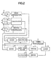
- Fig. 2 is a block diagram showing another embodiment of the present invention, which is another improved tracking servo circuit for use in an information reading system.
- the tracking servo circuit shown in Fig. 2 is almost the same as the tracking servo circuit shown in Fig. 1, except that the tracking servo circuit shown in Fig. 2 includes a further adder 15. As shown in Fig. 2, the adder 15 is provided to receive and add together the calculation signal from the calculator 6 and the output signal from the multiplier 8. An added signal is fed from the adder 15 to the low-pass filter 10.
- the added signal including the calculation signal from the calculator 6 and the output signal from the multiplier 8, upon being fed to the low-pass filter 10, will produce an optical axis deviation signal having a higher level than that of the optical axis deviation signal (extracted only from the calculation signal fed from the calculator 6) produced from the low-pass filter 11 in the tracking servo circuit shown in Fig. 1.
Description
- The present invention relates to an information reading system, according to the preamble of
claim 1. - As is well known, in a conventional information reading system for optically reading information recorded on an optical disc, a laser beam from a laser beam source is converged through an objective lens so that an information reading point is formed on an optical disc. Then, light reflected from the optical disc is received so that it is possible to read information recorded on the recording medium, also to perform focusing control and tracking control on an actuator.
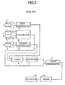
- Fig. 3 shows an optical tracking servo circuit using a DPP (Differential Push-pull) method, which circuit is incorporated in a conventional information reading system. In practice, a main beam is directed to an optical disc to read information therefrom and to obtain focus error signal. Meanwhile, two sub-beams are also directed to the same optical disc to obtain tracking error signal. Then, reflected light (reflected from disc surface) of the main beam and the sub-beams are detected and received respectively by a
main detector 1 and twosub-detectors main detector 1 having light receiving sections a, b, c, and d. At the same time, reflected light of one sub-beam is detected and received by asub-detector 2 having light receiving sections e and f, whilst other reflected light of the other sub-beam is detected and received by asub-detector 3 having light receiving sections g and h. - The tracking servo circuit shown in Fig. 3 includes a tracking error signal generating circuit. Such tracking error signal generating circuit comprises: a
first subtractor 4 provided to receive output signals from the light receiving sections e and f of thesub-detector 2 and to subtract one output signal (from the light receiving section f) from the other output signal (from the light receiving section e) so as to produce a first difference signal; asecond subtractor 5 provided to receive output signals from the light receiving sections g and h of thesub-detector 3 and to subtract one output signal (from the light receiving section h) from the other output signal (from the light receiving section g) so as to produce a second difference signal; acalculator 6 provided to receive output signals from the light receiving sections a, b, c and d of themain detector 1 and to perform a calculation of (a sum of signals from the right receiving sections a and b) - (a sum of signals from the left receiving sections c and d) so as to produce a calculation result signal; anadder 7 for adding together the first difference signal (from the first subtractor 4) and the second difference signal (from the second subtract 5) so as to produce an added signal; amultiplier 8 for multiplying the added signal (from the adder 7) with a predetermined constant K so as to produce a multiplied signal; athird subtractor 9 for subtracting the multiplied signal from the above calculation result signal so as to produce a tracking error signal. - Here, the value of the constant K of the
multiplier 8 would be set in accordance with light amounts detected and received by themain detector 1 andsub-detectors - The tracking error signal produced by the
third subtractor 9 is used to indicate a deviation of an information detecting point (a spot position of the main beam on an optical disc) from an information track. Such a tracking error signal is fed from thethird subtractor 9 to adriver 13 which in turn produces an output signal to drive anactuator 14 so as to perform a desired tracking control. - However, as shown in Fig. 4, if a CD-R disc (called CD-Recorder that is a recordable disc) is used as an information recording medium, such a CD-R will have a plurality of pregrooves formed on one surface of the disc for recording information, and such pregrooves will have a waviness having a central frequency of 22.05 kHz. Usually, ATIP (Absolute Time In Pregroove) information is recorded on the disc by FM-modulating the central frequency of the waviness.
- On the other hand, the ATIP information can be read out by extracting an envelope signal enclosing a difference signal of [(a sum of signals from the right receiving sections a and b) - (a sum of signals from the left receiving sections c and d)] produced by the
calculator 6. - Usually, a detector such as the
main detector 1 should be appropriately adjusted such that a vertical dividing line of themain detector 1 will be coincident with an optical axis of a reflected light of the main beam, as shown in Fig. 5b. However, due to a possible adjustment error or a possible temperature change, the optical axis of the reflected light will shift from a condition shown in Fig. 5b to a condition shown in Fig. 5a indicating a deviation of the optical axis from the vertical dividing line. If ATIP information is to be read out from a CD-R (having information pits formed thereon) under the condition shown in Fig. 5a, RF signal from the information pits will be undesirably mixed into the ATIP information. As a result, the reading of the ATIP information will become difficult. - In detail, when the optical axis of a reflected light is deviated from the vertical dividing line on the
main detector 1, a difference signal produced by thecalculator 6 will be interfered and like that shown in Fig. 6a. Such a difference signal shown in Fig. 6a contains RF signals from information pits, which has a higher frequency than that of ATIP information. On the other hand, when the optical axis of a reflected light is coincident with the vertical dividing line on themain detector 1, the RF signal will not be mixed into the difference signal, thus obtaining an uninterfered difference signal as shown in Fig. 6b. - If the RF signal from the information pits is contained in a difference signal produced by the
calculator 6, the RF signal will become a noise interfering ATIP information. As a result, the RF signal will be mixed into the ATIP information, hence there is a possibility that the ATIP information may not be correctly read out. - An information reading system according to the preamble of
claim 1 is known from WO91-08568. Similar systems are also known from DE-A-3 643 572 and FR-A-2 544 535. - In view of the above problems existing in the abovementioned prior art, it is an object of the present invention to provide an improved information reading system capable of controlling an actuator so that an optical axis of reflected light from an information recording medium will be kept coincident with a dividing line of a light detector.
- According to the invention, an information reading system is disclosed comprising the features of
claim 1. Further developments of the information reading system according to the invention are specified in the subclaims. - The above objects and features of the present invention will become more understood from the following description with reference to the accompanying drawings.
-
- Fig. 1 is a block diagram showing an embodiment of the present invention, which is an improved tracking servo circuit for use in an information reading system.
- Fig. 2 is a block diagram showing another embodiment of the present invention, which is another improved tracking servo circuit for use in an information reading system.
- Fig. 3 is a block diagram showing a conventional tracking servo circuit for use in a conventional information reading system.
- Fig. 4 is a schematic explanatory view showing a structure of a CD-R disc.
- Fig. 5a is a schematic explanatory view showing a deviation of an optical axis of reflected light from a dividing line on a main light detector.
- Fig. 5b is a schematic explanatory view showing a coincidence of an optical axis of reflected light with a dividing line on a main light detector.
- Fig. 6a is a graph showing a difference signal produced by a calculator connected with the main light detector when there is a deviation between an optical axis of reflected light and a dividing line on the main light detector.
- Fig. 6b is a graph showing a difference signal produced by a calculator connected with the main light detector when an optical axis of reflected light is coincident with a dividing line on the main light detector.
- The preferred embodiments of the present invention will be described in detail below with reference to Figs. 1 and 2, in which identical elements as those in Fig. 3 will be represented by the same reference numerals, and the same explanation thereof will be omitted.
- Fig. 1 is a block diagram showing an embodiment of the present invention, which is an improved tracking servo circuit for use in an information reading system. As shown in Fig. 1, the tracking servo circuit of the present invention is similar to the above-discussed conventional tracking servo circuit, except that the tracking servo circuit of the present invention further includes a low-
pass filter 10, aswitch 11 and anadder 12. - The low-
pass filter 10, which serves to act as a low frequency signal detecting/passing means, is provided to receive the calculation result signal from thecalculator 6 and to output low frequency components initially contained in the calculation result signal. In detail, a cut-off frequency of the low-pass filter 10 may be set such that it is possible to cut off a signal component representing a rotation deviation of an optical disc and having a high frequency, and that a light axis deviation signal of a low frequency may be extracted therefrom to indicate a deviation of the optical axis of a reflected light from a vertical dividing line on thedetector 1. For instance, if the information reading system is a usual CD-R player, the cut-off frequency of the low-pass filter 10 may be set at about 1 kHz - The
switch 11 is provided to be controlled by a controller (not shown) so as to selectively apply an output signal from the low-pass filter 10 to theadder 12. - The
adder 12 is provided to add together the output signal from the low-pass filter 10 and a tracking error signal from thethird subtractor 9. - The operation of the tracking servo circuit according to the present invention will be described in detail below with reference to Fig. 1.
- When a CD or a CD-R is to be reproduced, the tracking servo circuit as shown in Fig. 1 is turned on. At this time, the calculating result signal from the
calculator 6 will contain relatively high frequency signals in a frequency band of 5 - 10 kHz and low frequency signals which are almost direct current components. The relatively high frequency signals in a frequency band 5 - 10 kHz will contain a signal component representing a rotation deviation of an optical disc, whilst the low frequency signals which are almost direct current components will contain a signal representing a deviation of an optical axis. - When such calculating result signal is passed through the low-
pass filter 10, signal components having frequencies higher than that of the disc rotation deviation signal will be cut off, only permitting the passing of the signal representing a deviation of an optical axis. - The optical axis deviation signal is then selectively fed through the
switch 11 to theadder 12, so as to be added to the tracking error signal from thethird subtractor 9, thereby producing an added signal through theadder 12. The added signal is fed from theadder 12 to thedriver 13 which in turn produces an output signal to drive theactuator 14 to perform a desired tracking control, so that a deviation of the optical axis of a reflected light from the vertical dividing line on themain detector 1 may be reduced to zero. - Here, the
switch 11 is controlled by a controller (not shown) in a manner such that theswitch 11 is closed only when there will be a problem caused by a deviation of the optical axis of reflected light from the vertical dividing line on themain detector 1. For instance, theswitch 11 is controlled to be closed when it is necessary to read ATIP information recorded on an optical disc during reproduction of an unfinalized CD-R (a recordable disc having no TOC information recorded thereon). On the other hand, if a finalized CD-R (a recordable disc having TOC information recorded thereon, and also having information pits representing main information formed thereon) is to be reproduced without a need for reproducing ATIP information, theswitch 11 is controlled by the same controller so as to be opened. At this moment, since only normal tracking servo control is needed, theactuator 14 is controlled only by a tracking error signal from thethird subtractor 9. - Although in the above embodiment it has been described that an optical axis deviation signal is selectively added to the tracking error signal depending upon the kind of an information to be read out, it is also possible that an optical axis deviation signal may be selectively added to the tracking error signal in accordance with a discriminating result of a recording medium discriminating means (not shown) provided to identify the kind of an information recording medium. For instance, when reproducing a CD-R, since it is usually necessary that the ATIP information should be reproduced, the controller will operate such that an optical axis deviation signal may be fed to the
adder 12. On the other hand, when reproducing a CD not containing ATIP information, the controller will not operate to cause an optical axis deviation signal to be fed to theadder 12. - Further, although in the above embodiment, a DPP method is used in the tracking error detection, it is also possible to employ other methods such as a three-beam method or a phase-differential method.
- Moreover, although in the above embodiment, merely the tracking error signal is used to control the
actuator 14, but if a Knife-edge method is used to detect focus error at the same time, an optical axis deviation on a detector for detecting focus error will cause an offset in a focus error signal, thus theactuator 14 may be controlled such that during the reproduction of a CD, the optical axis deviation signal from the focus error detector is added to the tracking error signal, so as to prohibit an optical axis deviation from a vertical dividing line on themain detector 1. - Fig. 2 is a block diagram showing another embodiment of the present invention, which is another improved tracking servo circuit for use in an information reading system.
- The tracking servo circuit shown in Fig. 2 is almost the same as the tracking servo circuit shown in Fig. 1, except that the tracking servo circuit shown in Fig. 2 includes a
further adder 15. As shown in Fig. 2, theadder 15 is provided to receive and add together the calculation signal from thecalculator 6 and the output signal from themultiplier 8. An added signal is fed from theadder 15 to the low-pass filter 10. - Since the output signal from the
multiplier 8 also contains low frequency components including optical axis deviation signal, the added signal including the calculation signal from thecalculator 6 and the output signal from themultiplier 8, upon being fed to the low-pass filter 10, will produce an optical axis deviation signal having a higher level than that of the optical axis deviation signal (extracted only from the calculation signal fed from the calculator 6) produced from the low-pass filter 11 in the tracking servo circuit shown in Fig. 1. - On the other hand, it is also possible not to use the
main detector 1, but to use only the twosub-detectors actuator 14. - As can be realized from the above description, with the use of the information reading system according to the present invention, it has become possible to control an actuator so that an optical axis of reflected light from an information recording medium will be kept coincident all the time with a vertical dividing line of a light detector, thus enabling the system not only to generate tracking error signal for normal tracking control, but also to read out other information such as ATIP information without any noise.
- While the presently preferred embodiments of the this invention have been shown and described above, it is to be understood that these disclosures are for the purpose of illustration and that various changes and modifications may be made without departing from the scope of the invention as defined in the appended claims.
Claims (4)
- An information reading system, comprising:an objective lens for converging a reading beam on an information recording medium so as to form an information detecting point:- an actuator (14) for controlling the position of the information detecting point by driving the objective lens;- a tracking error signal generator (1-9) for generating a tracking error signal (9) which indicates a deviation of the information detecting point with respect to a desired information track on the information recording medium:- a least one light detecting/receiving means (1, 2, 3) having at least two light detecting/receiving sections (a - h) for detecting and receiving light reflected from the information recording medium;- a least one calculator (6, 7, 8) connected with the at least one light detecting/receiving means (1, 2, 3) for producing a difference signal indicating a difference between respective light receiving amounts on the two detecting/receiving sections (a - h);- a low frequency signal detecting/passing means (10) for detecting and passing low frequency signals which are low frequency components contained in the difference signal;- adding means (12) for adding together the low frequency signals fed from the low frequency signal detecting/passing means (10) and the tracking error signal (9); and- a driver (13) for driving the actuator (14) in accordance with an output signal fed from the adding means (12);
characterized bya controller (11) adapted to selectively apply the low frequency signal to the adding means (12), in accordance with the kind of a signal to be read from the information recording medium,wherein the controller (11) is adapted to apply the low frequency signal to the adding means (12) when the information recording medium is a CD-R disc and when a signal to be read therefrom is ATIP information, but not to apply the low frequency signal to the adding means (12) when the information recording medium is a CD disc. - The system according to claim 1,
wherein the information track has a waviness and predetermined information has been recorded in terms of the waviness,
and wherein the low frequency signal is selectively applied to the adding means (12) when the predetermined information is read out. - The system according to claim 1 or 2,
wherein the predetermined information is time information. - The system according to any of claims 1 to 3,
wherein further adding means (15) are provided before the low frequency signal detecting/passing means (10), for adding together a plurality of difference signals from a plurality of calculators (6, 7, 8) connected with a plurality of light detecting/receiving means (1, 2, 3), and for feeding an added signal to the low frequency signal detecting/passing means (10).
Applications Claiming Priority (2)
| Application Number | Priority Date | Filing Date | Title |
|---|---|---|---|
| JP328302/95 | 1995-11-22 | ||
| JP7328302A JPH09147381A (en) | 1995-11-22 | 1995-11-22 | Information read-out device |
Publications (3)
| Publication Number | Publication Date |
|---|---|
| EP0776000A2 EP0776000A2 (en) | 1997-05-28 |
| EP0776000A3 EP0776000A3 (en) | 1998-05-13 |
| EP0776000B1 true EP0776000B1 (en) | 2006-02-01 |
Family
ID=18208717
Family Applications (1)
| Application Number | Title | Priority Date | Filing Date |
|---|---|---|---|
| EP96118767A Expired - Lifetime EP0776000B1 (en) | 1995-11-22 | 1996-11-22 | Information reading system |
Country Status (4)
| Country | Link |
|---|---|
| US (1) | US5812505A (en) |
| EP (1) | EP0776000B1 (en) |
| JP (1) | JPH09147381A (en) |
| DE (1) | DE69635771T2 (en) |
Families Citing this family (12)
| Publication number | Priority date | Publication date | Assignee | Title |
|---|---|---|---|---|
| US6769128B1 (en) | 1995-06-07 | 2004-07-27 | United Video Properties, Inc. | Electronic television program guide schedule system and method with data feed access |
| US6469753B1 (en) | 1996-05-03 | 2002-10-22 | Starsight Telecast, Inc. | Information system |
| US6198711B1 (en) * | 1996-12-24 | 2001-03-06 | Sony Corporation | Equalizer for optical reproducing apparatus, using partial response method |
| US9113122B2 (en) * | 1997-04-21 | 2015-08-18 | Rovi Guides, Inc. | Method and apparatus for time-shifting video and text in a text-enhanced television program |
| AU733993B2 (en) | 1997-07-21 | 2001-05-31 | Rovi Guides, Inc. | Systems and methods for displaying and recording control interfaces |
| US6353583B1 (en) * | 1998-03-02 | 2002-03-05 | Ricoh Company, Ltd. | Signal operational circuit for a multi-beam pick-up device |
| US6898762B2 (en) | 1998-08-21 | 2005-05-24 | United Video Properties, Inc. | Client-server electronic program guide |
| KR100464441B1 (en) * | 2002-12-28 | 2005-01-03 | 삼성전자주식회사 | Method and device for detecting a signal and optical recording and/or reproducing apparatus employing it |
| US7199597B2 (en) * | 2004-02-16 | 2007-04-03 | Delta Design, Inc. | Dual feedback control system for maintaining the temperature of an IC-chip near a set-point |
| US7801888B2 (en) | 2007-03-09 | 2010-09-21 | Microsoft Corporation | Media content search results ranked by popularity |
| US9166714B2 (en) | 2009-09-11 | 2015-10-20 | Veveo, Inc. | Method of and system for presenting enriched video viewing analytics |
| DE102015210363A1 (en) * | 2015-06-05 | 2016-12-08 | Schaeffler Technologies AG & Co. KG | torque converter |
Family Cites Families (8)
| Publication number | Priority date | Publication date | Assignee | Title |
|---|---|---|---|---|
| JPS59191144A (en) * | 1983-04-14 | 1984-10-30 | Sony Corp | Tracking servo circuit of optical pickup |
| DE3672426D1 (en) * | 1985-09-27 | 1990-08-09 | Sharp Kk | TRACKING PROCEDURE FOR AN OPTICAL STORAGE DISK. |
| US4866688A (en) * | 1985-12-20 | 1989-09-12 | Hitachi, Ltd. | Composite tracking servo system for optical disc apparatus with track offset correction |
| JPS62165736A (en) * | 1986-01-16 | 1987-07-22 | Matsushita Electric Ind Co Ltd | Optical disk reproducing device |
| JPH03100931A (en) * | 1989-09-14 | 1991-04-25 | Mitsubishi Electric Corp | Optical information recording and reproducing device |
| DE69021889T2 (en) * | 1989-12-04 | 1996-05-02 | Thomson Brandt Gmbh | TRACK CONTROL SYSTEM FOR AN OPTICAL RECORDING AND SCANING UNIT. |
| JP3260151B2 (en) * | 1991-10-31 | 2002-02-25 | パイオニア株式会社 | Wobble signal reading device and wobble signal reading method |
| NL9200808A (en) * | 1992-05-06 | 1993-12-01 | Philips Electronics Nv | OPTICAL WRITING AND / OR READING DEVICE. |
-
1995
- 1995-11-22 JP JP7328302A patent/JPH09147381A/en active Pending
-
1996
- 1996-11-21 US US08/754,802 patent/US5812505A/en not_active Expired - Fee Related
- 1996-11-22 EP EP96118767A patent/EP0776000B1/en not_active Expired - Lifetime
- 1996-11-22 DE DE69635771T patent/DE69635771T2/en not_active Expired - Fee Related
Also Published As
| Publication number | Publication date |
|---|---|
| DE69635771T2 (en) | 2006-12-07 |
| DE69635771D1 (en) | 2006-04-13 |
| EP0776000A3 (en) | 1998-05-13 |
| EP0776000A2 (en) | 1997-05-28 |
| JPH09147381A (en) | 1997-06-06 |
| US5812505A (en) | 1998-09-22 |
Similar Documents
| Publication | Publication Date | Title |
|---|---|---|
| US6711103B2 (en) | Disk type determining apparatus, optical disk reproducing apparatus and tracking error signal generating apparatus | |
| US4890273A (en) | Optical information recording/reproducing system with variable gain servo error correction in response to detected track formats | |
| EP0751506B1 (en) | Reading system for a writable optical disc | |
| US4751695A (en) | Method and apparatus for tracking servo system | |
| US6493296B1 (en) | Optical disc inclination detecting method, optical pickup device, and optical disc device | |
| EP1213712B1 (en) | Device and method for controlling tilt servo | |
| EP0776000B1 (en) | Information reading system | |
| KR910003459B1 (en) | Optical recording and reproducing device having reduced off-set in tracking-error signal | |
| JPH06243496A (en) | Disk reproducer and its focus balance automatic adjustment method and signal processor | |
| US5297125A (en) | Optical recording medium and information recording apparatus for recording bursts of low-pass filtered reproduce-only information in a wobbling pre-groove on the optical recording medium | |
| US5808991A (en) | Optical information recording and reproducing apparatus and method which enable recording and verifying at the same time | |
| US6590844B2 (en) | Disc-shaped recording medium, disc recording and/or reproducing method and apparatus and tilt detection method | |
| EP0573021B1 (en) | Reproducing system for an optical disc | |
| US6088310A (en) | Pickup for an optical system including a blazed hologram for dividing a laser | |
| US6185170B1 (en) | Method for tracking an optical disc of a shallow/deep groove type and apparatus adopting the same | |
| EP1455347B1 (en) | Tracking servo pull-in method and apparatus, and optical disk device provided with the same | |
| KR100260435B1 (en) | Servo compansation and apparatus for optical disc having defect | |
| JP2883549B2 (en) | Disc player signal playback circuit | |
| EP0440810B1 (en) | Optical recording medium and information recording apparatus | |
| JP3086465B2 (en) | Signal playback method | |
| US6577565B1 (en) | Optical pickup for performing recording or reading operation on recording medium having prepits | |
| KR100531358B1 (en) | Apparatus for track servo in optical recording/playback apparatus | |
| KR19990055522A (en) | Disc discrimination method | |
| JP2003099951A (en) | Optical disk apparatus | |
| JPH05258383A (en) | System for stabilizing servo of optical head |
Legal Events
| Date | Code | Title | Description |
|---|---|---|---|
| PUAI | Public reference made under article 153(3) epc to a published international application that has entered the european phase |
Free format text: ORIGINAL CODE: 0009012 |
|
| AK | Designated contracting states |
Kind code of ref document: A2 Designated state(s): DE FR GB |
|
| PUAL | Search report despatched |
Free format text: ORIGINAL CODE: 0009013 |
|
| AK | Designated contracting states |
Kind code of ref document: A3 Designated state(s): DE FR GB |
|
| 17P | Request for examination filed |
Effective date: 19980528 |
|
| 17Q | First examination report despatched |
Effective date: 20010704 |
|
| GRAP | Despatch of communication of intention to grant a patent |
Free format text: ORIGINAL CODE: EPIDOSNIGR1 |
|
| GRAS | Grant fee paid |
Free format text: ORIGINAL CODE: EPIDOSNIGR3 |
|
| GRAA | (expected) grant |
Free format text: ORIGINAL CODE: 0009210 |
|
| AK | Designated contracting states |
Kind code of ref document: B1 Designated state(s): DE FR GB |
|
| REG | Reference to a national code |
Ref country code: GB Ref legal event code: FG4D |
|
| REF | Corresponds to: |
Ref document number: 69635771 Country of ref document: DE Date of ref document: 20060413 Kind code of ref document: P |
|
| ET | Fr: translation filed | ||
| REG | Reference to a national code |
Ref country code: GB Ref legal event code: 746 Effective date: 20061012 |
|
| PLBE | No opposition filed within time limit |
Free format text: ORIGINAL CODE: 0009261 |
|
| STAA | Information on the status of an ep patent application or granted ep patent |
Free format text: STATUS: NO OPPOSITION FILED WITHIN TIME LIMIT |
|
| 26N | No opposition filed |
Effective date: 20061103 |
|
| PGFP | Annual fee paid to national office [announced via postgrant information from national office to epo] |
Ref country code: FR Payment date: 20081126 Year of fee payment: 13 |
|
| PGFP | Annual fee paid to national office [announced via postgrant information from national office to epo] |
Ref country code: DE Payment date: 20090129 Year of fee payment: 13 |
|
| PGFP | Annual fee paid to national office [announced via postgrant information from national office to epo] |
Ref country code: GB Payment date: 20081031 Year of fee payment: 13 |
|
| GBPC | Gb: european patent ceased through non-payment of renewal fee |
Effective date: 20091122 |
|
| REG | Reference to a national code |
Ref country code: FR Ref legal event code: ST Effective date: 20100730 |
|
| PG25 | Lapsed in a contracting state [announced via postgrant information from national office to epo] |
Ref country code: FR Free format text: LAPSE BECAUSE OF NON-PAYMENT OF DUE FEES Effective date: 20091130 |
|
| PG25 | Lapsed in a contracting state [announced via postgrant information from national office to epo] |
Ref country code: DE Free format text: LAPSE BECAUSE OF NON-PAYMENT OF DUE FEES Effective date: 20100601 |
|
| PG25 | Lapsed in a contracting state [announced via postgrant information from national office to epo] |
Ref country code: GB Free format text: LAPSE BECAUSE OF NON-PAYMENT OF DUE FEES Effective date: 20091122 |