EP0775842B1 - Mechanical attachment system and method for low volume production of brake pad assemblies - Google Patents
Mechanical attachment system and method for low volume production of brake pad assemblies Download PDFInfo
- Publication number
- EP0775842B1 EP0775842B1 EP96305698A EP96305698A EP0775842B1 EP 0775842 B1 EP0775842 B1 EP 0775842B1 EP 96305698 A EP96305698 A EP 96305698A EP 96305698 A EP96305698 A EP 96305698A EP 0775842 B1 EP0775842 B1 EP 0775842B1
- Authority
- EP
- European Patent Office
- Prior art keywords
- backing plate
- brake pad
- channel member
- molding
- nonstandard
- Prior art date
- Legal status (The legal status is an assumption and is not a legal conclusion. Google has not performed a legal analysis and makes no representation as to the accuracy of the status listed.)
- Expired - Lifetime
Links
- 238000000034 method Methods 0.000 title claims description 34
- 230000000712 assembly Effects 0.000 title claims description 16
- 238000000429 assembly Methods 0.000 title claims description 16
- 238000004519 manufacturing process Methods 0.000 title claims description 11
- 239000002783 friction material Substances 0.000 claims description 37
- 239000002184 metal Substances 0.000 claims description 23
- 238000000465 moulding Methods 0.000 claims description 19
- 239000000463 material Substances 0.000 claims description 8
- 238000003466 welding Methods 0.000 claims description 8
- 238000005452 bending Methods 0.000 claims description 7
- 239000000853 adhesive Substances 0.000 claims description 3
- 230000001070 adhesive effect Effects 0.000 claims description 3
- 238000003825 pressing Methods 0.000 claims 2
- 239000010410 layer Substances 0.000 description 7
- 229910000831 Steel Inorganic materials 0.000 description 5
- 239000010959 steel Substances 0.000 description 5
- 238000005553 drilling Methods 0.000 description 3
- 238000002360 preparation method Methods 0.000 description 3
- OKTJSMMVPCPJKN-UHFFFAOYSA-N Carbon Chemical compound [C] OKTJSMMVPCPJKN-UHFFFAOYSA-N 0.000 description 2
- 238000005219 brazing Methods 0.000 description 2
- 238000005520 cutting process Methods 0.000 description 2
- 229910002804 graphite Inorganic materials 0.000 description 2
- 239000010439 graphite Substances 0.000 description 2
- 239000002923 metal particle Substances 0.000 description 2
- 238000004080 punching Methods 0.000 description 2
- 239000002356 single layer Substances 0.000 description 2
- 238000005245 sintering Methods 0.000 description 2
- 238000004026 adhesive bonding Methods 0.000 description 1
- 230000002411 adverse Effects 0.000 description 1
- 230000001419 dependent effect Effects 0.000 description 1
- 230000000694 effects Effects 0.000 description 1
- 239000004744 fabric Substances 0.000 description 1
- 239000000835 fiber Substances 0.000 description 1
- 238000003754 machining Methods 0.000 description 1
- 238000012986 modification Methods 0.000 description 1
- 230000004048 modification Effects 0.000 description 1
- 230000002093 peripheral effect Effects 0.000 description 1
- 230000000135 prohibitive effect Effects 0.000 description 1
- 230000002787 reinforcement Effects 0.000 description 1
Images

Classifications
-
- F—MECHANICAL ENGINEERING; LIGHTING; HEATING; WEAPONS; BLASTING
- F16—ENGINEERING ELEMENTS AND UNITS; GENERAL MEASURES FOR PRODUCING AND MAINTAINING EFFECTIVE FUNCTIONING OF MACHINES OR INSTALLATIONS; THERMAL INSULATION IN GENERAL
- F16D—COUPLINGS FOR TRANSMITTING ROTATION; CLUTCHES; BRAKES
- F16D69/00—Friction linings; Attachment thereof; Selection of coacting friction substances or surfaces
- F16D69/04—Attachment of linings
- F16D69/0408—Attachment of linings specially adapted for plane linings
-
- B—PERFORMING OPERATIONS; TRANSPORTING
- B29—WORKING OF PLASTICS; WORKING OF SUBSTANCES IN A PLASTIC STATE IN GENERAL
- B29C—SHAPING OR JOINING OF PLASTICS; SHAPING OF MATERIAL IN A PLASTIC STATE, NOT OTHERWISE PROVIDED FOR; AFTER-TREATMENT OF THE SHAPED PRODUCTS, e.g. REPAIRING
- B29C43/00—Compression moulding, i.e. applying external pressure to flow the moulding material; Apparatus therefor
- B29C43/006—Pressing and sintering powders, granules or fibres
-
- B—PERFORMING OPERATIONS; TRANSPORTING
- B29—WORKING OF PLASTICS; WORKING OF SUBSTANCES IN A PLASTIC STATE IN GENERAL
- B29C—SHAPING OR JOINING OF PLASTICS; SHAPING OF MATERIAL IN A PLASTIC STATE, NOT OTHERWISE PROVIDED FOR; AFTER-TREATMENT OF THE SHAPED PRODUCTS, e.g. REPAIRING
- B29C43/00—Compression moulding, i.e. applying external pressure to flow the moulding material; Apparatus therefor
- B29C43/02—Compression moulding, i.e. applying external pressure to flow the moulding material; Apparatus therefor of articles of definite length, i.e. discrete articles
- B29C43/18—Compression moulding, i.e. applying external pressure to flow the moulding material; Apparatus therefor of articles of definite length, i.e. discrete articles incorporating preformed parts or layers, e.g. compression moulding around inserts or for coating articles
-
- B—PERFORMING OPERATIONS; TRANSPORTING
- B29—WORKING OF PLASTICS; WORKING OF SUBSTANCES IN A PLASTIC STATE IN GENERAL
- B29K—INDEXING SCHEME ASSOCIATED WITH SUBCLASSES B29B, B29C OR B29D, RELATING TO MOULDING MATERIALS OR TO MATERIALS FOR MOULDS, REINFORCEMENTS, FILLERS OR PREFORMED PARTS, e.g. INSERTS
- B29K2705/00—Use of metals, their alloys or their compounds, for preformed parts, e.g. for inserts
-
- B—PERFORMING OPERATIONS; TRANSPORTING
- B29—WORKING OF PLASTICS; WORKING OF SUBSTANCES IN A PLASTIC STATE IN GENERAL
- B29L—INDEXING SCHEME ASSOCIATED WITH SUBCLASS B29C, RELATING TO PARTICULAR ARTICLES
- B29L2031/00—Other particular articles
- B29L2031/16—Frictional elements, e.g. brake or clutch linings
-
- F—MECHANICAL ENGINEERING; LIGHTING; HEATING; WEAPONS; BLASTING
- F16—ENGINEERING ELEMENTS AND UNITS; GENERAL MEASURES FOR PRODUCING AND MAINTAINING EFFECTIVE FUNCTIONING OF MACHINES OR INSTALLATIONS; THERMAL INSULATION IN GENERAL
- F16D—COUPLINGS FOR TRANSMITTING ROTATION; CLUTCHES; BRAKES
- F16D69/00—Friction linings; Attachment thereof; Selection of coacting friction substances or surfaces
- F16D2069/005—Friction linings; Attachment thereof; Selection of coacting friction substances or surfaces having a layered structure
-
- F—MECHANICAL ENGINEERING; LIGHTING; HEATING; WEAPONS; BLASTING
- F16—ENGINEERING ELEMENTS AND UNITS; GENERAL MEASURES FOR PRODUCING AND MAINTAINING EFFECTIVE FUNCTIONING OF MACHINES OR INSTALLATIONS; THERMAL INSULATION IN GENERAL
- F16D—COUPLINGS FOR TRANSMITTING ROTATION; CLUTCHES; BRAKES
- F16D69/00—Friction linings; Attachment thereof; Selection of coacting friction substances or surfaces
- F16D69/04—Attachment of linings
- F16D2069/0425—Attachment methods or devices
- F16D2069/0433—Connecting elements not integral with the braking member, e.g. bolts, rivets
-
- F—MECHANICAL ENGINEERING; LIGHTING; HEATING; WEAPONS; BLASTING
- F16—ENGINEERING ELEMENTS AND UNITS; GENERAL MEASURES FOR PRODUCING AND MAINTAINING EFFECTIVE FUNCTIONING OF MACHINES OR INSTALLATIONS; THERMAL INSULATION IN GENERAL
- F16D—COUPLINGS FOR TRANSMITTING ROTATION; CLUTCHES; BRAKES
- F16D69/00—Friction linings; Attachment thereof; Selection of coacting friction substances or surfaces
- F16D69/04—Attachment of linings
- F16D2069/0425—Attachment methods or devices
- F16D2069/0441—Mechanical interlocking, e.g. roughened lining carrier, mating profiles on friction material and lining carrier
-
- F—MECHANICAL ENGINEERING; LIGHTING; HEATING; WEAPONS; BLASTING
- F16—ENGINEERING ELEMENTS AND UNITS; GENERAL MEASURES FOR PRODUCING AND MAINTAINING EFFECTIVE FUNCTIONING OF MACHINES OR INSTALLATIONS; THERMAL INSULATION IN GENERAL
- F16D—COUPLINGS FOR TRANSMITTING ROTATION; CLUTCHES; BRAKES
- F16D69/00—Friction linings; Attachment thereof; Selection of coacting friction substances or surfaces
- F16D69/04—Attachment of linings
- F16D2069/0425—Attachment methods or devices
- F16D2069/045—Bonding
- F16D2069/0466—Bonding chemical, e.g. using adhesives, vulcanising
-
- F—MECHANICAL ENGINEERING; LIGHTING; HEATING; WEAPONS; BLASTING
- F16—ENGINEERING ELEMENTS AND UNITS; GENERAL MEASURES FOR PRODUCING AND MAINTAINING EFFECTIVE FUNCTIONING OF MACHINES OR INSTALLATIONS; THERMAL INSULATION IN GENERAL
- F16D—COUPLINGS FOR TRANSMITTING ROTATION; CLUTCHES; BRAKES
- F16D69/00—Friction linings; Attachment thereof; Selection of coacting friction substances or surfaces
- F16D69/04—Attachment of linings
- F16D2069/0425—Attachment methods or devices
- F16D2069/0483—Lining or lining carrier material shaped in situ
Definitions
- the invention relates to a mechanical attachment system for bonding a disc pad to a backing plate in a brake pad assembly, and more specifically to a mechanical attachment system for use with backing plates having a nonstandard size or shape, such as those used in race cars, where production volume is low.
- U.S. Pat. No. 1,225,555 discloses a system for fastening web brake shoes to brake shoe heads.
- a number of metallic fasteners are bolted to the brake shoe heads. These fasteners each contain several prongs which are bent slightly outward. The prongs are forced into the web brake shoe which causes the prongs to spread, thereby securing the brake shoe.
- a disadvantage of this prior art system is that the fasteners used to hold the brake shoe in place are relatively complicated and must be machined before this system can be used.
- Another disadvantage of this system is that each fastener must be individually bolted to the brake shoe heads. a relatively time consuming process.
- a further disadvantage is that this fastening method was designed specifically for use with a web style brake shoe and may not be compatible with modern friction materials.
- U.S. Pat. Nos. 1,336,752, 4,569,424 and 5,141,083 disclose systems for fastening friction material to the backing plate by punching or drilling holes in the backing plate to create protrusions on the face of the plate.
- holes are punched in a thin metal plate causing prongs to penetrate into the preformed brake lining, thereby securing the lining to the plate.
- the '424 patent is similar; the difference being that perforations which form protruding tabs are punched before the friction material is cast directly onto the liner plate.
- the '083 patent holes are drilled through the backing plate and flared flanges are created before the friction material is molded onto the backing plate.
- a disadvantage of these systems is the capital cost. In the above fastening methods a new die must be created each time a new size or shape backing plate is used, thereby greatly increasing preparation expenses.
- U.S. Pat. No. 4,799,579 discloses a bonding system in which metal particles (e.g., chips, shavings, kinked or bent wire sections, deformed brush-like metal bristles, corrugated hardware cloth, or metal fibers) are brazed to the backing plate before the friction material is molded onto it.
- metal particles e.g., chips, shavings, kinked or bent wire sections, deformed brush-like metal bristles, corrugated hardware cloth, or metal fibers
- brazing the metal particles to the backing plate may have adverse effects on the plate itself.
- the steel backing plate may become softened and/or lose its flatness during the process, thus requiring the additional expense of heat-treating and/or restraightening the backing plate.
- U.S. Pat. No. 5.358.684 discloses a system for bonding friction material to the backing plate whereby a mounting bed is sinter-fused onto the backing plate before friction material is molded onto it.
- the mounting bed consists of a series of individually shaped members (e.g., cylinders, cones, pyramids) created in a graphite mold.
- a disadvantage of this method is that the graphite molds used to create the mounting bed must necessarily vary with the size and shape of the backing plate. A new mold must be created each time a backing plate with a different size or shape is to be used.
- Another disadvantage of this method is that sintering is expensive, time consuming, and can soften the steel backing plate, thus requiring heat-treating of the plate.
- U.S. Pat. Nos. 5,123,514 and 5,355,986 disclose another attachment system for brake assemblies.
- a lamina (sometimes called a carrier) is produced by stamping from sheet metal a shape corresponding to the shape of the backing plate. Holes are then punched in a gridlike configuration, the edges of each being flanged upward so that they may be embedded into the friction material, and the lamina is attached to the backing plate.
- a disadvantage of this prior art is the capital cost. Since the size and shape of the lamina corresponds to the individual backing plate being used, a new stamp die must be created for each size and shape backing plate.
- U.S. Pat. Nos. 4,924,583 and 4,991,697 disclose a system for attaching friction material to the backing plate in a disc brake assembly using expanded metal mesh as a bonding reinforcement.
- This type of prior art involves precutting a template and then stamping a form from a sheet of mesh to the approximate size and shape of the backing plate. The stamped form is then attached to the backing plate using a spot welder.
- a disadvantage of this attachment method is that a new template must be produced to correspond with each backing plate.
- Another disadvantage of this method is that the mesh intersections and welder heads must match precisely. Both of these disadvantages lead to extremely high tooling costs.
- a further disadvantage of this method is that the metal mesh comprises a large portion of the disc pad surface area and thus reduces the useful life of the pad.
- a brake pad assembly as defined in claim 1.
- the attachment system comprises a plurality of metal channel members having a base and arm extending from the base, the members being attached to a nonstandard steel backing plate, the arms being bent inwardly during the molding of friction material to the backing plate, to mechanically lock the molded friction material in place on the backing plate.
- the channel members are metal "U"-shaped forms which are standard in size and shape, with one size being used for any size disc pad, thus requiring no added tooling costs.
- the upright legs of the metal forms preferably bend slightly inward during molding, thereby locking the friction material securely to the backing plate.
- each channel member is attached by spot welding to the backing plate, for example in two places on its base. Adhesive bonding is preferably used in addition to the mechanical attachment method described herein in order to reinforce the bonding.
- the system may use channel members made of soft metal which mechanically lock the disc pad in place, while comprising a small portion of the total disc pad surface area.
- the system may be used with both preform and loose fill methods of molding disc pads.
- Assemblies embodying the invention provide a mechanical attachment system to bond a disc pad to a steel backing plate in brake pad assemblies, which system is capable of being quickly and easily adapted to differently sized and shaped brake pad assemblies at low cost.
- the system allows for the economical manufacture of short production runs of brake pad assemblies.
- the invention provides a method for making a brake pad assembly as defined in claim 6.
- a method of mechanically attaching a disc pad to a backing plate in brake pad assemblies comprises the steps of providing a backing plate having a nonstandard size or shape, spot welding a plurality of metal forms on a face of the backing plate, molding friction material onto the face of the backing plate which contains the metal forms, and bending arm members extending from the base of the metal forms with the molding pressure to mechanically lock the molded friction material in place on the backing plate.
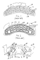
- FIG. 1 is a top view of a prior art backing plate with a metal mesh attachment structure cut to fit the backing plate welded in place thereon.
- FIG. 2 is a top view of a prior art backing plate showing a stamped form attachment structure cut to fit the backing plate welded in place thereon.
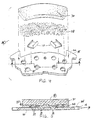
- FIG. 3 is a top plan view of a brake pad assembly embodying the invention with the friction material partially cut away to reveal the metal channel member attachment structures spot welded to the face of a backing plate.
- FIG. 4 is an exploded view of the brake pad assembly of FIG. 3 illustrating one embodiment of a method for making the assembly with a combination of preformed and loose-fill friction material.
- FIG. 5 is a cross-sectional, side elevation view of the brake pad assembly of FIG. 3 taken along line 5--5 of FIG. 4 showing the final molded position of the side walls of the channel members and the relative amounts of loose-fill and preform material which compose the final assembly.
- FIG. 6 is an exploded view of the brake pad assembly of FIG. 3 illustrating another embodiment of the method for making the assembly with only preformed friction material.
- FIG. 7 is a cross-sectional, side elevation view of the brake pad assembly of FIG. 3 taken along line 7--7 of FIG. 6 showing the final molded position of the side walls of the channel members bent inwardly around some of the friction material.
- prior art brake pad assemblies 110, 210 for high performance applications employ metal structures such as expanded metal mesh 12 or stamped plates 14 which are normally welded (as indicated at points 17) to a backing plate 116, 216.
- High volume production of prior art assemblies 110, 210 requires a tool, die and/or stamp (not shown) for cutting and or stamping the metal structure so that its outline 111, 211 substantially matches a peripheral shape 113, 213 and the surface area of backing plate 116, 216.
- Mesh 12 and plate 14 both include holes or hollow regions 15 so that pad material can be molded in and around mesh 12 and plate 14 to mechanically attach a pad to the backing plate 116, 216.
- the tool, die and/or stamp is often also used to create holes 15.
- Welding prior art attachment structures 12, 14 requires careful registration of weld points 17 so as to avoid holes 15.
- the necessary careful alignment of weld points further increases the time and expense of manufacturing prior art assemblies 110, 210.
- the time and cost of creating tools/dies/stamps and registering/aligning weld points makes these prior art systems cost prohibitive for low volume production.
- Another disadvantage is that these prior art assemblies are not capable of rapid turn around times since each different size or shape of backing plate will require new tooling and weld position programming.
- a brake pad assembly 10,10' embodying the invention provides a high-performance mechanical lock of friction material 18 to backing plate 16,16' suitable for high performance applications at low cost and with short lead times for any size or shape of backing plate.
- Assembly 10 is manufactured without a tool/die/stamp and without need to register/align weld points so they miss holes in the attachment structure.
- Brake pad assembly 10, 10' comprises friction material 18 disposed over a backing plate 16,16' to which metal channel members 20 have been attached by spot welding at points 17.
- Each channel member includes a base 22 and two side walls 24 extending from base 22.
- the surface area of base 22 is very much smaller than the surface area of plates 16,16'.
- the metal channel members are made from approximately 2.54cm long by 1.27 to 2.54cm wide by 0.051cm thick (1 inch long by 1/2 to 1 inch wide by 0.020 inch thick) sheet metal, and when first attached to backing plate 16,16' are substantially "U”-shaped with walls 24 bent slightly inwardly.
- Side walls 24 are about 0.64cm (1/4 inch) high and the base 22 is about 1.27 to 1.91cm (1/2 to 3/4 inches) in width. It is understood that channel members having other dimensions will work equally well. The dimensions provided are those of a readily available and inexpensive source of channel members, the clips used to secure metal bands on large boxes and pallets.
- channel members Any number of such channel members can be used, however, it has been found that a minimum of 1 per 32.7 square cm (5 square inches) of pad area is suitable for high performance applications. It is understood, however, that the number of channel members necessary to retain the friction material will also depend upon the size of channel member walls 24 since it is this surface area which provides the mechanical attachment.
- channel members 20 are attached to the backing plate 16,16' by spot welds 17 which are strong yet relatively quick and inexpensive. Spot welding is particularly suited to attachment of channel members 20. Their location on backing plate 16,16' is not critical and thus alignment of the weld locations is not critical. Methods such as rivets or other connectors may be used but require a drilling step or other preparation of the backing plate in addition to the added cost of the connectors.
- the backing plate 16,16' may include through holes 19, also known as I.M. holes, to aid in the attachment of friction material 18. It is understood, however, that I.M. holes are not necessary in order to obtain the advantages of the invention. If the backing plate 16,16' does include through holes, 19, preferably the diameter d on the face 26,26' of backing plate 16.16' is less than diameter D on the back surface of the backing plate 16,16' to provide an additional mechanical locking of friction material 18 to backing plate 16,16'.
- FIG. 4 schematically depicts one embodiment 40 of a method for making brake pad assembly 10.
- a first layer 28 of loose-fill friction material and/or other suitable material such as "backing stock” material is disposed over face 26 and channel members 20.
- a second layer 30 of preformed friction material may then be disposed over the first layer 28.
- the backing plate may include through holes 19 to aid in the securement of the friction material. Layers 28 and 30 are then pressure molded into a single monolithic pad of friction material 18.
- the pressure created by the step of molding first and second layers 28, 30 of friction material onto backing plate 16 causes the side walls 26 of the channei members 20 to bend inwardly around some of the friction material, thereby locking pad 18 in place with the inner surfaces of said walls.
- a layer of adhesive (not shown) may be disposed on face 26 of the backing plate 16 to provide an additional bond. It is understood that the extent to which walls 24 bend during molding will depend upon the thickness and strength of the material from which channel members 20 are made as well as the degree to which the walls were bent inwardly prior to molding. Some bending is necessary to securely attach pad 18 and preferably at least some of this bending occurs during molding although it may be all prebend.
- FIG. 6 another embodiment 42 of a method for making brake pad assembly 10' is schematically depicted.
- Assembly 10' differs from assembly 10 only in that assembly 10' utilizes a different size and shape backing plate 16' than backing plate 16 of assembly 10, illustrating that channel members 20 may be relatively quickly, easily, inexpensively and economically used to prepare high performance brake pad assemblies in low volumes from virtually any size and shape backing plate.
- either method 46,42 may be used to make either assembly 10,10' or those having virtually any size or shape backing plate.
- a single layer 30' of preformed friction material may be disposed over face 26 and channel members 20 for molding to form a pad of friction material 18.
- Single layer preform 30' of friction material may need to be thicker than the preform 30 used in other embodiments of the method which include multiple layers of material above the backing plate 16,16'.
- Method 40 is generally preferable for use when channel members 20 are made from unusually thin material and/or when preform 30 is unusually stiff since loose fill layer 28 aids to prevent preform 30 from bending walls 26 of channel member 20 flat against base 24, and thus adds to ensure mechanical attachment of pad 18 to backing plate 16.
- method 42 may be used whenever the combination of preform 30' stiffness and channel member arm 26 strength is such that the channel member arms can punch into preform 30' without bending flat prior to molding -- whether arms 24 are bent slightly inward or not.
Landscapes
- Engineering & Computer Science (AREA)
- Mechanical Engineering (AREA)
- General Engineering & Computer Science (AREA)
- Braking Arrangements (AREA)
Description
- The invention relates to a mechanical attachment system for bonding a disc pad to a backing plate in a brake pad assembly, and more specifically to a mechanical attachment system for use with backing plates having a nonstandard size or shape, such as those used in race cars, where production volume is low.
- Mechanical attachment systems for bonding the disc pad to the backing plate in brake pad assemblies are known in the art. Many prior art systems employ such automated operations as punching, drilling, die cutting and stamping to create a mechanical bond. All of these automated methods utilize dies or machining configurations which are dependent upon the size and shape of the backing plate to which the disc pad is to be bonded and, therefore, require extensive lead time and retooling each time a new size or shape backing plate is used. Other prior art systems employ methods such as brazing or sintering, operations which are costly in themselves and often require heat treating of the backing plate. The expenditure of time and capital in all of the prior art methods can be justified only when production volume is high and relatively long lead times are available.
- U.S. Pat. No. 1,225,555 discloses a system for fastening web brake shoes to brake shoe heads. A number of metallic fasteners are bolted to the brake shoe heads. These fasteners each contain several prongs which are bent slightly outward. The prongs are forced into the web brake shoe which causes the prongs to spread, thereby securing the brake shoe. A disadvantage of this prior art system is that the fasteners used to hold the brake shoe in place are relatively complicated and must be machined before this system can be used. Another disadvantage of this system is that each fastener must be individually bolted to the brake shoe heads. a relatively time consuming process. A further disadvantage is that this fastening method was designed specifically for use with a web style brake shoe and may not be compatible with modern friction materials.
- U.S. Pat. Nos. 1,336,752, 4,569,424 and 5,141,083 disclose systems for fastening friction material to the backing plate by punching or drilling holes in the backing plate to create protrusions on the face of the plate. In the '752 patent holes are punched in a thin metal plate causing prongs to penetrate into the preformed brake lining, thereby securing the lining to the plate. The '424 patent is similar; the difference being that perforations which form protruding tabs are punched before the friction material is cast directly onto the liner plate. In the '083 patent holes are drilled through the backing plate and flared flanges are created before the friction material is molded onto the backing plate. A disadvantage of these systems is the capital cost. In the above fastening methods a new die must be created each time a new size or shape backing plate is used, thereby greatly increasing preparation expenses.
- U.S. Pat. No. 4,799,579 discloses a bonding system in which metal particles (e.g., chips, shavings, kinked or bent wire sections, deformed brush-like metal bristles, corrugated hardware cloth, or metal fibers) are brazed to the backing plate before the friction material is molded onto it. A disadvantage of this method is that brazing the metal particles to the backing plate may have adverse effects on the plate itself. The steel backing plate may become softened and/or lose its flatness during the process, thus requiring the additional expense of heat-treating and/or restraightening the backing plate.
- U.S. Pat. No. 5.358.684 discloses a system for bonding friction material to the backing plate whereby a mounting bed is sinter-fused onto the backing plate before friction material is molded onto it. The mounting bed consists of a series of individually shaped members (e.g., cylinders, cones, pyramids) created in a graphite mold. A disadvantage of this method is that the graphite molds used to create the mounting bed must necessarily vary with the size and shape of the backing plate. A new mold must be created each time a backing plate with a different size or shape is to be used. Another disadvantage of this method is that sintering is expensive, time consuming, and can soften the steel backing plate, thus requiring heat-treating of the plate.
- U.S. Pat. Nos. 5,123,514 and 5,355,986 disclose another attachment system for brake assemblies. In both patents, a lamina (sometimes called a carrier) is produced by stamping from sheet metal a shape corresponding to the shape of the backing plate. Holes are then punched in a gridlike configuration, the edges of each being flanged upward so that they may be embedded into the friction material, and the lamina is attached to the backing plate. A disadvantage of this prior art is the capital cost. Since the size and shape of the lamina corresponds to the individual backing plate being used, a new stamp die must be created for each size and shape backing plate.
- U.S. Pat. Nos. 4,924,583 and 4,991,697 disclose a system for attaching friction material to the backing plate in a disc brake assembly using expanded metal mesh as a bonding reinforcement. This type of prior art involves precutting a template and then stamping a form from a sheet of mesh to the approximate size and shape of the backing plate. The stamped form is then attached to the backing plate using a spot welder. A disadvantage of this attachment method is that a new template must be produced to correspond with each backing plate. Another disadvantage of this method is that the mesh intersections and welder heads must match precisely. Both of these disadvantages lead to extremely high tooling costs. A further disadvantage of this method is that the metal mesh comprises a large portion of the disc pad surface area and thus reduces the useful life of the pad.
- What is desired, therefore, is a mechanical attachment system for bonding friction material to the backing plate in brake pad assemblies which requires short lead times and preparation expenses and which can be easily and economically adapted to backing plates of nonstandard sizes and shapes.
- According to one aspect of the invention, there is provided a brake pad assembly as defined in
claim 1. - In one embodiment of a mechanical attachment system for mounting a disc pad to a steel backing plate in brake pad assemblies, the attachment system comprises a plurality of metal channel members having a base and arm extending from the base, the members being attached to a nonstandard steel backing plate, the arms being bent inwardly during the molding of friction material to the backing plate, to mechanically lock the molded friction material in place on the backing plate.
- Preferably, the channel members are metal "U"-shaped forms which are standard in size and shape, with one size being used for any size disc pad, thus requiring no added tooling costs. The upright legs of the metal forms preferably bend slightly inward during molding, thereby locking the friction material securely to the backing plate. Preferably, each channel member is attached by spot welding to the backing plate, for example in two places on its base. Adhesive bonding is preferably used in addition to the mechanical attachment method described herein in order to reinforce the bonding.
- The system may use channel members made of soft metal which mechanically lock the disc pad in place, while comprising a small portion of the total disc pad surface area.
- The system may be used with both preform and loose fill methods of molding disc pads.
- Assemblies embodying the invention provide a mechanical attachment system to bond a disc pad to a steel backing plate in brake pad assemblies, which system is capable of being quickly and easily adapted to differently sized and shaped brake pad assemblies at low cost. The system allows for the economical manufacture of short production runs of brake pad assemblies.
- According to another aspect, the invention provides a method for making a brake pad assembly as defined in claim 6.
- In one embodiment, a method of mechanically attaching a disc pad to a backing plate in brake pad assemblies comprises the steps of providing a backing plate having a nonstandard size or shape, spot welding a plurality of metal forms on a face of the backing plate, molding friction material onto the face of the backing plate which contains the metal forms, and bending arm members extending from the base of the metal forms with the molding pressure to mechanically lock the molded friction material in place on the backing plate.
- Reference will now be made to the accompanying drawings, in which:-
- FIG. 1 is a top view of a prior art backing plate with a metal mesh attachment structure cut to fit the backing plate welded in place thereon.
- FIG. 2 is a top view of a prior art backing plate showing a stamped form attachment structure cut to fit the backing plate welded in place thereon.
- FIG. 3 is a top plan view of a brake pad assembly embodying the invention with the friction material partially cut away to reveal the metal channel member attachment structures spot welded to the face of a backing plate.
- FIG. 4 is an exploded view of the brake pad assembly of FIG. 3 illustrating one embodiment of a method for making the assembly with a combination of preformed and loose-fill friction material.
- FIG. 5 is a cross-sectional, side elevation view of the brake pad assembly of FIG. 3 taken along line 5--5 of FIG. 4 showing the final molded position of the side walls of the channel members and the relative amounts of loose-fill and preform material which compose the final assembly.
- FIG. 6 is an exploded view of the brake pad assembly of FIG. 3 illustrating another embodiment of the method for making the assembly with only preformed friction material.
- FIG. 7 is a cross-sectional, side elevation view of the brake pad assembly of FIG. 3 taken along line 7--7 of FIG. 6 showing the final molded position of the side walls of the channel members bent inwardly around some of the friction material.
- Referring to FIGS. 1 and 2, prior art
brake pad assemblies 110, 210 for high performance applications employ metal structures such as expandedmetal mesh 12 or stampedplates 14 which are normally welded (as indicated at points 17) to abacking plate prior art assemblies 110, 210 requires a tool, die and/or stamp (not shown) for cutting and or stamping the metal structure so that itsoutline 111, 211 substantially matches aperipheral shape backing plate Mesh 12 andplate 14 both include holes orhollow regions 15 so that pad material can be molded in and aroundmesh 12 andplate 14 to mechanically attach a pad to thebacking plate plate 14 the tool, die and/or stamp is often also used to createholes 15. - Welding prior
art attachment structures holes 15. The necessary careful alignment of weld points further increases the time and expense of manufacturingprior art assemblies 110, 210. The time and cost of creating tools/dies/stamps and registering/aligning weld points makes these prior art systems cost prohibitive for low volume production. Another disadvantage is that these prior art assemblies are not capable of rapid turn around times since each different size or shape of backing plate will require new tooling and weld position programming. - Referring to FIGS. 3-7, a
brake pad assembly 10,10' embodying the invention provides a high-performance mechanical lock offriction material 18 tobacking plate 16,16' suitable for high performance applications at low cost and with short lead times for any size or shape of backing plate.Assembly 10 is manufactured without a tool/die/stamp and without need to register/align weld points so they miss holes in the attachment structure. -
Brake pad assembly 10, 10' comprisesfriction material 18 disposed over abacking plate 16,16' to whichmetal channel members 20 have been attached by spot welding at points 17. Each channel member includes abase 22 and twoside walls 24 extending frombase 22. The surface area ofbase 22 is very much smaller than the surface area ofplates 16,16'. The metal channel members are made from approximately 2.54cm long by 1.27 to 2.54cm wide by 0.051cm thick (1 inch long by 1/2 to 1 inch wide by 0.020 inch thick) sheet metal, and when first attached to backingplate 16,16' are substantially "U"-shaped withwalls 24 bent slightly inwardly.Side walls 24 are about 0.64cm (1/4 inch) high and thebase 22 is about 1.27 to 1.91cm (1/2 to 3/4 inches) in width. It is understood that channel members having other dimensions will work equally well. The dimensions provided are those of a readily available and inexpensive source of channel members, the clips used to secure metal bands on large boxes and pallets. - Any number of such channel members can be used, however, it has been found that a minimum of 1 per 32.7 square cm (5 square inches) of pad area is suitable for high performance applications. It is understood, however, that the number of channel members necessary to retain the friction material will also depend upon the size of
channel member walls 24 since it is this surface area which provides the mechanical attachment. - Although other methods are possible,
channel members 20 are attached to thebacking plate 16,16' byspot welds 17 which are strong yet relatively quick and inexpensive. Spot welding is particularly suited to attachment ofchannel members 20. Their location on backingplate 16,16' is not critical and thus alignment of the weld locations is not critical. Methods such as rivets or other connectors may be used but require a drilling step or other preparation of the backing plate in addition to the added cost of the connectors. - As shown in FIG. 3, the
backing plate 16,16' may include throughholes 19, also known as I.M. holes, to aid in the attachment offriction material 18. It is understood, however, that I.M. holes are not necessary in order to obtain the advantages of the invention. If thebacking plate 16,16' does include through holes, 19, preferably the diameter d on theface 26,26' of backing plate 16.16' is less than diameter D on the back surface of thebacking plate 16,16' to provide an additional mechanical locking offriction material 18 tobacking plate 16,16'. - In another aspect, the invention provides a method of making
brake pad assembly 10. FIG. 4 schematically depicts oneembodiment 40 of a method for makingbrake pad assembly 10. After attachment ofchannel members 20 to face 26 ofbacking plate 16, afirst layer 28 of loose-fill friction material and/or other suitable material such as "backing stock" material is disposed overface 26 andchannel members 20. Asecond layer 30 of preformed friction material may then be disposed over thefirst layer 28. As discussed above, the backing plate may include throughholes 19 to aid in the securement of the friction material.Layers friction material 18. - Referring to FIG. 5. the pressure created by the step of molding first and
second layers backing plate 16 causes theside walls 26 of thechannei members 20 to bend inwardly around some of the friction material, thereby lockingpad 18 in place with the inner surfaces of said walls. If desired. a layer of adhesive (not shown) may be disposed onface 26 of thebacking plate 16 to provide an additional bond. It is understood that the extent to whichwalls 24 bend during molding will depend upon the thickness and strength of the material from whichchannel members 20 are made as well as the degree to which the walls were bent inwardly prior to molding. Some bending is necessary to securely attachpad 18 and preferably at least some of this bending occurs during molding although it may be all prebend. - Referring now to FIG. 6 another embodiment 42 of a method for making brake pad assembly 10' is schematically depicted. Assembly 10' differs from
assembly 10 only in that assembly 10' utilizes a different size and shape backing plate 16' than backingplate 16 ofassembly 10, illustrating thatchannel members 20 may be relatively quickly, easily, inexpensively and economically used to prepare high performance brake pad assemblies in low volumes from virtually any size and shape backing plate. In this regard, it is understood that either method 46,42 may be used to make eitherassembly 10,10' or those having virtually any size or shape backing plate. - After attachment of
channel members 20 tobacking plate face 26, a single layer 30' of preformed friction material may be disposed overface 26 andchannel members 20 for molding to form a pad offriction material 18. Single layer preform 30' of friction material may need to be thicker than thepreform 30 used in other embodiments of the method which include multiple layers of material above thebacking plate 16,16'.Method 40 is generally preferable for use whenchannel members 20 are made from unusually thin material and/or whenpreform 30 is unusually stiff sinceloose fill layer 28 aids to preventpreform 30 from bendingwalls 26 ofchannel member 20 flat againstbase 24, and thus adds to ensure mechanical attachment ofpad 18 tobacking plate 16. - Conversely, method 42 may be used whenever the combination of preform 30' stiffness and
channel member arm 26 strength is such that the channel member arms can punch into preform 30' without bending flat prior to molding -- whetherarms 24 are bent slightly inward or not. - Although the invention has been described with reference to a particular arrangement of parts, features and the like, these are not intended to exhaust all possible arrangements or features, and indeed many other modifications and variations will be ascertainable to those of skill in the art.
Claims (11)
- A brake pad assembly for efficient low volume production, comprising:characterised by:a backing plate (16,16') having a plate surface area; anda brake pad (18) molded to the face (26) of said backing plate;at least one channel member (20), said channel member having a base (22) and having two side walls (24) extending from the base, the base having a surface area substantially smaller than the surface area of said backing plate;means (17) attaching said channel member (20) to said backing plate (16, 16'); andthe walls (24) of said channel member being bent inwardly to mechanically lock said brake pad to said backing plate.
- The brake pad assembly of claim 1, wherein said backing plate (16, 16') contains at least one hole (19) filled with pad material (28) to aid in securing said brake pad (18) to said backing plate.
- The brake pad assembly of claim 2, wherein said backing plate (16, 16') further comprises a back surface, and wherein said hole (19) further comprises a first diameter on said face (26) of said backing plate which is less than a second diameter on said back surface of said backing plate to aid in securing said brake pad to said backing plate.
- The brake pad assembly of claim 1, 2 or 3, further comprising a layer of adhesive between said backing plate (16, 16') and said brake pad (18) to reinforce the mechanical attachment produced by said channel members (20).
- The brake pad assembly of any preceding claim, wherein said channel members (20) are preformed banding clips.
- A method for making a brake pad assembly comprising the steps of:providing a first nonstandard backing plate (16, 16');providing at least one metal channel member (20) having a base (22) and two side walls (24) extending from said base;attaching the channel member base (22) to the first backing plate (16, 16');molding friction material into a monolithic pad (18); andbending the side walls (24) of the at least one channel member slightly inward during molding, and/or prior to molding, to mechanically attach the pad to the first backing plate.
- The method of claim 6, including the additional steps of:providing a second nonstandard backing plate (16, 16') different than the first nonstandard backing plate;attaching a channel member (20) onto the second nonstandard backing plate;molding friction material into a second monolithic pad (18); andbending the side walls (24) of the second channel member (20) slightly inward during molding, and/or prior to molding, to mechanically attach the second pad to the second backing plate, whereby low volume production runs of nonstandard brake pad assemblies may be manufactured relatively quickly and economically.
- The method of claim 6 or 7, including the step of applying adhesive to the first nonstandard backing plate prior to molding.
- The method of claim 6, 7 or 8, including, before molding, the steps of providing a friction material preform (30, 30') and pressing the preform onto the channel member arms.
- The method of claim 9 including, before pressing, the step of adding loose fill friction material (28) between the first nonstandard backing plate and preform.
- The assembly of any of claims 1 to 5, or method of any of claims 6 to 10, wherein the or each channel member (20) is attached to the backing plate (16, 16') by welding, for example spot welding, such as manual spot welding.
Applications Claiming Priority (2)
| Application Number | Priority Date | Filing Date | Title |
|---|---|---|---|
| US56137595A | 1995-11-21 | 1995-11-21 | |
| US561375 | 1995-11-21 |
Publications (2)
| Publication Number | Publication Date |
|---|---|
| EP0775842A1 EP0775842A1 (en) | 1997-05-28 |
| EP0775842B1 true EP0775842B1 (en) | 2000-10-04 |
Family
ID=24241685
Family Applications (1)
| Application Number | Title | Priority Date | Filing Date |
|---|---|---|---|
| EP96305698A Expired - Lifetime EP0775842B1 (en) | 1995-11-21 | 1996-08-01 | Mechanical attachment system and method for low volume production of brake pad assemblies |
Country Status (4)
| Country | Link |
|---|---|
| US (1) | US5732800A (en) |
| EP (1) | EP0775842B1 (en) |
| CA (1) | CA2183115C (en) |
| DE (1) | DE69610546T2 (en) |
Families Citing this family (32)
| Publication number | Priority date | Publication date | Assignee | Title |
|---|---|---|---|---|
| GB9515926D0 (en) * | 1995-08-03 | 1995-10-04 | T & N Technology Ltd | Manufacture of brake pads |
| DE19627440C2 (en) * | 1996-07-08 | 2000-01-05 | Reinhard Mowka | Process for the production of disc brake pads |
| AUPO426296A0 (en) * | 1996-12-18 | 1997-01-23 | Hi-Bond Research Pty Ltd | Friction lining attachments |
| US5875873A (en) * | 1997-05-05 | 1999-03-02 | Meritor Heavy Vehicle Systems, Llc | Air disc brake anti-rattle design |
| US6405840B1 (en) * | 1999-11-19 | 2002-06-18 | Meritor Heavy Vehicle Systems, Llc | Rigid panel attachment for brake linings |
| DE10034210A1 (en) * | 2000-07-13 | 2002-01-24 | Tmd Friction Gmbh | Brake shoe and method for producing a brake shoe |
| US7320386B2 (en) * | 2003-01-03 | 2008-01-22 | Federal Mogul World Wide, Inc. | High friction brake shoe assembly |
| US6860368B2 (en) * | 2003-01-03 | 2005-03-01 | Federal-Mogul World Wide, Inc. | High friction brake shoe assembly |
| US9700450B2 (en) * | 2003-07-28 | 2017-07-11 | Baronova, Inc. | Devices and methods for gastrointestinal stimulation |
| US20050161297A1 (en) * | 2004-01-23 | 2005-07-28 | Innovative Technologies, Llc | Brake pad backing plate and method of making the same |
| DE102005028796B4 (en) * | 2005-06-22 | 2010-07-01 | Tmd Friction Gmbh | Pad carrier for a disc brake |
| DE102007017785B3 (en) * | 2007-04-16 | 2008-11-06 | Federal-Mogul Friction Products Gmbh | Brake pad with a back plate with increased rigidity |
| CA132914S (en) | 2009-11-12 | 2010-06-22 | Ray Arbesman | Replaceable friction element for a brake pad assembly |
| CA132912S (en) | 2009-11-12 | 2010-06-22 | Ray Arbesman | Replaceable friction element for a brake pad assembly |
| CA132913S (en) | 2009-11-12 | 2010-06-22 | Ray Arbesman | Brake pad assembly with replaceable friction elements |
| CA2725910A1 (en) * | 2010-12-16 | 2012-06-16 | Anstro Manufacturing, Inc. | Brake pad assembly with embedded shim |
| US8974725B2 (en) | 2011-09-29 | 2015-03-10 | Federal-Mogul Products, Inc. | Friction material tooling |
| DE102011118127B4 (en) * | 2011-11-10 | 2015-04-02 | Knorr-Bremse Systeme für Nutzfahrzeuge GmbH | Brake pad for a disc brake |
| CA3040130C (en) | 2012-06-18 | 2021-09-14 | Gripmetal Limited | Process for making a laminated sheet |
| DE102013222760A1 (en) * | 2012-11-27 | 2014-05-28 | Schaeffler Technologies Gmbh & Co. Kg | Friction plate with mechanically connected friction material |
| BR102013031407B1 (en) * | 2013-12-06 | 2020-09-01 | Fras-Le S/A | BRAKE PAD PLATE FOR A DISC BRAKE |
| US9950495B2 (en) | 2014-07-24 | 2018-04-24 | Nugripmetal S.A.R.L. | System and method for additive manufacturing of a three-dimensional object |
| US9360067B1 (en) | 2015-02-05 | 2016-06-07 | R. A. Investment Management S.A.R.L. | Hybrid laminate |
| US9388872B1 (en) * | 2015-03-26 | 2016-07-12 | Nucap Industries Inc. | Friction fusion fastening system |
| US10125836B2 (en) * | 2015-06-10 | 2018-11-13 | Nucap Industries Inc. | Brake pad with preformed multi-layer friction pad and shim |
| US9982730B2 (en) * | 2016-06-21 | 2018-05-29 | Nissan North America, Inc. | Brake pad |
| US9982729B2 (en) * | 2016-06-21 | 2018-05-29 | Nissan North America, Inc. | Brake pad |
| US10315382B2 (en) | 2016-12-22 | 2019-06-11 | Gripmetal Limited | Process for manufacturing textured laminate sheet |
| US11060503B2 (en) * | 2018-03-13 | 2021-07-13 | Wind Solutions, Llc | Yaw pad engagement features |
| US12264715B2 (en) | 2018-10-12 | 2025-04-01 | Federal-Mogul Motorparts Llc | Brake pad backing plate |
| CN117366140A (en) | 2019-06-11 | 2024-01-09 | Rfpc控股公司 | Friction device with integrated insert |
| DE102022204974A1 (en) | 2022-05-18 | 2023-11-23 | Hl Mando Corporation | Brake block for a disc brake system and disc brake system |
Family Cites Families (7)
| Publication number | Priority date | Publication date | Assignee | Title |
|---|---|---|---|---|
| US1225555A (en) * | 1916-07-13 | 1917-05-08 | William Achtmeyer | Web-fastener. |
| US3343770A (en) * | 1965-07-26 | 1967-09-26 | Cellasto Inc | Bonding of an elastic shock absorber with a rigid base plate |
| JPS55155935A (en) * | 1979-05-22 | 1980-12-04 | Sumitomo Electric Ind Ltd | Pad for disc brake |
| JPS5663136A (en) * | 1979-10-23 | 1981-05-29 | Sumitomo Electric Ind Ltd | Friction pad assembly |
| GB2123908B (en) * | 1982-07-14 | 1986-04-23 | Automotive Products Plc | Disc brake pad |
| JPH03255235A (en) * | 1990-03-05 | 1991-11-14 | Hitachi Chem Co Ltd | Clutch driven plate |
| US5123514A (en) * | 1991-09-20 | 1992-06-23 | Echlin Inc. | Clutch or brake system for a heavy duty vehicle |
-
1996
- 1996-08-01 EP EP96305698A patent/EP0775842B1/en not_active Expired - Lifetime
- 1996-08-01 DE DE69610546T patent/DE69610546T2/en not_active Expired - Fee Related
- 1996-08-12 CA CA002183115A patent/CA2183115C/en not_active Expired - Fee Related
-
1997
- 1997-05-09 US US08/854,114 patent/US5732800A/en not_active Expired - Fee Related
Also Published As
| Publication number | Publication date |
|---|---|
| CA2183115A1 (en) | 1997-05-22 |
| DE69610546T2 (en) | 2001-05-31 |
| EP0775842A1 (en) | 1997-05-28 |
| CA2183115C (en) | 2006-05-16 |
| US5732800A (en) | 1998-03-31 |
| DE69610546D1 (en) | 2000-11-09 |
Similar Documents
| Publication | Publication Date | Title |
|---|---|---|
| US5732800A (en) | Mechanical attachment system for low volume production of brake pad assemblies | |
| EP1155246B1 (en) | Brake plate and method and apparatus for manufacturing same | |
| US10316911B2 (en) | Composite disc brake backing plate | |
| US4770283A (en) | Friction ring for clutches or brakes, and a method and device for producing the friction ring | |
| CA2240227A1 (en) | Disc brake backing plate and method of manufacturing same | |
| JPS6228441A (en) | Grasping rod of non-protective loom | |
| US7731004B2 (en) | Brake lining with damper plate | |
| JP2008517230A5 (en) | ||
| US20020071933A1 (en) | Flanged honeycomb core and method of making same | |
| US6122951A (en) | Method of manufacturing a disc brake plate with an edge hole | |
| CN112805486B (en) | Backing plate for brake pad | |
| EP0180389B1 (en) | Friction components for clutch plates and the like | |
| JPS62209235A (en) | Manufacture of disc brake pad | |
| JP4527010B2 (en) | Brake shoe manufacturing method | |
| JP3208287B2 (en) | Brake pad for disc brake and method of manufacturing the same | |
| EP0295910A1 (en) | Integrated cutting blade assembly | |
| JPH05285972A (en) | Impregnated laminate pressing method | |
| JPH01158236A (en) | Brake-shoe-rib and method of molding plurality of brake-shoe-rib | |
| JPH0742829Y2 (en) | Holder mounting structure for automobile lining base material | |
| EP0503840A1 (en) | Chain saw guide bar | |
| JPS6234975B2 (en) | ||
| JPS608943B2 (en) | Core material panel | |
| JPS5821709Y2 (en) | composite board | |
| JPS6328696B2 (en) | ||
| JPS60181455A (en) | Sandwich panel |
Legal Events
| Date | Code | Title | Description |
|---|---|---|---|
| PUAI | Public reference made under article 153(3) epc to a published international application that has entered the european phase |
Free format text: ORIGINAL CODE: 0009012 |
|
| AK | Designated contracting states |
Kind code of ref document: A1 Designated state(s): DE FR GB IT |
|
| 17P | Request for examination filed |
Effective date: 19971107 |
|
| 17Q | First examination report despatched |
Effective date: 19990512 |
|
| GRAG | Despatch of communication of intention to grant |
Free format text: ORIGINAL CODE: EPIDOS AGRA |
|
| GRAG | Despatch of communication of intention to grant |
Free format text: ORIGINAL CODE: EPIDOS AGRA |
|
| GRAH | Despatch of communication of intention to grant a patent |
Free format text: ORIGINAL CODE: EPIDOS IGRA |
|
| GRAH | Despatch of communication of intention to grant a patent |
Free format text: ORIGINAL CODE: EPIDOS IGRA |
|
| RAP1 | Party data changed (applicant data changed or rights of an application transferred) |
Owner name: HALDEX BRAKE CORPORATION |
|
| GRAA | (expected) grant |
Free format text: ORIGINAL CODE: 0009210 |
|
| AK | Designated contracting states |
Kind code of ref document: B1 Designated state(s): DE FR GB IT |
|
| REF | Corresponds to: |
Ref document number: 69610546 Country of ref document: DE Date of ref document: 20001109 |
|
| ET | Fr: translation filed | ||
| ITF | It: translation for a ep patent filed | ||
| PLBE | No opposition filed within time limit |
Free format text: ORIGINAL CODE: 0009261 |
|
| STAA | Information on the status of an ep patent application or granted ep patent |
Free format text: STATUS: NO OPPOSITION FILED WITHIN TIME LIMIT |
|
| 26N | No opposition filed | ||
| REG | Reference to a national code |
Ref country code: GB Ref legal event code: IF02 |
|
| PGFP | Annual fee paid to national office [announced via postgrant information from national office to epo] |
Ref country code: FR Payment date: 20050718 Year of fee payment: 10 |
|
| PGFP | Annual fee paid to national office [announced via postgrant information from national office to epo] |
Ref country code: GB Payment date: 20050728 Year of fee payment: 10 |
|
| PGFP | Annual fee paid to national office [announced via postgrant information from national office to epo] |
Ref country code: DE Payment date: 20050831 Year of fee payment: 10 |
|
| PGFP | Annual fee paid to national office [announced via postgrant information from national office to epo] |
Ref country code: IT Payment date: 20060831 Year of fee payment: 11 |
|
| PG25 | Lapsed in a contracting state [announced via postgrant information from national office to epo] |
Ref country code: DE Free format text: LAPSE BECAUSE OF NON-PAYMENT OF DUE FEES Effective date: 20070301 |
|
| GBPC | Gb: european patent ceased through non-payment of renewal fee |
Effective date: 20060801 |
|
| REG | Reference to a national code |
Ref country code: FR Ref legal event code: ST Effective date: 20070430 |
|
| PG25 | Lapsed in a contracting state [announced via postgrant information from national office to epo] |
Ref country code: GB Free format text: LAPSE BECAUSE OF NON-PAYMENT OF DUE FEES Effective date: 20060801 |
|
| PG25 | Lapsed in a contracting state [announced via postgrant information from national office to epo] |
Ref country code: FR Free format text: LAPSE BECAUSE OF NON-PAYMENT OF DUE FEES Effective date: 20060831 |
|
| PG25 | Lapsed in a contracting state [announced via postgrant information from national office to epo] |
Ref country code: IT Free format text: LAPSE BECAUSE OF NON-PAYMENT OF DUE FEES Effective date: 20070801 |