EP0775808B1 - Process for manufacturing the body of a catalyst for the catalytic treatment of gases, catalytic body and catalyst - Google Patents
Process for manufacturing the body of a catalyst for the catalytic treatment of gases, catalytic body and catalyst Download PDFInfo
- Publication number
- EP0775808B1 EP0775808B1 EP96810775A EP96810775A EP0775808B1 EP 0775808 B1 EP0775808 B1 EP 0775808B1 EP 96810775 A EP96810775 A EP 96810775A EP 96810775 A EP96810775 A EP 96810775A EP 0775808 B1 EP0775808 B1 EP 0775808B1
- Authority
- EP
- European Patent Office
- Prior art keywords
- sheet metal
- walls
- metal members
- wall
- edges
- Prior art date
- Legal status (The legal status is an assumption and is not a legal conclusion. Google has not performed a legal analysis and makes no representation as to the accuracy of the status listed.)
- Expired - Lifetime
Links
- 239000003054 catalyst Substances 0.000 title claims description 140
- 238000000034 method Methods 0.000 title claims description 28
- 230000003197 catalytic effect Effects 0.000 title claims description 22
- 238000004519 manufacturing process Methods 0.000 title claims description 19
- 239000007789 gas Substances 0.000 title description 31
- 229910052751 metal Inorganic materials 0.000 claims description 175
- 239000002184 metal Substances 0.000 claims description 51
- 238000000576 coating method Methods 0.000 claims description 45
- 239000000463 material Substances 0.000 claims description 22
- 238000003466 welding Methods 0.000 claims description 16
- 239000007769 metal material Substances 0.000 claims description 12
- 239000011149 active material Substances 0.000 claims description 9
- 238000002485 combustion reaction Methods 0.000 claims description 6
- 230000008018 melting Effects 0.000 claims description 3
- 238000002844 melting Methods 0.000 claims description 3
- 239000011148 porous material Substances 0.000 claims description 3
- 238000000746 purification Methods 0.000 claims description 3
- 239000000758 substrate Substances 0.000 claims description 3
- 229910000510 noble metal Inorganic materials 0.000 claims description 2
- 230000004927 fusion Effects 0.000 claims 2
- XEEYBQQBJWHFJM-UHFFFAOYSA-N Iron Chemical compound [Fe] XEEYBQQBJWHFJM-UHFFFAOYSA-N 0.000 description 8
- 239000011248 coating agent Substances 0.000 description 7
- 239000000945 filler Substances 0.000 description 6
- 125000006850 spacer group Chemical group 0.000 description 6
- 229910052742 iron Inorganic materials 0.000 description 4
- BASFCYQUMIYNBI-UHFFFAOYSA-N platinum Chemical compound [Pt] BASFCYQUMIYNBI-UHFFFAOYSA-N 0.000 description 4
- 239000010970 precious metal Substances 0.000 description 4
- 230000000694 effects Effects 0.000 description 3
- 239000007921 spray Substances 0.000 description 3
- 230000007704 transition Effects 0.000 description 3
- CURLTUGMZLYLDI-UHFFFAOYSA-N Carbon dioxide Chemical compound O=C=O CURLTUGMZLYLDI-UHFFFAOYSA-N 0.000 description 2
- 229910000831 Steel Inorganic materials 0.000 description 2
- 230000001133 acceleration Effects 0.000 description 2
- 238000004140 cleaning Methods 0.000 description 2
- 238000005520 cutting process Methods 0.000 description 2
- 230000007423 decrease Effects 0.000 description 2
- 239000007788 liquid Substances 0.000 description 2
- 239000000203 mixture Substances 0.000 description 2
- 229910052697 platinum Inorganic materials 0.000 description 2
- 229910052703 rhodium Inorganic materials 0.000 description 2
- 239000010948 rhodium Substances 0.000 description 2
- MHOVAHRLVXNVSD-UHFFFAOYSA-N rhodium atom Chemical compound [Rh] MHOVAHRLVXNVSD-UHFFFAOYSA-N 0.000 description 2
- 238000005507 spraying Methods 0.000 description 2
- 239000010959 steel Substances 0.000 description 2
- 241000446313 Lamella Species 0.000 description 1
- 239000011324 bead Substances 0.000 description 1
- 238000005219 brazing Methods 0.000 description 1
- 239000001569 carbon dioxide Substances 0.000 description 1
- 229910002092 carbon dioxide Inorganic materials 0.000 description 1
- 239000000969 carrier Substances 0.000 description 1
- 239000003795 chemical substances by application Substances 0.000 description 1
- 230000003111 delayed effect Effects 0.000 description 1
- 239000006185 dispersion Substances 0.000 description 1
- 238000001035 drying Methods 0.000 description 1
- 230000002349 favourable effect Effects 0.000 description 1
- 239000011261 inert gas Substances 0.000 description 1
- 238000009434 installation Methods 0.000 description 1
- 238000003475 lamination Methods 0.000 description 1
- 230000001050 lubricating effect Effects 0.000 description 1
- 239000011159 matrix material Substances 0.000 description 1
- 229910052756 noble gas Inorganic materials 0.000 description 1
- TWNQGVIAIRXVLR-UHFFFAOYSA-N oxo(oxoalumanyloxy)alumane Chemical compound O=[Al]O[Al]=O TWNQGVIAIRXVLR-UHFFFAOYSA-N 0.000 description 1
- 230000035515 penetration Effects 0.000 description 1
- 238000012805 post-processing Methods 0.000 description 1
- 238000002360 preparation method Methods 0.000 description 1
- 238000000926 separation method Methods 0.000 description 1
- 239000007787 solid Substances 0.000 description 1
- 238000007711 solidification Methods 0.000 description 1
- 230000008023 solidification Effects 0.000 description 1
- 239000002904 solvent Substances 0.000 description 1
- 229910001220 stainless steel Inorganic materials 0.000 description 1
- 239000010935 stainless steel Substances 0.000 description 1
Images


Classifications
-
- B—PERFORMING OPERATIONS; TRANSPORTING
- B01—PHYSICAL OR CHEMICAL PROCESSES OR APPARATUS IN GENERAL
- B01J—CHEMICAL OR PHYSICAL PROCESSES, e.g. CATALYSIS OR COLLOID CHEMISTRY; THEIR RELEVANT APPARATUS
- B01J35/00—Catalysts, in general, characterised by their form or physical properties
- B01J35/50—Catalysts, in general, characterised by their form or physical properties characterised by their shape or configuration
- B01J35/56—Foraminous structures having flow-through passages or channels, e.g. grids or three-dimensional monoliths
-
- B—PERFORMING OPERATIONS; TRANSPORTING
- B01—PHYSICAL OR CHEMICAL PROCESSES OR APPARATUS IN GENERAL
- B01J—CHEMICAL OR PHYSICAL PROCESSES, e.g. CATALYSIS OR COLLOID CHEMISTRY; THEIR RELEVANT APPARATUS
- B01J37/00—Processes, in general, for preparing catalysts; Processes, in general, for activation of catalysts
- B01J37/34—Irradiation by, or application of, electric, magnetic or wave energy, e.g. ultrasonic waves ; Ionic sputtering; Flame or plasma spraying; Particle radiation
- B01J37/349—Irradiation by, or application of, electric, magnetic or wave energy, e.g. ultrasonic waves ; Ionic sputtering; Flame or plasma spraying; Particle radiation making use of flames, plasmas or lasers
-
- F—MECHANICAL ENGINEERING; LIGHTING; HEATING; WEAPONS; BLASTING
- F01—MACHINES OR ENGINES IN GENERAL; ENGINE PLANTS IN GENERAL; STEAM ENGINES
- F01N—GAS-FLOW SILENCERS OR EXHAUST APPARATUS FOR MACHINES OR ENGINES IN GENERAL; GAS-FLOW SILENCERS OR EXHAUST APPARATUS FOR INTERNAL COMBUSTION ENGINES
- F01N13/00—Exhaust or silencing apparatus characterised by constructional features ; Exhaust or silencing apparatus, or parts thereof, having pertinent characteristics not provided for in, or of interest apart from, groups F01N1/00 - F01N5/00, F01N9/00, F01N11/00
- F01N13/011—Exhaust or silencing apparatus characterised by constructional features ; Exhaust or silencing apparatus, or parts thereof, having pertinent characteristics not provided for in, or of interest apart from, groups F01N1/00 - F01N5/00, F01N9/00, F01N11/00 having two or more purifying devices arranged in parallel
- F01N13/017—Exhaust or silencing apparatus characterised by constructional features ; Exhaust or silencing apparatus, or parts thereof, having pertinent characteristics not provided for in, or of interest apart from, groups F01N1/00 - F01N5/00, F01N9/00, F01N11/00 having two or more purifying devices arranged in parallel the purifying devices are arranged in a single housing
-
- F—MECHANICAL ENGINEERING; LIGHTING; HEATING; WEAPONS; BLASTING
- F01—MACHINES OR ENGINES IN GENERAL; ENGINE PLANTS IN GENERAL; STEAM ENGINES
- F01N—GAS-FLOW SILENCERS OR EXHAUST APPARATUS FOR MACHINES OR ENGINES IN GENERAL; GAS-FLOW SILENCERS OR EXHAUST APPARATUS FOR INTERNAL COMBUSTION ENGINES
- F01N3/00—Exhaust or silencing apparatus having means for purifying, rendering innocuous, or otherwise treating exhaust
- F01N3/08—Exhaust or silencing apparatus having means for purifying, rendering innocuous, or otherwise treating exhaust for rendering innocuous
- F01N3/10—Exhaust or silencing apparatus having means for purifying, rendering innocuous, or otherwise treating exhaust for rendering innocuous by thermal or catalytic conversion of noxious components of exhaust
- F01N3/24—Exhaust or silencing apparatus having means for purifying, rendering innocuous, or otherwise treating exhaust for rendering innocuous by thermal or catalytic conversion of noxious components of exhaust characterised by constructional aspects of converting apparatus
- F01N3/28—Construction of catalytic reactors
- F01N3/2803—Construction of catalytic reactors characterised by structure, by material or by manufacturing of catalyst support
- F01N3/2807—Metal other than sintered metal
- F01N3/281—Metallic honeycomb monoliths made of stacked or rolled sheets, foils or plates
-
- F—MECHANICAL ENGINEERING; LIGHTING; HEATING; WEAPONS; BLASTING
- F01—MACHINES OR ENGINES IN GENERAL; ENGINE PLANTS IN GENERAL; STEAM ENGINES
- F01N—GAS-FLOW SILENCERS OR EXHAUST APPARATUS FOR MACHINES OR ENGINES IN GENERAL; GAS-FLOW SILENCERS OR EXHAUST APPARATUS FOR INTERNAL COMBUSTION ENGINES
- F01N2450/00—Methods or apparatus for fitting, inserting or repairing different elements
- F01N2450/22—Methods or apparatus for fitting, inserting or repairing different elements by welding or brazing
Definitions
- the invention relates to a method for producing a Catalyst body for the catalytic treatment of gas, especially for the catalytic purification of exhaust gas Internal combustion engine.
- a Catalyst body for the catalytic treatment of gas especially for the catalytic purification of exhaust gas
- Internal combustion engine Such for installation in a housing Catalyst bodies provided for catalyst are often also referred to as the substrate.
- the internal combustion engine can Example of an automobile or other motor vehicle belong or be arranged stationary.
- a catalyst known from US-A 5 187 142 has a catalyst body with stacked, quadrangular corrugated iron elements, each in one Herringbone pattern has arranged waves. Between successive groups of such corrugated iron elements Bracket elements arranged, each one square, corrugated main section and at two mutually facing edges of this one angled Owns rag.
- In the manufacture of such Catalyst body are first bare corrugated iron elements and Bracket elements made and stacked on top of each other. Then the sheet metal elements through at their points of contact Brazing or discharge welding joined together and the overlapping lobes with each other and possibly also welded to the corrugated iron elements, so that a package of firmly connected Sheet metal elements are created, the lobes together inside and Form external surfaces with steps. After that, coatings are made with catalytically active material on the interconnected Sheet metal elements applied. The sheet metal elements then limit together passages for the exhaust gas.
- the catalyst body therefore has a cross to the general Exhaust gas flow direction cross section only a small number of passes per cross-sectional area unit, the opposing sections of the Surfaces of a passage generally have large gaps from each other.
- the catalyst body results from these Reasons only a low cleaning effect per unit volume of the catalyst body and must therefore be possible to enable a sufficient exhaust gas purification are relatively large.
- the known catalyst body and one with such equipped catalyst therefore have the disadvantages that they take up a lot of space and are correspondingly heavy.
- the size Mass of the known catalyst body also increases a cold start the time to heat up the catalyst body to a temperature that is favorable for effective exhaust gas cleaning.
- the catalyst bodies contain expensive materials, especially usually at least one in the coatings existing precious metal, so that the large mass of a known catalyst body also the manufacturing cost of Catalyst increased.
- JP-A 6 254 409 for Manufacturing a catalyst body will be flat and corrugated Sheet metal elements inserted in two sleeves and in these attached. Then the two sleeves together welded. After that, coatings with a catalytic active material applied to the sheet metal elements.
- the waves the corrugated sheet metal elements of a manufactured in this way Catalyst body must also have large wave heights, so that after assembling the sheet metal elements Can apply coatings on this.
- That from JP-A 6 254 409 known manufacturing method and the manufactured with it Catalyst bodies therefore have largely similar disadvantages how the manufacturing process and the catalyst body according to U.S. Patent 5,187,142.
- the Lengths of the catalyst body and sheet metal elements at least 100 mm and the widths of the spacers about 5 mm.
- the Spacer elements and the bare ones covered by them Edge sections of the sheet metal elements have a relatively large Mass, the time to heat up the cold start Catalyst body to the optimal operating temperature delayed. Endurance tests with catalysts of the described Art have also shown that with heavy loads, especially with relatively long catalyst bodies, permanent Deformations of sheet metal elements can occur, which the Impact the effect of the catalyst body.
- the invention has for its object a method to create a catalyst body that allows disadvantages of the known manufacturing processes and to avoid the catalyst body thus produced. It is intended in particular based on that from EP-A 0 676 534 known methods are made possible the complication of the manufacturing process due to the spacer elements as well as enlargement of the catalyst body mass and also by the To avoid spacing elements causing loss of space if possible. In doing so it may be possible even with small, intended cross-sectional dimensions of the passages in simple, reasonably even coatings on the whole areas of the Apply sheet metal elements. Furthermore, the catalyst body be economical to manufacture and durable.
- the invention further relates to a catalyst body the features of claim 18 and a catalyst with the Features of claim 20.
- sheet metal elements are first used Coatings made. After that, the already coatings having sheet metal elements to form a package such stacked on top of each other and arranged between two walls, that the sheet metal elements together passages for the gas limit.
- This sequence of process steps enables, even with small intended cross-sectional dimensions of the passages in simple and economical Way to apply coatings to the entire surface that afterwards with the finished catalyst body to the passages adjoin.
- the coatings have catalytically active material, namely preferably at least one noble metal, for example platinum and rhodium.
- the coatings also preferably contain a porous, to form a rough, large surface serving, non-metallic material that is at least one Has oxide, for example aluminum oxide and the so-called "wash coat” forms. This non-metallic Material can then be the largest in terms of volume and weight Form part of the coating.
- the method according to the invention allows the coatings to be so even on the surfaces of the sheet metal elements that they apply to the whole Surfaces of approximately equal thicknesses, structures and Have compositions.
- coating you can for example at least one non-metallic at the same time Material and at least one catalytically active precious metal one used to form sheet metal elements, metallic Apply carrier, for example together with a liquid Spray on dispersion and / or solvent. It exists also the possibility of using coating materials one after the other to apply different compositions to a support.
- the catalyst 1 shown in FIGS. 1 and 2 is used for the catalytic treatment of gas, namely for Catalytic treatment of exhaust gas from a gasoline internal combustion engine.
- the catalytic converter 1 defines an axis 2 and has a housing 3.
- the wall 4 has several Wall parts, namely a coaxial to the axis 2, parallel, for example cylindrical, in cross section circular jacket 5, a flat end wall 6 and one of the Sheath 5 tapered end wall 7.
- the housing 3 has an inlet 8 and an outlet 9 Mistake.
- the inlet 8 has a coaxial to the axis 2 cylindrical, circular section 8a, the connected to the end wall 6 by a transition section 8b is.
- the outlet 9 is essentially coaxial to the axis 2 cylindrical and connected to the end wall 7.
- the different Wall parts, the inlet 8 and the outlet 9 consist of a metallic material, such as stainless steel, and are rigid and tightly connected, for example welded, but could at least partially instead be connected by flare connections.
- the interior of the Housing 3 contains catalyst means with two elongated Catalyst bodies 12. These are in FIG. 1 drawn longitudinal section through axis 2 Arranged in a V-shape. Each catalyst body 12 has essentially the shape of a parallelepiped namely one Cuboids. Each catalyst body 12 accordingly has six Areas facing away from each other in pairs and in pairs are parallel to each other, namely a first surface or End surface 12a, a second surface facing away from this or End surface 12b, a third surface or base surface 12c, a this fourth surface or cover surface 12d facing away, a fifth surface or inner mouth surface 12e and one of these facing sixth surface or outer mouth surface 12f.
- the two catalyst bodies 12 are at the edges between the end surfaces 12a and the inner mouth surfaces 12e firmly and tightly connected to the end wall 6, namely welded.
- the two catalyst bodies bump into the between the end surfaces 12b and the inner mouth surfaces 12e existing edges against each other and are firm and tight there connected, namely welded.
- there are two Plates 13 are present, one of which is on the bases 12c and the others on the top surfaces 12d of the two Catalyst body 12 is present.
- the two plates 13 are made made of steel and are along the entire length of the catalyst body 12 firmly and tightly connected to them, namely welded.
- the two plates 13 are at least in the middle Area of their edges facing inlet 8 and tightly connected to the end wall 6, namely welded.
- the inlet 8 encloses an inlet passage in cross section 15. This opens at the end wall 6 in a Cross section of the two catalyst bodies 12 and two plates 13 enclosed inner cavity 16. This is in cross section at its end connected to the inlet square, namely rectangular.
- the coat of the Transitional section 8b is at least certain Circumferential areas inclined against the axis 2, so that the of limited portion of the inlet passage 15 at its end end connected to the inner cavity 16 approximately the has the same cross-sectional dimension as the inner cavity 16.
- the width and cross-sectional area of the inner cavity 16 increase linearly in the direction away from inlet 8 to at least approximately to the value zero, so that the inner cavity 16 at its end remote from the inlet narrowed at least approximately to a straight line.
- Outer cavity 17 is located between inner surfaces of Wall parts of the housing 3 and the catalyst bodies 12 and the plates 13 and is with a in cross section from Outlet 9 enclosed outlet passage 18 connected.
- the catalyst body 12 borders with its inner opening area 12e to the inner cavity 16 and with its outer Mouth surface 12f to the outer cavity 17.
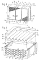
- Any catalyst body 12 is essentially made up of at least two, namely three identically trained and dimensioned, rigid with each other connected blocks 21 composed.
- Each block 21 has generally the shape of a parallelepiped, namely one Cuboid, so that the abutting surfaces of each Blocks 21 are in pairs at right angles to each other. Every block has an open at both ends, in cross section, in essentially square, namely rectangular sleeve 22 and a package 24 of compact, i.e. hole-free, alternating successive, separate, first sheet metal elements 25 and second sheet metal elements 26.
- Each Sleeve has a first wall 22a, a second wall 22b, one third wall 22c and fourth wall 22d.
- the four walls 22a-22d are essentially flat, but can possibly by using small radii of curvature curved transition sections be connected.
- the outside and inside surfaces of the walls are at least before connecting to the sheet metal elements in the essentially flat and smooth, i.e. free of grooves or ribs or other depressions and increases.
- the first wall 22a and the second wall 22b face away from each other and parallel to each other and to the end faces 12a, 12b of the Catalyst body 12.
- the third wall 22c and the fourth wall 22d face away from one another and parallel to one another and to Base 12c and the top surface 12d of the Catalyst body 12.
- the adjacent sleeves 22 lie with the flat outer surfaces of a first wall 22a or a second wall 22b to each other and are in the Butt joints rigidly connected.
- the three pods are for example along the vertical edges of FIG adjacent walls welded
- Each sheet metal element 25, 26 has four corners, a first Edge 25a or 26a, a second edge 25b or 26b, one third edge 25c or 26c and a fourth edge 25d or 26d.
- the four edges of each sheet metal element are at least in one Top view of this completely straight.
- the sheet metal elements 25, 26 therefore have the shape of a in plan view right-angled parallelogram, namely a rectangle.
- the first sheet metal elements 25 are completely flat.
- the second Sheet metal elements 26 are provided with shafts 26e everywhere. This are straight and to each other and to the first and second Edges 26a, 26b parallel. Every second sheet metal element 26 defines two flat surfaces that are on the lower one or upper side of the sheet metal element at the shaft apices of the shafts 26e nestle against the sheet metal element.
- the Sheet metal elements 25, 26 are in the associated sleeve 22 arranged that the first flat sheet metal elements 25 and planes defined by the second sheet metal elements Schmiege vom parallel to the base 12c and to Cover surface 12d of the catalyst body 12 and to the walls 22c, 22d of the sleeve 22.
- the first and second edges 25a, 25b, 26a, 26b of the sheet metal elements face away from each other and along their entire lengths the inner surfaces of the to these edges facing parallel walls 22a, 22b.
- the sheet metal elements fit fed in between the first and second walls between them a small one, for example at most 0.5 mm amounting game, so the first and second edges of all Sheet metal elements at least approximately on the inner surfaces of the butt first or second walls.
- Each sheet metal element 25, 26 is at least one edge section and namely at two or possibly even more apart Edge sections of its first edge 25a or 26a with the first wall 22a in a manner described in more detail connected, namely welded.
- Each sheet metal element 25, 26 is furthermore with at least one edge section and namely with two or possibly even more apart Edge sections of its second edge 25b or 26b with the second wall 22b firmly connected, namely welded.
- the the Walls 22a, 22b connecting with the sheet metal elements Welded connections lie on two strip-shaped ones Regions of the walls 22a, 22b and are in Figures 3, 4 and 8 schematically represented by dots and with 27 designated.
- the stripe-shaped areas run perpendicular to walls 22c and 22d.
- Each not on Located at the end of a package 24 is the second sheet metal element 26 at the crest of its waves 26e on the two him adjacent, flat, first sheet metal elements 25.
- To the Both ends of the package 24 can be second, for example Sheet metal elements 26 to be present with wave crests rest against the walls 22c and 22d. Limit the sheet metal elements passageways 29 separated in pairs, the parallel to the first and second edges 25a, 26a, 25b, 26b from the third edges 25c, 26c to the fourth edges of the sheet metal elements 25 and 26 extend.
- the sheet metal elements 25, 26 of a package 24 together form a matrix, which the relevant sleeve 22 - apart from the passages 29 - in essentially completely filled out.
- the third edges 25c, 26c the sheet metal elements are flush with those on the concerned Side of the sleeve 22 existing edges of the sleeve walls. The same applies to the fourth edges 25d, 26d of the Sheet metal elements and the edges present at these edges the sleeve 22.
- the outer surfaces of the fourth walls 22d of the three sleeves 22 together form the top surface 12d of the Catalyst body 12.
- the third edges 25c, 26c of the Sheet metal elements of the three blocks 21 and those at these edges existing edges of the sleeve walls together form the inner Mouth surface 12e.
- the fourth edges 25d, 26d of the Sheet metal elements of the three blocks 21 together with the these edges are flush with the outer edges of the sleeve walls Mouth surface 12f.
- the passages 29 have in the Mouth surfaces 12e, 12f lying mouths
- Each sheet metal element 25, 26 has one in FIG. 8 visible, metallic, steel core 31 or 33, which is formed from a sheet metal lamella. On both mutually facing surfaces of the cores or laminations of the A sheet 32 or 34 is applied to sheet metal elements 25, 26, which completely covers the two surfaces of the core 31, 33.
- Each coating 32 or 34 consists largely of the non-metallic, porous "wash coat".
- Each cover contains furthermore catalytically active material which is at least one Has precious metal, for example platinum and rhodium and for example the surface facing away from the core 31 or 33 every "wash coat" is at least somewhat complete covered.
- Each package 24 and its sheet metal elements 25, 26 have one parallel to the first and second edges 25a, 26a and 25b, Dimension 26b of the sheet metal elements measured a. This is the same the distance of the third edges 25c, 26c from the fourth Edges 25d, 26d and is, for example, approximately 30 mm.
- Each package and its sheet metal elements 25, 26 have one in the Top view of the sheet metal elements parallel to the third and fourth edges 25c, 25d, 26c, 26d of the sheet metal elements 25 and 26 and perpendicular to the shafts 26e and parallel to the measured against these cuddly, flat lubricating surfaces Dimension b.
- the dimension b is preferably at most 50 mm, preferably at least 20 mm, expediently 30 mm to 40 mm, for example approximately 35 mm.
- Each package 24 has at right angles to the flat sheet metal elements 25 and called flat planing surfaces a dimension c. This is for example larger than dimension b and is preferably 60 mm to 80 mm and for example about 70 mm.
- the walls of the sleeves 22 all have the same thickness d.
- the thickness of the metallic cores 31, 33, designated s 1 in FIG. 8, is preferably at most 0.1 mm and, for example, approximately 0.05 mm.
- the thickness s 2 of the coatings 32 and 34 is preferably at most 0.1 mm and for example approximately 0.03 mm.
- the thickness S 3 of a sheet metal element 25 or 26 having coatings 32, 34 on both surfaces facing away from one another is at most 0.3 mm and, for example, approximately 0.11 mm. 8 also shows the wave height h. This is measured between mutually facing surfaces from corrugation crest to crest of a second sheet metal element 26 provided with coatings 34 and is accordingly equal to the distance between the facing surfaces of two adjacent, flat sheet metal elements 25.
- the wave height h is preferably at most 1 mm and for example about 0.5 mm to 0.7 mm.
- the wavelength ⁇ likewise indicated in FIG. 8 is preferably at least equal to the wave height h and is preferably at most four times the wave height.
- the wavelength can be approximately 1 mm to 2 mm, for example.
- a package of sheet metal elements in a cross section perpendicular to the waves preferably has at least 150 passes per cm 2 and, for example, approximately 193 passes per cm 2 (approximately 1250 passes per square inch).
- the thicknesses of the sheet metal elements and the wave heights as well as the wavelengths are not drawn to scale in the various figures and that, for example, the thicknesses of the sheet metal elements, the wave height and the wave length are actually smaller compared to dimension b than in FIG Fig. 4.
- Example first sleeves 22 with the intended dimensions and Sheet metal elements 25, 26 with coatings and the intended Create dimensions can, for example, from a tube with a jacket which is quadrangular in cross section be cut off at one in its longitudinal direction is welded.
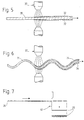
- the sheet metal elements 25, 26 can first be one in FIG. 5 apparent, flat, band-shaped carrier 35 and one in the Fig. 6 apparent, band-shaped carrier 36 with across produce waves running in the longitudinal direction.
- the band-shaped carrier 35, 36 consist of bare sheet metal and have a width equal to the intended dimension a is.
- the carriers are then in a longitudinal direction on one Spray device 37 transported past, as in the figures 5, 6 is indicated by arrows.
- the two each other facing surfaces of the carrier 35, 36 are by means of Spray device 37 in one pass or in several Runs sprayed with liquid coating material that after the drying forms coatings that are the same in Figures 5, 6 like the coatings of the finished sheet metal elements with 32 or 34 are designated and the beams across the entire width and in cover all directions without interruption.
- the one with covers provided carrier 35 is then in its longitudinal direction stepwise one shown in FIG. 7 Separation device 41 supplied and from this in level Sheet metal elements 25 separated, i.e. cut up their metallic cores 31 from sections of the original band-shaped carrier 35 exist.
- the corrugated, with covers provided carrier 36 is analogously in corrugated sheet metal elements 26th cut up.
- sheet metal elements 25, 26 are alternately one on the other stacked and the stacks or packages thus formed 24 in Sleeves 22 used. Then the sheet metal elements at their edges 25a, 26a, 25b, 26b by temporary Melt metallic material firmly to the walls 22a or 22b connected, namely welded.
- Welding device 42 with at least one electrode used.
- the Sleeve 22 is arranged, for example, such that its Wall 22a just to be welded above the sheet metal elements 25, 26 is located and is approximately horizontal.
- the electrode is on the sheet metal elements 25, 26 facing away from the with this wall 22a of the sleeve 22 to be welded Arc 43 generated.
- the electrode continuously at right angles in the direction of arrow 44 the edges 25a, 26a of the sheet metal elements 25 and 26 along the Wall 22a moves relative to the sleeve 22.
- the welding device is also formed around a the free end of the electrode and the arc enveloping an inert gas, for example at least one noble gas, or carbon dioxide produce. During the welding process, a stripe-shaped Area of the wall 22a temporarily softened and more or melted less. Furthermore, for example, another Filler metal are supplied.
- the amount of filler fed is dimensioned in such a way that the filler material faces the inside flowing wall material at least approximately replaced, so that there is no continuous slit in the wall.
- a small depression are formed so that the sleeves 22 afterwards without Post-processing with the flat outer surfaces together can concern.
- the coatings can 32, 34 may be damaged a little. Any damage to the covers is, however, very bad small, to the welded edge sections of the sheet metal elements adjacent areas limited by these.
- the catalyst 1 can be used, for example into an exhaust pipe of an exhaust device of the gasoline internal combustion engine of an automobile.
- the exhaust gas flows through the inlet 8 into the inner cavity 16, is in this deflects and flows at the as exhaust gas entry surfaces serving, facing, inner, second Mouth surfaces 12e of the two catalyst bodies 12 in the inner ends of the passages 29.
- the exhaust gas then flows through the passages 29 to the outer facing away from each other Mouth surfaces 12f of the two catalyst bodies 12.
- the exhaust gas becomes catalytic when flowing through the passages 29 treated, especially cleaned and detoxified, occurs the outer ones, which serve as exhaust gas outlet surfaces Mouth surfaces 12f again out of the catalyst bodies 12 and then flows through the outer cavity 17 to the outlet 9.
- the from the cylindrical portion 8a of the inlet 8th Transition section 8b extending towards the inner cavity 16 of the inlet 8 contributes to the fact that when the Exhaust gas in the inner cavity 16 practically no turbulence and there is little pressure loss.
- the catalyst bodies 12 are, for example only mechanically with the first end surfaces 12a connected to the wall 4 of the housing 3, so that the Catalyst body only at the end surfaces 12a heat over solid Release metallic parts into the environment by heat conduction can. Furthermore, the exhaust gas flows out of the inlet 8 directly into the inner cavity 16. This is through the Catalyst body 12 and the plates 13 practically completely separated from the wall 4 of the housing 3. The exhaust gas can accordingly between the outflow from the Mouth opening of the inlet 8 and the flow into the Catalyst body 12 practically no heat to the environment submit.
- the two catalyst bodies 12 also only give relatively slowly heat to the environment via the housing wall from. On a cold start - i.e. if the catalyst 1 and the Engine when starting the latter still ambient temperature have - are therefore at least those of the inner cavity 16th adjacent areas of the catalyst body 12 by the exhaust gas quickly warmed to a temperature that is an effective allows catalytic treatment of the exhaust gas.
- the small cross-sectional dimensions of the passages 29 ensure that the exhaust gas flows through the passageways intensive contact with the catalytically active material which has coatings 32 and 34.
- the intense contact of the exhaust gas with the catalytically active material gives a high catalytic efficiency.
- This high catalytic Efficiency helps that the catalyst and the whole catalyst - based on a given, maximum Flow rate of the through the two catalyst bodies flowing exhaust gas - relatively small and light can be trained. Accordingly, the Production of the catalyst means only a proportionate small amount of expensive precious metals, catalytically active material and even a small amount also quite expensive, forming the cores 31, 33, metallic material.
- the exhaust gas can flow out of the Catalyst bodies 12 on which the catalyst means 11 in Outer cavity 17 completely enclosing the cross section to distribute. If the exhaust gas from the catalyst bodies through the outer cavity 17 flows into the outlet passage 18, therefore only a small one is created in the outer cavity Pressure loss.
- the catalyst means 11 are in operation - starting from ambient temperature - heated to temperatures that at least in places be more than 500 ° C. At the Interrupting or stopping the operation Catalyst medium cooled back to ambient temperature, the different parts of the catalyst means 11 expand and contract again. It also causes this Exhaust gas generating engine vibrations, which together with the accelerations caused by driving the automobile act on the catalyst.
- the waves 26e stiffen the Sheet metal elements 26, the shafts 26e also those on them support the flat sheet metal elements 25. Since the Dimension b of the sheet metal elements is significantly smaller than that Length L of an entire catalyst body 12, deform and the sheet metal elements bend during operation as a result of Temperature changes and that on the catalyst agent accelerations only relatively little.
- the walls of the sleeves 22 compared to the External dimensions of the catalyst body and in particular in Compared to the length L are relatively thin, the walls of the Sleeves 22 and in particular the walls 22a, 22b only one relatively small part of the total surface area of the inner cavity 16 adjacent inner mouth surface 12e of a catalyst body. Accordingly, the effect Sleeves 22 only a small reduction for the catalytic Treatment of usable volume of the catalyst body 12. Furthermore the sleeves 22 only increase the weight of the catalyst body relatively few.
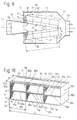
- the catalyst 51 shown in FIG. 9 defines an axis 52 and has a housing 53 with a wall 54. Die the latter has a jacket 55 which is parallel to the axis 52, but in Cross section is possibly oval or flattened, so that the Sheath a measured parallel to the plane of the drawing Cross-sectional dimension that is larger than that Cross-sectional dimension measured perpendicular to the plane of the drawing.
- the housing 53 has two end walls 56, 57, one Inlet 58 and an outlet 59. Housing 53 contains Catalyst means 61 with two catalyst bodies 62, which in the drawn longitudinal section are arranged V-shaped. Everyone Catalyst body 62 has four rigidly interconnected Blocks 71.
- Each block 71 has a sleeve and one in it Arranged package of sheet metal elements similar to that Sheet metal elements 25 and 26 are formed.
- the parallel to the Dimension a measured for shafts of sheet metal elements and sleeves for example, a block 71 is a little larger than that Dimension a of the sheet metal elements 25, 26 and is, for example about 40 mm.
- dimension b measured perpendicular to the waves Sheet metal elements of blocks 71 are the same as for example the sheet metal elements 25, 26 of the blocks 21 approximately 35 mm.
- walls of the sleeves of blocks 71 may be the same as the walls of the sleeves 22 of the blocks 21 have a thickness of 1.5 mm to have.
- the length L of a catalyst body 62 is then for example about 152 mm. So far nothing else has been written, the catalyst 51 can be configured similarly be like catalyst 1.
- the catalyst body 82 shown in FIG. 10 is like the catalyst bodies 12 and 62 cuboid and has two end surfaces 82a, 82b facing away from one another, a base surface 82c, one of these facing away surface 82d, an inner Muzzle surface 82e and an outer surface facing away from it Mouth surface 82f.
- the catalyst body 82 can for example, together with a mirror-symmetrical one Catalyst bodies are arranged in a housing in such a way that its inner mouth surface 82e connects to an inner cavity and its outer mouth surface 82f to an outer one Adjacent cavity.
- the catalyst body 82 has two superimposed ones Rows of blocks 91.
- Each block 91 has one in cross section rectangular sleeve 92 with a first wall 92a, one for this parallel second wall 92b, a third wall 92c and one to this parallel fourth wall 92d.
- the sleeves 92 of the top row lie with the first wall 92a on the second Wall 92b of a sleeve 92 of the lower row.
- the middle sleeve of each of the two rows with their walls 92c and 92d on the wall 92d and 92c of an adjacent sleeve on.
- the sleeves lying against each other are together welded.
- Each sleeve 92 contains a package 94 of alternating successive levels and waves having sheet metal elements.
- the flat sheet metal elements and the planes defined by the corrugated sheet metal elements Sliding surfaces are parallel to the end surfaces 82a, 82b of the Catalyst body and to the walls 92c, 92
- the end surface 82a, 82b of the catalyst body 82 are formed by the walls 92d and 92c of two sleeves 92.
- the Base 82c and cover 82d are through the walls 92a and 92b of the lower and upper sleeves formed.
- the inner opening surface 82e of the catalyst body 82 is through the third edges of the sheet metal elements and those with them Edges form flush edges of sleeves 92.
- the exterior Muzzle surface 82f is through the fourth edges of the Sheet metal elements and the edges of the flush with these edges Pods formed.
- the dimension a measured parallel to the waves Sheet metal elements and sleeves 92 can, for example, 30 mm to 100 mm be.
- the dimension measured perpendicular to the waves b the sheet metal elements can, for example, be the same as for the Sheet elements 25, 26 are approximately 35 mm.
- the Dimension measured perpendicular to the flat sheet metal elements c of a package of sheet metal elements can, for example, be the same as for the catalyst bodies 12 amount to approximately 70 mm.
- the walls for example, the sleeves 92 can be 1.5 mm thick.
- the length L of the whole catalyst body then becomes about 219 mm.
- first with the second edge of each Sheet metal element with more than two spaced apart weld standing edge sections to a wall.
- first and second margin along its entire length or along only one single contiguous but then relatively long Weld the edge section with a wall.
- You could also use to weld the sheet metal elements use at least one welding device on the walls instead of at least one electrode, at least one Has gas burner.
- the sheet metal elements and one with these too welding wall can then be welded with a Flame from the side of the wall facing away from the sheet metal elements be heated here.
- the dimensions of the sleeves and sheet metal elements can be in certain limits can be varied.
- the perpendicular to the Dimension b of the sheet metal elements measured in waves is, however preferably at most 50 mm, preferably at least 20 mm and for example 30 mm to 40 mm.
- a catalyst body can also have more than four inches blocks arranged in a row or possibly just two blocks with a sleeve and a package of sheet metal elements exhibit.
- the length L of a catalyst body can then for example in a range from about 60 mm to 500 mm lie.
- a catalyst body may even be produced be the only one block with one between walls a sleeve arranged package of sheet metal elements.
- each block could only have two instead of one sleeve have separate walls between which a package of Sheet metal elements is arranged and of which the one, first Wall with the first edges and the other, second wall with the second edges of the sheet metal elements is welded.
- the sheet metal elements can, for example, in the top view be square instead of rectangular. Furthermore, could the catalyst bodies have base and top surfaces, which have the shape of an oblique parallelogram. The Shapes of the sleeves and sheet metal elements would then be appropriate adjust, then the sheet metal elements in plan view can also be skewed.
- the jackets of the housing of the catalysts 1 and 51 can on the sides located at the top and bottom in FIG. 2 be flattened or approximately rectangular in cross section and on the base surfaces 12c and top surfaces 12d of the Catalyst body 12 or the corresponding surfaces of the Catalyst body 62 abut.
- Manufacture catalytic converter whose housing has more than two Catalyst body, for example three or four Contains catalyst body. These can then be parallel to Axis of the catalyst and so distributed around it be that they cross-section an inner cavity limit. The latter can then be an approximation contain pyramidal boundary element that together with the inner mouth surfaces of the catalyst body bounded free cavity area, the cross-sectional area of the Intake off decreases approximately or exactly linearly.
Landscapes
- Chemical & Material Sciences (AREA)
- Engineering & Computer Science (AREA)
- Chemical Kinetics & Catalysis (AREA)
- Combustion & Propulsion (AREA)
- Mechanical Engineering (AREA)
- General Engineering & Computer Science (AREA)
- Health & Medical Sciences (AREA)
- Toxicology (AREA)
- Materials Engineering (AREA)
- Organic Chemistry (AREA)
- Physics & Mathematics (AREA)
- Optics & Photonics (AREA)
- Plasma & Fusion (AREA)
- Exhaust Gas After Treatment (AREA)
- Catalysts (AREA)
- Exhaust Gas Treatment By Means Of Catalyst (AREA)
Description
Die Erfindung betrifft ein Verfahren zur Herstellung eines Katalysatorkörpers für die katalytische Behandlung von Gas, insbesondere für die katalytische Reinigung von Abgas eines Verbrennungsmotors. Solche zum Einbau in ein Gehäuse eines Katalysators vorgesehene Katalysatorkörper werden häufig auch als Substrat bezeichnet. Der Verbrennungsmotor kann zum Beispiel zu einem Automobil oder sonstigen Motorfahrzeug gehören oder stationär angeordnet sein.The invention relates to a method for producing a Catalyst body for the catalytic treatment of gas, especially for the catalytic purification of exhaust gas Internal combustion engine. Such for installation in a housing Catalyst bodies provided for catalyst are often also referred to as the substrate. The internal combustion engine can Example of an automobile or other motor vehicle belong or be arranged stationary.
Ein aus der US-A 5 187 142 bekannter Katalysator besitzt einen Katalysatorkörper mit aufeinander gestapelten, viereckförmigen Wellblechelementen, von denen jedes in einem Fischgrätenmuster angeordnete Wellen hat. Zwischen aufeinanderfolgenden Gruppen solcher Wellblechelemente sind Halteblechelemente angeordnet, von denen jedes einen viereckförmigen, gewellten Hauptabschnitt und bei zwei einander abgewandten Rändern von diesem einen abgewinkelten Lappen besitzt. Bei der Herstellung eines derartigen Katalysatorkörpers werden zuerst blanke Wellblechelemente und Halteblechelemente hergestellt und aufeinander gestapelt. Dann werden die Blechelemente bei ihren Berührungspunkten durch Hartlöten oder Entladungsschweissen miteinander verbunden und die einander überlappenden Lappen miteinander und möglicherweise auch mit den Wellblechelementen verschweisst, so dass ein Paket von fest miteinander verbundenen Blechelementen entsteht, wobei die Lappen zusammen Innen- und Aussenflächen mit Stufen bilden. Danach werden Überzüge mit katalytisch aktivem Material auf die miteinander verbundenen Blechelemente aufgebracht. Die Blechelemente begrenzen dann zusammen Durchgänge für das Abgas.A catalyst known from US-A 5 187 142 has a catalyst body with stacked, quadrangular corrugated iron elements, each in one Herringbone pattern has arranged waves. Between successive groups of such corrugated iron elements Bracket elements arranged, each one square, corrugated main section and at two mutually facing edges of this one angled Owns rag. In the manufacture of such Catalyst body are first bare corrugated iron elements and Bracket elements made and stacked on top of each other. Then the sheet metal elements through at their points of contact Brazing or discharge welding joined together and the overlapping lobes with each other and possibly also welded to the corrugated iron elements, so that a package of firmly connected Sheet metal elements are created, the lobes together inside and Form external surfaces with steps. After that, coatings are made with catalytically active material on the interconnected Sheet metal elements applied. The sheet metal elements then limit together passages for the exhaust gas.
Bei diesem Herstellungsverfahren erfordert das Herstellen und Zusammenbauen der Blechelemente relativ viele Arbeitsschritte. Ferner ist es schwierig und aufwendig, nach dem Zusammenbauen eines Pakets von Blechelementen einigermassen gleichmässige Überzüge auf die ganzen Flächen der Wellblechelemente und der Hauptabschnitte der Halteblechelemente aufzubringen. Damit die genannten Flächen wenigstens einigermassen vollständig von Überzügen bedeckt werden, müssen die Wellen relativ hoch gemacht werden. Zudem müssen die Wellen benachbarter Blechelemente einander kreuzen, so dass jedes Paar von einander benachbarten Blechelementen nur einen einzigen Durchgang begrenzt, der nur bei den Berührungspunkten der Blechelemente unterteilt ist. Der Katalysatorkörper hat daher in einem quer zur allgemeinen Strömungsrichtung des Abgases verlaufenden Querschnitt nur eine geringe Anzahl Durchgänge pro Querschnittsflächeneinheit, wobei die einander gegenüberstehenden Abschnitte der Oberflächen eines Durchgangs im allgemeinen grosse Abstände voneinander haben. Der Katalysatorkörper ergibt aus diesen Gründen nur eine geringe Reinigungswirkung pro Volumeneinheit des Katalysatorkörpers und muss daher zur Ermöglichung einer ausreichenden Abgasreinigung relativ gross ausgebildet werden. Der bekannte Katalysatorkörper und ein mit einem solchen ausgerüsteter Katalysator haben daher die Nachteile, dass sie viel Platz benötigen und entsprechend schwer sind. Die grosse Masse des bekannten Katalysatorkörpers vergrössert zudem bei einem Kaltstart die Zeit zum Aufheizen des Katalysatorkörpers auf eine für eine wirksame Abgasreinigung günstige Temperatur. Zudem enthalten die Katalysatorkörper teure Materialien, insbesondere normalerweise mindestens ein in den Überzügen vorhandenes Edelmetall, so dass die grosse Masse eines bekannten Katalysatorkörpers auch die Herstellungskosten des Katalysators erhöht.This manufacturing process requires manufacturing and assembling the sheet metal elements relatively many steps. Furthermore, it is difficult and expensive after To some extent assemble a package of sheet metal elements uniform coatings on the entire surface of the Corrugated sheet elements and the main sections of the holding plate elements to apply. So that the areas mentioned at least reasonably completely covered by coatings the waves have to be made relatively high. In addition the waves of neighboring sheet metal elements must cross each other, so that each pair of adjacent sheet metal elements only limited to one pass, which is only possible with the Points of contact of the sheet metal elements is divided. The The catalyst body therefore has a cross to the general Exhaust gas flow direction cross section only a small number of passes per cross-sectional area unit, the opposing sections of the Surfaces of a passage generally have large gaps from each other. The catalyst body results from these Reasons only a low cleaning effect per unit volume of the catalyst body and must therefore be possible to enable a sufficient exhaust gas purification are relatively large. The known catalyst body and one with such equipped catalyst therefore have the disadvantages that they take up a lot of space and are correspondingly heavy. The size Mass of the known catalyst body also increases a cold start the time to heat up the catalyst body to a temperature that is favorable for effective exhaust gas cleaning. In addition, the catalyst bodies contain expensive materials, especially usually at least one in the coatings existing precious metal, so that the large mass of a known catalyst body also the manufacturing cost of Catalyst increased.
Bei einem aus der JP-A 6 254 409 bekannten Verfahren zur Herstellung eines Katalysatorkörpers werden ebene und gewellte Blechelemente in zwei Hülsen eingesetzt und in diesen befestigt. Dann werden die beiden Hülsen miteinander verschweisst. Danach werden Überzüge mit einem katalytisch aktiven Material auf die Blechelemente aufgebracht. Die Wellen der gewellten Blechelemente eines derart hergestellten Katalysatorkörpers müssen ebenfalls grosse Wellenhöhen haben, damit man nach dem Zusammenbauen der Blechelemente noch Überzüge auf diese aufbringen kann. Das aus der JP-A 6 254 409 bekannte Herstellungsverfahren und der mit diesem hergestellte Katalysatorkörper haben daher weitgehend ähnliche Nachteile wie das Herstellungsverfahren und der Katalysatorkörper gemäss der US-A 5 187 142.In a method known from JP-A 6 254 409 for Manufacturing a catalyst body will be flat and corrugated Sheet metal elements inserted in two sleeves and in these attached. Then the two sleeves together welded. After that, coatings with a catalytic active material applied to the sheet metal elements. The waves the corrugated sheet metal elements of a manufactured in this way Catalyst body must also have large wave heights, so that after assembling the sheet metal elements Can apply coatings on this. That from JP-A 6 254 409 known manufacturing method and the manufactured with it Catalyst bodies therefore have largely similar disadvantages how the manufacturing process and the catalyst body according to U.S. Patent 5,187,142.
Aus den Publikationen EP-A 0 676 534 und EP-A 0 676 535 sind Katalysatorkörper bekannt, von denen jeder viereckförmige, ebene und gewellte Blechelemente und bei zwei einander abgewandten Rändern der Blechelemente angeordnete Distanzelemente besitzt. Für die Herstellung eines derartigen Katalysatorkörpers stellt man gemäss der EP-A 0 676 534 Blechelemente her, die einen gewellten, mit Überzügen versehenen Hauptabschnitt und ebene, blanke Randabschnitte haben, an denen Distanzelemente durch Punktschweissen provisorisch befestigt sind. Ferner werden ebene Blechelemente mit einem Überzüge aufweisenden Hauptabschnitt und blanken Randabschnitten hergestellt. Danach werden die Blechelemente aufeinandergestapelt und entlang ihrer genannten Ränder mit den Distanzelementen und miteinander verschweisst. Dieses Herstellungsverfahren ist jedoch ziemlich aufwendig. From the publications EP-A 0 676 534 and EP-A 0 676 535 catalyst bodies are known, each of which is square, flat and corrugated sheet metal elements and with two mutually facing edges of the sheet metal elements arranged Has spacer elements. For the production of such Catalyst body is made according to EP-A 0 676 534 Sheet metal elements ago, a corrugated, with coatings provided main section and flat, bare edge sections have spacer elements by spot welding are temporarily attached. Furthermore, flat sheet metal elements with a coated main section and bare Edge sections made. Then the sheet metal elements stacked on top of each other and along their edges the spacers and welded together. This However, the manufacturing process is quite complex.
Bei hergestellten Katalysatoren dieser Art betragen die Längen der Katalysatorkörper und Blechelemente mindestens 100 mm und die Breiten der Distanzelemente ungefähr 5 mm. Die Distanzelemente und die von diesen bedeckten, blanken Randabschnitte der Blechelemente haben eine relativ grosse Masse, die bei einem Kaltstart die Zeit zum Aufheizen der Katalysatorkörper auf die optimale Betriebstemperatur verzögert. Dauerversuche mit Katalysatoren der beschriebenen Art haben zudem gezeigt, dass bei starken Beanspruchungen, insbesondere bei relativ langen Katalysatorkörpern, bleibende Verformungen von Blechelementen entstehen können, welche die Wirkung der Katalysatorkörper beeinträchtigen.In the case of catalysts of this type, the Lengths of the catalyst body and sheet metal elements at least 100 mm and the widths of the spacers about 5 mm. The Spacer elements and the bare ones covered by them Edge sections of the sheet metal elements have a relatively large Mass, the time to heat up the cold start Catalyst body to the optimal operating temperature delayed. Endurance tests with catalysts of the described Art have also shown that with heavy loads, especially with relatively long catalyst bodies, permanent Deformations of sheet metal elements can occur, which the Impact the effect of the catalyst body.
Der Erfindung liegt die Aufgabe zugrunde, ein Verfahren zur Herstellung eines Katalysatorkörpers zu schaffen, das ermöglicht, Nachteile der bekannten Herstellungsverfahren und der damit hergestellten Katalysatorkörper zu vermeiden. Es soll insbesondere ausgehend von dem aus der EP-A 0 676 534 bekannten Verfahren ermöglicht werden, die durch die Distanzelemente bedingte Komplikation des Herstellungsverfahrens sowie Vergrösserung der Katalysatorkörper-Masse und den ebenfalls durch die Distanzelemente verursachten Platzverlust möglichst zu vermeiden. Dabei soll es möglich sein, auch bei kleinen, vorgesehenen Querschnittsabmessungen der Durchgänge in einfacher Weise einigermassen gleichmässige Überzüge auf die ganzen an die Durchgänge angrenzenden Flächen der Blechelemente aufzubringen. Ferner soll der Katalysatorkörper wirtschaftlich herstellbar und dauerhaft sein.The invention has for its object a method to create a catalyst body that allows disadvantages of the known manufacturing processes and to avoid the catalyst body thus produced. It is intended in particular based on that from EP-A 0 676 534 known methods are made possible the complication of the manufacturing process due to the spacer elements as well as enlargement of the catalyst body mass and also by the To avoid spacing elements causing loss of space if possible. In doing so it may be possible even with small, intended cross-sectional dimensions of the passages in simple, reasonably even coatings on the whole areas of the Apply sheet metal elements. Furthermore, the catalyst body be economical to manufacture and durable.
Diese Aufgabe wird gemäss der Erfindung durch ein
Verfahren zur Herstellung eines Katalysatorkörpers mit den
Merkmalen des Anspruchs 1 gelöst.This object is achieved according to the invention by a
Process for producing a catalyst body with the
Features of
Die Erfindung betrifft ferner einen Katalysatorkörper mit
den Merkmalen des Anspruchs 18 und einen Katalysator mit den
Merkmalen des Anspruchs 20.The invention further relates to a catalyst body
the features of
Gemäss der Erfindung werden zuerst Blechelemente mit Überzügen hergestellt. Danach werden die bereits Überzüge aufweisenden Blechelemente zur Bildung eines Pakets derart aufeinander gestapelt und zwischen zwei Wänden angeordnet, dass die Blechelemente zusammen Durchgänge für das Gas begrenzen. Diese Reihenfolge der Verfahrensschritte ermöglicht, auch bei kleinen vorgesehenen Querschnittsabmessungen der Durchgänge in einfacher und wirtschaftlicher Weise Überzüge auf die ganzen Flächen aufzubringen, die nachher beim fertigen Katalysatorkörper an die Durchgänge angrenzen.According to the invention, sheet metal elements are first used Coatings made. After that, the already coatings having sheet metal elements to form a package such stacked on top of each other and arranged between two walls, that the sheet metal elements together passages for the gas limit. This sequence of process steps enables, even with small intended cross-sectional dimensions of the passages in simple and economical Way to apply coatings to the entire surface that afterwards with the finished catalyst body to the passages adjoin.
Die Überzüge weisen katalytisch aktives Material, nämlich vorzugsweise mindestens ein Edelmetall, beispielsweise Platin und Rhodium auf. Die Überzüge enthalten zudem vorzugsweise ein poröses, zur Bildung einer rauhen, grossen Oberfläche dienendes, nicht-metallisches Material, das mindestens ein Oxid, beispielsweise Aluminiumoxid aufweist und den sogenannten "wash coat" bildet. Dieses nicht-metallische Material kann dann volumen- und gewichtsmässig den grössten Teil des Überzugs bilden. Das erfindungsgemässe Verfahren ermöglicht, die Überzüge derart gleichmässig auf die Flächen der Blechelemente aufzubringen, dass sie bei den ganzen Flächen ungefähr gleiche Dicken, Strukturen und Zusammensetzungen haben. Zur Bildung eines Überzugs kann man zum Beispiel gleichzeitig mindestens ein nicht-metallisches Material und mindestens ein katalytisch aktives Edelmetall auf einen zur Bildung von Blechelementen dienenden, metallischen Träger aufbringen, beispielsweise zusammen mit einem flüssigen Dispersions- und/oder Lösungsmittel aufsprühen. Es besteht auch die Möglichkeit, nacheinander Überzugsmaterialien mit verschiedenen Zusammensetzungen auf einen Träger aufzubringen.The coatings have catalytically active material, namely preferably at least one noble metal, for example platinum and rhodium. The coatings also preferably contain a porous, to form a rough, large surface serving, non-metallic material that is at least one Has oxide, for example aluminum oxide and the so-called "wash coat" forms. This non-metallic Material can then be the largest in terms of volume and weight Form part of the coating. The method according to the invention allows the coatings to be so even on the surfaces of the sheet metal elements that they apply to the whole Surfaces of approximately equal thicknesses, structures and Have compositions. To form a coating you can for example at least one non-metallic at the same time Material and at least one catalytically active precious metal one used to form sheet metal elements, metallic Apply carrier, for example together with a liquid Spray on dispersion and / or solvent. It exists also the possibility of using coating materials one after the other to apply different compositions to a support.
Es wurde überraschend gefunden, dass man auch Blechelemente, deren zwei einander abgewandten Flächen vollständig und bis zu den mit den Wänden zu verbindenden Rändern mit zum grössten Teil aus nicht-metallischem Material bestehenden Überzügen versehen bzw. gebildet sind, durch Schmelzen von metallischem Material, nämlich durch Schweissen, fest und dauerhaft mit den Wänden verbinden kann.It was surprisingly found that one too Sheet metal elements, the two surfaces facing away from each other completely and up to those to be connected to the walls Edges with mostly non-metallic material existing coatings are provided or formed by Melting of metallic material, namely by welding, can firmly and permanently connect to the walls.
Der Erfindungsgegenstand wird anschliessend anhand von in
der Zeichnung dargestellten Ausführungsbeispielen näher
erläutert. In der Zeichnung zeigt
Es sei noch darauf hingewiesen, dass verschiedene Figuren schematisch und zum Teil nicht massstäblich gezeichnet sind.It should also be noted that different figures are drawn schematically and partly not to scale.
Der in den Figuren 1 und 2 ersichtliche Katalysator 1
dient für die katalytische Behandlung von Gas, nämlich für die
katalytische Behandlung von Abgas eines Benzin-Verbrennungsmotors.
Der Katalysator 1 definiert eine Achse 2
und besitzt ein Gehäuse 3. Dessen Wandung 4 besitzt mehrere
Wandungsteile, nämlich einen zur Achse 2 koaxialen,
parallelen, beispielsweise zylindrischen, im Querschnitt
kreisförmigen Mantel 5, eine ebene Endwand 6 und eine sich vom
Mantel 5 weg konisch verjüngende Endwand 7.The
Das Gehäuse 3 ist mit einem Einlass 8 und einem Auslass 9
versehen. Der Einlass 8 besitzt einen zur Achse 2 koaxialen
zylindrischen, im Querschnitt kreisförmigen Abschnitt 8a, der
durch einen Übergangsabschnitt 8b mit der Endwand 6 verbunden
ist. Der Auslass 9 ist koaxial zur Achse 2, im wesentlichen
zylindrisch und mit der Endwand 7 verbunden. Die verschiedenen
Wandungsteile, der Einlass 8 und der Auslass 9 bestehen aus
einem metallischen Material, beispielsweise rostfreiem Stahl,
und sind starr und dicht miteinander verbunden, beispielsweise
verschweisst, könnten jedoch stattdessen mindestens teilweise
durch Bördelverbindungen verbunden sein. The
Der dicht gegen die Umgebung abgeschlossene Innenraum des
Gehäuses 3 enthält Katalysatormittel mit zwei länglichen
Katalysatorkörpern 12. Diese sind im in der Fig. 1
gezeichneten, durch die Achse 2 verlaufenden Längsschnitt
V-förmig angeordnet. Jeder Katalysatorkörper 12 hat im
wesentlichen die Form eines Parallelepipeds nämlich eines
Quaders. Jeder Katalysatorkörper 12 hat dementsprechend sechs
Flächen, die einander paarweise abgewandt und paarweise
zueinander parallel sind, nämlich eine erste Fläche bzw.
Endfläche 12a, eine dieser abgewandte, zweite Fläche bzw.
Endfläche 12b, eine dritte Fläche bzw. Grundfläche 12c, eine
dieser abgewandte, vierte Fläche bzw. Deckfläche 12d, eine
fünfte Fläche bzw. innere Mündungsfläche 12e und eine dieser
abgewandte, sechste Fläche bzw. äussere Mündungsfläche 12f.The interior of the
Die beiden Katalysatorkörper 12 sind bei den Kanten
zwischen den Endflächen 12a und den inneren Mündungsflächen
12e fest und dicht mit der Endwand 6 verbunden, nämlich
verschweisst. Die beiden Katalysatorkörper stossen bei der
zwischen den Endflächen 12b und den inneren Mündungsflächen 12e
vorhandenen Kanten aneinander an und sind dort fest und dicht
miteinander verbunden, nämlich verschweisst. Ferner sind zwei
Platten 13 vorhanden, von denen eine an den Grundflächen 12c
und die andern an den Deckflächen 12d der beiden
Katalysatorkörper 12 anliegt. Die beiden Platten 13 bestehen
aus Stahl und sind über die ganze Länge der Katalysatorkörper
12 fest und dicht mit diesen verbunden, nämlich verschweisst.
Ferner sind die beiden Platten 13 mindestens beim mittleren
Bereich von ihren dem Einlass 8 zugewandten Rändern fest und
dicht mit der Endwand 6 verbunden, nämlich verschweisst.The two
Der Einlass 8 umschließt im Querschnitt einen Einlass-Durchgang
15. Dieser mündet bei der Endwand 6 in einen im
Querschnitt von den beiden Katalysatorkörpern 12 und den
beiden Platten 13 umschlossenen, inneren Hohlraum 16. Dieser
ist bei seinem mit dem Einlass verbundenen Ende im Querschnitt
viereckförmig, nämlich rechteckförmig. Der Mantel des
Übergangsabschnitts 8b ist mindestens bei gewissen
Umfangsbereichen gegen die Achse 2 geneigt, so dass der von
ihm begrenzte Abschnitt des Einlass-Durchgangs 15 bei dessen
mit dem inneren Hohlraum 16 verbundenem Ende ungefähr die
gleiche Querschnittsabmessung wie der innere Hohlraum 16 hat.
Die Breite und die Querschnittsfläche des inneren Hohlraums 16
nehmen im vom Einlass 8 weg verlaufender Richtung linear bis
mindestens annähernd auf den Wert Null ab, so dass sich der
innere Hohlraum 16 an seinem dem Einlass abgewandten Ende
mindestens annähernd zu einer geraden Linie verengt. Ein
äusserer Hohlraum 17 befindet sich zwischen Innenflächen von
Wandungsteilen des Gehäuses 3 und den Katalysatorkörpern 12
sowie den Platten 13 und ist mit einem im Querschnitt vom
Auslass 9 umschlossenen Auslass-Durchgang 18 verbunden. Jeder
Katalysatorkörper 12 grenzt mit seiner inneren Mündungsfläche
12e an den inneren Hohlraum 16 und mit seiner äusseren
Mündungsfläche 12f an den äusseren Hohlraum 17 an.The
Nun soll einer der Katalysatorkörper 12 anhand der Figuren
3, 4 und 8 näher beschrieben werden. Jeder Katalysatorkörper
12 ist aus mindestens zwei und nämlich drei im wesentlichen
identisch ausgebildeten und bemessenen, starr miteinander
verbunden Blöcken 21 zusammengesetzt. Jeder Block 21 hat im
allgemeinen die Form eines Parallelepipeds, nämlich eines
Quaders, so dass die aneinander anstossenden Flächen jedes
Blocks 21 paarweise rechtwinklig zueinander sind. Jeder Block
besitzt eine an beiden Enden offene, im Querschnitt, im
wesentlichen viereckförmige, nämlich rechteckförmige Hülse 22
und ein in dieser angeordnetes Paket 24 von kompakten, d.h.
lochfreien, abwechselnd aufeinander folgenden, separaten,
ersten Blechelementen 25 und zweiten Blechelementen 26. Jede
Hülse hat eine erste Wand 22a, eine zweite Wand 22b, eine
dritte Wand 22c und eine vierte Wand 22d. Die vier Wände 22a-22d
sind im wesentlichen eben, können aber eventuell durch mit
kleinen Krümmungsradien gebogene Übergangsabschnitte
miteinander verbunden sein. Die Aussen- und Innenflächen der Wände sind
mindestens vor dem Verbinden mit den Blechelementen im
wesentlichen eben und glatt, d.h. frei von Rillen oder Rippen
oder sonstigen Vertiefungen und Erhöhungen. Die erste Wand 22a
und die zweite Wand 22b sind einander abgewandt und parallel
zueinander sowie zu den Endflächen 12a, 12b des
Katalysatorkörpers 12. Die dritte Wand 22c und die vierte Wand
22d sind einander abgewandt und parallel zueinander und zur
Grundfläche 12c sowie zur Deckfläche 12d des
Katalysatorkörpers 12. Die einander benachbarten Hülsen 22
liegen mit den ebenen Aussenflächen einer ersten Wand 22a bzw.
einer zweiten Wand 22b aneinander an und sind bei den
Stossstellen starr miteinander verbunden. Die drei Hülsen sind
zum Beispiel entlang den in der Fig. 3 vertikalen Rändern der
aneinander anliegenden Wände miteinander verschweisst.Now one of the
Jedes Blechelement 25, 26 hat vier Ecken, einen ersten
Rand 25a bzw. 26a, einen zweiten Rand 25b bzw. 26b, einen
dritten Rand 25c bzw. 26c und einen vierten Rand 25d bzw. 26d.
Die vier Ränder jedes Blechelements sind mindestens in einer
Draufsicht auf dieses vollständig gerade. Die Blechelemente
25, 26 haben daher in der Draufsicht die Form eines
rechtwinkligen Parallelogramms, nämlich eines Rechtecks. Die
ersten Blechelemente 25 sind vollständig eben. Die zweiten
Blechelemente 26 sind überall mit Wellen 26e versehen. Diese
sind gerade und zueinander sowie zu den ersten und zweiten
Rändern 26a, 26b parallel. Jedes zweite Blechelement 26
definiert zwei ebene Schmiegeflächen, die sich auf der unteren
bzw. oberen Seite des Blechelements bei den Wellenscheiteln
der Wellen 26e an das Blechelement anschmiegen. Die
Blechelemente 25, 26 sind derart in der zugeordneten Hülse 22
angeordnet, dass die ersten, ebenen Blechelemente 25 und die
von den zweiten Blechelementen definierten, ebenen
Schmiegeflächen parallel zur Grundfläche 12c sowie zur
Deckfläche 12d des Katalysatorkörpers 12 und zu den Wänden
22c, 22d der Hülse 22 sind. Die ersten und zweiten Ränder 25a,
25b, 26a, 26b der Blechelemente sind einander abgewandt und
über ihre ganzen Längen den Innenflächen der zu diesen Rändern
parallelen Wänden 22a, 22b zugewandt. Die Blechelemente passen
satt zwischen die ersten und zweiten Wände hinein oder haben
zwischen diesen ein kleines, beispielsweise höchstens 0,5 mm
betragendes Spiel, so dass die ersten und zweiten Ränder aller
Blechelemente mindestens annähernd an die Innenflächen der
ersten bzw. zweiten Wände anstossen. Jedes Blechelement 25, 26
ist bei mindestens einem Randabschnitt und nämlich bei zwei
oder eventuell noch mehr voneinander in Abstand stehenden
Randabschnitten seines ersten Randes 25a bzw. 26a mit der
ersten Wand 22a in noch näher beschriebener Weise fest
verbunden, nämlich verschweisst. Jedes Blechelement 25, 26 ist
ferner bei mindestens einem Randabschnitt und nämlich bei zwei
oder eventuell noch mehr voneinander in Abstand stehenden
Randabschnitten seines zweiten Randes 25b bzw. 26b mit der
zweiten Wand 22b fest verbunden, nämlich verschweisst. Die die
Wände 22a, 22b mit den Blechelementen verbindenden
Schweissverbindungen liegen auf zwei streifenförmigen
Bereichen der Wände 22a, 22b und sind in den Figuren 3, 4 und
8 schematisch durch Punktierungen dargestellt und mit 27
bezeichnet. Die streifenförmigen Bereiche verlaufen
rechtwinklig zu den Wänden 22c und 22d. Jedes sich nicht am
Ende eines Pakets 24 befindende, zweite Blechelement 26 liegt
bei den Wellenscheiteln seiner Wellen 26e an den beiden ihm
benachbarten, ebenen, ersten Blechelementen 25 an. An den
beiden Enden des Pakets 24 können beispielsweise zweite
Blechelemente 26 vorhanden sein, die mit Wellenscheiteln an
den Wänden 22c bzw. 22d anliegen. Die Blechelemente begrenzen
paarweise zusammen voneinander getrennte Durchgänge 29, die
parallel zu den ersten sowie zweiten Rändern 25a, 26a, 25b,
26b von den dritten Rändern 25c, 26c zu den vierten Rändern
der Blechelemente 25 bzw. 26 verlaufen. Die Blechelemente 25,
26 eines Pakets 24 bilden zusammen eine Matrix, welche die
betreffende Hülse 22 - abgesehen von den Durchgängen 29 - im
wesentlichen vollständig ausfüllt. Die dritten Ränder 25c, 26c
der Blechelemente sind bündig mit den auf der betreffenden
Seite der Hülse 22 vorhandenen Rändern der Hülsen-Wände.
Entsprechendes gilt für die vierten Ränder 25d, 26d der
Blechelemente und die bei diesen Rändern vorhandenen Ränder
der Hülse 22.Each
Die Aussenfläche der ersten Wand 22a der sich in der Fig.
3 am linken Ende des Katalysatorkörpers 12 befindenden Hülse
bildet die Endfläche 12a des Katalysatorkörpers 12. Die
Aussenfläche der zweiten Wand 22b der sich in der Fig. 3
rechts aussen befindenden Hülse 22 bildet die Endfläche 12b
des Katalysatorkörpers 12. Die Aussenflächen der dritten Wände
22c der drei Hülsen 22 bilden zusammen die Grundfläche 12c des
Katalysatorkörpers 12. Die Aussenflächen der vierten Wände 22d
der drei Hülsen 22 bilden zusammen die Deckfläche 12d des
Katalysatorkörpers 12. Die dritten Ränder 25c, 26c der
Blechelemente der drei Blöcke 21 und die bei diesen Rändern
vorhandenen Ränder der Hülsen-Wände bilden zusammen die innere
Mündungsfläche 12e. Die vierten Ränder 25d, 26d der
Blechelemente der drei Blöcke 21 bilden zusammen mit den mit
diesen Rändern bündigen Rändern der Hülsen-Wände die äussere
Mündungsfläche 12f. Die Durchgänge 29 haben in den
Mündungsflächen 12e, 12f liegende Mündungen.The outer surface of the
Jedes Blechelement 25, 26 besitzt einen in der Fig. 8
ersichtlichen, metallischen, aus Stahl bestehenden Kern 31
bzw. 33, der aus einer Blechlamelle gebildet ist. Auf beiden
einander abgewandten Flächen der Kerne bzw. Blechlamellen der
Blechelemente 25, 26 ist ein Überzug 32 bzw. 34 aufgebracht,
der die beiden Flächen des Kerns 31, 33 vollständig bedeckt.
Jeder Überzug 32 bzw. 34 besteht zum grössten Teil aus dem
nicht-metallischen, porösen "wash coat". Jeder Überzug enthält
ferner katalytisch aktives Material, das mindestens ein
Edelmetall, zum Beispiel Platin und Rhodium aufweist und
beispielsweise die dem Kern 31 bzw. 33 abgewandte Oberfläche
jedes "wash coats" mindestens einigermassen vollständig
bedeckt.Each
Jedes Paket 24 und dessen Blechelemente 25, 26 haben eine
parallel zu den ersten und zweiten Rändern 25a, 26a bzw. 25b,
26b der Blechelemente gemessene Abmessung a. Diese ist gleich
dem Abstand der dritten Ränder 25c, 26c von den vierten
Rändern 25d, 26d und beträgt zum Beispiel ungefähr 30 mm.
Jedes Paket und dessen Blechelemente 25, 26 haben eine in der
Draufsicht auf die Blechelemente parallel zu den dritten und
vierten Rändern 25c, 25d, 26c, 26d der Blechelemente 25 bzw.
26 und rechtwinklig zu den Wellen 26e sowie parallel zu den
sich an diese anschmiegenden, ebenen Schmiegeflächen gemessene
Abmessung b. Diese ist gleich dem in der Draufsicht auf die
Blechelemente gemessenen Abstand der ersten Ränder 25a, 26a
von den zweiten Rändern 25b, 26b der Blechelemente und
mindestens annähernd gleich dem Abstand der einander
zugewandten Innenflächen der Wände 22a, 22b einer Hülse 22.
Die Abmessung b beträgt vorzugsweise höchstens 50 mm,
vorzugsweise mindestens 20 mm, zweckmässigerweise 30 mm bis
40 mm und nämlich zum Beispiel ungefähr 35 mm. Jedes Paket 24
hat rechtwinklig zu den ebenen Blechelementen 25 und den
genannten, ebenen Schmiegeflächen eine Abmessung c. Diese ist
zum Beispiel grösser als die Abmessung b und beträgt
vorzugsweise 60 mm bis 80 mm und zum Beispiel ungefähr 70 mm.
Die Wände der Hülsen 22 haben alle eine gleich grosse Dicke d.
Diese ist vorzugsweise höchstens 2 mm und zum Beispiel
ungefähr 1,5 mm. Jeder Katalysatorkörper 12 hat rechtwinklig
zu den Endflächen 12a, 12b eine Länge L. Bei einem
Katalysatorkörper mit drei Blöcken 21 ist die Länge
L = 3b + 6d. Wenn also zum Beispiel b gleich 35 mm und d
gleich 1,5 mm sind, wird die Länge L gleich 114 mm.Each
Die in der Fig. 8 mit s1 bezeichnete Dicke der metallischen
Kerne 31, 33 beträgt vorzugsweise höchstens 0,1 mm und zum
Beispiel ungefähr 0,05 mm. Die Dicke s2 der Überzüge 32 und 34
beträgt vorzugsweise höchstens 0,1 mm und zum Beispiel
ungefähr 0,03 mm. Die Dicke S3 eines bei beiden einander
abgewandten Flächen Überzüge 32, 34 aufweisenden Blechelements
25 bzw. 26 beträgt dementsprechend höchstens 0,3 mm und zum
Beispiel ungefähr 0,11 mm. In der Fig. 8 ist auch noch die
Wellenhöhe h abgegeben. Diese ist zwischen einander
abgewandten Flächen von Wellenscheitel zu Wellenscheitel eines
mit Überzügen 34 versehenen, zweiten Blechelements 26 gemessen
und ist dementsprechend gleich dem Abstand der einander
zugewandten Flächen von zwei einander benachbarten, ebenen
Blechelementen 25. Die Wellenhöhe h beträgt vorzugsweise
höchstens 1 mm und zum Beispiel ungefähr 0,5 mm bis 0,7 mm.
Die in der Fig. 8 ebenfalls angegebene Wellenlänge λ ist
vorzugsweise mindestens gleich der Wellenhöhe h und beträgt
vorzugsweise höchstens das Vierfache der Wellenhöhe. Die
Wellenlänge kann beispielsweise ungefähr 1 mm bis 2 mm
betragen. Ein Paket von Blechelementen hat in einem zu den
Wellen rechtwinkligen Querschnitt vorzugsweise mindestens 150
Durchgänge pro cm2 und zum Beispiel ungefähr 193 Durchgänge
pro cm2 (ungefähr 1250 Durchgänge pro Quadratzoll). Es sei
noch angemerkt, dass die Dicken der Blechelemente und die
Wellenhöhen sowie die Wellenlängen in den verschiedenen
Figuren nicht massstäblich gezeichnet sind und dass zum
Beispiel die Dicken der Blechelemente, die Wellenhöhe und die
Wellenlänge im Vergleich zur Abmessung b in Wirklichkeit
kleiner sind als in der Fig. 4.The thickness of the
Bei der Herstellung der Katalysatormittel 11 kann man zum
Beispiel zuerst Hülsen 22 mit den vorgesehenen Abmessungen und
Blechelemente 25, 26 mit Überzügen und den vorgesehenen
Abmessungen herstellen. Die Hülsen 22 können zum Beispiel von
einem Rohr mit einem im Querschnitt viereckförmigen Mantel
abgeschnitten werden, der bei einer in seiner Längsrichtung
verlaufenden Schweissnaht verschweisst ist. Für die Bildung
der Blechelemente 25, 26 kann man zuerst einen in der Fig. 5
ersichtlichen, ebenen, bandförmigen Träger 35 und einen in der
Fig. 6 ersichtlichen, bandförmigen Träger 36 mit quer zu
seiner Längsrichtung verlaufenden Wellen herstellen. Die
bandförmigen Träger 35, 36 bestehen aus blankem Blech und
haben eine Breite, die gleich der vorgesehenen Abmessung a
ist. Die Träger werden dann in ihrer Längsrichtung an einer
Sprühvorrichtung 37 vorbeitransportiert, wie es in den Figuren
5, 6 durch Pfeile angedeutet ist. Die beiden einander
abgewandten Flächen der Träger 35, 36 werden mittels der
Sprühvorrichtung 37 in einem Durchgang oder in mehreren
Durchgängen mit flüssigem Überzugsmaterial besprüht, das nach
dem Trocknen Überzüge bildet, die in den Figuren 5, 6 gleich
wie die Überzüge der fertigen Blechelemente mit 32 bzw. 34
bezeichnet sind und die Träger über die ganzen Breiten und in
allen Richtungen unterbruchslos bedecken. Der mit Überzügen
versehene Träger 35 wird dann in seiner Längsrichtung
schrittweise einer in der Fig. 7 dargestellten
Trennvorrichtung 41 zugeführt und von dieser in ebene
Blechelemente 25 getrennt, d.h. zerschnitten, deren
metallische Kerne 31 aus Abschnitten des ursprünglich
bandförmigen Trägers 35 bestehen. Der gewellte, mit Überzügen
versehene Träger 36 wird analog in gewellte Blechelemente 26
zerschnitten.In the preparation of the catalyst means 11 can
Example
Dann werden abwechselnd Blechelemente 25, 26 aufeinander
gestapelt und die dabei gebildeten Stapel oder Pakete 24 in
Hülsen 22 eingesetzt. Danach werden die Blechelemente bei
ihren Rändern 25a, 26a, 25b, 26b durch vorübergehendes
Schmelzen von metallischem Material fest mit den Wänden 22a
bzw. 22b verbunden, nämlich verschweisst. Zum Verschweissen
wird mindestens eine in der Fig. 8 angedeutete
Schweissvorrichtung 42 mit mindestens einer Elektrode
verwendet. Beim Verschweissen kann man beispielsweise
nacheinander bei jeder Wand 22a, 22b zwei streifenförmige
Bereiche der Wand mit den Blechelementen verschweissen. Die
Hülse 22 wird beispielsweise derart angeordnet, dass sich ihre
gerade zu verschweissende Wand 22a oberhalb der Blechelemente
25, 26 befindet und ungefähr horizontal ist. Mit der Elektrode
wird auf der den Blechelementen 25, 26 abgewandten Seite der
mit diesen zu verschweissenden Wand 22a der Hülse 22 ein
Lichtbogen 43 erzeugt. Die Elektrode wird zum Beispiel
kontinuierlich in der Richtung des Pfeils 44 rechtwinklig zu
dem Rändern 25a, 26a der Blechelemente 25 bzw. 26 entlang der
Wand 22a relativ zur Hülse 22 bewegt. Die Schweissvorrichtung
ist ferner ausgebildet, um eine das freie Ende der Elektrode
und den Lichtbogen umhüllende Hülle aus einem Inertgas,
beispielsweise mindestens einem Edelgas, oder Kohlendioxid zu
erzeugen. Beim Schweissvorgang wird ein streifenförmiger
Bereich der Wand 22a vorübergehend erweicht und mehr oder
weniger geschmolzen. Ferner kann zum Beispiel noch ein
Zusatzwerkstoff zugeführt werden. Dies kann in Form eines nicht
gezeichneten, separaten Schweissdrahtes oder durch Verwenden
einer den Zusatzwerkstoff aufweisenden, beim Schweissen
abschmelzenden Elektrode geschehen. Es fliesst dann
vorübergehend geschmolzenes metallisches Material, nämlich
Wand-Material und eventuell geschmolzener Zusatzwerkstoff zwischen
an die Ränder 25a, 26a angrenzende Bereiche der Blechelemente
25, 26 hinein. Das metallische, vorübergehend geschmolzene, in
den Figuren 3, 4 und 8 punktierte Material kann dann auch
Bereiche der Überzüge 32, 34 bedecken und in Poren von diesen
eindringen. Das zwischen Bereiche der Blechelemente 25, 26
hineinfliessende Material bildet nach seiner Verfestigung in
den Figuren 4 und 8 ersichtlichen Erhöhungen, die von der
restlichen, ebenen Innenfläche der Wand 22a weg in das Innere
der Hülse ragen. Die Menge des zugeführten Zusatzwerkstoffs
wird derart bemessen, dass der Zusatzwerkstoff das nach innen
fliessende Wand-Material mindestens annähernd ersetzt, so dass
kein durchgehender Schlitz in der Wand entsteht. Dabei soll
jedoch bei der Schweissverbindung 27 vorzugsweise kein über
die restliche, ebene Aussenfläche der Wand nach aussen
vorstehender Wulst, sondern eher eine kleine Vertiefung
gebildet werden, so dass die Hülsen 22 nachher ohne
Nachbearbeitung mit den ebenen Aussenflächen aneinander
anliegen können. Beim Schweissvorgang wird beispielsweise auch
ein sich momentan in der Nähe des Lichtbogens 43 befindender
Randbereich eines Blechelements durch die Wand 22a hindurch
erhitzt und ebenfalls erweicht und/oder mehr oder weniger
geschmolzen, so dass die Kerne 31, 33 der Blechelemente mit
der Wand verschmelzen. Beim Verschweissen können die Überzüge
32, 34 zwar möglicherweise ein wenig beschädigt werden.
Allfällige Beschädigungen der Überzüge sind jedoch auf sehr
kleine, an die verschweissten Randabschnitte der Blechelemente
angrenzende Bereiche von diesen beschränkt.Then
Der Katalysator 1 kann für seine Verwendung beispielsweise
in eine Abgasleitung einer Auspuff-Einrichtung des Benzin-Verbrennungsmotors
eines Automobils eingebaut werden. Beim
Betrieb des Katalysators 1 entsteht in diesem eine in der
Fig. 1 durch Pfeile dargestellte Abgas-Strömung. Das Abgas
strömt durch den Einlass 8 in den inneren Hohlraum 16, wird in
diesem umgelenkt und strömt bei den als Abgas-Eintrittsflächen
dienenden, einander zugewandten, inneren, zweiten
Mündungsflächen 12e der zwei Katalysatorkörper 12 in die
inneren Enden der Durchgänge 29 hinein. Das Abgas strömt dann
durch die Durchgänge 29 zu den einander abgewandten, äusseren
Mündungsflächen 12f der beiden Katalysatorkörper 12. Das Abgas
wird beim Durchströmen der Durchgänge 29 katalytisch
behandelt, insbesondere gereinigt sowie entgiftet, tritt bei
den äusseren, als Abgas-Austrittsflächen dienenden
Mündungsflächen 12f wieder aus den Katalysatorkörpern 12 aus
und strömt dann durch den äusseren Hohlraum 17 zum Auslass 9.The
Der sich vom zylindrischen Abschnitt 8a des Einlasses 8
zum inneren Hohlraum 16 hin erstreckende Übergangsabschnitt 8b
des Einlasses 8 trägt dazu bei, dass beim Einströmen des
Abgases in den inneren Hohlraum 16 praktisch keine Turbulenz
und nur ein geringer Druckverlust entsteht.The from the
Die Katalysatorkörper 12 sind beispielsweise
ausschliesslich bei den ersten Endflächen 12a mechanisch mit
der Wandung 4 des Gehäuses 3 verbunden, so dass die
Katalysatorkörper nur bei den Endflächen 12a Wärme über feste
metallische Teile durch Wärmeleitung in die Umgebung abgeben
können. Ferner strömt das Abgas aus dem Einlass 8 unmittelbar
in den inneren Hohlraum 16. Dieser ist durch die
Katalysatorkörper 12 und die Platten 13 praktisch vollständig
von der Wandung 4 des Gehäuses 3 getrennt. Das Abgas kann
dementsprechend zwischen dem Ausströmen aus der
Mündungsöffnung des Einlasses 8 und dem Einströmen in die
Katalysatorkörper 12 praktisch keine Wärme an die Umgebung
abgeben. Die beiden Katalysatorkörper 12 geben ebenfalls nur
relativ langsam Wärme über die Gehäuse-Wandung an die Umgebung
ab. Bei einem Kaltstart - d.h. wenn der Katalysator 1 und der
Motor beim Starten des letzteren noch Umgebungstemperatur
haben - werden daher mindestens die an den inneren Hohlraum 16
angrenzenden Bereiche der Katalysatorkörper 12 durch das Abgas
rasch auf eine Temperatur erwärmt, die eine wirkungsvolle
katalytische Behandlung des Abgases ermöglicht.The
Die Neigung der inneren Mündungsflächen 12e gegen die
Achse 2 und die daraus mit wachsendem Abstand vom Einlass
resultierende, lineare Abnahme der Querschnittsfläche des
inneren Hohlraums 16 bewirken, dass das Abgas beim Einströmen
in die Katalysatorkörper 12 gleichmässig über die ganzen,
relativ grossen, als Abgas-Eintrittsfläche dienenden, inneren
Mündungsflächen 12e und dementsprechend gleichmässig über alle
Durchgänge 29 verteilt wird. Dies ermöglicht eine
gleichmässige Ausnutzung aller Durchgänge 29 für die
katalytische Behandlung und trägt dazu bei, dass die
Katalysatormittel klein sowie leicht ausgebildet und
kostengünstig hergestellt werden können und trotzdem nur einen
kleinen Druckverlust verursachen.The inclination of the inner mouth surfaces 12e against the
Die kleinen Querschnittabmessungen der Durchgänge 29
gewährleisten, dass das Abgas beim Durchströmen der Durchgänge
einen intensiven Kontakt mit dem katalytisch aktiven Material
der Überzüge 32 und 34 hat. Der intensive Kontakt des Abgases
mit dem katalytisch aktiven Material ergibt einen hohen
katalytischen Wirkungsgrad. Dieser hohe katalytische
Wirkungsgrad trägt dazu bei, dass die Katalysatormittel und
der ganze Katalysator - bezogen auf eine vorgegebene, maximale
Strömungsrate des durch die beiden Katalysatorkörper
strömenden Abgases - verhältnismässig klein und leicht
ausgebildet werden kann. Dementsprechend erfordert die
Herstellung der Katalysatormittel nur eine verhältnismässig
geringe Menge des aus teuren Edelmetallen bestehenden,
katalytisch aktiven Materials und auch nur eine kleine Menge
des ebenfalls ziemlich teuren, die Kerne 31, 33 bildenden,
metallischen Materials.The small cross-sectional dimensions of the
Das Abgas kann sich nach dem Ausströmen aus den
Katalysatorkörpern 12 auf den die Katalysatormittel 11 im
Querschnitt vollständig umschliessenden, äusseren Hohlraum 17
verteilen. Wenn das Abgas von den Katalysatorkörpern durch den
äusseren Hohlraum 17 in den Auslass-Durchgang 18 strömt,
entsteht daher im äusseren Hohlraum ebenfalls nur ein kleiner
Druckverlust. The exhaust gas can flow out of the
Die Katalysatormittel 11 werden beim Betrieb - ausgehend
von der Umgebungstemperatur - auf Temperaturen erhitzt, die
mindestens stellenweise mehr als 500° C betragen. Beim
Unterbrechen oder Beenden des Betriebs werden die
Katalysatormittel wieder auf Umgebungstemperatur abgekühlt,
wobei sich die verschiedenen Teile der Katalysatormittel 11
ausdehnen und wieder zusammenziehen. Ferner verursacht der das
Abgas erzeugende Motor Vibrationen, welche zusammen mit den
durch das Fahren des Automobils verursachten Beschleunigungen
auf den Katalysator einwirken. Die Wellen 26e versteifen die
Blechelemente 26, wobei die Wellen 26e auch die an ihnen
anliegenden, ebenen Blechelemente 25 abstützen. Da die
Abmessung b der Blechelemente wesentlich kleiner ist als die
Länge L eines ganzen Katalysatorkörpers 12, verformen und
verbiegen sich die Blechelemente beim Betrieb infolge der
Temperaturänderungen und der auf die Katalysatormittel
einwirkenden Beschleunigungen nur relativ wenig. Dies trägt
zusammen mit den die Blechelemente mit den Wänden 22a und 22b
verbindenden Schweissverbindungen 27 und der Versteifung durch
die Wellen 26e dazu bei, dass die Blechelemente ihre
vorgesehenen Formen und Abmessungen auch nach einer langen
Verwendung des Katalysators und nach vielen Änderungen und
Unterbrüchen der Abgas-Zufuhr und dabei auftretenden
Temperaturänderungen zumindest weitgehend beibehalten. Dabei
kann insbesondere auch weitgehend und praktisch vollständig
vermieden werden, dass einander benachbarte Blechelemente in
einem quer zu den Wellen verlaufenden Querschnitt über mehrere
Wellenlängen voneinander weggebogen werden.The catalyst means 11 are in operation - starting
from ambient temperature - heated to temperatures that
at least in places be more than 500 ° C. At the
Interrupting or stopping the operation
Catalyst medium cooled back to ambient temperature,
the different parts of the catalyst means 11
expand and contract again. It also causes this
Exhaust gas generating engine vibrations, which together with the
accelerations caused by driving the automobile
act on the catalyst. The
Da die Wände der Hülsen 22 im Vergleich zu den
Aussenabmessungen der Katalysatorkörper und insbesondere im
Vergleich zur Länge L relativ dünn sind, nehmen die Wände der
Hülsen 22 und insbesondere die Wände 22a, 22b nur einen
relativ kleinen Teil der gesamten Oberfläche der an den
inneren Hohlraum 16 angrenzenden, inneren Mündungsfläche 12e
eines Katalysatorkörpers ein. Dementsprechend bewirken die
Hülsen 22 nur eine kleine Reduktion des für die katalytische
Behandlung nutzbaren Volumens der Katalysatorkörper 12. Ferner
erhöhen die Hülsen 22 das Gewicht der Katalysatorkörper nur
relativ wenig.Since the walls of the
Der in der Fig. 9 ersichtliche Katalysator 51 definiert
eine Achse 52 und hat ein Gehäuse 53 mit einer Wandung 54. Die
letzte hat einen Mantel 55, der zur Achse 52 parallel, aber im
Querschnitt eventuell oval oder abgeflacht ist, so dass der
Mantel eine parallel zur Zeichenebene gemessene
Querschnittsabmessung hat, die grösser ist als die
rechtwinklig zur Zeichenebene gemessene Querschnittsabmessung.
Das Gehäuse 53 hat im übrigen zwei Endwände 56, 57, einen
Einlass 58 und einen Auslass 59. Das Gehäuse 53 enthält
Katalysatormittel 61 mit zwei Katalysatorkörpern 62, die im
gezeichneten Längsschnitt V-förmig angeordnet sind. Jeder
Katalysatorkörper 62 besitzt vier starr miteinander verbundene
Blöcke 71. Jeder Block 71 weist eine Hülse und ein in dieser
angeordnetes Paket von Blechelementen auf, die ähnlich wie die
Blechelemente 25 und 26 ausgebildet sind. Die parallel zu den
Wellen gemessene Abmessung a der Blechelemente und Hülsen
eines Blocks 71 ist zum Beispiel ein wenig grösser als die
Abmessung a der Blechelemente 25, 26 und beträgt zum Beispiel
ungefähr 40 mm. Die in der Fig. 9 nicht dargestellte,
rechtwinklig zu den Wellen gemessene Abmessung b der
Blechelemente der Blöcke 71 ist zum Beispiel gleich wie bei
den Blechelementen 25, 26 der Blöcke 21 ungefähr 35 mm. Die
Wände der Hülsen der Blöcke 71 können zum Beispiel gleich wie
die Wände der Hülsen 22 der Blöcke 21 eine Dicke von 1,5 mm
haben. Die Länge L eines Katalysatorkörpers 62 beträgt dann
zum Beispiel ungefähr 152 mm. Soweit vorgängig nichts anderes
geschrieben wurde, kann der Katalysator 51 ähnlich ausgebildet
sein wie der Katalysator 1. The
Der in der Fig. 10 gezeichnete Katalysatorkörper 82 ist
wie die Katalysatorkörper 12 und 62 quaderförmig und hat zwei
einander abgewandte Endflächen 82a, 82b, eine Grundfläche 82c,
eine dieser abgewandte Deckfläche 82d, eine innere
Mündungsfläche 82e und eine dieser abgewandte, äussere
Mündungsfläche 82f. Der Katalysatorkörper 82 kann
beispielsweise zusammen mit einem dazu spiegelsymmetrischen
Katalysatorkörper derart in einem Gehäuse angeordnet werden,
dass seine innere Mündungsfläche 82e an einen inneren Hohlraum
und seine äussere Mündungsfläche 82f an einen äusseren
Hohlraum angrenzt.The
Der Katalysatorkörper 82 hat zwei übereinander angeordnete
Reihen von Blöcken 91. Jeder Block 91 hat eine im Querschnitt
rechteckförmige Hülse 92 mit einer ersten Wand 92a, einer dazu
parallelen, zweiten Wand 92b, einer dritten Wand 92c und einer
zu dieser parallelen, vierten Wand 92d. Die Hülsen 92 der
oberen Reihe liegen mit der ersten Wand 92a an der zweiten
Wand 92b einer Hülse 92 der unteren Reihe an. Ferner liegt die
mittlere Hülse von jeder der beiden Reihen mit ihren Wänden
92c und 92d an der Wand 92d bzw. 92c einer benachbarten Hülse
an. Die aneinander anliegenden Hülsen sind miteinander
verschweisst. Jede Hülse 92 enthält ein Paket 94 von
abwechselnd aufeinander folgenden, ebenen und Wellen
aufweisenden Blechelementen. Die ebenen Blechelemente und die
von den gewellten Blechelementen definierten, ebenen
Schmiegeflächen sind parallel zu den Endflächen 82a, 82b des
Katalysatorkörpers und zu den Wänden 92c, 92d der Hülsen 92.The
Die Endfläche 82a, 82b des Katalysatorkörpers 82 sind
durch die Wände 92d bzw. 92c von zwei Hülsen 92 gebildet. Die
Grundfläche 82c und die Deckfläche 82d sind durch die Wände
92a bzw. 92b der unteren bzw. oberen Hülsen gebildet. Die
innere Mündungsfläche 82e des Katalysatorkörpers 82 ist durch
die dritten Ränder der Blechelemente und die mit diesen
Rändern bündigen Ränder der Hülsen 92 gebildet. Die äussere
Mündungsfläche 82f ist durch die vierten Ränder der
Blechelemente und die mit diesen Rändern bündigen Ränder der
Hülsen gebildet.The
Die parallel zu den Wellen gemessene Abmessung a der
Blechelemente und Hülsen 92 kann zum Beispiel 30 mm bis 100 mm
betragen. Die rechtwinklig zu den Wellen gemessene Abmessung b
der Blechelemente kann zum Beispiel gleich wie bei den
Blechelementen 25, 26 ungefähr 35 mm betragen. Die
rechtwinklig zu den ebenen Blechelementen gemessene Abmessung
c eines Pakets von Blechelementen kann zum Beispiel gleich wie
bei den Katalysatorkörpern 12 etwa 70 mm betragen. Die Wände
der Hülsen 92 können zum Beispiel 1,5 mm dick sein. Die Länge
L des ganzen Katalysatorkörpers wird dann ungefähr 219 mm.The dimension a measured parallel to the waves
Sheet metal elements and
Die Herstellung der Katalysatorkörper, diese selbst und die Katalysatoren können noch auf andere Weisen geändert werden.The manufacture of the catalyst body, this itself and the catalysts can be changed in other ways become.
Es besteht beispielsweise die Möglichkeit, mit zwei oder sogar mit vier Elektroden gleichzeitig zwei oder vier streifenförmige Bereiche der Wände mit Randabschnitten der Blechelemente zu verschweissen. Ferner können die Schweissverbindungen eventuell ohne Zugabe eines Zusatzwerkstoffs erstellt werden.For example, there is the option of using two or even with four electrodes, two or four at the same time striped areas of the walls with edge sections of the To weld sheet metal elements. Furthermore, the Welded connections possibly without adding one Filler metal are created.
Statt jedes Paket von Blechelementen einzeln in eine
Hülse einzusetzen, kann man eventuell bei der Herstellung der
Katalysatormittel ein Rohrstück bereitstellen, dessen Länge
ein Mehrfaches der Abmessung a beträgt. Ferner kann man einen
Stapel von Überzüge aufweisenden Blechelementen bereitstellen,
deren Längen ungefähr gleich der Länge des Rohrstücks ist.
Diese Blechelemente können dann in das Rohrstück eingebracht
werden. Danach kann man die Blechelemente bei streifenförmigen
Bereichen mit zwei Wänden des Rohrstücks verschweissen. Dann
kann man das Rohrstück zusammen mit den in diesem enthaltenen
Blechelementen mit Hilfe einer Trennvorrichtung derart in
Stücke trennen, dass Blöcke 21 mit einer Hülse 22 und einem
Paket 24 von Blechelementen mit der Abmessung a entstehen.Instead of each package of sheet metal elements individually in one
Insert sleeve, you can possibly in the manufacture of
Catalyst means provide a piece of pipe, its length
is a multiple of dimension a. Furthermore, one can
Provide stacks of sheet metal elements with coatings,
whose lengths are approximately equal to the length of the pipe section.
These sheet metal elements can then be introduced into the pipe section
become. Then you can strip the sheet metal elements
Weld areas with two walls of the pipe section. Then
you can use the pipe section together with the contained in it
Sheet metal elements with the aid of a separating device in
Separate pieces that blocks 21 with a
Ferner kann man den ersten mit dem zweiten Rand jedes Blechelements bei mehr als zwei voneinander in Abstand stehenden Randabschnitten mit einer Wand verschweissen. Statt dessen wäre es auch möglich, jeden ersten und zweiten Rand entlang seiner ganzen Länge oder entlang von nur einem einzigen zusammenhängenden, aber dann relativ langen Randabschnitt mit einer Wand zu verschweissen.Furthermore, the first with the second edge of each Sheet metal element with more than two spaced apart weld standing edge sections to a wall. Instead of of which it would also be possible to add every first and second margin along its entire length or along only one single contiguous but then relatively long Weld the edge section with a wall.
Ferner könnte man zum Verschweissen der Blechelemente mit den Wänden mindestens eine Schweissvorrichtung verwenden, die anstelle von mindestens einer Elektrode mindestens einen Gasbrenner aufweist. Die Blechelemente und eine mit diesen zu verschweissende Wand können dann beim Schweissen mit einer Flamme von der den Blechelementen abgewandten Seite der Wand her erhitzt werden.You could also use to weld the sheet metal elements use at least one welding device on the walls instead of at least one electrode, at least one Has gas burner. The sheet metal elements and one with these too welding wall can then be welded with a Flame from the side of the wall facing away from the sheet metal elements be heated here.
Die Abmessungen der Hülsen und Blechelemente können in gewissen Grenzen variiert werden. Die rechtwinklig zu den Wellen gemessene Abmessung b der Blechelemente beträgt jedoch vorzugsweise höchstens 50 mm, vorzugsweise mindestens 20 mm und zum Beispiel 30 mm bis 40 mm.The dimensions of the sleeves and sheet metal elements can be in certain limits can be varied. The perpendicular to the Dimension b of the sheet metal elements measured in waves is, however preferably at most 50 mm, preferably at least 20 mm and for example 30 mm to 40 mm.
Ferner kann ein Katalysatorkörper auch mehr als vier in einer Reihe angeordnete Blöcke oder eventuell nur zwei Blöcke mit je einer Hülse und einem Paket von Blechelementen aufweisen. Die Länge L eines Katalysatorkörpers kann dann beispielsweise in einem Bereich von etwa 60 mm bis 500 mm liegen. Furthermore, a catalyst body can also have more than four inches blocks arranged in a row or possibly just two blocks with a sleeve and a package of sheet metal elements exhibit. The length L of a catalyst body can then for example in a range from about 60 mm to 500 mm lie.
Eventuell kann sogar ein Katalysatorkörper hergestellt werden, der nur einen einzigen Block mit einem zwischen Wänden einer Hülse angeordneten Paket von Blechelementen aufweist.A catalyst body may even be produced be the only one block with one between walls a sleeve arranged package of sheet metal elements.
Des weiteren könnte jeder Block statt einer Hülse nur zwei separate Wände aufweisen, zwischen denen ein Paket von Blechelementen angeordnet ist und von denen die eine, erste Wand mit den ersten Rändern und die andere, zweite Wand mit den zweiten Rändern der Blechelemente verschweisst ist.Furthermore, each block could only have two instead of one sleeve have separate walls between which a package of Sheet metal elements is arranged and of which the one, first Wall with the first edges and the other, second wall with the second edges of the sheet metal elements is welded.
Die Blechelemente können in der Draufsicht zum Beispiel quadratförmig statt rechteckförmig sein. Des weiteren könnten die Katalysatorkörper Grund- und Deckflächen aufweisen, welche die Form eines schiefwinkligen Parallelogramms haben. Die Formen der Hülsen und Blechelemente wären dann entsprechend anzupassen, wobei die Blechelemente in der Draufsicht dann ebenfalls schiefwinklig sein können.The sheet metal elements can, for example, in the top view be square instead of rectangular. Furthermore, could the catalyst bodies have base and top surfaces, which have the shape of an oblique parallelogram. The Shapes of the sleeves and sheet metal elements would then be appropriate adjust, then the sheet metal elements in plan view can also be skewed.
Zudem könnte man eventuell vorsehen, dass alle Blechelemente eines Pakets Wellen haben.In addition, one could possibly provide that all Sheet elements of a package have waves.
Die Mäntel der Gehäuse der Katalysatoren 1 und 51 können
auf den sich in der Fig. 2 oben und unten befindenden Seiten
abgeflacht oder im Querschnitt ungefähr rechteckförmig sein
und an den Grundflächen 12c sowie Deckflächen 12d der
Katalysatorkörper 12 bzw. den ensprechenden Flächen der
Katalysatorkörper 62 anliegen. Des weiteren könnte man einen
Katalysator herstellen, dessen Gehäuse mehr als zwei
Katalysatorkörper, beispielsweise drei oder vier
Katalysatorkörper enthält. Diese können dann parallel zur
Achse des Katalysators und derart um diese herum verteilt
sein, dass sie im Querschnitt zusammen einen inneren Hohlraum
begrenzen. Der letztere kann dann ein ungefähr
pyramidenförmiges Begrenzungselement enthalten, das zusammen
mit den inneren Mündungsflächen der Katalysatorkörper einen
freien Hohlraumbereich begrenzt, dessen Querschnittsfläche vom
Einlass weg ungefähr oder genau linear abnimmt.The jackets of the housing of the
Claims (20)
- Process for the production of a catalyst body (12, 62, 82) for the catalytic treatment of gas, in particular of exhaust gas from an internal combustion engine, the catalyst body (12, 62, 82) having at least one packet (24, 94) of sheet metal members (25, 26) which are stacked one on top of the other and together bound passages (29) for the gas, characterized in that sheet metal members (25, 26) which comprise a metallic core (31, 33) having two surfaces facing away from one another, comprise coatings (32, 34) having catalytically active material and comprise one first edge (25a, 26a) each and one second edge (25b, 26b) each facing away from said first edge are produced in such a way that the coatings (32, 34) completely cover the two surfaces of the cores (31, 33), that a first wall (22a, 92a) and a second wall (22b, 92b) are provided for the or each packet (24, 94), that the sheet metal members (25, 26) which are intended for forming the or a packet (24, 94) and have the coatings (32, 34) are arranged between the two walls (22a, 92a), that the first edges (25a, 26a) face an essentially flat and smooth inner surface of the first wall (22a, 92a) and the second edges (25b, 26b) face an essentially flat and smooth inner surface of the second wall (22b, 92b), and that the sheet metal members (25, 26) provided beforehand with coatings (32, 34) are firmly connected to the two walls (22a, 22b, 92a, 92b) by fusion of metallic material, which contains material of the walls (22a, 22b, 92a, 92b), at at least one edge segment of each of the two said edges (25a, 25b, 26a, 26b) of said sheet metal members.
- Process according to Claim 1, characterized in that the sheet metal members (25, 26) have dimensions, and are arranged between the two walls (22a, 22b, 92a, 92b), such that their stated edges (25a, 25b, 26a, 26b) face the walls (22a, 22b, 92a, 92b) at least essentially over their entire lengths.
- Process according to Claim 1 or 2, characterized in that the inner surfaces of the walls (22a, 22b, 92a, 92b) are arranged parallel to one another and that all sheet metal members (25, 26) serving to form the same packet (24, 94) are produced in such a way that their stated edges (25a, 25b, 26a, 26b) in plan view are completely straight and parallel to one another and that, in a plan view of the sheet metal members (25, 26), the dimension b of the sheet metal members (25, 26), measured from one of the two stated edges (25a, 25b, 26a, 26b) to the other, is of the same magnitude for all sheet metal members (25, 26) belonging to the same packet (24, 94).
- Process according to any of Claims 1 to 3, characterized in that the one or more packets (24, 94) are formed from alternate flat sheet metal members (25) and sheet metal members (26) having corrugations (26e), in such a way that the corrugations (26e) are parallel to the stated edges (25a, 25b, 26a, 26b) and to the walls (22a, 22b, 92a, 92b), and the successive sheet metal members (25, 26) touch one another at summits of the corrugations (26e), the wave height h, measured from wave summit to wave summit, preferably being not more than 1 mm and preferably at least 150 passages (29) per cm2 being present in a cross-section at right angles to the corrugations (26e).
- Process according to Claim 4, characterized in that the sheet metal members (26) having corrugations (26e) are provided everywhere with corrugations (26e) and that each sheet metal member (25, 26) is produced in such a way that the coatings (32, 34) extend to the edges (25a, 25b, 26a, 26b) subsequently connected to the walls (22a, 22b, 92a, 92b).
- Process according to any of Claims 1 to 5, characterized in that at least one metallic substrate (35, 36) which serves to form a plurality of sheet metal members (25, 26) is formed with two surfaces facing away from one another, that the two latter are provided with continuous coatings (32, 34) and that, after application of the coatings (32, 34), the substrate (35, 36) is cut into quadrilateral pieces, each of which forms a sheet metal member (25, 26).
- Process according to any of Claims 1 to 6, characterized in that each stated edge (25a, 26a) of each sheet metal member (25, 26) is firmly connected to the wall (22a, 92a) adjacent to the relevant edge (25a, 26a), in at least two edge segments a distance apart from one another, by fusion of metallic material.
- Process according to any of Claims 1 to 7, characterized in that the heat for connecting the walls (22a, 22b, 92a, 92b) to the sheet metal members (25, 26) is supplied by an arc (43) or a flame to that side of the walls (22a, 22b, 92a, 92b) which faces away from the sheet metal members (25, 26).
- Process according to any of Claims 1 to 8, characterized in that the walls (22a, 22b, 92a, 92b) are connected to the sheet metal members (25, 26) by welding.
- Process according to any of Claims 1 to 9, characterized in that the walls (22a, 22b, 92a, 92b) are connected to the sheet metal members (25, 26) in such a way that, during the connecting procedure, molten wall material and/or molten additional material flows between regions of sheet metal members (25, 26) adjacent to one another.
- Process according to Claim 10, characterized in that the coatings (32, 34) were formed in such a way that they contain a nonmetallic material, at least one noble metal and pores and that the walls (22a, 22b, 92a, 92b) are connected to the sheet metal members (25, 26) in such a way that, during the connecting procedure, molten wall material and/or molten additional material flows into pores of the coatings (32, 34).
- Process according to any of Claims 1 to 11, characterized in that the two walls (22a, 22b, 92a, 92b) assigned to the same packet (24, 94) are formed by segments of an essentially quadrilateral sleeve (22, 92) enclosing the packet (24, 94) in cross-section.
- Process according to any of Claims 1 to 12, characterized in that at least two blocks (21, 71, 91) are formed, each of which has two walls (22a, 22b, 92a, 92b) and a packet (24, 94) of sheet metal members (25, 26) arranged between said walls and connected to these walls (22a, 22b, 92a, 92b) in the stated manner, and that at least two such blocks (21, 71, 91) are firmly connected to one another.
- Process according to Claim 13, characterized in that, for connection, the blocks (21, 71, 91) are arranged in such a way that at least one wall (22a, 22b, 92a, 92b) of each block (21, 71, 91) is adjacent to a wall (22a, 22b, 92a, 92b) of another block (21, 71, 91), and that the walls (22a, 22b, 92a, 92b) adjacent to one another are welded to one another.
- Process according to any of Claims 1 to 14, characterized in that each sheet metal member (25, 26) is produced in such a way that, in plan view, it has a dimension b, measured from one of the two stated edges (25a, 25b, 26a, 26b) to the other, which is not more than 50 mm.
- Process according to any of Claims 1 to 15, characterized in that the walls (22a, 22b, 92a, 92b) are formed in such a way that the essentially flat, smooth inner surfaces of the first and second walls (22a, 22b, 92a, 92b) extend continuously over the first and second edges (25a, 25b, 26a, 26b) of all sheet metal members (25, 26) belonging to the or the same packet (24, 94).
- Process according to any of Claims 1 to 16, characterized in that, during connection of the sheet metal members (25, 26) to the walls (22a, 22b, 92a, 92b), an additional material is supplied and is melted, the additional material preferably being supplied to those sides of the walls (22a, 22b, 92a, 92b) which face away from the sheet metal members (25, 26).
- Catalyst body for the catalytic treatment of gas, in particular for the catalytic purification of exhaust gas from an internal combustion engine, having at least one packet (24, 94) of sheet metal members (25, 26) which are stacked one on top of the other and together bound passages (29) for the gas and each of which has a metallic core (31, 33) having two surfaces facing away from one another, coatings (32, 34) having catalytically active material, a first edge (25a,26a) and a second edge (25b, 26b) facing away from said first edge, characterized in that the coatings (32, 34) completely cover the two surfaces of the cores (31, 33), that a first wall (22a, 92a) and a second wall (22b, 92b) are present for the or each packet (24, 94), that the first edges (25a, 26a) of each sheet metal member (25, 26) of the or a packet (24, 94) face an essentially flat, smooth inner surface of the first wall (22a, 92a) assigned to the packet (24, 94), that the second edges (25b, 26b) of the sheet metal members (25, 26) of the or a packet (24, 94) face an essentially flat, smooth inner surface of the second wall (22b, 92b) assigned to the packet (24, 94), and that each sheet metal member (25, 26) is firmly connected to the two walls (22a, 22b, 92a, 92b) by a connection produced after application of the coatings (32, 34) by melting of metallic material, the metallic material comprising material of the walls (22a, 22b, 92a, 92b).
- Catalyst body according to Claim 18, characterized in that each sheet metal member (25, 26) has, in plan view, a dimension b, measured from one of the two stated edges (25a, 25b, 26a, 26b) to the other, which is not more than 50 mm.
- Catalytic converter having at least two catlyst bodies (12, 62, 82) according to Claim 18 or 19, characterized in that a housing (3, 53) having a wall (4, 54), an inlet (8, 58) and an outlet (9, 59) is present, that the catalyst bodies are arranged in the housing (3, 53), that the inlet (8, 58) is connected to an inner cavity (16) present between the catalyst bodies (12, 62, 82), that an outer cavity (17) connected to the outlet (9, 59) is present between the wall (4, 54) and the catalyst bodies (12, 62, 82) and that the passages (29) of the catalyst bodies (12, 62, 92) run from the inner cavity (16) to the outer cavity (17).
Applications Claiming Priority (3)
| Application Number | Priority Date | Filing Date | Title |
|---|---|---|---|
| CH3311/95 | 1995-11-23 | ||
| CH331195 | 1995-11-23 | ||
| CH331195 | 1995-11-23 |
Publications (2)
| Publication Number | Publication Date |
|---|---|
| EP0775808A1 EP0775808A1 (en) | 1997-05-28 |
| EP0775808B1 true EP0775808B1 (en) | 2001-08-16 |
Family
ID=4253247
Family Applications (1)
| Application Number | Title | Priority Date | Filing Date |
|---|---|---|---|
| EP96810775A Expired - Lifetime EP0775808B1 (en) | 1995-11-23 | 1996-11-12 | Process for manufacturing the body of a catalyst for the catalytic treatment of gases, catalytic body and catalyst |
Country Status (8)
| Country | Link |
|---|---|
| US (1) | US6096682A (en) |
| EP (1) | EP0775808B1 (en) |
| JP (1) | JPH09173867A (en) |
| KR (1) | KR970025713A (en) |
| BR (1) | BR9605662A (en) |
| DE (1) | DE59607495D1 (en) |
| ES (1) | ES2159712T3 (en) |
| ZA (1) | ZA969834B (en) |
Families Citing this family (12)
| Publication number | Priority date | Publication date | Assignee | Title |
|---|---|---|---|---|
| DE19724289A1 (en) * | 1997-06-09 | 1998-12-10 | Emitec Emissionstechnologie | Catalyst for cleaning an exhaust gas stream, especially from a small engine |
| US7226884B2 (en) * | 2002-02-07 | 2007-06-05 | China Petroleum & Chemical Corporation | Composite for catalytic distillation and its preparation |
| EP1486649B1 (en) * | 2003-06-06 | 2010-04-21 | Scambia Industrial Developments Aktiengesellschaft | Catalyst and process for its production |
| WO2009062233A1 (en) * | 2007-11-12 | 2009-05-22 | Impulse Engine Technology Pty Limited | Muffler |
| EP2505800A1 (en) | 2011-03-30 | 2012-10-03 | Scambia Industrial Developments AG | Unit for reducing the emission of pollutants contained in the exhaust gas of an internal combustion engine |
| AT514228B1 (en) * | 2013-04-15 | 2015-02-15 | Ibiden Porzellanfabrik Frauenthal Gmbh | catalyst module |
| AT514512A1 (en) * | 2013-06-19 | 2015-01-15 | Ibiden Porzellanfabrik Frauenthal Gmbh | catalyst reactor |
| WO2016019050A1 (en) * | 2014-07-29 | 2016-02-04 | Cormetech, Inc. | Catalyst modules and applications thereof |
| KR101939203B1 (en) * | 2016-02-04 | 2019-01-17 | 주식회사 아모그린텍 | Catalyst support module for mass catalyst reactor |
| JP6894442B2 (en) * | 2016-02-04 | 2021-06-30 | アモグリーンテック カンパニー リミテッド | Catalyst carrier module for large-capacity catalytic reactor |
| JP7260974B2 (en) * | 2018-08-09 | 2023-04-19 | 三菱重工業株式会社 | Combustion exhaust gas denitration device |
| DE102019209303A1 (en) * | 2019-06-26 | 2020-12-31 | Vitesco Technologies GmbH | Device for exhaust aftertreatment |
Family Cites Families (14)
| Publication number | Priority date | Publication date | Assignee | Title |
|---|---|---|---|---|
| DE1912649A1 (en) * | 1969-03-13 | 1970-10-01 | Messer Griesheim Gmbh | Process for the production of welding powder |
| JPS5689836A (en) * | 1979-12-24 | 1981-07-21 | Mitsubishi Heavy Ind Ltd | Solid-gas contact device |
| US4363676A (en) * | 1980-10-30 | 1982-12-14 | The Lincoln Electric Company | Granular flux for pipe welding |
| JPH062228B2 (en) * | 1986-03-12 | 1994-01-12 | 臼井国際産業株式会社 | Exhaust gas purification catalyst support |
| US4675056A (en) * | 1986-08-01 | 1987-06-23 | The Lincoln Electric Company | Submerged arc welding flux |
| KR920009120B1 (en) * | 1988-07-06 | 1992-10-13 | 우스이 고꾸사이 산교 가부시끼가이샤 | Matallic carrier base for carrying exhaust gas purifying catalyst |
| FI921889A (en) * | 1991-05-02 | 1992-11-03 | Scambia Ind Dev Ag | KATALYSATOR FOER KATALYTISK BEHANDLING AV AVGASER |
| JP2509478B2 (en) * | 1991-05-09 | 1996-06-19 | 昭和飛行機工業株式会社 | Honeycomb structure and manufacturing method thereof |
| US5187142A (en) | 1991-09-03 | 1993-02-16 | General Motors Corporation | Catalytic converter metal monolith |
| JP3263165B2 (en) | 1993-03-09 | 2002-03-04 | 新日本製鐵株式会社 | Method for producing tandem-type metal carrier |
| JP3308075B2 (en) * | 1993-10-26 | 2002-07-29 | 昭和飛行機工業株式会社 | Manufacturing method of heat-resistant structure |
| CZ289693B6 (en) | 1994-04-11 | 2002-03-13 | Scambia Industrial Developments | Catalyst for catalytic treatment of exhaust gas |
| CZ86495A3 (en) | 1994-04-11 | 1995-11-15 | Scambia Ind Dev Ag | Catalyst means for catalytic treatment of exhaust gases, the catalyst as such and process for producing the catalyst means |
| DE4424929C2 (en) * | 1994-07-14 | 1997-02-13 | Wacker Chemie Gmbh | Holder for carrier bodies in a device for the deposition of semiconductor material |
-
1996
- 1996-11-12 DE DE59607495T patent/DE59607495D1/en not_active Expired - Lifetime
- 1996-11-12 EP EP96810775A patent/EP0775808B1/en not_active Expired - Lifetime
- 1996-11-12 ES ES96810775T patent/ES2159712T3/en not_active Expired - Lifetime
- 1996-11-21 US US08/754,669 patent/US6096682A/en not_active Expired - Lifetime
- 1996-11-22 ZA ZA969834A patent/ZA969834B/en unknown
- 1996-11-22 JP JP8312200A patent/JPH09173867A/en not_active Withdrawn
- 1996-11-22 KR KR1019960057794A patent/KR970025713A/en not_active Application Discontinuation
- 1996-11-22 BR BR9605662A patent/BR9605662A/en not_active IP Right Cessation
Also Published As
| Publication number | Publication date |
|---|---|
| KR970025713A (en) | 1997-06-24 |
| JPH09173867A (en) | 1997-07-08 |
| ES2159712T3 (en) | 2001-10-16 |
| BR9605662A (en) | 1998-08-18 |
| EP0775808A1 (en) | 1997-05-28 |
| ZA969834B (en) | 1997-06-18 |
| DE59607495D1 (en) | 2001-09-20 |
| US6096682A (en) | 2000-08-01 |
Similar Documents
| Publication | Publication Date | Title |
|---|---|---|
| EP0676534B1 (en) | Catalyst means for the catalytic treatment of exhaust gases, catalytic converter and manufacturing method of the catalyst means | |
| EP0775808B1 (en) | Process for manufacturing the body of a catalyst for the catalytic treatment of gases, catalytic body and catalyst | |
| EP0245737B1 (en) | Honeycomb body, particularly a catalyst carrier, provided with opposedly folded metal sheet layers, and its manufacturing process | |
| EP0809001B1 (en) | Exhaust manifold with catalyst | |
| DE4340378C2 (en) | Heat exchangers and methods of making the same | |
| DE2946804C2 (en) | ||
| EP0676535A1 (en) | Catalytic converter for the catalytic treatment of exhaust gases | |
| EP0458045A1 (en) | Metal carrier matrix for a catalytic reactor | |
| EP0484364A1 (en) | Honeycomb body with internal inflow edges, in particular catalyst body for motor vehicles. | |
| EP0152560B1 (en) | Matrix for a catalytic reactor for purifying exhaust gases | |
| EP0929738B1 (en) | Honeycombed body with heat insulation, preferably for an exhaust gas catalyzer | |
| EP1518043B1 (en) | Exhaust gas heat exchanger and method for the production thereof | |
| DE60126327T2 (en) | Honeycomb structure and method for making it | |
| EP0981035B1 (en) | Heat exchanger for exhaust gases | |
| DE3744265C2 (en) | Soot filter for exhaust gas cleaning in motor vehicles | |
| DE102006002932B4 (en) | Heat exchangers and manufacturing processes for heat exchangers | |
| DE69614665T2 (en) | METAL MONOLITH AND PANELS FOR THEIR PRODUCTION | |
| DE3834822A1 (en) | Heat exchanger | |
| DE4039293A1 (en) | HEAT EXCHANGER | |
| WO2008031478A1 (en) | Method and blank for producing a screw-tube conveyor and screw-tube conveyor produced in this way | |
| DE3517035C1 (en) | Matrix for a catalytic reactor for exhaust gas cleaning | |
| AT408374B (en) | PANEL-SHAPED EXTRUSION PROFILE | |
| DE19646242C2 (en) | Catalytic converter for a small engine | |
| DE4400314A1 (en) | Metallic honeycomb body wound in an X-shape | |
| DE69215679T2 (en) | Honeycomb body for cleaning exhaust gas, and process for its production |
Legal Events
| Date | Code | Title | Description |
|---|---|---|---|
| PUAI | Public reference made under article 153(3) epc to a published international application that has entered the european phase |
Free format text: ORIGINAL CODE: 0009012 |
|
| AK | Designated contracting states |
Kind code of ref document: A1 Designated state(s): BE DE ES FR GB IT NL |
|
| 17P | Request for examination filed |
Effective date: 19971023 |
|
| 17Q | First examination report despatched |
Effective date: 19981204 |
|
| GRAG | Despatch of communication of intention to grant |
Free format text: ORIGINAL CODE: EPIDOS AGRA |
|
| GRAG | Despatch of communication of intention to grant |
Free format text: ORIGINAL CODE: EPIDOS AGRA |
|
| GRAG | Despatch of communication of intention to grant |
Free format text: ORIGINAL CODE: EPIDOS AGRA |
|
| GRAH | Despatch of communication of intention to grant a patent |
Free format text: ORIGINAL CODE: EPIDOS IGRA |
|
| GRAH | Despatch of communication of intention to grant a patent |
Free format text: ORIGINAL CODE: EPIDOS IGRA |
|
| GRAA | (expected) grant |
Free format text: ORIGINAL CODE: 0009210 |
|
| AK | Designated contracting states |
Kind code of ref document: B1 Designated state(s): BE DE ES FR GB IT NL |
|
| GBT | Gb: translation of ep patent filed (gb section 77(6)(a)/1977) |
Effective date: 20010816 |
|
| REF | Corresponds to: |
Ref document number: 59607495 Country of ref document: DE Date of ref document: 20010920 |
|
| REG | Reference to a national code |
Ref country code: ES Ref legal event code: FG2A Ref document number: 2159712 Country of ref document: ES Kind code of ref document: T3 |
|
| ET | Fr: translation filed | ||
| REG | Reference to a national code |
Ref country code: GB Ref legal event code: IF02 |
|
| PLBE | No opposition filed within time limit |
Free format text: ORIGINAL CODE: 0009261 |
|
| STAA | Information on the status of an ep patent application or granted ep patent |
Free format text: STATUS: NO OPPOSITION FILED WITHIN TIME LIMIT |
|
| 26N | No opposition filed | ||
| PGFP | Annual fee paid to national office [announced via postgrant information from national office to epo] |
Ref country code: BE Payment date: 20021121 Year of fee payment: 7 |
|
| PGFP | Annual fee paid to national office [announced via postgrant information from national office to epo] |
Ref country code: NL Payment date: 20021125 Year of fee payment: 7 |
|
| PG25 | Lapsed in a contracting state [announced via postgrant information from national office to epo] |
Ref country code: BE Free format text: LAPSE BECAUSE OF NON-PAYMENT OF DUE FEES Effective date: 20031130 |
|
| BERE | Be: lapsed |
Owner name: *SCAMBIA INDUSTRIAL DEVELOPMENTS A.G. Effective date: 20031130 |
|
| PG25 | Lapsed in a contracting state [announced via postgrant information from national office to epo] |
Ref country code: NL Free format text: LAPSE BECAUSE OF NON-PAYMENT OF DUE FEES Effective date: 20040601 |
|
| NLV4 | Nl: lapsed or anulled due to non-payment of the annual fee |
Effective date: 20040601 |
|
| PGFP | Annual fee paid to national office [announced via postgrant information from national office to epo] |
Ref country code: IT Payment date: 20061130 Year of fee payment: 11 |
|
| PG25 | Lapsed in a contracting state [announced via postgrant information from national office to epo] |
Ref country code: IT Free format text: LAPSE BECAUSE OF NON-PAYMENT OF DUE FEES Effective date: 20071112 |
|
| REG | Reference to a national code |
Ref country code: DE Ref legal event code: R082 Ref document number: 59607495 Country of ref document: DE Representative=s name: HABBEL & HABBEL, DE |
|
| REG | Reference to a national code |
Ref country code: GB Ref legal event code: 732E Free format text: REGISTERED BETWEEN 20150326 AND 20150401 |
|
| REG | Reference to a national code |
Ref country code: DE Ref legal event code: R082 Ref document number: 59607495 Country of ref document: DE Representative=s name: HABBEL & HABBEL, DE Effective date: 20150407 Ref country code: DE Ref legal event code: R081 Ref document number: 59607495 Country of ref document: DE Owner name: SCAMBIA HOLDINGS CYPRUS LTD., CY Free format text: FORMER OWNER: SCAMBIA INDUSTRIAL DEVELOPMENTS AKTIENGESELLSCHAFT, SCHAAN, LI Effective date: 20150407 |
|
| REG | Reference to a national code |
Ref country code: ES Ref legal event code: PC2A Owner name: BOSAL EMISSION CONTROL SYSTEMS NV Effective date: 20150601 |
|
| REG | Reference to a national code |
Ref country code: FR Ref legal event code: TP Owner name: BOSAL EMISSION CONTROL SYSTEMS NV, BE Effective date: 20150908 |
|
| REG | Reference to a national code |
Ref country code: FR Ref legal event code: PLFP Year of fee payment: 20 |
|
| PGFP | Annual fee paid to national office [announced via postgrant information from national office to epo] |
Ref country code: GB Payment date: 20151118 Year of fee payment: 20 Ref country code: DE Payment date: 20151119 Year of fee payment: 20 |
|
| PGFP | Annual fee paid to national office [announced via postgrant information from national office to epo] |
Ref country code: FR Payment date: 20151119 Year of fee payment: 20 Ref country code: ES Payment date: 20151126 Year of fee payment: 20 |
|
| REG | Reference to a national code |
Ref country code: DE Ref legal event code: R071 Ref document number: 59607495 Country of ref document: DE |
|
| REG | Reference to a national code |
Ref country code: GB Ref legal event code: PE20 Expiry date: 20161111 |
|
| PG25 | Lapsed in a contracting state [announced via postgrant information from national office to epo] |
Ref country code: GB Free format text: LAPSE BECAUSE OF EXPIRATION OF PROTECTION Effective date: 20161111 |
|
| REG | Reference to a national code |
Ref country code: ES Ref legal event code: FD2A Effective date: 20170224 |
|
| PG25 | Lapsed in a contracting state [announced via postgrant information from national office to epo] |
Ref country code: ES Free format text: LAPSE BECAUSE OF EXPIRATION OF PROTECTION Effective date: 20161113 |