EP0775615B1 - Cover assembly - Google Patents
Cover assembly Download PDFInfo
- Publication number
- EP0775615B1 EP0775615B1 EP96118505A EP96118505A EP0775615B1 EP 0775615 B1 EP0775615 B1 EP 0775615B1 EP 96118505 A EP96118505 A EP 96118505A EP 96118505 A EP96118505 A EP 96118505A EP 0775615 B1 EP0775615 B1 EP 0775615B1
- Authority
- EP
- European Patent Office
- Prior art keywords
- door substrate
- support
- air bag
- locking tabs
- door
- Prior art date
- Legal status (The legal status is an assumption and is not a legal conclusion. Google has not performed a legal analysis and makes no representation as to the accuracy of the status listed.)
- Expired - Lifetime
Links
- 239000000758 substrate Substances 0.000 claims description 48
- 230000000994 depressogenic effect Effects 0.000 claims description 4
- 238000004873 anchoring Methods 0.000 description 5
- 239000000463 material Substances 0.000 description 5
- 229920003023 plastic Polymers 0.000 description 3
- 239000006260 foam Substances 0.000 description 2
- JOYRKODLDBILNP-UHFFFAOYSA-N Ethyl urethane Chemical compound CCOC(N)=O JOYRKODLDBILNP-UHFFFAOYSA-N 0.000 description 1
- XAGFODPZIPBFFR-UHFFFAOYSA-N aluminium Chemical compound [Al] XAGFODPZIPBFFR-UHFFFAOYSA-N 0.000 description 1
- 229910052782 aluminium Inorganic materials 0.000 description 1
- 230000003466 anti-cipated effect Effects 0.000 description 1
- 238000010276 construction Methods 0.000 description 1
- 239000006263 elastomeric foam Substances 0.000 description 1
- 238000004519 manufacturing process Methods 0.000 description 1
- 230000004048 modification Effects 0.000 description 1
- 238000012986 modification Methods 0.000 description 1
- 230000002787 reinforcement Effects 0.000 description 1
- 230000001960 triggered effect Effects 0.000 description 1
- 125000000391 vinyl group Chemical group [H]C([*])=C([H])[H] 0.000 description 1
- 229920002554 vinyl polymer Polymers 0.000 description 1
Images
Classifications
-
- B—PERFORMING OPERATIONS; TRANSPORTING
- B60—VEHICLES IN GENERAL
- B60R—VEHICLES, VEHICLE FITTINGS, OR VEHICLE PARTS, NOT OTHERWISE PROVIDED FOR
- B60R21/00—Arrangements or fittings on vehicles for protecting or preventing injuries to occupants or pedestrians in case of accidents or other traffic risks
- B60R21/02—Occupant safety arrangements or fittings, e.g. crash pads
- B60R21/16—Inflatable occupant restraints or confinements designed to inflate upon impact or impending impact, e.g. air bags
- B60R21/20—Arrangements for storing inflatable members in their non-use or deflated condition; Arrangement or mounting of air bag modules or components
- B60R21/215—Arrangements for storing inflatable members in their non-use or deflated condition; Arrangement or mounting of air bag modules or components characterised by the covers for the inflatable member
- B60R21/2165—Arrangements for storing inflatable members in their non-use or deflated condition; Arrangement or mounting of air bag modules or components characterised by the covers for the inflatable member characterised by a tear line for defining a deployment opening
Definitions
- This invention relates generally to air bag restraint systems and more particularly to a cover assembly for concealing an air bag restraint system in a vehicle passenger compartment.
- U.S. Patent 4,327,937 granted to Hansjurgen Scholz et al May 4, 1982 discloses a downwardly foldable covering for a gas cushion.
- the covering consists of a padding layer which has a mesh reinforcement of very strong synthetic plastic material surrounded by the foamed material of the padding layer.
- the padding layer is covered by an outer decorative film and an inner film and terminates in a flange that fits in a groove of a body part to provide an anchoring arrangement at the detached end of the covering.
- the covering initially curves outwardly until the flange is free of the groove.
- the covering pivots downwardly with a lower deformable part serving as a hinge.
- U.S. Patent 4,893,833 granted to Anthony J. DiSalvo et al January 16, 1990 discloses a first embodiment of a closure for an air bag deployment opening in which the closure comprises a foam core body that has a tab at the front end.
- the tab is disposed in a recess formed in the adjacent instrument panel structure to provide an anchoring arrangement at the detached end of the closure.
- the tab is sheared off to free the detached end of the closure when the closure is pushed open by the inflating air bag.
- the anchoring arrangements disclosed in the patents discussed above may be suitable for their intended purpose, that is, to anchor the detached end of a separate decoratively covered door that is manufactured substantially completely and then attached to the instrument or trim panel.
- the anchoring arrangements are not particularly well suited for an integrated or invisible air bag door arrangement.
- the object of this invention is to provide a cover assembly for concealing an air bag restraint system in which a door substrate and an underlying support of a trim panel cooperate to anchor a detached end of the door.
- Such an anchoring arrangement has several advantages including that of being particularly well suited in connection with the manufacture of integrated or invisible air bag door arrangements.
- Another feature and advantage of the invention is that the detached end of the door substrate is locked to the adjacent edge of the trim panel substrate by flexible tabs that remain attached to the door substrate when the air bag is deployed.
- Another feature and advantage of the invention is that the detached end of the door substrate is locked or anchored to the adjacent edge of the trim panel support by depressed tabs so that the door substrate is flush with adjacent portion of the trim panel support and less discernable beneath the decorative covering.
- Still another feature and advantage of the invention is that the detached end of the door substrate is locked or anchored to the adjacent edge of the trim panel substrate by tabs that are connected to the detached end of the door substrate by webs that are flexible enough to release the tabs from the trim panel support when the air bag is deployed yet strong enough to keep the tabs connected to the door substrate during air bag deployment.
- FIG. 1 shows an instrument panel 10 having an air bag restraint system 12 located beneath a cover assembly 14 constructed in accordance with this invention.
- the air bag restraint system 12 is located beneath a shelf portion of the instrument panel on the passenger side of the vehicle.
- the cover assembly 14 of this invention can be used on the driver side as part of the steering wheel; on either side as part of a front or passenger facing portion of the instrument panel; or as part of any other decorative panel in the passenger compartment.
- the air bag restraint system 12 includes an air bag housing 16 that encloses a gas generator 18 for supplying an inflatant to an air bag 20 that is collapsed, folded and packed in the housing 16.
- the folded air bag 20 includes an inlet end 22 connected to a passage for flow of the inflatant from the gas generator 18 into the air bag.
- the air bag also includes a nose end 24 at the opposite end of the folds that is positioned to open the cover assembly 14 of this invention when the air bag 20 inflates.
- the cover assembly 14 comprises a support or substrate 30 of structural plastic or other relatively stiff material that is secured beneath the instrument panel 10 preferably by being insert molded as part of the instrument panel itself.
- a door substrate 32 of suitable structural material such as structural plastic or aluminum is attached to the panel substrate 30 by a hinge 33 at the forward end of the door substrate 32 which is closest to the windshield of the vehicle.
- the door substrate 32 closes a rectangular air bag opening 34 in the support 30 when the door substrate 32 is closed as shown in figure 2.
- the detached rearward end of the door substrate 32 that is closest to the vehicle passengers has a plurality of laterally spaced locking tabs 36.
- the locking tabs 36 are depressed inwardly toward the air bag restraint system 12 that is located beneath the cover assembly 12. As a result of the depression, the locking tabs 36 are integrally connected to the detached front end of the door substrate 32 by webs 37 that are thinner than the door substrate 32.
- the panel support or substrate 30 has a slot 38 at the edge of the air bag opening 34 which confronts the detached end of the door substrate 32.
- the slot 38 receives the locking tabs 36 and traps the locking tabs 36 between inner and outer lips 39 and 40 of the panel support 30 that define the slot 38.
- the inner lip 39 supports the locking tabs 36 and resists movement of the door substrate 32 inwardly toward the air bag restraint system 12 from the closed position shown in figure 2.
- the outer lip 40 retains the locking tabs 36 and resists movement of the door substrate 32 outwardly from the closed position shown in figure 2.
- the locking tabs 36 and lips 39 and 40 are designed to resist movement of the door substrate 32 when the cover assembly 14 is being manufactured and when the cover assembly 14 is subjected to normal use in a vehicle taking anticipated passenger abuse into account.
- the outer surface of the panel support 30 and the hinged door substrate 32 is bonded to a layer of suitable energy absorbing elastomeric foam, such as urethane foam that forms a cushion 44 in an underlying relationship to a polymeric skin or shell 46 of vinyl or the like that forms an outer decorative surface of the instrument panel 10.
- the skin 46 may have break lines, tear lines or weakened sections that are aligned with the front end and sides of the door substrate 32. These break lines, tear lines or weakened sections are preferably visually imperceivable from the exterior of the instrument panel 10 so as not to detract from its aesthetic appearance.
- the support 30 of the cover assembly 14 has a portion that holds the air bag housing 16 beneath the rectangular opening 34 in spaced alignment with the door substrate 32.
- the cover assembly 14 operates in the following manner.
- the gas generator 18 When the gas generator 18 is triggered due to vehicle deceleration of a given magnitude, the air bag 20 inflates at the nose end 24 first and then progressively back toward the inlet end 22. Consequently the nose end 24 engages the door substrate 32 and the initial load of the inflating air bag pushes the door substrate 32 outwardly so that the locking tabs 36 flex primarily at the webs 37 and pull out of the slot 38. After the locking tabs 36 are free of slot 38 the door substrate 32 then ruptures the cushion 44 and the shell 46 at the rear and sides of the door 32 as the door substrate 32 continues outward movement by the force of the inflating air bag 20 until the door substrate 32 and its covering hit the windshield.
- locking tabs 36 While three laterally spaced locking tabs 36 have been illustrated, it should be noted that the size and number of locking tabs 36 can be varied to meet the particular needs of the materials that are used in the door substrate 32, the cushion 44 and the skin 46 of the instrument panel 10.
- the thickness of the webs 37 can be varied to meet the particular needs of the construction so that the webs 37 are flexible enough to release the locking tabs 36 from the slot 38 yet strong enough to keep the lock tabs 36 connected to the door substrate 32 when the air bag 20 is deployed.
Landscapes
- Engineering & Computer Science (AREA)
- Mechanical Engineering (AREA)
- Air Bags (AREA)
Description
- This invention relates generally to air bag restraint systems and more particularly to a cover assembly for concealing an air bag restraint system in a vehicle passenger compartment.
- U.S. Patent 4,327,937 granted to Hansjurgen Scholz et al May 4, 1982 discloses a downwardly foldable covering for a gas cushion. The covering consists of a padding layer which has a mesh reinforcement of very strong synthetic plastic material surrounded by the foamed material of the padding layer. The padding layer is covered by an outer decorative film and an inner film and terminates in a flange that fits in a groove of a body part to provide an anchoring arrangement at the detached end of the covering. When the gas cushion inflates, the covering initially curves outwardly until the flange is free of the groove. The covering then pivots downwardly with a lower deformable part serving as a hinge.
- U.S. Patent 4,893,833 granted to Anthony J. DiSalvo et al January 16, 1990 discloses a first embodiment of a closure for an air bag deployment opening in which the closure comprises a foam core body that has a tab at the front end. The tab is disposed in a recess formed in the adjacent instrument panel structure to provide an anchoring arrangement at the detached end of the closure. The tab is sheared off to free the detached end of the closure when the closure is pushed open by the inflating air bag.
- The covering and closure disclosed in these respective patents are separate door arrangements in which a decoratively covered door is manufactured substantially completely and then assembled to an instrument panel or other automotive trim panel.
- These separate door arrangements have in large part been replaced by invisible or integral air bag door arrangements wherein the decorative outer covering of the door is an integrated part of the decorative outer covering of the instrument or trim panel. These invisible or integrated air bag door arrangements are more aesthetically pleasing because gaps between the door and the trim panel are eliminated along with problems associated with color and grain match.
- The anchoring arrangements disclosed in the patents discussed above may be suitable for their intended purpose, that is, to anchor the detached end of a separate decoratively covered door that is manufactured substantially completely and then attached to the instrument or trim panel. However the anchoring arrangements are not particularly well suited for an integrated or invisible air bag door arrangement.
- The object of this invention is to provide a cover assembly for concealing an air bag restraint system in which a door substrate and an underlying support of a trim panel cooperate to anchor a detached end of the door.
- Such an anchoring arrangement has several advantages including that of being particularly well suited in connection with the manufacture of integrated or invisible air bag door arrangements.
- Another feature and advantage of the invention is that the detached end of the door substrate is locked to the adjacent edge of the trim panel substrate by flexible tabs that remain attached to the door substrate when the air bag is deployed.
- Another feature and advantage of the invention is that the detached end of the door substrate is locked or anchored to the adjacent edge of the trim panel support by depressed tabs so that the door substrate is flush with adjacent portion of the trim panel support and less discernable beneath the decorative covering.
- Still another feature and advantage of the invention is that the detached end of the door substrate is locked or anchored to the adjacent edge of the trim panel substrate by tabs that are connected to the detached end of the door substrate by webs that are flexible enough to release the tabs from the trim panel support when the air bag is deployed yet strong enough to keep the tabs connected to the door substrate during air bag deployment.
- The above and other objects, features and advantages of the invention will become more apparent from the following description taken in conjunction with the accompanying drawings wherein like references refer to like parts and wherein:
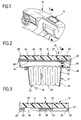
- FIGURE 1 is a perspective view of an instrument panel assembly including a cover assembly in accordance with this invention;
- FIGURE 2 is a fragmentary sectional view taken substantially along the line 2-2 of Figure 1 looking in the direction of the arrows; and
- FIGURE 3 is a fragmentary sectional view taken substantially along the line 3-3 of Figure 2 looking in the direction of the arrow.
-
- Referring now to the drawing, figures 1, 2 and 3 show an
instrument panel 10 having an airbag restraint system 12 located beneath acover assembly 14 constructed in accordance with this invention. In this particular instance, the airbag restraint system 12 is located beneath a shelf portion of the instrument panel on the passenger side of the vehicle. However thecover assembly 14 of this invention can be used on the driver side as part of the steering wheel; on either side as part of a front or passenger facing portion of the instrument panel; or as part of any other decorative panel in the passenger compartment. - The air
bag restraint system 12 includes anair bag housing 16 that encloses agas generator 18 for supplying an inflatant to anair bag 20 that is collapsed, folded and packed in thehousing 16. The foldedair bag 20 includes aninlet end 22 connected to a passage for flow of the inflatant from thegas generator 18 into the air bag. The air bag also includes anose end 24 at the opposite end of the folds that is positioned to open thecover assembly 14 of this invention when theair bag 20 inflates. - The
cover assembly 14 comprises a support orsubstrate 30 of structural plastic or other relatively stiff material that is secured beneath theinstrument panel 10 preferably by being insert molded as part of the instrument panel itself. Adoor substrate 32 of suitable structural material such as structural plastic or aluminum is attached to thepanel substrate 30 by ahinge 33 at the forward end of thedoor substrate 32 which is closest to the windshield of the vehicle. Thedoor substrate 32 closes a rectangular air bag opening 34 in thesupport 30 when thedoor substrate 32 is closed as shown in figure 2. The detached rearward end of thedoor substrate 32 that is closest to the vehicle passengers has a plurality of laterally spacedlocking tabs 36. Thelocking tabs 36 are depressed inwardly toward the airbag restraint system 12 that is located beneath thecover assembly 12. As a result of the depression, thelocking tabs 36 are integrally connected to the detached front end of thedoor substrate 32 bywebs 37 that are thinner than thedoor substrate 32. - The panel support or
substrate 30 has aslot 38 at the edge of the air bag opening 34 which confronts the detached end of thedoor substrate 32. Theslot 38 receives thelocking tabs 36 and traps thelocking tabs 36 between inner andouter lips panel support 30 that define theslot 38. Theinner lip 39 supports thelocking tabs 36 and resists movement of thedoor substrate 32 inwardly toward the airbag restraint system 12 from the closed position shown in figure 2. Theouter lip 40 retains thelocking tabs 36 and resists movement of thedoor substrate 32 outwardly from the closed position shown in figure 2. Thus thedoor substrate 32 is locked in the closed position by thelocking tabs 36 at the detached rearward end of thesubstrate 32. Thelocking tabs 36 andlips door substrate 32 when thecover assembly 14 is being manufactured and when thecover assembly 14 is subjected to normal use in a vehicle taking anticipated passenger abuse into account. - The outer surface of the panel support 30 and the hinged
door substrate 32 is bonded to a layer of suitable energy absorbing elastomeric foam, such as urethane foam that forms acushion 44 in an underlying relationship to a polymeric skin orshell 46 of vinyl or the like that forms an outer decorative surface of theinstrument panel 10. Theskin 46 may have break lines, tear lines or weakened sections that are aligned with the front end and sides of thedoor substrate 32. These break lines, tear lines or weakened sections are preferably visually imperceivable from the exterior of theinstrument panel 10 so as not to detract from its aesthetic appearance. - The
support 30 of thecover assembly 14 has a portion that holds theair bag housing 16 beneath therectangular opening 34 in spaced alignment with thedoor substrate 32. - The
cover assembly 14 operates in the following manner. When thegas generator 18 is triggered due to vehicle deceleration of a given magnitude, theair bag 20 inflates at thenose end 24 first and then progressively back toward theinlet end 22. Consequently thenose end 24 engages thedoor substrate 32 and the initial load of the inflating air bag pushes thedoor substrate 32 outwardly so that thelocking tabs 36 flex primarily at thewebs 37 and pull out of theslot 38. After thelocking tabs 36 are free ofslot 38 thedoor substrate 32 then ruptures thecushion 44 and theshell 46 at the rear and sides of thedoor 32 as thedoor substrate 32 continues outward movement by the force of the inflatingair bag 20 until thedoor substrate 32 and its covering hit the windshield. - While three laterally spaced
locking tabs 36 have been illustrated, it should be noted that the size and number oflocking tabs 36 can be varied to meet the particular needs of the materials that are used in thedoor substrate 32, thecushion 44 and theskin 46 of theinstrument panel 10. - Moreover, the thickness of the
webs 37 can be varied to meet the particular needs of the construction so that thewebs 37 are flexible enough to release thelocking tabs 36 from theslot 38 yet strong enough to keep thelock tabs 36 connected to thedoor substrate 32 when theair bag 20 is deployed. - In other words, the invention has been described in an illustrative manner, and it is to be understood that the terminology which has been used is intended to be in the nature of words of description rather than of limitation.
- Obviously, many modifications and variations of the present invention in light of the above teachings may be made. It is, therefore, to be understood that, within the scope of the appended claims, the invention may be practiced otherwise than as specifically described.
Claims (5)
- A cover assembly for concealing an air bag in a vehicle passenger compartment comprising:a support (30) that is adapted for securement beneath a decorative panel in a vehicle passenger compartment;a door substrate (32) that closes a rectangular opening (34) in the support for deployment of an air bag;the door substrate (32) having an end that is connected to the support by a hinge (33) and a detached end that is juxtaposed a confronting edge of the support when the door substrate is closed;the outer surface of the support and the hinged door substrate being bonded to an elastomeric cushion (44) formed in an underlying relationship to a polymeric skin (46) that forms an outer surface of the decorative panel; andthe detached end of the door substrate having a plurality of locking tabs (36) that are disposed in a slot (38) of the support at the confronting edge of the support to lock the door substrate in the closed position.
- The cover assembly as defined in claim 1 wherein the locking tabs (36) flex and pull out of the slot (38) when the door substrate is impacted by an inflating air bag.
- The cover assembly as defined in claim 1 wherein the locking tabs (36) are depressed so that the door substrate is substantially flush with adjacent surfaces of the support.
- The assembly as defined in claim 2 wherein the locking tabs are integrally connected to the detached end of the door substrate by webs (37) that are thinner than the door substrate.
- The cover assembly as defined in claim 2 wherein the locking tabs (36) are depressed so that the locking tabs are integrally connected to the detached end of the door substrate by thin webs and the door substrate is substantially flush with adjacent surfaces of the support.
Applications Claiming Priority (2)
| Application Number | Priority Date | Filing Date | Title |
|---|---|---|---|
| US561545 | 1995-11-22 | ||
| US08/561,545 US5673931A (en) | 1995-11-22 | 1995-11-22 | Cover assembly |
Publications (2)
| Publication Number | Publication Date |
|---|---|
| EP0775615A1 EP0775615A1 (en) | 1997-05-28 |
| EP0775615B1 true EP0775615B1 (en) | 2000-04-26 |
Family
ID=24242423
Family Applications (1)
| Application Number | Title | Priority Date | Filing Date |
|---|---|---|---|
| EP96118505A Expired - Lifetime EP0775615B1 (en) | 1995-11-22 | 1996-11-19 | Cover assembly |
Country Status (6)
| Country | Link |
|---|---|
| US (1) | US5673931A (en) |
| EP (1) | EP0775615B1 (en) |
| JP (1) | JP3865837B2 (en) |
| CA (1) | CA2189388A1 (en) |
| DE (1) | DE69607922T2 (en) |
| ES (1) | ES2146827T3 (en) |
Families Citing this family (11)
| Publication number | Priority date | Publication date | Assignee | Title |
|---|---|---|---|---|
| US6460880B1 (en) | 1995-04-21 | 2002-10-08 | Textron Automotive Company, Inc. | Method of forming a motor vehicle instrument panel with a flexibly tethered air bag deployment door |
| DE19816017A1 (en) * | 1998-04-09 | 1999-10-14 | Volkswagen Ag | Cover for an airbag arranged in a vehicle |
| US6453535B1 (en) * | 1998-06-25 | 2002-09-24 | Tip Engineering Group, Inc. | Process for manufacturing an automotive trim piece preweakened to form an air bag deployment opening |
| US6123356A (en) * | 1998-08-03 | 2000-09-26 | Textron Automotive Company | Construction and method of making air bag closure assembly |
| US6923472B1 (en) * | 1998-10-13 | 2005-08-02 | Plastic Omnium Auto Interieur Societe Anonyme | Air bag cover |
| JP2000272377A (en) * | 1999-03-25 | 2000-10-03 | Toyoda Gosei Co Ltd | Instrument panel |
| US7478827B2 (en) * | 2003-03-06 | 2009-01-20 | Ford Global Technologies, Llc | Laminated backing for containing fragments of a fractured trim cover during deployment of a passenger restraint |
| US6938564B2 (en) * | 2003-06-03 | 2005-09-06 | Amvac Chemical Corporation | Method and system for concentrating chemical granules around a planted seed |
| US20040256878A1 (en) * | 2003-06-20 | 2004-12-23 | Jsp Licenses, Inc. | Fragmentation-resistant instrument panel and method of making same |
| US20040256879A1 (en) * | 2003-06-20 | 2004-12-23 | Jsp Licenses, Inc. | Instrument panel and method of making same |
| KR20110027922A (en) * | 2009-09-11 | 2011-03-17 | 현대자동차주식회사 | Sealing structure of airbag door |
Family Cites Families (12)
| Publication number | Priority date | Publication date | Assignee | Title |
|---|---|---|---|---|
| DE2848547A1 (en) * | 1978-11-09 | 1980-05-22 | Daimler Benz Ag | COVER FOLDING DOWN FOR A FOLDED GAS PILLOW |
| US4893833A (en) * | 1988-09-08 | 1990-01-16 | Tip Engineering Group, Inc. | Closure for an air bag deployment opening |
| JP2887947B2 (en) * | 1991-06-26 | 1999-05-10 | 日産自動車株式会社 | Air bag grid mounting structure |
| DE4229379C2 (en) * | 1992-09-03 | 1996-03-28 | Daimler Benz Ag | Cover for the gas cushion of an impact protection device for vehicle occupants |
| DE4433014A1 (en) * | 1993-09-17 | 1995-03-23 | Volkswagen Ag | Carrier arrangement for receiving and securing an air bag |
| JPH07156737A (en) * | 1993-12-07 | 1995-06-20 | Inoac Corp | Structure of air bag integrated with interior side members and its manufacture |
| US5421608A (en) * | 1994-02-25 | 1995-06-06 | Davidson Textron Inc. | Trim panel having integral SIR door cover |
| DE4413416A1 (en) * | 1994-04-18 | 1995-06-29 | Daimler Benz Ag | Inflatable gas=bag cover in vehicle |
| US5433474A (en) * | 1994-05-13 | 1995-07-18 | Davidson Textron, Inc. | Air bag cover assembly |
| US5447328A (en) * | 1994-05-31 | 1995-09-05 | Davidson Textron | Trim panel having integral door cover |
| FR2721878B1 (en) * | 1994-06-30 | 1996-08-30 | Ecia Equip Composants Ind Auto | COVERING STRUCTURE OF AN INFLATABLE BAG MODULE ARRANGED IN AN ORGAN OF A MOTOR VEHICLE |
| US5466000A (en) * | 1994-11-17 | 1995-11-14 | Morton International, Inc. | Flat-lying cutter/ripper foldable into upstanding position during deployment of a vehicle airbag for detaching a deployment door from a panel |
-
1995
- 1995-11-22 US US08/561,545 patent/US5673931A/en not_active Expired - Fee Related
-
1996
- 1996-11-01 CA CA002189388A patent/CA2189388A1/en not_active Abandoned
- 1996-11-15 JP JP31852896A patent/JP3865837B2/en not_active Expired - Fee Related
- 1996-11-19 ES ES96118505T patent/ES2146827T3/en not_active Expired - Lifetime
- 1996-11-19 EP EP96118505A patent/EP0775615B1/en not_active Expired - Lifetime
- 1996-11-19 DE DE69607922T patent/DE69607922T2/en not_active Expired - Fee Related
Also Published As
| Publication number | Publication date |
|---|---|
| US5673931A (en) | 1997-10-07 |
| DE69607922D1 (en) | 2000-05-31 |
| DE69607922T2 (en) | 2000-10-05 |
| EP0775615A1 (en) | 1997-05-28 |
| CA2189388A1 (en) | 1997-05-23 |
| ES2146827T3 (en) | 2000-08-16 |
| JP3865837B2 (en) | 2007-01-10 |
| JPH09175306A (en) | 1997-07-08 |
Similar Documents
| Publication | Publication Date | Title |
|---|---|---|
| US5407225A (en) | Invisible airbag door having reinforced PVC shell | |
| US5002307A (en) | Vehicle air bag safety system | |
| US5333901A (en) | Air bag deployable instrument panel cover | |
| US5211421A (en) | Air bag cover door retainer | |
| US5431435A (en) | Door panel air bag cover | |
| JP2831055B2 (en) | Closure structure for deployment opening of airbag device | |
| US5447327A (en) | Arrangement for providing an air bag deployment opening | |
| US7690676B2 (en) | Vehicle pillar trim panel assembly | |
| EP0646501B1 (en) | Invisible seam deployment door installation with stabilized air bag deployment opening construction | |
| US5752714A (en) | Side-impact airbag assembly | |
| US5456487A (en) | Passenger air bag door | |
| US7793972B2 (en) | Front pillar trim panel with tether | |
| WO1998005536A1 (en) | Trim panel having air bag door | |
| EP0775615B1 (en) | Cover assembly | |
| JPH04185551A (en) | Air bag cover for automobile | |
| US5460402A (en) | Air bag cover door having a predetermined opening characteristic | |
| EP0710591B1 (en) | Seamless door for air bag module | |
| US5340149A (en) | Door assembly with integral tether | |
| US5492360A (en) | Tether tear strap and trim panel having same | |
| US5630613A (en) | Apparatus for aiding in the opening of an integral deployment door in a panel of an airbag assembly | |
| EP1054793A1 (en) | Peel back air bag closure assembly | |
| US5901977A (en) | Applique for concealing and retaining cover tear seam for air bag | |
| US20040188986A1 (en) | Airbag module door assembly | |
| US5626357A (en) | Passenger airbag module using an essentially unitary cover | |
| US7766372B2 (en) | Vehicle instrument panel with nonvisible airbag tear seam and deployment door and method of making the same |
Legal Events
| Date | Code | Title | Description |
|---|---|---|---|
| PUAI | Public reference made under article 153(3) epc to a published international application that has entered the european phase |
Free format text: ORIGINAL CODE: 0009012 |
|
| AK | Designated contracting states |
Kind code of ref document: A1 Designated state(s): DE ES FR GB IT NL |
|
| 17P | Request for examination filed |
Effective date: 19971107 |
|
| GRAG | Despatch of communication of intention to grant |
Free format text: ORIGINAL CODE: EPIDOS AGRA |
|
| 17Q | First examination report despatched |
Effective date: 19990423 |
|
| GRAG | Despatch of communication of intention to grant |
Free format text: ORIGINAL CODE: EPIDOS AGRA |
|
| GRAH | Despatch of communication of intention to grant a patent |
Free format text: ORIGINAL CODE: EPIDOS IGRA |
|
| GRAH | Despatch of communication of intention to grant a patent |
Free format text: ORIGINAL CODE: EPIDOS IGRA |
|
| GRAA | (expected) grant |
Free format text: ORIGINAL CODE: 0009210 |
|
| AK | Designated contracting states |
Kind code of ref document: B1 Designated state(s): DE ES FR GB IT NL |
|
| REF | Corresponds to: |
Ref document number: 69607922 Country of ref document: DE Date of ref document: 20000531 |
|
| ITF | It: translation for a ep patent filed | ||
| REG | Reference to a national code |
Ref country code: ES Ref legal event code: FG2A Ref document number: 2146827 Country of ref document: ES Kind code of ref document: T3 |
|
| ET | Fr: translation filed | ||
| PLBE | No opposition filed within time limit |
Free format text: ORIGINAL CODE: 0009261 |
|
| STAA | Information on the status of an ep patent application or granted ep patent |
Free format text: STATUS: NO OPPOSITION FILED WITHIN TIME LIMIT |
|
| 26N | No opposition filed | ||
| REG | Reference to a national code |
Ref country code: GB Ref legal event code: IF02 |
|
| PGFP | Annual fee paid to national office [announced via postgrant information from national office to epo] |
Ref country code: FR Payment date: 20021030 Year of fee payment: 7 |
|
| PGFP | Annual fee paid to national office [announced via postgrant information from national office to epo] |
Ref country code: NL Payment date: 20021031 Year of fee payment: 7 |
|
| PGFP | Annual fee paid to national office [announced via postgrant information from national office to epo] |
Ref country code: GB Payment date: 20021114 Year of fee payment: 7 |
|
| PGFP | Annual fee paid to national office [announced via postgrant information from national office to epo] |
Ref country code: ES Payment date: 20021204 Year of fee payment: 7 |
|
| PG25 | Lapsed in a contracting state [announced via postgrant information from national office to epo] |
Ref country code: GB Free format text: LAPSE BECAUSE OF NON-PAYMENT OF DUE FEES Effective date: 20031119 |
|
| PG25 | Lapsed in a contracting state [announced via postgrant information from national office to epo] |
Ref country code: ES Free format text: LAPSE BECAUSE OF NON-PAYMENT OF DUE FEES Effective date: 20031120 |
|
| PG25 | Lapsed in a contracting state [announced via postgrant information from national office to epo] |
Ref country code: NL Free format text: LAPSE BECAUSE OF NON-PAYMENT OF DUE FEES Effective date: 20040601 |
|
| GBPC | Gb: european patent ceased through non-payment of renewal fee |
Effective date: 20031119 |
|
| PG25 | Lapsed in a contracting state [announced via postgrant information from national office to epo] |
Ref country code: FR Free format text: LAPSE BECAUSE OF NON-PAYMENT OF DUE FEES Effective date: 20040730 |
|
| NLV4 | Nl: lapsed or anulled due to non-payment of the annual fee |
Effective date: 20040601 |
|
| REG | Reference to a national code |
Ref country code: FR Ref legal event code: ST |
|
| REG | Reference to a national code |
Ref country code: ES Ref legal event code: FD2A Effective date: 20031120 |
|
| PG25 | Lapsed in a contracting state [announced via postgrant information from national office to epo] |
Ref country code: IT Free format text: LAPSE BECAUSE OF NON-PAYMENT OF DUE FEES;WARNING: LAPSES OF ITALIAN PATENTS WITH EFFECTIVE DATE BEFORE 2007 MAY HAVE OCCURRED AT ANY TIME BEFORE 2007. THE CORRECT EFFECTIVE DATE MAY BE DIFFERENT FROM THE ONE RECORDED. Effective date: 20051119 |
|
| PGFP | Annual fee paid to national office [announced via postgrant information from national office to epo] |
Ref country code: DE Payment date: 20081114 Year of fee payment: 13 |
|
| PG25 | Lapsed in a contracting state [announced via postgrant information from national office to epo] |
Ref country code: DE Free format text: LAPSE BECAUSE OF NON-PAYMENT OF DUE FEES Effective date: 20100601 |