EP0775378B1 - Device for charging and transferring charge between a multiplicity of series-connected accumulators - Google Patents
Device for charging and transferring charge between a multiplicity of series-connected accumulators Download PDFInfo
- Publication number
- EP0775378B1 EP0775378B1 EP95925726A EP95925726A EP0775378B1 EP 0775378 B1 EP0775378 B1 EP 0775378B1 EP 95925726 A EP95925726 A EP 95925726A EP 95925726 A EP95925726 A EP 95925726A EP 0775378 B1 EP0775378 B1 EP 0775378B1
- Authority
- EP
- European Patent Office
- Prior art keywords
- energy storage
- triggered
- charging
- storage device
- coil
- Prior art date
- Legal status (The legal status is an assumption and is not a legal conclusion. Google has not performed a legal analysis and makes no representation as to the accuracy of the status listed.)
- Expired - Lifetime
Links
Images


Classifications
-
- H—ELECTRICITY
- H02—GENERATION; CONVERSION OR DISTRIBUTION OF ELECTRIC POWER
- H02J—CIRCUIT ARRANGEMENTS OR SYSTEMS FOR SUPPLYING OR DISTRIBUTING ELECTRIC POWER; SYSTEMS FOR STORING ELECTRIC ENERGY
- H02J7/00—Circuit arrangements for charging or depolarising batteries or for supplying loads from batteries
- H02J7/0013—Circuit arrangements for charging or depolarising batteries or for supplying loads from batteries acting upon several batteries simultaneously or sequentially
- H02J7/0014—Circuits for equalisation of charge between batteries
- H02J7/0018—Circuits for equalisation of charge between batteries using separate charge circuits
-
- Y—GENERAL TAGGING OF NEW TECHNOLOGICAL DEVELOPMENTS; GENERAL TAGGING OF CROSS-SECTIONAL TECHNOLOGIES SPANNING OVER SEVERAL SECTIONS OF THE IPC; TECHNICAL SUBJECTS COVERED BY FORMER USPC CROSS-REFERENCE ART COLLECTIONS [XRACs] AND DIGESTS
- Y02—TECHNOLOGIES OR APPLICATIONS FOR MITIGATION OR ADAPTATION AGAINST CLIMATE CHANGE
- Y02T—CLIMATE CHANGE MITIGATION TECHNOLOGIES RELATED TO TRANSPORTATION
- Y02T10/00—Road transport of goods or passengers
- Y02T10/60—Other road transportation technologies with climate change mitigation effect
- Y02T10/70—Energy storage systems for electromobility, e.g. batteries
Definitions
- the invention relates to a device for charging and Charge exchange between a variety of series and a similar energy storage forming an overall energy storage.
- Such a monitoring device is known from US-A-4,331,911 and is used to adjust the voltages of individual, series-connected Accumulators with a DC-DC converter.
- the only central converter for all accumulators is fed from the total battery and it is not able, due to aging peculiarities of individual accumulators to detect.
- DE-PS 30 31 931 is a device for extending the discharge time described by rechargeable batteries, in which the voltage states of the accumulators with a monitoring device be recorded. There will be a longer reliable discharge of the Accumulators causes the accumulator to not operate Discharge and thus when the limit voltage of the weakest is reached Cell is ended, but only when this limit voltage averages of all interconnected accumulators is reached. An extension the service life of batteries in terms of their replacement cannot be achieved with it.
- SU 1 065 959 describes a device for a battery charger known, with the overloading and charging with reverse polarity of Accumulators is prevented.
- the charging current is over a Monitored transistor circuit, which further comprises Zener diodes.
- protection circuit can neither monitor the quality of the Accumulators ensure an even longer lifespan of theirs Increase the quality of deteriorating batteries.
- a monitoring device is known from the applicant's EP 0 432 639 A2 for a large number of similar accumulators connected in series known in which an electrical with the aid of a control circuit Memory is connected in parallel to one of the accumulators, whereby the primary winding of a transformer in series with one to the Control circuit connected breakers in parallel with the poles of the Group of accumulators is connected.
- the electrical Memory each formed from the secondary winding, each over one blocking diode is connected to each accumulator.
- Via a comparison circuit is when a difference signal occurs in the control circuit a function generator connected between the batteries, the output of which is connected to the interrupter. So that can targeted supply of energy to the weakest accumulator.
- This System has the disadvantage of a multitude of small applications controlling elements that a cost and possibly a space and Represent weight factor. At the same time, in addition to the considerable effort for the selection of the respective weak or strong cell the performance range the flyback converter used is limited
- the object of the invention to create a device of the type mentioned at besides the delay in the exchange of one in its quality poorer battery with little circuitry too the charging of the energy store can be effected.
- the clock generator is preferably controlled by a sequence control circuit, which via an activation circuit for a predetermined or is switched on for a certain period of time by a switched on load.
- the device is e.g. in one device for charge balancing according to EP 0 432 639 A2 by the applicant integrable. Furthermore, it can also be used in DE 44 22 409 to be with a small number of additional components to form a combined charge balancing and charger.
- Fig. 1 shows a circuit diagram of a device for charging and Charge equalization for four batteries 1 according to a first embodiment. These can be a single group of four accumulators 1 or parts of a larger one, e.g. 10 to 12 accumulators 1 comprehensive battery bank.
- a transformer 2 which has four identical windings here 3 has, all in the same indicated by the point Sense of direction on a common core 4 in a narrow magnetic Coupling are arranged.
- a winding 3 forming an energy store is in each case one Accumulator 1 assigned, each winding 3 in series with a diode 7 is connected in parallel to the accumulator 1.
- an additional winding 13 is reversed with respect to the windings 3 Sense of winding provided in series with a parallel arrangement Combination of a switch 8 and a diode 17 to form the total battery bank is switched on.
- the windings 23 and 33 are now using the Switches 5 and 6 alternately with a duty cycle of less than 50 percent connected to the poles of the mains rectifier 10.
- the switches 5 and 6 are shown in the clock step in which the switch 5 is closed is so that the winding 23 with that of the line rectifier 10th generated intermediate circuit voltage is applied.
- Clock step then closes switch 6 while switch 5 is open, so that the winding 33 is acted upon by the intermediate circuit voltage.
- the switch 8 is open, as shown in FIG. 1. That’s how she works Device as a flow converter.
- the closing phase of switch 5 becomes a voltage in the windings 3 by the feed winding 23 induces that the diodes 7 become conductive and a current directly into the Accumulators 1 flows.
- the bigger one flows Proportion of current in the cell with the lowest Tension, so that parallel to the store a more direct Equalization of the charging voltages occurs during the charging process.
- switch 6 During the closing phase of switch 6 is switched on the feed winding 33 in the winding 13 a voltage induced so that the diode 17 becomes conductive and a current flows into the overall battery.
- Switches 5 and 6 are each with corresponding ones Outputs of a clock connected in the drawing is not shown and with the a clock frequency of preferably more than 20 kHz can be generated.
- the circuit can also have a voltage comparator, the one Switching pulse passes on to the output of the circuit when the absolute value the battery voltage within or better outside predetermined values lies. These could e.g. in the case of a lead accumulator 1 at a voltage of are greater than 2.2 volts or less than 1.95 volts. A tension of one Accumulator 1 outside of these values indicates a charging or discharging process close at which charge equalization should take place.
- a detector could also be provided with which a dynamic of the Battery voltage is detectable, which indicates rapid load changes, such as these occur when operating an electric vehicle. This could also continue Deviation of the voltage of individual accumulators 1 from a current one Average value of the overall system is provided as a trigger for the activation circuit be.
- the charge balancing circuit may e.g. also periodically, e.g. every 3 hours.
- a start pulse after one of the aforementioned Conditions are created that are checked individually or in groups can control this, for example, a monoflop that is for a predetermined Duration, e.g. half an hour, the charge exchange device turns on, or this period is characterized by a feature of the on Load determined
- the device is monitored by a logic unit, the further signals for the detection of an overcurrent in or an overtemperature of components such as transistors or windings.
- This Circuitry can also provide an output for an indication of status or control signals have, e.g. for a load shedding.
- This logic unit controls the called clock generator high clock frequency at the output of the control input the switch 8 is connected.
- the switch 8 opened and closed with a high clock frequency of a few kHz, whereby Energy taken from the total battery and the weakest single cell is fed.
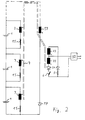
- FIG. 2 shows a circuit diagram of a further device for charging and for charge equalization for three batteries 1 according to a second embodiment.
- the same features are given the same reference symbols in all the figures Mistake.
- switches 5 and 6 alternately closed are, further switches 15, each connected in series to the windings 3 are.
- These switches 15 are in the clock step in which the switch 5 is closed is also closed and switch the windings 3 in parallel to the Accumulators 1.
- This can be the one supplied by the mains rectifier 10 Energy can be induced in the windings 3 via the feed winding 23, which emit a charging current for the individual batteries 1.
- the clock generator opens the Switch 15, so that a voltage in the winding via the feed winding 33 13 is induced and so the entire battery is charged.
- windings 3 are all in the same direction on the batteries 1 turned on, with the switches for the second clock period with open switches 15 all accumulators 1 acting together demagnetizing winding 13 is provided, which is connected via a diode 17 across the entire battery.
- the actual charge exchange takes place here in the switch-on phase in the first Cycle period instead. This can be done with a suitable choice of windings 3 and 13 also make up over 50% of a cycle because the demagnetization is rapid can be done.
- FIG. 3 shows a circuit diagram of a further device for charge equalization for two accumulators 1 shown in this section according to one third embodiment.
- Each of the accumulators 1 has two windings 3 assigned different sense of winding. These windings 3 with each with regard to their connection to the accumulator 1 different sense of winding are connected in series with a switch 15 and 16, respectively.
- the Windings 3 are arranged on a common core 4.
- each of the two becomes a little less than 50% each Accumulator 1 associated winding 3 with the accumulator 1 in parallel connected, wherein all accumulators are virtually connected in parallel, so that in every step there is a charge balance and a current in the weakest accumulator 1 flows
- the device has the feed windings 23 and 33 on the common core 4, which in one to the other embodiments are connected in an analogous manner to the mains rectifier 10.
- switches 5 and 15 or 6 and 16 are now closed together or opened.
- the switches 5 and 15 and the switches 6 and 16 are each operated synchronously. So that when switch 5 is closed on the Feed winding 23 induces a voltage in the windings 3, which over the Switch 15 are connected in parallel to the accumulators 1.
Abstract
Description
Die Erfindung betrifft eine Vorrichtung zur Aufladung und zum Ladungsaustausch zwischen einer Vielzahl von in Reihe geschalteten und einen Gesamtenergiespeicher bildenden, gleichartigen Energiespeichern.The invention relates to a device for charging and Charge exchange between a variety of series and a similar energy storage forming an overall energy storage.
Eine solche Überwachungsvorrichtung ist aus der US-A-4 331 911 bekannt und dient zum Angleichen von Spannungen einzelner, in Reihe geschalteter Akkumulatoren mit einem DC-DC-Wandler. Der einzige zentrale Wandler für alle Akkumulatoren wird aus der Gesamtbatterie gespeist und er ist nicht fähig, durch Alterung auftretende Besonderheiten einzelner Akkumulatoren zu detektieren.Such a monitoring device is known from US-A-4,331,911 and is used to adjust the voltages of individual, series-connected Accumulators with a DC-DC converter. The only central converter for all accumulators is fed from the total battery and it is not able, due to aging peculiarities of individual accumulators to detect.
Bis ein solcher, in seiner Speicherungs- und Ladungsqualität absinkender Akkumulator von der Überwachungseinrichtung für Akkumulatoren erkannt wird, führt sein Fehlverhalten zu einer Kette von Reaktionen in der Gruppe der Akkumulatoren, was zu einer Degradation auch der anderen Akkumulatoren führt.Until such a time, in terms of storage and load quality Accumulator from the monitoring device for accumulators is recognized, his misconduct leads to a chain of reactions in the group of accumulators, which also leads to a degradation leads to other accumulators.
In der DE-PS 30 31 931 ist eine Vorrichtung zur Verlängerung der Entladungsdauer von wiederaufladbaren Akkumulatoren beschrieben, bei der mit einer Überwachungseinrichtung die Spannungszustände der Akkumulatoren erfaßt werden. Es wird eine längere betriebssichere Entladung der Akkumulatoren dadurch bewirkt, daß der Akkumulatorbetrieb nicht bei Entladung und damit bei Erreichen einer Grenzspannung der schwächsten Zelle beendet wird, sondern erst, wenn diese Grenzspannung im Mittel aller zusammengeschalteten Akkumulatoren erreicht wird. Eine Verlängerung der Standzeit von Akkumulatoren im Hinblick auf ihre Auswechslung läßt sich damit nicht erreichen.In DE-PS 30 31 931 is a device for extending the discharge time described by rechargeable batteries, in which the voltage states of the accumulators with a monitoring device be recorded. There will be a longer reliable discharge of the Accumulators causes the accumulator to not operate Discharge and thus when the limit voltage of the weakest is reached Cell is ended, but only when this limit voltage averages of all interconnected accumulators is reached. An extension the service life of batteries in terms of their replacement cannot be achieved with it.
Aus der SU 1 065 959 ist eine Vorrichtung für ein Akkumulatorladegerät bekannt, mit der das Überladen und das Laden mit Falschpolung von Akkumulatoren verhindert wird. Dabei wird der Ladestrom über eine Transistorschaltung überwacht, die weiterhin Zenerdioden umfaßt. Diese Schutzschaltung kann jedoch weder die Überwachung der Qualität der Akkumulatoren gewährleisten, noch eine längere Standzeit von in ihrer Qualität schlechter werdenden Akkumulatoren bewirken.SU 1 065 959 describes a device for a battery charger known, with the overloading and charging with reverse polarity of Accumulators is prevented. The charging current is over a Monitored transistor circuit, which further comprises Zener diodes. This However, protection circuit can neither monitor the quality of the Accumulators ensure an even longer lifespan of theirs Increase the quality of deteriorating batteries.
Aus der EP 0 432 639 A2 der Anmelderin ist eine Überwachungseinrichtung für eine Vielzahl von in Reihe geschalteten, gleichartigen Akkumulatoren bekannt, bei der mit Hilfe einer Steuerschaltung ein elektrischer Speicher parallel zu einem der Akkumulatoren zugeschaltet wird, wobei die Primärwicklung eines Transformators in Reihe mit einem an die Steuerschaltung angeschlossenen Unterbrecher parallel zu den Polen der Gruppe von Akkumulatoren verbunden ist. Dabei wird der elektrische Speicher jeweils aus der Sekundärwicklung gebildet, die über jeweils eine sperrende Diode mit jedem Akkumulator verbunden ist. Über eine Vergleichsschaltung wird bei Auftreten eines Differenzsignals in der Steuerschaltung zwischen den Akkumulatoren ein Funktionsgenerator angeschaltet, dessen Ausgang mit dem Unterbrecher verbunden ist. Damit kann gezielt dem schwächsten Akkumulator Energie zugeführt werden. Diese Anlage weist für kleine Anwendungen den Nachteil einer Vielzahl von steuernden Elementen auf, die einen Kosten- und ggf. einen Raum- und Gewichtsfaktor darstellen. Zugleich ist neben dem erheblichen Aufwand für die Selektion der jeweiligen schwachen oder starken Zelle der Leistungsbereich der jeweils eingesetzten Sperrwandler nach oben begrenztA monitoring device is known from the applicant's EP 0 432 639 A2 for a large number of similar accumulators connected in series known in which an electrical with the aid of a control circuit Memory is connected in parallel to one of the accumulators, whereby the primary winding of a transformer in series with one to the Control circuit connected breakers in parallel with the poles of the Group of accumulators is connected. The electrical Memory each formed from the secondary winding, each over one blocking diode is connected to each accumulator. Via a comparison circuit is when a difference signal occurs in the control circuit a function generator connected between the batteries, the output of which is connected to the interrupter. So that can targeted supply of energy to the weakest accumulator. This System has the disadvantage of a multitude of small applications controlling elements that a cost and possibly a space and Represent weight factor. At the same time, in addition to the considerable effort for the selection of the respective weak or strong cell the performance range the flyback converter used is limited
Alle diese Vorrichtungen weisen den Nachteil auf, daß zur Aufladung der Energiespeicher, bei denen es sich zB. um Batteriebänke eines Elektrofahrzeugs handeln kann, ein externes Ladegerät vorgesehen sein muß, welches wiederum in einem solchen Fahrzeug Platz einnimmt und zusätzliches Gewicht ausmacht.All these devices have the disadvantage that to charge the Energy storage, for example. around battery banks of an electric vehicle can act, an external charger must be provided, which in turn takes up space in such a vehicle and additional Weight.
Ausgehend von diesem Stand der Technik liegt der Erfindung die Aufgabe zugrunde, eine Vorrichtung der eingangs genannten Art zu schaffen, bei dem neben der Verzögerung des Austausches eines in seiner Qualität schlechteren Akkumulators mit einem geringen Schaltungsaufwand auch die Aufladung der Energiespeicher bewirkt werden kann.Starting from this prior art, the object of the invention to create a device of the type mentioned at besides the delay in the exchange of one in its quality poorer battery with little circuitry too the charging of the energy store can be effected.
Diese Aufgabe wird erfindungsgemäß mit einer Vorrichtung gemäß den
Merkmalen des Anspruchs 1 bzw. den Merkmalen des Anspruchs 2 gelöst.This object is achieved with a device according to the
Features of
Vorzugsweise wird der Taktgeber von einer Ablaufsteuerschaltung angesteuert, die über eine Aktivierschaltung für einen vorbestimmbaren oder von einer angeschalteten Last bestimmten Zeitraum eingeschaltet ist.The clock generator is preferably controlled by a sequence control circuit, which via an activation circuit for a predetermined or is switched on for a certain period of time by a switched on load.
Nachfolgend werden mehrere Ausführungsbeispiele der Erfindung anhand der Zeichnung näher erläutert. Es zeigen:
- Fig. 1
- ein Schaltbild einer Vorrichtung zur Aufladung und zum Ladungsausgleich für vier Akkumulatoren gemäß einem ersten Ausführungsbeispiel,
- Fig. 2
- ein Schaltbild einer weiteren Vorrichtung zur Aufladung und zum Ladungsausgleich für drei Akkumulatoren gemäß einem zweiten Ausführungsbeispiel, und
- Fig. 3
- ein Schaltbild einer weiteren Vorrichtung zur Aufladung und zum Ladungsausgleich für zwei Akkumulatoren gemäß einem dritten Ausführungsbeispiel.
- Fig. 1
- 1 shows a circuit diagram of a device for charging and for charge equalization for four batteries according to a first exemplary embodiment,
- Fig. 2
- 2 shows a circuit diagram of a further device for charging and for charge equalization for three batteries according to a second exemplary embodiment, and
- Fig. 3
- a circuit diagram of another device for charging and charge equalization for two batteries according to a third embodiment.
Es sind natürlich eine Vielzahl von Realisierungsmöglichkeiten von Schaltungen zur Durchführung des Verfahrens möglich, von denen in der Folge mehrere dargestellt werden. Die Vorrichtung ist z.B. bei einer Vorrichtung zum Ladungsausgleich gemäß der EP 0 432 639 A2 der Anmelderin integrierbar. Weiterhin kann sie auch bei der DE 44 22 409 eingesetzt werden, um mit einer geringen Anzahl von zusätzlichen Bauteilen ein kombiniertes Ladungsausgleich- und Ladegerät zu bilden.There are, of course, a large number of circuit implementation options possible to carry out the procedure, of which in the following several are shown. The device is e.g. in one device for charge balancing according to EP 0 432 639 A2 by the applicant integrable. Furthermore, it can also be used in DE 44 22 409 to be with a small number of additional components to form a combined charge balancing and charger.
Die Fig. 1 zeigt ein Schaltbild einer Vorrichtung zur Aufladung und zum
Ladungsausgleich für vier Akkumulatoren 1 gemäß einem ersten Ausführungsbeispiel.
Diese können eine einzelne Gruppe von vier Akkumulatoren
1 bilden oder Teile einer größeren, z.B. 10 bis 12 Akkumulatoren 1
umfassenden Batteriebank sein.Fig. 1 shows a circuit diagram of a device for charging and
Charge equalization for four
Es ist ein Transformator 2 vorgesehen, der über hier vier gleiche Wicklungen
3 verfügt, die alle im gleichen durch den Punkt angedeuteten
Richtungssinn auf einem gemeinsamen Kern 4 in enger magnetischer
Kopplung angeordnet sind. A
Dabei ist hier jeweils eine einen Energiespeicher bildende Wicklung 3 einem
Akkumulator 1 zugeordnet, wobei jede Wicklung 3 in Reihe mit einer Diode 7
zu dem Akkumulator 1 parallel geschaltet ist.In this case, a
Weiterhin ist eine Zusatzwicklung 13 mit gegenüber den Wicklungen 3 umgekehrtem
Wicklungssinn vorgesehen, die in Reihe mit einer parallel angeordneten
Kombination eines Schalters 8 und einer Diode 17 zu der Gesamtbatteriebank
zugeschaltet ist.Furthermore, an
Darüberhinaus sind auf dem Kern 4 zwei weitere Speisewicklungen 23 und 33
mit gleichem Wicklungssinn vorgesehen, die über einen Mittelabgriff 9 an dem
Netzausgang positiver Spannung eines Netzgleichrichters 10 angeschlossen sind.
Die anderen Wicklungsenden der Speisewicklungen 23 und 33 sind jeweils in
Reihe mit einer Diode 27 und Schaltern 5 bzw. 6 an dem Netzausgang negativer
Spannung des Netzgleichrichters 10 angeschlossen. Der Netzgleichrichter 10 wird
z.B. aus dem üblichen Wechselspannungsnetz 11 gespeist und erzeugt sekundärseitig
eine Zwischenkreisspannung.In addition, there are two
In der Ladephase werden die Wicklungen 23 und 33 nun mit Hilfe von den
Schaltern 5 und 6 mit einem Tastverhältnis von weniger als 50 Prozent abwechselnd
mit den Polen des Netzgleichrichters 10 verbunden. Die Schalter 5
und 6 sind in demjenigen Taktschritt dargestellt, in dem der Schalter 5 geschlossen
ist, so daß die Wicklung 23 mit der von dem Netzgleichrichter 10
erzeugten Zwischenkreisspannung beaufschlagt ist. Im nächsten, nicht dargestellten
Taktschritt schließt dann der Schalter 6, während der Schalter 5 offen ist, so
daß die Wicklung 33 von der Zwischenkreisspannung beaufschlagt wird.In the loading phase, the
Der Schalter 8 ist dabei, wie in der Fig. 1 dargestellt, offen. Damit arbeitet die
Vorrichtung als Durchflußwandler. Während der Schließphase von Schalter 5
wird durch die Speisewicklung 23 in den Wicklungen 3 eine Spannung derart
induziert, daß die Dioden 7 leitend werden und ein Strom jeweils direkt in die
Akkumulatoren 1 fließt. Dabei fließt der größere
Anteil des Stromes in die Zelle mit der niedrigsten
Spannung, so daß parallel zu dem Laden ein direkter
Ausgleich der Ladespannungen beim Ladevorgang auftritt.The
Während der Schließphase von Schalter 6 wird durch
die Speisewicklung 33 in der Wicklung 13 eine Spannung
induziert, so daß die Diode 17 leitend wird
und ein Strom in die Gesamtbatterie fließt.During the closing phase of
Die Schalter 5 und 6 sind jeweils mit entsprechenden
Ausgängen eines Taktgebers verbunden, der in
der Zeichnung nicht dargestellt ist und mit dem
eine Taktfrequenz von vorzugsweise mehr als 20 kHz
erzeugbar ist.
Es wird in zwei Taktschritten einmal bei geschlossenem
Schalter 6 die Gesamtbatterie geladen und bei
geschlossenem Schalter 5 über die Wicklungen 3
jeder einzelne Akkumulator 1 aufgeladen. Bei entsprechender
Dimensionierung der genannten Wicklungen
wird ungefähr die eine Hälfte der Energie direkt
in die Gesamtbatterie eingespeist und die
andere Hälfte fließt über die Wicklungen 3 und die
Dioden 7 in die einzelnen Akkumulatoren 1.It is done in two steps, once when closed
Durch die enge magnetische Kopplung wird in allen
Wicklungen 3, also insbesondere in den hier dargestellten
vier Wicklungen 3 die gleiche Spannung
induziert. Weist nun ein Akkumulator 1 durch Alterung
oder sonstige Einflüsse eine niedrigere Spannung
aus, so fließt direkt ein entsprechender Strom
in diese Zelle. Due to the close magnetic coupling in all
Wenn der Aufladungsvorgang abgeschlossen ist, sind
die Schalter 5 und 6 offen und der Netzgleichrichter
10 wird vom Netz getrennt. Dann wird mit Hilfe
einer Ablaufsteuerung die Vorrichtung als Sperrwandler
betrieben. Dabei ist eine Aktivierschaltung
vorgesehen, die durch eine Vielzahl von Ereignissen
je nach Einsatzzweck ausgelöst werden kann. Dabei
kann es sich um einen einfachen
manuellen Ein-/Aus-Schalter handeln, der z.B. durch das Äquivalent eines
Zündschlosses bei einem akkumulatorgetriebenen Fahrzeug gebildet sein kann.When the charging process is
Die Schaltung kann auch einen Spannungskomparator aufweisen, der einen
Schaltimpuls an den Ausgang der Schaltung weitergibt, wenn der Absolutwert
der Batteriespannung innerhalb oder besser außerhalh vorbestimmter Werte
liegt. Diese könnten z.B. bei einem Blei-Akkumulator 1 bei einer Spannung von
größer als 2,2 Volt oder kleiner als 1,95 Volt liegen. Eine Spannung eines
Akkumulators 1 außerhalb dieser Werte läßt auf einen Ladungs- oder Entladungsvorgang
schließen, bei dem der Ladungsausgleich vonstatten gehen sollte.The circuit can also have a voltage comparator, the one
Switching pulse passes on to the output of the circuit when the absolute value
the battery voltage within or better outside predetermined values
lies. These could e.g. in the case of a
Es könnte auch ein Detektor vorgesehen sein, mit dem eine Dynamik des
Batteriespannung nachweisbar ist, die auf schnelle Lastwechsel hindeutet, wie
diese beim Betrieb eines Elektrofahrzeugs auftreten. Weiterhin könnte auch das
Abweichen der Spannung einzelner Akkumulatoren 1 von einem momentanen
Mittelwert des Gesamtsystems als Auslöser für die Aktivierschaltung vorgesehen
sein. Schließlich kann die Schaltung zum Ladungsausgleich z.B. auch periodisch,
z.B. alle 3 Stunden, anlaufen.A detector could also be provided with which a dynamic of the
Battery voltage is detectable, which indicates rapid load changes, such as
these occur when operating an electric vehicle. This could also continue
Deviation of the voltage of
Wenn die Aktivierschaltung einen Startimpuls nach einer der vorgenannten
Bedingungen erzeugt, die einzeln aber auch zu mehreren geprüft werden
können, steuert dieser beispielsweise einen Monoflop an, der für eine vorbestimmte
Zeitdauer, z.B. eine halbe Stunde, die Vorrichtung zum Ladungsaustausch
anstellt, oder diese Zeitdauer wird durch ein Merkmal der angeschalteten
Last festgelegt Die Vorrichtung wird durch eine Logikeinheit überwacht,
der weitere Signale zur Detektion eines Überstromes in oder einer Übertemperatur
von Bauteilen wie Transistoren oder Wicklungen zugeführt werden. Diese
Schaltung kann auch einen Ausgang für eine Anzeige für Status- oder Steuersignale
aufweisen, z.B. für einen Lastabwurf. Diese Logikeinheit steuert den
genannten Taktgenerator hoher Taktfrequenz an, an dessen Ausgang der Steuereingang
des Schalters 8 angeschlossen wird. If the activation circuit a start pulse after one of the aforementioned
Conditions are created that are checked individually or in groups
can control this, for example, a monoflop that is for a predetermined
Duration, e.g. half an hour, the charge exchange device
turns on, or this period is characterized by a feature of the on
Load determined The device is monitored by a logic unit,
the further signals for the detection of an overcurrent in or an overtemperature
of components such as transistors or windings. This
Circuitry can also provide an output for an indication of status or control signals
have, e.g. for a load shedding. This logic unit controls the
called clock generator high clock frequency at the output of the control input
the
Bei einer Funktion der Vorrichtung zum Ladungsausgleich wird der Schalter 8
mit hoher Taktfrequenz von einigen kHz geöffnet und geschlossen, wodurch
Energie aus der Gesamtbatterie entnommen und der schwächsten Einzelzelle
zugeführt wird.When the charge balancing device functions, the
Die Fig. 2 zeigt ein Schaltbild einer weiteren Vorrichtung zur Aufladung und
zum Ladungsausgleich für drei Akkumulatoren 1 gemäß einem zweiten Ausführungsbeispiel.
Gleiche Merkmale sind in allen Fig. mit gleichen Bezugszeichen
versehen.2 shows a circuit diagram of a further device for charging and
for charge equalization for three
Bei dieser Schaltung beaufschlagt das Steuersignal des Taktgebers, mit dessen
Hilfe in den zwei Taktschritten abwechselnd die Schalter 5 und 6 geschlossen
werden, weitere Schalter 15, die jeweils in Reihe zu den Wicklungen 3 geschaltet
sind. Diese Schalter 15 sind in dem Taktschritt, in dem der Schalter 5 geschlossen
ist, ebenfalls geschlossen und schalten die Wicklungen 3 parallel zu den
Akkumulatoren 1. Damit kann jeweils die von dem Netzgleichrichter 10 gelieferte
Energie über die Speisewicklung 23 in den Wicklungen 3 induziert werden,
die einen Ladestrom für die einzelnen Akkumulatoren 1 abgeben.In this circuit, the control signal of the clock generator is applied
Help in the two cycle steps, switches 5 and 6 alternately closed
are, further switches 15, each connected in series to the
Wenn dagegen der Schalter 6 geschlossen ist, so öffnet der Taktgeber die
Schalter 15, so daß über die Speisewicklung 33 eine Spannung in der Wicklung
13 induziert wird und so die Gesamtbatterie aufgeladen wird.If, however, the
Die Vorrichtung gemäß Fig. 2 arbeitet dann als Schaltung zum Ladungsausgleich,
wenn beide Schalter 5 und 6 geöffnet sind und mit Hilfe desselben oder
eines weiteren Taktgebers nur die Schalter 15 geöffnet und geschlossen werden.2 then works as a circuit for charge equalization,
if both
Die Wicklungen 3 sind alle im gleichen Richtungssinn an die Akkumulatoren 1
angeschaltet, wobei für die zweite Taktperiode mit offenen Schaltern 15 die für
alle Akkumulatoren 1 gemeinsam wirkende Entmagnetisierungswicklung 13
vorgesehen ist, die über eine Diode 17 über die Gesamtbatterie geschaltet wird. The
Der eigentliche Ladungsaustausch findet hier in der Einschaltphase in der ersten
Taktperiode statt. Diese kann hei geeigneter Wahl der Wicklungen 3 und 13
auch über 50% eines Taktes ausmachen, da die Entmagnetisierung rasch
erfolgen kann.The actual charge exchange takes place here in the switch-on phase in the first
Cycle period instead. This can be done with a suitable choice of
Die Fig. 3 zeigt ein Schaltbild einer weiteren Vorrichtung zum Ladungsausgleich
für in diesem Ausschnitt dargestellte zwei Akkumulatoren 1 gemäß einem
dritten Ausführungsbeispiel. Es sind zwei in Reihe geschaltete Akkumulatoren 1
dargestellt, die Teil einer eine Vielzahl von Akkumulatoren beinhaltenden
Batteriebank sind. Jedem der Akkumulatoren 1 sind zwei Wicklungen 3 mit
unterschiedlichem Wicklungssinn zugeordnet. Diese Wicklungen 3 mit jeweils
bezüglich ihrer Anschaltung an den Akkumulator 1 unterschiedlichem Wicklungssinn
sind in Reihe mit jeweils einem Schalter 15 bzw. 16 verbunden. Die
Wicklungen 3 sind auf einem gemeinsamen Kern 4 angeordnet.3 shows a circuit diagram of a further device for charge equalization
for two
Durch das aufeinanderfolgende Schließen der Schalter 15 bzw. 16 in einem Tastverhältnis
von z.B. etwas weniger als 50% wird jeweils jede der beiden einem
Akkumulator 1 zugeordnete Wicklung 3 mit dem Akkumulator 1 parallel
verbunden, wobei jeweils alle Akkqmulatoren virtuell parallel geschaltet sind, so
daß in jedem Schritt ein Ladungsausgleich stattfindet und ein Strom in den
schwächsten Akkumulator 1 fließtBy the successive closing of the
Weiterhin verfügt die Vorrichtung über die Speisewicklungen 23 und 33 auf dem
gemeinsamen Kern 4, die in einer zu den anderen Ausführungsbeispielen
analogen Weise an dem Netzgleichrichter 10 angeschlossen sind. Bei einem
Ladebetrieb sind nun die Schalter 5 und 15 bzw. 6 und 16 gemeinsam geschlossen
oder geöffnet. Die Schalter 5 und 15 bzw. die Schalter 6 und 16 werden
jeweils synchron betrieben. Damit wird bei geschlossenem Schalter 5 über die
Speisewicklung 23 eine Spannung in den Wicklungen 3 induziert, die über die
Schalter 15 gerade zu den Akkumulatoren 1 parallel geschaltet sind.Furthermore, the device has the
Claims (3)
- Device for charging and for making a charge exchange between a large number of energy storage devices (1) of the same kind, connected in series and forming a total energy storage device, on which device one coil (3) of a transformer (2) which is capable of storing energy lies as an electrical storage device parallel to each energy storage device via a switch (15) which may be triggered or a diode (7), a charging or feed coil (23, 33) is provided, a further coil (13) is connected in parallel via a further switch (8) which may be triggered or a diode (17) to the overall energy storage device, and on which, during the charging operation, the feed coil (23, 33) receives a voltage with polarity alternating in cycles by means of feed coil switches which may be triggered(5, 6), such that, in the first cycle step, each energy storage device (1) is charged via the coils (3), and in the second cycle step the total energy storage device is charged via the additional coil (13), and on which, furthermore, during the charge exchange operation, the feed coil (23, 33) is switched off and either the coils (3) are charged in one cycle step by means of the additional coil (13) from the total energy storage device, and in a second cycle step release their energy to the energy storage devices associated with them, or by means of the interpolation of a number of coils (3) in one cycle step an inductive parallel connection of the same is effected, demagnetisation of the transformer taking place in the second cycle step via the additional coil (13) and a clock unit being provided to trigger all the switches which may be triggered (5, 6, 8, 15).
- Device for charging and for making a charge exchange between a large number of energy storage devices (1) of the same kind which are connected in series and form a total energy storage device, on which two coils (3), with opposite polarity, of a transformer lie parallel to each energy storage device (1) via associated switches (15, 16) which may be triggered and a charging or feed coil (23, 33) is provided on which, during the charging operation, the feed coil (23, 33) receives a voltage with polarity alternating in cycles by means of feed coil switches (5, 6) which may be triggered and the energy storage devices (1) are charged via the coils (3) by synchronous alternative triggering of the switches (15, 16) associated with them which may be triggered, and, during the charging exchange operation, the feed coil (23, 33) is switched off and the energy storage devices (1) are connected inductively in parallel by synchronous alternative triggering of the switches (15, 16) associated with them which may be triggered and associated with them and a clock unit is provided to trigger all the switches (5, 6, 15, 16) which may be triggered.
- Device according to one of claims 1 or 2,
characterised in that
the clock unit may be triggered by a sequencing circuit which may be switched on by an activating circuit for a period of time which may be pre-determined or is determined by a connected load.
Applications Claiming Priority (3)
| Application Number | Priority Date | Filing Date | Title |
|---|---|---|---|
| DE4428769A DE4428769C1 (en) | 1994-08-13 | 1994-08-13 | Device for charging and / or for exchanging charges between a plurality of energy stores connected in series |
| DE4428769 | 1994-08-13 | ||
| PCT/DE1995/000975 WO1996005643A1 (en) | 1994-08-13 | 1995-07-21 | Method and device for charging and/or transferring charge between a multiplicity of series-connected accumulators |
Publications (2)
| Publication Number | Publication Date |
|---|---|
| EP0775378A1 EP0775378A1 (en) | 1997-05-28 |
| EP0775378B1 true EP0775378B1 (en) | 1998-11-11 |
Family
ID=6525647
Family Applications (1)
| Application Number | Title | Priority Date | Filing Date |
|---|---|---|---|
| EP95925726A Expired - Lifetime EP0775378B1 (en) | 1994-08-13 | 1995-07-21 | Device for charging and transferring charge between a multiplicity of series-connected accumulators |
Country Status (4)
| Country | Link |
|---|---|
| US (1) | US5767660A (en) |
| EP (1) | EP0775378B1 (en) |
| DE (2) | DE4428769C1 (en) |
| WO (1) | WO1996005643A1 (en) |
Families Citing this family (34)
| Publication number | Priority date | Publication date | Assignee | Title |
|---|---|---|---|---|
| SE507339C2 (en) * | 1995-10-31 | 1998-05-18 | Xicon Battery Electronics Ab | Battery level equalization system in batteries consisting of series connected battery cells or battery blocks |
| AU1271599A (en) * | 1997-10-20 | 1999-05-10 | Usar Systems Inc. | Improved voltaic pile with charge equalizing system |
| US6169334B1 (en) | 1998-10-27 | 2001-01-02 | Capstone Turbine Corporation | Command and control system and method for multiple turbogenerators |
| KR20010006576A (en) * | 1999-01-18 | 2001-01-26 | 가나이 쓰도무 | Apparatus for charging and discharging electric power accumulating mean and method for manufacturing electric power accumulating mean using the same |
| JP3280635B2 (en) * | 1999-04-21 | 2002-05-13 | 長野日本無線株式会社 | Energy transfer device and power storage system |
| JP3280641B2 (en) * | 1999-09-08 | 2002-05-13 | 長野日本無線株式会社 | Energy transfer device |
| JP3280642B2 (en) * | 1999-09-08 | 2002-05-13 | 長野日本無線株式会社 | Power storage module |
| EP1141879B1 (en) * | 1999-10-22 | 2013-08-07 | Nxp B.V. | Data carrier with load modulation means and with improved power supply in the process of load modulation |
| JP2001258175A (en) * | 2000-03-14 | 2001-09-21 | Hitachi Ltd | System and method for utilizing secondary battery for storing power |
| US6410992B1 (en) | 2000-08-23 | 2002-06-25 | Capstone Turbine Corporation | System and method for dual mode control of a turbogenerator/motor |
| JP3364836B2 (en) * | 2000-10-19 | 2003-01-08 | 富士重工業株式会社 | Voltage equalizer device and method thereof |
| JP3630303B2 (en) * | 2000-11-21 | 2005-03-16 | 長野日本無線株式会社 | Voltage equalization device for storage element |
| US8026637B2 (en) * | 2001-01-24 | 2011-09-27 | Cochlear Limited | Power supply having an auxiliary power cell |
| AUPR269301A0 (en) * | 2001-01-24 | 2001-02-22 | Cochlear Limited | Power supply for a cochlear implant |
| AU2003251306A1 (en) * | 2002-05-20 | 2003-12-12 | Good Ideas Llc | Ultracapacitor balancing circuit |
| DE10312362A1 (en) * | 2003-03-20 | 2004-09-30 | Andreas Klasen | Charging-balancing system for re-charging accumulators arranged in rows as individual cells or blocks carries out capacitive balancing during charging and discharging |
| US20050077879A1 (en) * | 2003-10-14 | 2005-04-14 | Near Timothy Paul | Energy transfer device for series connected energy source and storage devices |
| JP3795499B2 (en) * | 2003-12-26 | 2006-07-12 | 富士重工業株式会社 | Voltage equalization device for storage element |
| US7170764B2 (en) * | 2004-02-24 | 2007-01-30 | Vlt, Inc. | Adaptively configured voltage transformation module array |
| US7212419B2 (en) * | 2004-02-24 | 2007-05-01 | Vlt, Inc. | Adaptively configured and autoranging voltage transformation module arrays |
| US7548441B2 (en) | 2004-02-24 | 2009-06-16 | Vlt, Inc. | Universal AC adapter |
| US7782639B2 (en) * | 2004-02-24 | 2010-08-24 | Vlt, Inc. | Adaptively configured and autoranging power converter arrays |
| US7561446B1 (en) | 2005-09-15 | 2009-07-14 | Vlt, Inc. | Double-clamped ZVS buck-boost power converter |
| US7408795B2 (en) * | 2004-02-24 | 2008-08-05 | Vlt, Inc. | Energy storage and hold-up method and apparatus for high density power conversion |
| JP2006246646A (en) * | 2005-03-04 | 2006-09-14 | Yazaki Corp | Equalization method and its device |
| DE102008023292A1 (en) * | 2008-05-13 | 2009-12-03 | Clean Mobile Ag | Electrical drive system for bicycle, has secondary switches provided for parallel connection of secondary coils with respective batteries, where secondary switches are switched independent of each other |
| DE102008023291A1 (en) * | 2008-05-13 | 2009-11-19 | Clean Mobile Ag | Electrical light vehicle i.e. bicycle, has secondary switches for parallel switching of secondary coils with accumulators, respectively where secondary switches are switchable independent of each other |
| US20100308765A1 (en) | 2009-04-01 | 2010-12-09 | Eaglepicher Technologies, Llc | Hybrid energy storage system, renewable energy system including the storage system, and method of using same |
| US8267123B2 (en) * | 2009-06-29 | 2012-09-18 | Emerson Process Management, Valve Automation Inc. | Methods and apparatus to charge accumulator apparatus |
| ES2788098T3 (en) * | 2009-12-14 | 2020-10-20 | Leach Int Corporation | Systems and Methods for Balancing Multi-Cell Batteries |
| DE102011014925A1 (en) * | 2011-03-24 | 2012-09-27 | Jungheinrich Aktiengesellschaft | Device for active balancing of voltage sources |
| DE102011014924A1 (en) * | 2011-03-24 | 2012-09-27 | Jungheinrich Aktiengesellschaft | Industrial truck with an electric drive |
| DE102012214446A1 (en) | 2012-08-14 | 2014-02-20 | Robert Bosch Gmbh | Switchable energy storage device and method for operating a switchable energy storage device |
| DE202018100962U1 (en) * | 2018-02-21 | 2018-03-02 | Igus Gmbh | Monitoring system for energy guiding chains |
Family Cites Families (8)
| Publication number | Priority date | Publication date | Assignee | Title |
|---|---|---|---|---|
| US4079303A (en) * | 1976-07-28 | 1978-03-14 | The United States Of America As Represented By The United States Department Of Energy | Charging system and method for multicell storage batteries |
| US4331911A (en) * | 1978-05-22 | 1982-05-25 | Park Robert H | Method of equalizing the voltages of the individual cells of storage batteries |
| DE3031887C2 (en) * | 1980-06-28 | 1984-09-20 | Lucas Industries Ltd., Birmingham, West Midlands | Procedure for charging a traction battery |
| SU1065959A1 (en) * | 1982-05-24 | 1984-01-07 | Предприятие П/Я А-1070 | Automatic device for charging storage battery |
| US5003244A (en) * | 1989-05-09 | 1991-03-26 | Digital Equipment Corporation | Battery charger for charging a plurality of batteries |
| DE3940928C1 (en) * | 1989-12-12 | 1991-07-11 | Fraunhofer-Gesellschaft Zur Foerderung Der Angewandten Forschung Ev, 8000 Muenchen, De | |
| US5633575A (en) * | 1994-03-31 | 1997-05-27 | Gali; Carl E. | Battery reclaimer and charger |
| US5646504A (en) * | 1994-04-15 | 1997-07-08 | Feldstein; Robert S. | Magnetically balanced multi-output battery charging system |
-
1994
- 1994-08-13 DE DE4428769A patent/DE4428769C1/en not_active Expired - Fee Related
-
1995
- 1995-07-21 DE DE59504232T patent/DE59504232D1/en not_active Expired - Fee Related
- 1995-07-21 EP EP95925726A patent/EP0775378B1/en not_active Expired - Lifetime
- 1995-07-21 WO PCT/DE1995/000975 patent/WO1996005643A1/en active IP Right Grant
- 1995-07-21 US US08/776,734 patent/US5767660A/en not_active Expired - Fee Related
Also Published As
| Publication number | Publication date |
|---|---|
| US5767660A (en) | 1998-06-16 |
| EP0775378A1 (en) | 1997-05-28 |
| DE4428769C1 (en) | 1996-05-02 |
| DE59504232D1 (en) | 1998-12-17 |
| WO1996005643A1 (en) | 1996-02-22 |
Similar Documents
| Publication | Publication Date | Title |
|---|---|---|
| EP0775378B1 (en) | Device for charging and transferring charge between a multiplicity of series-connected accumulators | |
| EP0767983B1 (en) | Process and device for charge exchange between a plurality of series-connected energy stores or converters | |
| EP0772785B1 (en) | Charge exchanging device among a plurality of energy accumulators or converters interconnected in series | |
| DE3940928C1 (en) | ||
| DE102008021090B4 (en) | Circuit arrangement and method for exchanging electrical charge between accumulators in an accumulator arrangement | |
| EP1711990B1 (en) | Device and method for equalising the charge of serially connected capacitors belonging to a double layer capacitor | |
| EP0432640B1 (en) | Monitoring device for accumulators | |
| DE3815001A1 (en) | DEVICE FOR CHARGING ACCUMULATORS | |
| DE102009028973A1 (en) | DC / DC converter circuit and battery system | |
| DE69722733T2 (en) | Overload protection circuit for non-insulated battery discharge controllers | |
| DE10057259A1 (en) | Motor vehicle multiple voltage power supply, has a series connection of batteries and a switch arrangement that allows the voltage supply to be easily changed over | |
| WO2009138956A1 (en) | Electric energy supply unit and method for charging batteries of an electrical energy supply unit and electrical light-weight vehicle with electrical energy supply unit | |
| DE19526836C2 (en) | Charge balancing device between at least two energy stores or converters | |
| EP0893870A2 (en) | Mains power supply apparatus | |
| DE102016007935A1 (en) | Circuit arrangement and method for voltage compensation between a first and a second cell string of a battery | |
| DE102020132220A1 (en) | Method, rated voltage setting device and electric storage device | |
| EP0800252B1 (en) | Uninterrupted voltage supply having several constant-voltage charging devices | |
| EP0938180A2 (en) | Method and apparatus for controlling a battery charging device | |
| DE102011014924A1 (en) | Industrial truck with an electric drive | |
| DE102008023292A1 (en) | Electrical drive system for bicycle, has secondary switches provided for parallel connection of secondary coils with respective batteries, where secondary switches are switched independent of each other | |
| DE112016001556T5 (en) | Voltage balance correction circuit | |
| DE102012208945A1 (en) | Method for operating power source device, involves selecting output power source unit to be different for different working cycles, in mode of operation of power source device | |
| DE102016212568A1 (en) | Battery system with a battery for feeding electrical energy into a first voltage network and a second voltage network | |
| DE102015009701A1 (en) | Compensation circuit for a battery or battery management systems |
Legal Events
| Date | Code | Title | Description |
|---|---|---|---|
| PUAI | Public reference made under article 153(3) epc to a published international application that has entered the european phase |
Free format text: ORIGINAL CODE: 0009012 |
|
| 17P | Request for examination filed |
Effective date: 19961127 |
|
| AK | Designated contracting states |
Kind code of ref document: A1 Designated state(s): CH DE ES FR GB IT NL |
|
| 17Q | First examination report despatched |
Effective date: 19970821 |
|
| GRAG | Despatch of communication of intention to grant |
Free format text: ORIGINAL CODE: EPIDOS AGRA |
|
| GRAG | Despatch of communication of intention to grant |
Free format text: ORIGINAL CODE: EPIDOS AGRA |
|
| GRAH | Despatch of communication of intention to grant a patent |
Free format text: ORIGINAL CODE: EPIDOS IGRA |
|
| GRAH | Despatch of communication of intention to grant a patent |
Free format text: ORIGINAL CODE: EPIDOS IGRA |
|
| GRAA | (expected) grant |
Free format text: ORIGINAL CODE: 0009210 |
|
| AK | Designated contracting states |
Kind code of ref document: B1 Designated state(s): CH DE ES FR GB IT LI NL |
|
| PG25 | Lapsed in a contracting state [announced via postgrant information from national office to epo] |
Ref country code: NL Free format text: LAPSE BECAUSE OF FAILURE TO SUBMIT A TRANSLATION OF THE DESCRIPTION OR TO PAY THE FEE WITHIN THE PRESCRIBED TIME-LIMIT Effective date: 19981111 Ref country code: IT Free format text: LAPSE BECAUSE OF FAILURE TO SUBMIT A TRANSLATION OF THE DESCRIPTION OR TO PAY THE FEE WITHIN THE PRESCRIBED TIME-LIMIT;WARNING: LAPSES OF ITALIAN PATENTS WITH EFFECTIVE DATE BEFORE 2007 MAY HAVE OCCURRED AT ANY TIME BEFORE 2007. THE CORRECT EFFECTIVE DATE MAY BE DIFFERENT FROM THE ONE RECORDED. Effective date: 19981111 Ref country code: ES Free format text: THE PATENT HAS BEEN ANNULLED BY A DECISION OF A NATIONAL AUTHORITY Effective date: 19981111 |
|
| REG | Reference to a national code |
Ref country code: CH Ref legal event code: NV Representative=s name: PA ALDO ROEMPLER Ref country code: CH Ref legal event code: EP |
|
| REF | Corresponds to: |
Ref document number: 59504232 Country of ref document: DE Date of ref document: 19981217 |
|
| ET | Fr: translation filed | ||
| GBT | Gb: translation of ep patent filed (gb section 77(6)(a)/1977) |
Effective date: 19990118 |
|
| NLV1 | Nl: lapsed or annulled due to failure to fulfill the requirements of art. 29p and 29m of the patents act | ||
| PLBE | No opposition filed within time limit |
Free format text: ORIGINAL CODE: 0009261 |
|
| STAA | Information on the status of an ep patent application or granted ep patent |
Free format text: STATUS: NO OPPOSITION FILED WITHIN TIME LIMIT |
|
| 26N | No opposition filed | ||
| REG | Reference to a national code |
Ref country code: GB Ref legal event code: IF02 |
|
| PGFP | Annual fee paid to national office [announced via postgrant information from national office to epo] |
Ref country code: GB Payment date: 20030625 Year of fee payment: 9 |
|
| PGFP | Annual fee paid to national office [announced via postgrant information from national office to epo] |
Ref country code: FR Payment date: 20030716 Year of fee payment: 9 |
|
| PGFP | Annual fee paid to national office [announced via postgrant information from national office to epo] |
Ref country code: CH Payment date: 20030723 Year of fee payment: 9 |
|
| PGFP | Annual fee paid to national office [announced via postgrant information from national office to epo] |
Ref country code: DE Payment date: 20030819 Year of fee payment: 9 |
|
| PG25 | Lapsed in a contracting state [announced via postgrant information from national office to epo] |
Ref country code: GB Free format text: LAPSE BECAUSE OF NON-PAYMENT OF DUE FEES Effective date: 20040721 |
|
| PG25 | Lapsed in a contracting state [announced via postgrant information from national office to epo] |
Ref country code: LI Free format text: LAPSE BECAUSE OF NON-PAYMENT OF DUE FEES Effective date: 20040731 Ref country code: CH Free format text: LAPSE BECAUSE OF NON-PAYMENT OF DUE FEES Effective date: 20040731 |
|
| PG25 | Lapsed in a contracting state [announced via postgrant information from national office to epo] |
Ref country code: DE Free format text: LAPSE BECAUSE OF NON-PAYMENT OF DUE FEES Effective date: 20050201 |
|
| REG | Reference to a national code |
Ref country code: CH Ref legal event code: PL |
|
| GBPC | Gb: european patent ceased through non-payment of renewal fee |
Effective date: 20040721 |
|
| PG25 | Lapsed in a contracting state [announced via postgrant information from national office to epo] |
Ref country code: FR Free format text: LAPSE BECAUSE OF NON-PAYMENT OF DUE FEES Effective date: 20050331 |
|
| REG | Reference to a national code |
Ref country code: FR Ref legal event code: ST |