EP0774047B1 - Turbine airfoil with diffusing pedestals in its trailing edge - Google Patents
Turbine airfoil with diffusing pedestals in its trailing edge Download PDFInfo
- Publication number
- EP0774047B1 EP0774047B1 EP94902312A EP94902312A EP0774047B1 EP 0774047 B1 EP0774047 B1 EP 0774047B1 EP 94902312 A EP94902312 A EP 94902312A EP 94902312 A EP94902312 A EP 94902312A EP 0774047 B1 EP0774047 B1 EP 0774047B1
- Authority
- EP
- European Patent Office
- Prior art keywords
- airfoil
- flow
- lip
- dividers
- cooling fluid
- Prior art date
- Legal status (The legal status is an assumption and is not a legal conclusion. Google has not performed a legal analysis and makes no representation as to the accuracy of the status listed.)
- Expired - Lifetime
Links
Images
Classifications
-
- F—MECHANICAL ENGINEERING; LIGHTING; HEATING; WEAPONS; BLASTING
- F01—MACHINES OR ENGINES IN GENERAL; ENGINE PLANTS IN GENERAL; STEAM ENGINES
- F01D—NON-POSITIVE DISPLACEMENT MACHINES OR ENGINES, e.g. STEAM TURBINES
- F01D5/00—Blades; Blade-carrying members; Heating, heat-insulating, cooling or antivibration means on the blades or the members
- F01D5/12—Blades
- F01D5/14—Form or construction
- F01D5/18—Hollow blades, i.e. blades with cooling or heating channels or cavities; Heating, heat-insulating or cooling means on blades
- F01D5/187—Convection cooling
-
- Y—GENERAL TAGGING OF NEW TECHNOLOGICAL DEVELOPMENTS; GENERAL TAGGING OF CROSS-SECTIONAL TECHNOLOGIES SPANNING OVER SEVERAL SECTIONS OF THE IPC; TECHNICAL SUBJECTS COVERED BY FORMER USPC CROSS-REFERENCE ART COLLECTIONS [XRACs] AND DIGESTS
- Y02—TECHNOLOGIES OR APPLICATIONS FOR MITIGATION OR ADAPTATION AGAINST CLIMATE CHANGE
- Y02T—CLIMATE CHANGE MITIGATION TECHNOLOGIES RELATED TO TRANSPORTATION
- Y02T50/00—Aeronautics or air transport
- Y02T50/60—Efficient propulsion technologies, e.g. for aircraft
Definitions
- the present invention relates to turbomachines, and more particularly to internally cooled turbine airfoils.
- a typical turbomachine such as a gas turbine engine, has an annular axially extending flow path for conducting working fluid sequentially through a compressor section, a combustion section, and a turbine section.
- the compressor section includes a plurality of rotating airfoils, referred to as compressor blades, which add energy to the working fluid.
- the working fluid Upon exiting the compressor section, the working fluid enters the combustion section. Fuel is mixed with the compressed working fluid and the mixture is ignited to thereby add more energy to the working fluid. The resulting products of combustion are then expanded within the turbine section.
- the turbine section includes another plurality of rotating airfoils, referred to as turbine blades, which extract energy from the expanding fluid. A portion of this extracted energy is transferred back to the compressor section via a rotor shaft interconnecting the compressor section and turbine section. The remainder of the energy extracted may be used for other functions.
- Efficient transfer of energy between the working fluid and the airfoils of the compressor and turbine sections is dependant upon many parameters.
- One of these is the orientation of the rotating airfoil relative to the flow direction of the working fluid.
- a stage of non-rotating airfoils referred to as vanes
- vanes are typically located upstream of each stage of rotor blades.
- the vanes properly orient the flow for engagement with the blades.
- Another parameter is the size and shape of the airfoils, both blades and vanes.
- the airfoils are as thin in the lateral dimension as possible to reduce the weight of the airfoil without affecting the airfoil shape.
- a limitation to the lateral dimension is the location within the airfoil of cooling passages. Cooling passages are needed to maintain the temperature of the airfoil within acceptable limits.
- the amount of energy produced by the combustion process is proportional to the temperature of the resulting products of combustion. For a given fuel and oxidant, increasing the energy of combustion results in a corresponding increase in the temperature of the products of combustion.
- the allowable temperature of the turbine structure exposed to the hot working fluid typically provides a temperature limit for the combustion process. This temperature limit governs the energy generated by the combustion process.
- the allowable temperature within the turbine section is dependant upon material characteristics and stress levels. Turbine materials are maintained below their melting temperature. The allowable temperature of a given component is further limited by the stress level of the component. Allowable stress level is adversely affected by temperature. Therefore, components subject to high stress must be maintained at temperatures well below their melting temperature. This is especially significant for turbine components subject to rotational forces, such as turbine airfoils.
- One method to prevent overheating of turbine components is to cool the turbine section using cooling fluid drawn from the compressor section. Typically this is fluid which bypasses the combustion process and is thereby at a much lower temperature than the working fluid in the turbine section.
- the cooling fluid is flowed through and around various structure within the turbine section. A portion of the cooling fluid is flowed through the turbine airfoils, which have internal passageways for the passage of cooling fluid. As the cooling fluid passes through these passageways, heat is transferred from the turbine airfoil surfaces to the cooling fluid.
- the passageways include a variety of mechanisms, such as trip strips and pedestals, to maximize heat transfer between the cooling fluid and the turbine airfoil.
- the cooling fluid exits into the flow path through cooling holes distributed about the airfoil section of the turbine airfoil.
- FR-A-2 417 640 which corresponds to the preamble of claim 1, shows a blade with internal cooling passageways.
- a detrimental result of using compressor fluid to cool the turbine section is a lower overall efficiency for the gas turbine engine. Since a portion of the compressed fluid is bypassing various stages of the turbine section, there is no transfer of useful energy from the compressor fluid to the bypassed turbine stages. The loss of efficiency is balanced against the higher combustion temperatures which can be achieved by cooling with compressor fluid. This balancing emphasizes the need to efficiently utilize the cooling fluid drawn from the compressor section. Efficient utilization of cooling fluid requires getting maximum heat transfer from a minimal amount of cooling fluid.
- an airfoil having the features of claim 1.
- a turbine airfoil includes a trailing edge and diffusing means which ejects a film of cooling fluid over the trailing edge.
- the diffusing means includes a plurality of radially spaced flow dividers extending laterally between a pressure wall and a suction wall of the airfoil.
- the dividers each include a pair of converging sidewalls each of which combines with a converging sidewall of an adjacent divider to define a diffusing channel between adjacent dividers.
- the pressure wall has a first lip and the suction wall has a second lip which extends axially downstream of the first lip.
- the first lip and second lip define a cut-back trailing edge region.
- the diffusing channel begins upstream of the cut-back trailing edge region and extends in a downstream direction over the cut-back region, and thus is formed partly upstream of the first lip and partly downstream thereof.
- Each of the dividers includes a leading edge (which preferably is rounded) and a pair of parallel sidewalls upstream of the canted sidewalls.
- Each of the parallel sidewalls combines with a parallel sidewall of an adjacent divider, the pressure wall, and the suction wall to define a constant area flow channel immediately upstream of the diffusing channel.
- one feature of the present invention is a diffusing channel located partially within the airfoil and formed by the sidewalls of the dividers. Another feature is the downstream extension of the diffusing channel located in the cut-back trailing edge region. A further feature of the invention is the constant area channel immediately upstream, relative to the flow of cooling fluid, of the diffusing channel.
- a primary advantage of the present invention is the efficient use of cooling fluid flowing through the turbine airfoil as a result of the diffusing channel forming a film of cooling fluid over the cut-back region of the turbine airfoil trailing edge. Since the diffusing channel begins upstream of the cut-back region and-extends downstream over the cut-back region, the cooling fluid exits the trailing edge in a controlled diffusion and the diffusion continues over the cut-back region. "Controlled diffusion” as used herein is defined as diffusion in a manner which avoids flow separation and which evenly and fully distributes the flowing fluid. The film of cooling fluid provides a buffer between the hot working fluid and the cut-back region flow surface.
- a further advantage is the control of the diffusion within the diffusing channel as a result of the constant area channel immediately upstream.
- the constant area channel provides a organized flow of cooling fluid entering the diffusing channel.
- "Organized flow” as used herein is defined as fluid flow in which the majority of flow streamlines are parallel and have a common direction. Another advantage is the additional cooling which occurs as a result of heat transfer between the cooling fluid flowing within the constant area channel and the walls defining the constant area channel.
- FIG. 1 is a cross-sectional side view of a gas turbine engine.
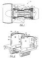
- FIG. 2 is a side view of adjacent turbine airfoils, partially cut-away to show a trailing edge including a plurality of flow dividers.
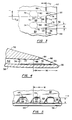
- FIG. 3 is a cross-sectional view of a pair of adjacent flow dividers with a dashed line indicating the location of the flow dividers.
- FIG. 4 is a sectional view taken along line 4-4 of FIG. 2.
- FIG. 5 is an end view taken along line 5-5 of FIG. 2.
- Fig. 1 is an illustration of a gas turbine engine 12 shown as a representation of a typical turbomachine.
- the gas turbine engine includes a compressor 14, a combustor 16, and a turbine 18.
- An axially directed flowpath 22 extends through the gas turbine engine and defines a passage for working fluid.
- Working fluid entering the compressor engages a plurality of compressor airfoils 24 including vanes 26 and rotating blades 28.
- the compressor blades engage the working fluid to add energy to the working fluid.
- Working fluid exiting the compressor enters the combustor where it is mixed with a supply of fuel and the mixture is ignited within the combustor.
- the products of combustion are then expanded within the turbine.
- the turbine includes a plurality of turbine airfoils 32 including turbine vanes 34 and turbine blades 36.
- the turbine blades engage the working fluid to extract energy from the working fluid.
- the turbine vanes orient the working fluid for optimal engagement between working fluid and the axially adjacent, downstream turbine blades.
- a turbine airfoil 32 in the form of a turbine blade 36 is shown in Fig. 2.
- the turbine blade includes an airfoil portion 38, a platform 42, and a root portion 44.
- the airfoil portion extends through the flowpath and engages the working fluid flowing through the flowpath.
- the platform extends laterally about the turbine blade to form a radially inner flow surface 46.
- the flow surface discourages the working fluid from flowing radially inward and not engaging the airfoil portion of the blade.
- the root portion is engaged with a rotor disk 48 to radially secure the turbine blade.
- Cooling passages 52 extend through the turbine blade and are in fluid communication with a supply of cooling fluid. The cooling passages pass through the airfoil portion to transfer heat from the airfoil surfaces to the cooling fluid and to maintain the temperature of the turbine blade below a maximum allowable temperature.
- the turbine blade includes a leading edge 54, a pressure surface 56, a suction surface 58, and a cutback trailing edge 62.
- the cutback trailing edge defines means for ejecting cooling fluid from the airfoil portion of the blade.
- the cooling passages are disposed between the pressure surface wall and the suction surface wall.
- the cutback trailing edge is defined by a pressure surface lip 64 and a suction surface lip 66 which extends downstream of a pressure surface lip.
- the cutback trailing edge includes a plurality of radially spaced flow dividers 68 which extend laterally between the pressure surface wall and the suction surface wall.
- Cooling channels 72 are disposed between adjacent flow dividers and provide fluid communication between the internal cooling passages of the turbine blade and the flowpath.
- Each of the flow dividers is teardrop shaped in cross-section as shown in Fig. 3.
- Each of the flow dividers include a rounded leading edge 74, a constant thickness section 76, and an axially converging section 78.
- the rounded leading edge faces inward towards the cooling flow passages within the turbine blade.
- the rounded leading edge is a semi-circle in cross-section, although it should be apparent to those skilled in the art that other non-circular blunt shapes may be equally applicable to the leading edge of the flow dividers.
- the constant thickness section includes a pair of parallel sidewalls 82 which are radially spaced from each other. Each of the parallel sidewalls is also radially spaced from and parallel to a parallel sidewall of an adjacent flow divider.
- the parallel sidewalls of adjacent flow dividers in conjunction with the pressure wall and suction wall, define constant area channels 84 of constant width between the flow dividers.
- the converging section of the flow dividers includes a pair of converging sidewalls 86, each of which extends from the downstream end 88 of a parallel side and nearly converges at their downstream end 92 with the opposing angled side. As shown in FIG. 3, the converging sidewalls do not completely converge in a point but have approach each other.
- the angled sides of adjacent flow dividers in conjunction with the pressure wall and suction wall, define a covered diffusing region 94 between adjacent flow dividers. This diffusing region begins upstream of the pressure surface lip and extends downstream between the pressure surface wall and the suction surface wall.
- An uncovered diffusing region 96 defined by the angled sides and suction wall, extends downstream of the pressure surface lip and over the suction surface lip.
- Cooling fluid is flowed through the passages within the airfoil portion to provide cooling of the turbine airfoil. A portion of this cooling fluid is ejected out through the cutback trailing edge and into the flowpath. The cooling fluid exiting the cutback trailing edge flows through the channels defined by the radially disposed flow dividers. Heat is transferred directly from the pressure wall and suction wall to the cooling fluid and indirectly via the flow dividers. The exiting cooling fluid first impinges upon the flow divider leading edge to provide impingement type cooling of the flow divider and to indirectly transfer heat from the pressure wall and suction wall.
- the cooling fluid then passes through the constant area channel in which additional heat is transferred between the cooling flow flowing through the constant area channel and the flow dividers, suction wall, and pressure wall.
- the cooling fluid flowing through the constant area channel becomes more fully developed and organized as it passes through the constant area channel before exiting into the diffusing region.
- the cooling fluid exiting the constant area channel then enters the covered diffusing region where the diffusing of the cooling fluid begins.
- the covered diffusing region permits the cooling fluid to begin diffusing before engaging with the working fluid flowing externally to the airfoil portion and over the suction surface lip.
- the cooling fluid Upon exiting the covered diffusing region the cooling fluid continues diffusing over the suction surface lip and provides a film of cooling fluid over the suction surface lip.
- This film of cooling fluid provides a buffer between the hot working fluid and the suction surface lip and cools the suction surface wall.
- Beginning the diffusion upstream of the pressure surface lip provides means to initiate a controlled diffusion before the diffusing cooling fluid exits the airfoil portion and is engaged by the hot working fluid flowing over the airfoil portion. Controlled diffusion upstream of the pressure lip results in an orderly and efficient diffusing film of cooling fluid over the suction surface lip.
- the flow divider leading edge as shown in Fig. 3 is a semi-circle having a diameter D le wherein D le as shown in Fig. 3 also corresponds to the thickness of the constant thickness section of the flow divider. It is suggested that D le should be within the following range: 1D H ⁇ D le ⁇ 3D H Factors to be considered in determining D le are the flow requirements through the trailing edge and the amount of heat transfer desired. If D le is too large, there may not be sufficient flow area to eject the cooling fluid. This may limit the flow of cooling fluid through the turbine airfoil and thereby negatively impact the amount of heat transfer upstream of the trailing edge. In addition, if D Le is too small, cooling impingement cooling of the leading edge will be minimal.
- the constant thickness section includes a width equal to D le as discussed previously and a length L 1 . It is suggested that the length L 1 be equal to or less than three hydraulic diameters D H . It is beneficial to have a constant area channel to form an organized flow of cooling fluid entering the diffusing section. A long constant area channel, however, may increase the risk of overheating if a channel becomes blocked.
- the angled sides of the converging region form an angle ⁇ with a line parallel to the straight sides of the constant thickness section, as shown in Fig. 3. It is suggested that the diffusion angle ⁇ be selected according to the following equation 2° ⁇ ⁇ ⁇ 10° Diffusion angles ⁇ less than 2° may not provide sufficient diffusion and diffusion angles ⁇ greater than 10° may result in flow separation from the angled sides depending upon other flow characteristics through the channels.
- the covered diffusion region is defined by the diffusion angle ⁇ discussed previously and a length L 2 defining the distance between the downstream end of the constant thickness section and the pressure surface lip. It is suggested that the length L 2 be equal to or less than 5 hydraulic diameters D H . It should be noted, however, that the length L 2 may be limited by practical considerations, such as the body thickness of the airfoil section in the cutback region.
- the uncovered diffusing region has a length L 3 which corresponds to the length of the cutback or the axial distance between the pressure surface lip and the suction surface lip. It is suggested that the length L 3 be less than or equal to 7 hydraulic diameters D H .
- the actual length L 3 may depend on the body shape of the airfoil portion and the suction surface lip temperatures. If the length L 3 is too long, there may not be sufficient film cooling over the downstream end.
- the flow channels themselves have a height dimension H and a width dimension W.
- the height dimension H is dependent upon the body shape of the airfoil section and upon the wall thickness of the pressure surface wall and the suction surface wall.
- the width W is dependent upon the flow area needed to eject cooling fluid from the airfoil portion and upon the cooling needed in the trailing edge region in the airfoil portion. The necessary flow area will be divided among the plurality of flow channels.
- the cooling requirements in the trailing edge region will determine how many flow dividers are needed in the region to transfer heat from the pressure surface wall and suction surface wall to the cooling fluid flowing through the channels.
Landscapes
- Engineering & Computer Science (AREA)
- Mechanical Engineering (AREA)
- General Engineering & Computer Science (AREA)
- Turbine Rotor Nozzle Sealing (AREA)
Description
Claims (6)
- An airfoil (32) for a turbine engine (12), the turbine engine (12) disposed about a longitudinal axis and including a source of cooling fluid and an axially extending flow path (22) for working fluid, the airfoil (32) extending in use through the flow path (22) and including a pressure wall (56) extending axially and radially about one side of the airfoil (32), the pressure wall (56) including a pressure wall lip (64), a suction wall (58) extending axially and radially about the opposite side of the airfoil (32), the suction wall (58) spaced from the pressure wall (56) and including a suction wall lip (66), wherein the suction wall lip (66) is axially downstream of the pressure wall lip (64), and wherein the suction wall lip (66) and pressure wall lip (64) define a trailing edge (62), and an internal passage (52) in use in fluid communication with the source of cooling fluid, the internal passage (52) defining a cooling fluid flowpath with cooling fluid exiting the trailing edge (62), wherein the airfoil (32) is characterized by including:
a plurality of radially spaced flow dividers (68) extending laterally between the pressure wall (56) and the suction wall (58) and streamwise through the cooling fluid flowpath, and wherein each divider (68) includes a flow divider leading edge (74) a pair of converging sidewalls (86), each of the pair of converging sidewalls (86) extending to a point downstream of the pressure wall lip (64) such that a portion of each of the dividers (68) is exposed to the flow path, the pair of converging sidewalls (86) converging in the downstream direction such that adjacent side walls (86) of adjacent dividers (68) diverge to define a covered diffusing region (94) and an uncovered diffusing region (96) between adjacent dividers (68), wherein the covered diffusing region (94) extends from upstream of the pressure wall lip (64) to the pressure wall lip (64), and the uncovered diffusing region (96) extends from the pressure wall lip (64) to downstream of the pressure wall lip (64), and a pair of parallel sidewalls (82) extending downstream from the flow divider leading edge (74) to the converging sidewalls (86), each of the pair of parallel sidewalls (82) being parallel with one of a pair of parallel side walls of an adjacent divider to define a constant area channel (76) between adjacent dividers (68), each of the constant area channels (76) being immediately upstream of one of the covered diffusing regions (94). - The airfoil (32) according to Claim 1, wherein the flow divider leading edge (74) is semi-circular in cross-section shape such that cooling fluid exiting the airfoil (32) impinges upon the flow divider leading edge (74), and wherein the flow divider leading edge (74) has a diameter DLe, wherein the constant area channel (76) between adjacent flow dividers (68) has a hydraulic diameter DH, and wherein DH ≤ DLe ≤ 3DH.
- The airfoil according to Claim 1 or 2, wherein the converging sidewalls form an angle α with the direction of flow between flow dividers, and wherein 2° ≤ α ≤ 10°.
- The airfoil (32) according to Claim 1, 2 or 3, wherein the constant area channel (76) has a hydraulic diameter DH and a length L1 and wherein L1 ≤ 3DH.
- The airfoil (32) according to Claim 1, 2, 3 or 4, wherein the covered diffusing region (94) extends a distance L2 upstream of the pressure surface lip (64), wherein the constant area channel (76) between adjacent flow dividers (68) has a hydraulic diameter DH, and wherein L2 ≤ 5DH.
- The airfoil (32) according to Claim 1, 2, 3, 4 or 5, wherein the uncovered diffusing region (96) extends a distance L3 downstream of the pressure surface lip (64), wherein the constant area channel (76) between adjacent flow dividers (68) has a hydraulic diameter DH, and wherein L3 ≤ 7DH.
Applications Claiming Priority (3)
| Application Number | Priority Date | Filing Date | Title |
|---|---|---|---|
| US980817 | 1992-11-24 | ||
| US07/980,817 US5368441A (en) | 1992-11-24 | 1992-11-24 | Turbine airfoil including diffusing trailing edge pedestals |
| PCT/US1993/011254 WO1994012771A1 (en) | 1992-11-24 | 1993-11-19 | Turbine airfoil with diffusing pedestals in its trailing edge |
Publications (2)
| Publication Number | Publication Date |
|---|---|
| EP0774047A1 EP0774047A1 (en) | 1997-05-21 |
| EP0774047B1 true EP0774047B1 (en) | 1998-10-14 |
Family
ID=25527862
Family Applications (1)
| Application Number | Title | Priority Date | Filing Date |
|---|---|---|---|
| EP94902312A Expired - Lifetime EP0774047B1 (en) | 1992-11-24 | 1993-11-19 | Turbine airfoil with diffusing pedestals in its trailing edge |
Country Status (5)
| Country | Link |
|---|---|
| US (1) | US5368441A (en) |
| EP (1) | EP0774047B1 (en) |
| JP (1) | JP3340744B2 (en) |
| DE (2) | DE774047T1 (en) |
| WO (1) | WO1994012771A1 (en) |
Families Citing this family (55)
| Publication number | Priority date | Publication date | Assignee | Title |
|---|---|---|---|---|
| US5503529A (en) * | 1994-12-08 | 1996-04-02 | General Electric Company | Turbine blade having angled ejection slot |
| US6103993A (en) * | 1996-07-10 | 2000-08-15 | Mtu Motoren-Und Turbinen-Union Munchen Gmbh | Hollow rotor blade of columnar structure having a single crystal column in which a series of holes are laser drilled |
| US6004100A (en) * | 1997-11-13 | 1999-12-21 | United Technologies Corporation | Trailing edge cooling apparatus for a gas turbine airfoil |
| US6176678B1 (en) * | 1998-11-06 | 2001-01-23 | General Electric Company | Apparatus and methods for turbine blade cooling |
| US6126397A (en) * | 1998-12-22 | 2000-10-03 | United Technologies Corporation | Trailing edge cooling apparatus for a gas turbine airfoil |
| US6241466B1 (en) | 1999-06-01 | 2001-06-05 | General Electric Company | Turbine airfoil breakout cooling |
| US6179565B1 (en) * | 1999-08-09 | 2001-01-30 | United Technologies Corporation | Coolable airfoil structure |
| US6234754B1 (en) | 1999-08-09 | 2001-05-22 | United Technologies Corporation | Coolable airfoil structure |
| US6402470B1 (en) * | 1999-10-05 | 2002-06-11 | United Technologies Corporation | Method and apparatus for cooling a wall within a gas turbine engine |
| DE19963349A1 (en) * | 1999-12-27 | 2001-06-28 | Abb Alstom Power Ch Ag | Blade for gas turbines with throttle cross section at the rear edge |
| EP1167690A1 (en) * | 2000-06-21 | 2002-01-02 | Siemens Aktiengesellschaft | Cooling of the trailing edge of a gas turbine airfoil |
| IT1319140B1 (en) * | 2000-11-28 | 2003-09-23 | Nuovo Pignone Spa | REFRIGERATION SYSTEM FOR STATIC GAS TURBINE NOZZLES |
| EP1213442B1 (en) | 2000-12-05 | 2009-03-11 | United Technologies Corporation | Rotor blade |
| US6616406B2 (en) * | 2001-06-11 | 2003-09-09 | Alstom (Switzerland) Ltd | Airfoil trailing edge cooling construction |
| US6612811B2 (en) * | 2001-12-12 | 2003-09-02 | General Electric Company | Airfoil for a turbine nozzle of a gas turbine engine and method of making same |
| US6551063B1 (en) | 2001-12-20 | 2003-04-22 | General Electric Company | Foil formed structure for turbine airfoil trailing edge |
| US6837687B2 (en) | 2001-12-20 | 2005-01-04 | General Electric Company | Foil formed structure for turbine airfoil |
| US6640546B2 (en) | 2001-12-20 | 2003-11-04 | General Electric Company | Foil formed cooling area enhancement |
| EP1488077B1 (en) * | 2002-03-25 | 2006-07-12 | ALSTOM Technology Ltd | Cooled turbine blade |
| US6969230B2 (en) * | 2002-12-17 | 2005-11-29 | General Electric Company | Venturi outlet turbine airfoil |
| US7008186B2 (en) * | 2003-09-17 | 2006-03-07 | General Electric Company | Teardrop film cooled blade |
| US7255534B2 (en) * | 2004-07-02 | 2007-08-14 | Siemens Power Generation, Inc. | Gas turbine vane with integral cooling system |
| US7246999B2 (en) * | 2004-10-06 | 2007-07-24 | General Electric Company | Stepped outlet turbine airfoil |
| US7503749B2 (en) * | 2005-04-01 | 2009-03-17 | General Electric Company | Turbine nozzle with trailing edge convection and film cooling |
| US7371048B2 (en) * | 2005-05-27 | 2008-05-13 | United Technologies Corporation | Turbine blade trailing edge construction |
| JP4931507B2 (en) * | 2005-07-26 | 2012-05-16 | スネクマ | Cooling flow path formed in the wall |
| US7806659B1 (en) | 2007-07-10 | 2010-10-05 | Florida Turbine Technologies, Inc. | Turbine blade with trailing edge bleed slot arrangement |
| FR2924155B1 (en) * | 2007-11-26 | 2014-02-14 | Snecma | TURBINE DAWN |
| US8096770B2 (en) * | 2008-09-25 | 2012-01-17 | Siemens Energy, Inc. | Trailing edge cooling for turbine blade airfoil |
| US8096771B2 (en) * | 2008-09-25 | 2012-01-17 | Siemens Energy, Inc. | Trailing edge cooling slot configuration for a turbine airfoil |
| US9422816B2 (en) * | 2009-06-26 | 2016-08-23 | United Technologies Corporation | Airfoil with hybrid drilled and cutback trailing edge |
| US20110268583A1 (en) * | 2010-04-30 | 2011-11-03 | General Electric Company | Airfoil trailing edge and method of manufacturing the same |
| US8807945B2 (en) | 2011-06-22 | 2014-08-19 | United Technologies Corporation | Cooling system for turbine airfoil including ice-cream-cone-shaped pedestals |
| US8714927B1 (en) | 2011-07-12 | 2014-05-06 | United Technologies Corporation | Microcircuit skin core cut back to reduce microcircuit trailing edge stresses |
| EP2626167B2 (en) * | 2012-02-10 | 2023-11-22 | Ansaldo Energia IP UK Limited | Method for reconditioning a blade of a gas turbine and also a reconditioned blade |
| US9328617B2 (en) * | 2012-03-20 | 2016-05-03 | United Technologies Corporation | Trailing edge or tip flag antiflow separation |
| US9366144B2 (en) | 2012-03-20 | 2016-06-14 | United Technologies Corporation | Trailing edge cooling |
| US9175569B2 (en) * | 2012-03-30 | 2015-11-03 | General Electric Company | Turbine airfoil trailing edge cooling slots |
| US9017026B2 (en) | 2012-04-03 | 2015-04-28 | General Electric Company | Turbine airfoil trailing edge cooling slots |
| US20130302176A1 (en) * | 2012-05-08 | 2013-11-14 | Robert Frederick Bergholz, JR. | Turbine airfoil trailing edge cooling slot |
| US20130302177A1 (en) * | 2012-05-08 | 2013-11-14 | Robert Frederick Bergholz, JR. | Turbine airfoil trailing edge bifurcated cooling holes |
| US20130302179A1 (en) * | 2012-05-09 | 2013-11-14 | Robert Frederick Bergholz, JR. | Turbine airfoil trailing edge cooling hole plug and slot |
| US9145773B2 (en) | 2012-05-09 | 2015-09-29 | General Electric Company | Asymmetrically shaped trailing edge cooling holes |
| US9482101B2 (en) | 2012-11-28 | 2016-11-01 | United Technologies Corporation | Trailing edge and tip cooling |
| US20140208771A1 (en) * | 2012-12-28 | 2014-07-31 | United Technologies Corporation | Gas turbine engine component cooling arrangement |
| EP3099901B1 (en) * | 2014-01-30 | 2019-10-09 | United Technologies Corporation | Turbine blade with airfoil having a trailing edge cooling pedestal configuration |
| US10563518B2 (en) * | 2016-02-15 | 2020-02-18 | General Electric Company | Gas turbine engine trailing edge ejection holes |
| GB2559177A (en) * | 2017-01-30 | 2018-08-01 | Rolls Royce Plc | A component for a gas turbine engine |
| KR101901682B1 (en) * | 2017-06-20 | 2018-09-27 | 두산중공업 주식회사 | J Type Cantilevered Vane And Gas Turbine Having The Same |
| US10619489B2 (en) * | 2017-09-06 | 2020-04-14 | United Technologies Corporation | Airfoil having end wall contoured pedestals |
| KR101997985B1 (en) * | 2017-10-27 | 2019-07-08 | 두산중공업 주식회사 | Modified J Type Cantilevered Vane And Gas Turbine Having The Same |
| US20200024967A1 (en) * | 2018-07-20 | 2020-01-23 | United Technologies Corporation | Airfoil having angled trailing edge slots |
| US11168570B1 (en) * | 2020-08-27 | 2021-11-09 | Raytheon Technologies Corporation | Cooling arrangement for gas turbine engine components |
| US11352902B2 (en) * | 2020-08-27 | 2022-06-07 | Aytheon Technologies Corporation | Cooling arrangement including alternating pedestals for gas turbine engine components |
| US11454125B1 (en) | 2021-07-19 | 2022-09-27 | Doosan Heavy Industries & Construction Co., Ltd. | Airfoil with directional diffusion region |
Family Cites Families (10)
| Publication number | Priority date | Publication date | Assignee | Title |
|---|---|---|---|---|
| GB1560683A (en) * | 1972-11-28 | 1980-02-06 | Rolls Royce | Turbine blade |
| US4303374A (en) * | 1978-12-15 | 1981-12-01 | General Electric Company | Film cooled airfoil body |
| US4565490A (en) * | 1981-06-17 | 1986-01-21 | Rice Ivan G | Integrated gas/steam nozzle |
| GB2159585B (en) * | 1984-05-24 | 1989-02-08 | Gen Electric | Turbine blade |
| US4601638A (en) * | 1984-12-21 | 1986-07-22 | United Technologies Corporation | Airfoil trailing edge cooling arrangement |
| US4650949A (en) * | 1985-12-23 | 1987-03-17 | United Technologies Corporation | Electrode for electrical discharge machining film cooling passages in an airfoil |
| US4653983A (en) * | 1985-12-23 | 1987-03-31 | United Technologies Corporation | Cross-flow film cooling passages |
| US5102299A (en) * | 1986-11-10 | 1992-04-07 | The United States Of America As Represented By The Secretary Of The Air Force | Airfoil trailing edge cooling configuration |
| JPH03141801A (en) * | 1990-09-19 | 1991-06-17 | Hitachi Ltd | Cooling blade of gas turbine |
| US5243759A (en) * | 1991-10-07 | 1993-09-14 | United Technologies Corporation | Method of casting to control the cooling air flow rate of the airfoil trailing edge |
-
1992
- 1992-11-24 US US07/980,817 patent/US5368441A/en not_active Expired - Lifetime
-
1993
- 1993-11-19 DE DE0774047T patent/DE774047T1/en active Pending
- 1993-11-19 EP EP94902312A patent/EP0774047B1/en not_active Expired - Lifetime
- 1993-11-19 DE DE69321621T patent/DE69321621T2/en not_active Expired - Lifetime
- 1993-11-19 WO PCT/US1993/011254 patent/WO1994012771A1/en active IP Right Grant
- 1993-11-19 JP JP51326794A patent/JP3340744B2/en not_active Expired - Fee Related
Also Published As
| Publication number | Publication date |
|---|---|
| JP3340744B2 (en) | 2002-11-05 |
| DE69321621T2 (en) | 1999-05-27 |
| DE69321621D1 (en) | 1998-11-19 |
| WO1994012771A1 (en) | 1994-06-09 |
| DE774047T1 (en) | 1997-09-04 |
| US5368441A (en) | 1994-11-29 |
| EP0774047A1 (en) | 1997-05-21 |
| JPH08503534A (en) | 1996-04-16 |
Similar Documents
| Publication | Publication Date | Title |
|---|---|---|
| EP0774047B1 (en) | Turbine airfoil with diffusing pedestals in its trailing edge | |
| US6234754B1 (en) | Coolable airfoil structure | |
| US6179565B1 (en) | Coolable airfoil structure | |
| US8083485B2 (en) | Angled tripped airfoil peanut cavity | |
| US5288207A (en) | Internally cooled turbine airfoil | |
| US5688104A (en) | Airfoil having expanded wall portions to accommodate film cooling holes | |
| EP0648918B1 (en) | Film cooling passages for thin walls | |
| US5458461A (en) | Film cooled slotted wall | |
| US11414999B2 (en) | Cooling hole with shaped meter | |
| US6241468B1 (en) | Coolant passages for gas turbine components | |
| US9988933B2 (en) | Cooling hole with curved metering section | |
| US5651662A (en) | Film cooled wall | |
| US5356265A (en) | Chordally bifurcated turbine blade | |
| US5382135A (en) | Rotor blade with cooled integral platform | |
| US8657576B2 (en) | Rotor blade | |
| EP0753100B1 (en) | Turbine shroud segment with serpentine cooling channels | |
| EP0670953B1 (en) | Coolable airfoil structure | |
| US8591190B2 (en) | Blade cooling | |
| EP2110515B1 (en) | Cooling arrangement between two blade platforms for a gas turbine engine | |
| US6129515A (en) | Turbine airfoil suction aided film cooling means | |
| EP2557270A2 (en) | Airfoil including trench with contoured surface | |
| EP2738350B1 (en) | Turbine blade airfoils including showerhead film cooling systems, and methods for forming an improved showerhead film cooled airfoil of a turbine blade | |
| JP2002364305A (en) | Blade or vane to be cooled for turbine engine | |
| GB2395232A (en) | Turbine component | |
| EP3199762B1 (en) | Gas turbine engine component |
Legal Events
| Date | Code | Title | Description |
|---|---|---|---|
| PUAI | Public reference made under article 153(3) epc to a published international application that has entered the european phase |
Free format text: ORIGINAL CODE: 0009012 |
|
| 17P | Request for examination filed |
Effective date: 19950607 |
|
| AK | Designated contracting states |
Kind code of ref document: A1 Designated state(s): DE FR GB |
|
| DET | De: translation of patent claims | ||
| GRAG | Despatch of communication of intention to grant |
Free format text: ORIGINAL CODE: EPIDOS AGRA |
|
| 17Q | First examination report despatched |
Effective date: 19971201 |
|
| GRAG | Despatch of communication of intention to grant |
Free format text: ORIGINAL CODE: EPIDOS AGRA |
|
| GRAH | Despatch of communication of intention to grant a patent |
Free format text: ORIGINAL CODE: EPIDOS IGRA |
|
| GRAH | Despatch of communication of intention to grant a patent |
Free format text: ORIGINAL CODE: EPIDOS IGRA |
|
| GRAA | (expected) grant |
Free format text: ORIGINAL CODE: 0009210 |
|
| AK | Designated contracting states |
Kind code of ref document: B1 Designated state(s): DE FR GB |
|
| REF | Corresponds to: |
Ref document number: 69321621 Country of ref document: DE Date of ref document: 19981119 |
|
| ET | Fr: translation filed | ||
| PLBE | No opposition filed within time limit |
Free format text: ORIGINAL CODE: 0009261 |
|
| STAA | Information on the status of an ep patent application or granted ep patent |
Free format text: STATUS: NO OPPOSITION FILED WITHIN TIME LIMIT |
|
| 26N | No opposition filed | ||
| REG | Reference to a national code |
Ref country code: GB Ref legal event code: IF02 |
|
| PGFP | Annual fee paid to national office [announced via postgrant information from national office to epo] |
Ref country code: FR Payment date: 20021127 Year of fee payment: 10 |
|
| PG25 | Lapsed in a contracting state [announced via postgrant information from national office to epo] |
Ref country code: FR Free format text: LAPSE BECAUSE OF NON-PAYMENT OF DUE FEES Effective date: 20030731 |
|
| REG | Reference to a national code |
Ref country code: FR Ref legal event code: ST |
|
| PGFP | Annual fee paid to national office [announced via postgrant information from national office to epo] |
Ref country code: DE Payment date: 20121114 Year of fee payment: 20 |
|
| PGFP | Annual fee paid to national office [announced via postgrant information from national office to epo] |
Ref country code: GB Payment date: 20121114 Year of fee payment: 20 |
|
| REG | Reference to a national code |
Ref country code: DE Ref legal event code: R071 Ref document number: 69321621 Country of ref document: DE |
|
| REG | Reference to a national code |
Ref country code: DE Ref legal event code: R071 Ref document number: 69321621 Country of ref document: DE |
|
| REG | Reference to a national code |
Ref country code: GB Ref legal event code: PE20 Expiry date: 20131118 |
|
| PG25 | Lapsed in a contracting state [announced via postgrant information from national office to epo] |
Ref country code: DE Free format text: LAPSE BECAUSE OF EXPIRATION OF PROTECTION Effective date: 20131120 Ref country code: GB Free format text: LAPSE BECAUSE OF EXPIRATION OF PROTECTION Effective date: 20131118 |