EP0773677A2 - Method for locally combining optical and acoustic signals - Google Patents
Method for locally combining optical and acoustic signals Download PDFInfo
- Publication number
- EP0773677A2 EP0773677A2 EP96107247A EP96107247A EP0773677A2 EP 0773677 A2 EP0773677 A2 EP 0773677A2 EP 96107247 A EP96107247 A EP 96107247A EP 96107247 A EP96107247 A EP 96107247A EP 0773677 A2 EP0773677 A2 EP 0773677A2
- Authority
- EP
- European Patent Office
- Prior art keywords
- transparent
- display device
- electroacoustic transducers
- image display
- transducers
- Prior art date
- Legal status (The legal status is an assumption and is not a legal conclusion. Google has not performed a legal analysis and makes no representation as to the accuracy of the status listed.)
- Granted
Links
Images


Classifications
-
- H—ELECTRICITY
- H04—ELECTRIC COMMUNICATION TECHNIQUE
- H04N—PICTORIAL COMMUNICATION, e.g. TELEVISION
- H04N5/00—Details of television systems
- H04N5/64—Constructional details of receivers, e.g. cabinets or dust covers
- H04N5/642—Disposition of sound reproducers
Definitions
- the invention relates to a method for local linking of optical and acoustic signals in an audio-visual device with an image and sound reproduction device according to claim 1 and an arrangement of several electroacoustic transducers according to claim 2, which for local linking of optical and acoustic signals in the Above-mentioned audiovisual device can be used.
- claim 9 describes an electrostatic converter for use in the arrangement according to claim 2 and a device with at least one electrostatic converter integrated in a display for local video-sound linking according to claim 13.
- DE-OS 3832616 discloses an electroacoustic transducer with a piezopolymeric, transparent film which is applied to the screen of a television receiver itself. In this way, a match is achieved in the spatial position of the screen and the transducer.
- the known arrangement is not able to create a local link between several optical events on the screen and the associated audio signals, as is the case e.g. is desirable for video conferences with several conference participants.
- the invention is therefore based on the object of providing a method and an arrangement comprising a plurality of electroacoustic transducers which enable improved local linking of optical and acoustic signals in an audiovisual device with an image and sound reproduction device. It is a further object of the invention to improve an electrostatic transducer in such a way that it can be used in the transducer arrangement according to the invention. Another object of the invention is to provide a device for the local linking of optical and acoustic signals, which comprises a display and at least one electrostatic converter integrated therein.
- the local linkage of image and sound signals in an audio-visual device is achieved in particular by the fact that several electroacoustic transducers in Arranged in the immediate vicinity of the image display device and electrically controlled independently of one another in such a way that the optical events taking place in different image areas of the image display device can be superimposed with the sound signals belonging to them, which are emitted by the corresponding electroacoustic transducers.
- a perceptual coincidence of image and sound signals can be achieved for all image locations, since the electroacoustic transducers each emit the sound signals from the point on the screen at which the associated visual information is also generated.
- optical and acoustic signals are obtained if several transparent transducers, which can be controlled electrically independently of one another, are arranged in the form of a matrix in front of the image display device.
- Piezoelectric and / or electrostatic converters are used as transparent converters.
- a direct local picture-sound link can advantageously be realized in that the electrostatic converters are integrated into the surface of the picture display device itself.
- the surface of the image display device is designed to be electrically conductive and serves as a counterelectrode for the transducer, which also has a transparent, electrically conductive membrane for emitting the sound energy.
- An important area of application in which the invention can gain great importance is in the video conferencing sector. For some time now, efforts have been made to develop ever larger displays with which the conference participants can be shown in natural size. Here the great advantage of the invention is shown in the fact that a viewing conference participant Always perceives voice signal on the screen location of his display, at which the currently speaking conference participant is shown. Thanks to the transducer arrangement according to the invention, speech intelligibility can be improved in a video conference and the communication quality can be increased in general.
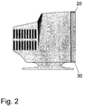
- FIG. 1 shows an audio-visual device 10, such as a television receiver, which is divided into six image areas or windows 15. It is assumed that a so-called multipoint video conference is taking place between seven conference participants and that a television receiver according to FIG. 1 is set up for each conference participant. It should be pointed out that the invention can also be used in conventional video conferences in which two groups of people are located at two locations. Each conference participant sees the six other conference participants in one of the windows 15 on the screen of their television receiver 10 so that the viewing conference participant can not only see who is speaking to whom, but also the speaking participant acoustically can correctly localize, a matrix 30 of six transparent electrostatic electroacoustic transducers 20 can be arranged in front of the screen of the television receiver 10, as can also be seen in FIG. 2.
- Each window 15 is thus directly associated with its own converter 20.
- the six transducer elements 20 can expediently be controlled electrically independently of one another, so that the speech signals of the speaking conference participant are only emitted by the transducer 20 which is located directly in front of the window 15 in which the speaking participant is currently being displayed. If the image signals of the six separate image areas 15 are to be coupled with the associated acoustic signals in the correct location, the television receiver 10 or the converter matrix 30 must be able to apply the six transmitted audio channels to the correct converter 20.
- a low-frequency loudspeaker 17 can be provided below the screen of the television receiver 10, which radiates the low-frequency components of the sound signal to be reproduced from all (for example 6) channels.
- FIG. 3 shows an embodiment of an electrostatic converter 20 as it can be used in the converter matrix 30.
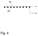
- the electrostatic converter 20 has a transparent counter electrode 40 and a thin, transparent and electrically conductive membrane 50.
- the membrane 50 can be, for example, a plastic film which can be vapor-coated with metal on one side or can be made electrically conductive by another method.
- the membrane 50 and the counter electrode 40 are converted to the sound energy Signal voltage and a polarization voltage applied.
- the polarization voltage is a DC voltage and serves to linearize the transmission characteristic of the converter 20, as a result of which signal distortions are avoided.
- An electrically conductive glass, metal-vapor-coated plastic films or highly transparent metal grids (networks) can be used as the counter electrode 40. With the help of such a transparent metal grating shown in FIG. 4, the efficiency of the electrostatic converter 20 can be increased and its frequency response can be linearized. This effect results from the fact that between the membrane 50 and the grid-shaped counterelectrode 40 there are many small cavities and thus many small sound transducers. The small sound transducers created in this way, which have dimensions of approximately 0.5 to 5 mm, are always able to vibrate in the basic mode.
- a similar effect is achieved if a transparent, wavy structured and electrically conductive surface, which acts as a counter electrode for the converter 20, is applied to the screen surface of the television receiver 10.
- the membrane 50 is then applied to the roughened surface, for example provided with nubs.
- many small converters are created, which contribute to improving the efficiency of converter 20.
- the transparent electrostatic converter 20 shown in FIGS. 3 and 4 can be one of the six converter elements of the matrix 30.
- the screen surface of a television receiver itself is used as a counter electrode, for example by making it electrically conductive by means of metal vapor deposition.
- An electrically conductive plastic film then only has to be placed as a membrane at a suitable distance in front of the picture tube.
- the one to preload with the The DC voltage required for the screen surface of the integrated converter can be obtained, for example, from the high-voltage source, which is usually available in monitors with a conventional Braun tube.
- An electroacoustic transducer can also be integrated into the production of modern LC, TFT or other displays in order to achieve an efficient and direct local connection of optical and acoustic signals.
- An electrostatic converter integrated in a display is shown in FIG. 5.
- the converter has an outer display layer 60 on which a conductive transparent layer is applied as a counter electrode 70.
- an insulating, transparent intermediate layer 80 is applied between them, which must have a predetermined degree of elasticity.
- the intermediate layer 80 is then able to carry out small thickness vibrations in the order of magnitude of approximately 0.1 mm, so that the electrically conductive and transparent membrane 90 located above it can move.
- transparent piezoelectric transducers can also be used in the matrix 30 arranged in front of the screen of the television receiver.
- a simpler possibility for local picture-sound coupling, which does not require transparent electroacoustic transducers, is to arrange a plurality of electroacoustic transducers laterally, above and / or below the television receiver 10. With six transducers correspondingly arranged around the screen, a sufficient coincidence of optical and acoustic signals can be generated, for example, in the video conference shown in FIG. 1. It should be noted that all transducers can be controlled electrically independently of one another. As electro-acoustic Converters can be used with ordinary electrodynamic converters. To improve the local linking of optical and acoustic signals, transparent radiator elements can additionally be provided directly from the image area of the television receiver, each of which is acoustically connected to a transducer located outside the screen.
- the sound energy generated by the transducers is transmitted to the radiating element either by airborne sound or by structure-borne sound.
- a channel is required which is designed in such a way that it can transmit the desired audio frequency range.
- Flat cavities with outlet openings or elements with transparent foils are used to emit the transmitted sound energy.
- Rigid waveguides between each transducer and each radiator element are necessary for structure-borne sound transmission.
- the transformation of structure-borne noise into airborne sound, ie the radiation of the sound energy, takes place by means of rigid transparent surfaces, such as foils or glass.
- Another way to correctly link the optical and acoustic signals in an audio-visual system is to arrange non-transparent, electroacoustic transducers behind a screen.
- This transducer arrangement is, however, only for so-called frontal projections, such as. B. at the cinema or video, possible. Thanks to the invention, it is possible to achieve a perceptual coincidence of image and sound signals for all screen locations.
- a corresponding number of electroacoustic transducers are used for this purpose, each of which emits its sound signal from the position on the screen that actually provides the associated visual information. The best local coupling of optical and acoustic information is obtained if a transparent converter system is located directly in front of the screen is arranged.
- the picture-sound system is also multi-channel capable, ie each converter only emits the sound signals that belong to the screen window that is directly assigned to the converter.
- Such a sound reproduction technique is particularly useful for quasi-static image information, as is the case, for example, in video conferences.
Landscapes
- Engineering & Computer Science (AREA)
- Multimedia (AREA)
- Signal Processing (AREA)
- Details Of Audible-Bandwidth Transducers (AREA)
- Optical Communication System (AREA)
- Stereophonic System (AREA)
- Two-Way Televisions, Distribution Of Moving Picture Or The Like (AREA)
- Devices For Indicating Variable Information By Combining Individual Elements (AREA)
Abstract
Description
Die Erfindung betrifft ein Verfahren zur lokalen Verknüpfung von optischen und akustischen Signalen bei einem audio-visuellen Gerät mit einer Bild- und Tonwiedergabeeinrichtung gemäß Anspruch 1 und eine Anordnung aus mehreren elektroakustischen Wandlern gemäß Anspruch 2, die zur lokalen Verknüpfung von optischen und akustischen Signalen bei dem obgengenannten audiovisuellen Gerät einsetzbar ist.
Darüber hinaus ist in Anspruch 9 ein elektrostatischer Wandler zur Verwendung in der Anordnung nach Anspruch 2 sowie eine Vorrichtung mit wenigstens einem in einem Display integrierten elektrostatischen Wandler zur lokalen Bild-Ton-Verknüpfung gemäß Anspruch 13 umschrieben.The invention relates to a method for local linking of optical and acoustic signals in an audio-visual device with an image and sound reproduction device according to claim 1 and an arrangement of several electroacoustic transducers according to claim 2, which for local linking of optical and acoustic signals in the Above-mentioned audiovisual device can be used.
In addition, claim 9 describes an electrostatic converter for use in the arrangement according to claim 2 and a device with at least one electrostatic converter integrated in a display for local video-sound linking according to claim 13.
Die Sprach- und Tonwiedergabe bei audio-visuellen Geräten, wie z.B. bei Fernsehgeräten und Monitoren, geschieht z.Z. über herkömmliche dynamische Lautsprecher, die außerhalb der Bildschirmebene, meistens seitlich oder unterhalb des Bildschirmgerätes angeordnet sind. Bei derart angeordneten Lautsprechern findet zwischen den auf dem Bildschirm dargestellten optischen Informationen und den von den Lautsprechern abgestrahlten Schallsignalen keine oder nur eine geringe lokale Kopplung statt. Zwar wurden in der Vergangenheit Mehrkanal-Tonwiedergabetechniken, wie z.B. das "Dolby-Surround-Verfahren", entwickelt, die den Zuschauer aus mehreren Richtungen in der Horizontalebene beschallen können. Doch fehlt auch bei dieser Technik eine unmittelbare lokale Zuordnung von Audiosignalen zu den dazugehörigen Bildsignalen. Mit anderen Worten kann ein Zuschauer die zusammengehörenden Bild- und Tonsignale nicht an der gleichen Stelle des Bildschirms wahrnehmen.The speech and sound reproduction in audio-visual devices, such as television sets and monitors, currently takes place via conventional dynamic loudspeakers, which are arranged outside the screen level, usually to the side or below the screen device. In loudspeakers arranged in this way, there is little or no local coupling between the optical information displayed on the screen and the sound signals emitted by the loudspeakers. In the past, multi-channel sound reproduction techniques, such as the "Dolby Surround method", have been developed which can sound the viewer from several directions in the horizontal plane. However, this technology also lacks a direct local association of audio signals with the associated image signals. In other words, a viewer cannot perceive the related picture and sound signals in the same place on the screen.
Statt die Lautsprecher außerhalb der Bildschirmebene anzuordenen, offenbart die DE-OS 3832616 einen elektroakustischen Wandler mit einer piezopolymeren, transparenten Folie, die auf dem Bildschirm eines Fernsehempfängers selbst aufgebracht ist. Auf diese Weise wird zwar eine Übereinstimmung in der räumlichen Lage des Bildschirms und des Wandlers erreicht. Allerdings ist die bekannte Anordnung nicht in der Lage, eine lokale Verknüpfung zwischen mehreren optischen Ereignissen auf dem Bildschirm und den dazugehörigen Tonsignalen zu erzeugen, wie dies z.B. bei Videokonferenzen mit mehreren Konferenzteilnehmern wünschenswert ist.Instead of arranging the loudspeakers outside the screen level, DE-OS 3832616 discloses an electroacoustic transducer with a piezopolymeric, transparent film which is applied to the screen of a television receiver itself. In this way, a match is achieved in the spatial position of the screen and the transducer. However, the known arrangement is not able to create a local link between several optical events on the screen and the associated audio signals, as is the case e.g. is desirable for video conferences with several conference participants.
Der Erfindung liegt daher die Aufgabe zugrunde, ein Verfahren und eine Anordnung aus mehreren elektroakustischen Wandlern zur Verfügung zu stellen, die eine verbesserte lokale Verknüpfung von optischen und akustischen Signalen bei einem audiovisuellen Gerät mit einer Bild- und Tonwiedergabeeinrichtung ermöglichen. Es ist ein weiteres Ziel der Erfindung, einen elektrostatischen Schallwandler derart zu verbessern, daß er in der erfindungsgemäßen Wandler-Anordnung einsetzbar ist. Ein weiteres Ziel der Erfindung ist darin zu sehen, eine Vorrichtung zur lokalen Verknüpfung von optischen und akustischen Signalen zu schaffen, die ein Display und wenigstens einen darin integrierten elektrostatischen Wandler umfaßt.The invention is therefore based on the object of providing a method and an arrangement comprising a plurality of electroacoustic transducers which enable improved local linking of optical and acoustic signals in an audiovisual device with an image and sound reproduction device. It is a further object of the invention to improve an electrostatic transducer in such a way that it can be used in the transducer arrangement according to the invention. Another object of the invention is to provide a device for the local linking of optical and acoustic signals, which comprises a display and at least one electrostatic converter integrated therein.
Die Erfindung löst die technologisch zusammenhängenden Probleme jeweils durch die Merkmale der Ansprüche 1, 2, 9 und 13.The invention solves the technologically related problems by the features of claims 1, 2, 9 and 13, respectively.
Weitere vorteilhafte Ausgestaltungen sind in den Unteransprüchen definiert.Further advantageous refinements are defined in the subclaims.
Die lokale Verknüpfung von Bild- und Tonsignalen bei einem audio-visuellen Gerät erreicht die Erfindung insbesondere dadurch, daß mehrere elektroakustische Wandler in unmittelbarer Nähe der Bildwiedergabeeinrichtung derart angeordnet und unabhängig voneinander elektrisch angesteuert werden, daß sich die an unterschiedlichen Bildbereichen der Bildwiedergabeeinrichtung stattfindenden optischen Ereignisse mit den zu ihnen gehörenden Schallsignalen, die von den entsprechenden elektroakustischen Wandlern abgestrahlt werden, ortsrichtig überlagern können. Auf diese Weise kann eine Wahrnehmungskoinzidenz von Bild- und Tonsignalen für alle Bildorte erreicht werden, da die elektroakustischen Wandler die Schallsignale jeweils von der Stelle des Bildschirms abstrahlen, an der auch die zugehörige visuelle Information entsteht.The local linkage of image and sound signals in an audio-visual device is achieved in particular by the fact that several electroacoustic transducers in Arranged in the immediate vicinity of the image display device and electrically controlled independently of one another in such a way that the optical events taking place in different image areas of the image display device can be superimposed with the sound signals belonging to them, which are emitted by the corresponding electroacoustic transducers. In this way, a perceptual coincidence of image and sound signals can be achieved for all image locations, since the electroacoustic transducers each emit the sound signals from the point on the screen at which the associated visual information is also generated.
Eine optimale lokale Verknüpfung von optischen und akustischen Signalen ergibt sich dann, wenn mehrere transparente, unabhängig voneinander elektrisch ansteuerbare Wandler in Form einer Matrix vor der Bildwiedergabeeinrichtung angeordnet sind. Als transparente Wandler kommen beispielsweise piezoelektrische und/oder elektrostatische Wandler zum Einsatz.An optimal local combination of optical and acoustic signals is obtained if several transparent transducers, which can be controlled electrically independently of one another, are arranged in the form of a matrix in front of the image display device. Piezoelectric and / or electrostatic converters, for example, are used as transparent converters.
Eine unmittelbare lokale Bild-Ton-Verknüpfung läßt sich vorteilhafterweise dadurch realisieren, daß die elektrostatischen Wandler in die Oberfläche der Bildwiedergabeeinrichtung selbst intergiert sind. In diesem Fall ist die Oberfläche der Bildwiedergabeeinrichtung elektrisch leitfähig ausgebildet und dient für den Wandler als Gegenelektrode, der zudem eine transparente, elektrisch leitfähige Membran zum Abstrahlen der Schallenergie aufweist.
Ein wichtiges Anwendungsgebiet, auf dem die Erfindung große Bedeutung erlangen kann, ist der Videokonferenzsektor. Es werden seit geraumer Zeit Anstrengungen unternommen, immer größere Displays zu entwickeln, mit denen die Konferenzteilnehmer in natürlicher Größe dargestellt werden können. Hier zeigt sich der große Vorteil der Erfindung darin, daß ein betrachtender Konferenzteilnehmer das Sprachsignal immer an dem Bildschirmort seines Displays wahrnimmt, an dem der gerade sprechende Konfernzteilnehmer dargestellt wird. Dank der erfindungsgemäßen Wandleranordnung kann die Sprachverständlichkeit bei einer Videokonferenz verbessert und die Kommunikationsqualität ganz allgemein gesteigert werden.A direct local picture-sound link can advantageously be realized in that the electrostatic converters are integrated into the surface of the picture display device itself. In this case, the surface of the image display device is designed to be electrically conductive and serves as a counterelectrode for the transducer, which also has a transparent, electrically conductive membrane for emitting the sound energy.
An important area of application in which the invention can gain great importance is in the video conferencing sector. For some time now, efforts have been made to develop ever larger displays with which the conference participants can be shown in natural size. Here the great advantage of the invention is shown in the fact that a viewing conference participant Always perceives voice signal on the screen location of his display, at which the currently speaking conference participant is shown. Thanks to the transducer arrangement according to the invention, speech intelligibility can be improved in a video conference and the communication quality can be increased in general.
Die Erfindung wird nachfolgend anhand der Ausführungsbeispiele in Verbindung mit den beiliegenden Zeichnungen näher erläutert. Es zeigen:
- Fig. 1
- eine mögliche Anordnung transparenter Wandler vor einem Bildschirm eines Fernsehempfängers,
- Fig. 2
- die Seitenansicht des Fernsehempfängers nach Fig. 1,
- Fig. 3
- den prinzipiellen Aufbau eines elektrostatischen Wandlers, der in der erfindungsgemäßen Anordnung einsetzbar ist,
- Fig. 4
- eine vereinfachte prinzipielle Darstellung eines elektrostatischen Wandlers, der aus vielen kleinen Schallstrahlern besteht, und
- Fig. 5
- den Querschnitt eines in einem Display integrierten elektrostatischen Wandlers.
- Fig. 1
- a possible arrangement of transparent converters in front of a screen of a television receiver,
- Fig. 2
- the side view of the television receiver of FIG. 1,
- Fig. 3
- the basic structure of an electrostatic converter that can be used in the arrangement according to the invention,
- Fig. 4
- a simplified schematic representation of an electrostatic converter that consists of many small sound emitters, and
- Fig. 5
- the cross section of an electrostatic converter integrated in a display.
In Fig. 1 ist ein audio-visuelles Gerät 10, wie z.B. ein Fernsehempfänger, dargestellt, der in sechs Bildbereiche oder Fenster 15 unterteilt ist. Es sei angenommen, daß gerade eine sogenannte Multipoint-Videokonferenz, zwischen sieben Konferenzteilnehmern stattfindet und bei jedem Konferenzteilnehmer ein Fernsehempfänger nach Fig. 1 aufgestellt ist. Es sei darauf hingewiesen, daß die Erfindung auch bei herkömmlichen Videokonferenzen anwendbar ist, bei denen sich zwei Peronengruppen an zwei Orten aufhalten. Jeder Konferenzteilnehmer sieht auf dem Bildschirm seines Fernsehempfänger 10 die sechs anderen Konferenzteilnehmer in jeweils einem der Fenster 15. Damit der betrachtende Konferenzteilnehmer nicht nur sehen kann, wer mit wem spricht, sondern auch den sprechenden Teilnehmer akustisch richtig lokalisieren kann, kann eine Matrix 30 aus sechs transparenten elektrostatischen Elektroakustik-Wandlern 20 vor dem Bildschirm des Fernsehempfängers 10 angeordnet sein, wie dies auch in Fig. 2 zu sehen ist. Jedem Fenster 15 ist somit unmittelbar ein eigener Wandler 20 zugeordnet.
Zweckmäßigerweise können die sechs Wandlerelemente 20 unabhängig voneinander elektrisch angesteuert werden, so daß die Sprachsignale des sprechenden Konferenzteilnehmers nur von dem Wandler 20 abgestrahlt werden, der sich unmittelbar vor dem Fenster 15 befindet, in dem der sprechende Teilnehmer gerade dargestellt wird. Sollen die Bildsignale der sechs getrennten Bildbereiche 15 mit den dazugehörigen akustischen Signalen ortsrichtig gekoppelt werden, muß der Fernsehempfänger 10 bzw. die Wandler-Matrix 30 in der Lage sein, die sechs übertragenen Tonkanäle jeweils an den richtigen Wandler 20 anzulegen. Unterhalb des Bildschirms des Ferneshempfängers 10 kann ein Tieftonlautsprecher 17 vorgesehen sein, der die tieffrequenten Anteile des wiederzugebenden Schallsignals aller (z.B. 6) Kanäle abstrahlt. Dies erscheint sinnvoll, da die Richtungslokalisierung des menschlichen Gehörs bei tiefen Frequenzen nur schwach ausgeprägt ist, und die Wandler vor dem Bildschirm (nach dem elektrostatischen oder piezoelektrischen Prinzip) bei tiefen Frequenzen nur geringe Schalleistungen abstrahlen können. Man überträgt deshalb lediglich die höheren Frequenzen über den transparenten Wandler 20.
In Fig. 3 ist eine Ausführungsform eines elektrostatischen Wandlers 20 dargestellt, wie er in der Wandlermatrix 30 verwendet werden kann. Der elektrostatische Wandler 20 weist eine transparente Gegenelektrode 40 und eine dünne, transparente und elektrisch leitfähige Membran 50 auf. Bei der Membran 50 kann es sich beispielsweise um eine Kunsstoffolie handeln, die einseitig mit Metall bedampft oder nach einem anderen Verfahren elektrisch leitfähig gemacht werden kann. An die Membran 50 und die Gegenelektrode 40 wird die in Schallenergie umzuwandelnde Signalspannung und eine Polarisationsspannung angelegt. Die Polarisationsspannung ist eine Gleichspannung und dient der Linearisierung der Übertragungskennlinie des Wandlers 20, wodurch Signalverzerrungen vermieden werden. Als Gegenelektrode 40 können ein elektrisch leitfähiges Glas, metallbedampfte Kunststoffolien oder hochtransparente Metallgitter (Netze) verwendet werden. Mit Hilfe eines solchen in Fig. 4 dargestellten transparenten Metallgitters kann der Wirkungsgrad des elektrostatischen Wandlers 20 erhöht und sein Frequenzgang linearisiert werden. Diese Wirkung ergibt sich daraus, daß zwischen der Membran 50 und der gitterförmigen Gegenelektrode 40 viele kleine Hohlräume und somit viele kleine Schallwandler entstehen. Die so entstandenen kleinen Schallwandler, die Abmessungen von etwa 0,5 bis 5 mm aufweisen, sind in der Lage, stets in der Grundmode zu schwingen. Einen ähnlichen Effekt erzielt man, wenn eine transparente, wellig strukturierte und elektrisch leitfähige Oberfläche, die als Gegenelektrode für den Wandler 20 wirkt, auf die Bildschirmoberfläche des Fernsehempfängers 10 aufgebracht ist. Auf die aufgeraute, beispielsweise mit Noppen versehene Oberfläche wird anschließend die Membran 50 aufgebracht. Auch hier entstehen wiederum viele kleine Wandler, die zur Verbesserung des Wirkungsgrades des Wandlers 20 beitragen. Wie bereits erwähnt, kann der in Fig. 3 und 4 dargestellte transparente elektrostatische Wandler 20 eines der sechs Wandlerelemente der Matrix 30 sein.
Neben der oben geschilderten separaten Anordnung von transparenten Wandlern vor dem Bildschirme zur Bild-Ton-Verknüpfung ist es durchaus denkbar, transparente Wandler gleich in den Bildschirm zu integrieren.
Hierzu wird die Bildschirmoberfläche eines Fernsehempfängers selbst als Gegenelektrode benutzen, indem sie z.B. mittels Metallbedampfung elektrisch leitfähig gemacht wird. Eine elektrisch leitfähige Kunststoffolie muß dann lediglich noch als Membran in einem geeigneten Abstand vor der Bildröhre platziert werden. Die zum Vorspannen eines mit der Bildschirmoberfläche integrierten Wandlers benötigte Gleichspannung läßt sich beispielsweise aus der Hochspannungsquelle gewinnen, die üblicherweise in Monitoren mit einer herkömmlichen Braun'schen Röhre zur Verfügung steht.1 shows an audio-
The six
FIG. 3 shows an embodiment of an
In addition to the above-described separate arrangement of transparent converters in front of the screens for video-sound linkage, it is quite conceivable to integrate transparent converters directly into the screen.
For this purpose, the screen surface of a television receiver itself is used as a counter electrode, for example by making it electrically conductive by means of metal vapor deposition. An electrically conductive plastic film then only has to be placed as a membrane at a suitable distance in front of the picture tube. The one to preload with the The DC voltage required for the screen surface of the integrated converter can be obtained, for example, from the high-voltage source, which is usually available in monitors with a conventional Braun tube.
Auch bei der Herstellung von modernen LC-, TFT- oder anderen Displays kann ein elektroakustischer Wandler gleich mitintegriert werden, um eine effiziente und direkte lokale Verknüpfung von optischen und akustischen Signalen zu erreichen. Ein in einem Display integrierter elektrostatischer Wandler ist in Fig. 5 dargestellt. Der Wandler weist eine äußere Displayschicht 60 auf, auf der eine leitfähige transparente Schicht als Gegenelektrode 70 aufgebracht ist. Um einen geeigneten Abstand zwischen der Gegenelektrode 70 und einer Membran 90 sicherzustellen, wird dazwischen eine isolierende, transparente Zwischenschicht 80 aufgebracht, die einen vorbestimmten Elastizitätsgrad besitzen muß. Die Zwischenschicht 80 ist dann in der Lage, kleine Dickenschwingungen in der Größenordnung von etwa 0,1 mm auszuführen, so daß sich die darüber befindliche, elektrisch leitfähige und transparente Membran 90 bewegen kann. Neben transparenten elektrostatischen Wandlern 20 können auch transparente piezoelektrische Wandler in der vor dem Bildschirm des Fernsehempfängers angeordneten Matrix 30 benutzt werden.An electroacoustic transducer can also be integrated into the production of modern LC, TFT or other displays in order to achieve an efficient and direct local connection of optical and acoustic signals. An electrostatic converter integrated in a display is shown in FIG. 5. The converter has an outer display layer 60 on which a conductive transparent layer is applied as a
Eine einfachere Möglichkeit zur lokalen Bild-Ton-Kopplung, die keine transparenten elektroakustischen Wandler erfordert, besteht darin, mehrere elektroakustische Wandler seitlich, oberhalb und/oder unterhalb des Fernsehempfängers 10 anzuordnen. Mit sechs entsprechend um den Bildschirm angeordneten Wandlern läßt sich z.B. bei der in Fig. 1 dargestellten Videokonferenz noch eine ausreichende Koinzidenz von optischen und akustischen Signalen erzeugen. Es sei angemerkt, daß alle Wandler elektrisch unabhängig voneinander angesteuert werden können. Als elektroakustische Wandler können gewöhnliche elektrodynamische Wandler zum Einsatz kommen. Zur Verbesserung der lokalen Verknüpfung von optischen und akustischen Signalen können zusätzlich transparente Strahlerelemente unmittelbar von der Bildfläche des Fernsehempfängers vorgesehen sein, die jeweils mit einem außerhalb des Bildschirms sitzenden Wandler akustisch verbunden sind. Die von den Wandlern erzeugte Schallenergie wird entweder durch Luftschall oder durch Körperschall zum abstrahlenden Element übertragen. Bei der Luftschallübertragung ist ein Kanal erforderlich, der derart ausgestaltet ist, daß er den gewünschten Tonfrequenzbereich übertragen kann. Zur Abstrahlung der übertragenen Schallenergie kommen u.a. flache Hohlräume mit Austrittsöffnungen oder Elemente mit transparenten Folien zum Einsatz. Für eine Körperschallübertragung sind steife Wellenleiter zwischen jedem Wandler und jedem Strahlerelement notwendig. Die Umwandlung des Körperschalls in Luftschall, d.h. die Abstrahlung der Schallenergie, erfolgt dabei mittels steifer transparenter Flächen, wie z.B. Folien oder Glas.A simpler possibility for local picture-sound coupling, which does not require transparent electroacoustic transducers, is to arrange a plurality of electroacoustic transducers laterally, above and / or below the
Eine weitere Möglichkeit, die optischen und akustischen Signale in einem audio-visuellen System örtlich richtig zu verknüpfen, besteht darin, nicht-transparente, elektroakustische Wandler hinter einer Leinwand anzuordnen. Diese Wandleranordung ist allerdings nur bei sogenannten Frontalprojektionen, wie z. B. bei der Kino- oder Videoprofektion, möglich.
Dank der Erfindung ist es möglich, eine Wahrnehmungskoinzidenz von Bild- und Tonsignalen für alle Bildschirmorte zu erzielen. Dazu werden entsprechend viele elektroakustische Wandler verwendet, die ihr Schallsignal jeweils von der Stelle des Bildschirms abstrahlen, die auch tatsächlich die zugehörige visuelle Information liefert. Die beste lokale Kopplung von optischer und akustischer Information ergibt sich dann, wenn ein transparentes Wandlersystem unmittelbar vor der Bildschirmfläche angeordnet ist. Das Bild-Ton-System ist außerdem mehrkanalfähig, d. h. jeder Wandler strahlt nur die Tonsignale ab, die zu dem Bildschirmfenster gehören, das dem Wandler unmittelbar zugeordnet ist. Bei quasi statischen Bildinformationen, wie dies z.B. bei Videokonferenzen der Fall ist, ist eine solche Tonwiedergabe-Technik besonders nützlich.Another way to correctly link the optical and acoustic signals in an audio-visual system is to arrange non-transparent, electroacoustic transducers behind a screen. This transducer arrangement is, however, only for so-called frontal projections, such as. B. at the cinema or video, possible.
Thanks to the invention, it is possible to achieve a perceptual coincidence of image and sound signals for all screen locations. A corresponding number of electroacoustic transducers are used for this purpose, each of which emits its sound signal from the position on the screen that actually provides the associated visual information. The best local coupling of optical and acoustic information is obtained if a transparent converter system is located directly in front of the screen is arranged. The picture-sound system is also multi-channel capable, ie each converter only emits the sound signals that belong to the screen window that is directly assigned to the converter. Such a sound reproduction technique is particularly useful for quasi-static image information, as is the case, for example, in video conferences.
Claims (13)
dadurch gekennzeichnet,
daß mehrere elektroakustische Wandler (20) in unmittelbarer Nähe der Bildwiedergabeeinrichtung (10) derart angeordnet und unabhängig voneinander elektrisch angesteuert werden, daß sich die an unterschiedlichen Bildbereichen (15) der Bildwiedergabeeinrichtung (10) stattfindenden optischen Ereignisse mit den zu ihnen gehörenden Schallsignalen, die von den entsprechenden elektroakustischen Wandlern (20) abgestrahlt werden, ortsrichtig überlagern können.Method for locally linking optical (image) and acoustic (sound) signals in an audio-visual device with an image and sound reproduction device,
characterized,
that several electroacoustic transducers (20) are arranged in the immediate vicinity of the image display device (10) and are electrically controlled independently of one another such that the optical events taking place in different image areas (15) of the image display device (10) with the associated sound signals are from the corresponding electroacoustic transducers (20) are emitted, can be superimposed in the correct location.
dadurch gekennzeichnet, daß die elektroakustischen Wandler (20) in unmittelbarer Nähe der Bildwiedergabeeinrichtung derart angeordnet und unabhängig voneinander elektrisch ansteuerbar sind, daß sich die an unterschiedlichen Bildbereichen (15) der Bildwiedergabeeinrichtung stattfindenden optischen Ereignisse mit den zu ihnen gehörenden Schallsignalen, die von den entsprechenden Wandlern (20) abgestrahlt werden, ortsrichtig überlagern können.Arrangement of several electroacoustic transducers which can be used for the local linking of optical and acoustic signals in an audio-visual device with an image display device,
characterized in that the electroacoustic transducers (20) are arranged in the immediate vicinity of the image display device and can be controlled electrically independently of one another such that the optical events taking place in different image areas (15) of the image display device are associated with the sound signals belonging to them, from the corresponding transducers (20) can be emitted, superimposed in the correct location.
einem Display zur Darstellung der optischen Signale und wenigstens einem elektrostatischen Wandler, der aufweist:
a display for displaying the optical signals and at least one electrostatic converter, which has:
Applications Claiming Priority (2)
| Application Number | Priority Date | Filing Date | Title |
|---|---|---|---|
| DE19542147A DE19542147A1 (en) | 1995-11-11 | 1995-11-11 | Process for the local linking of optical and acoustic signals |
| DE19542147 | 1995-11-11 |
Publications (3)
| Publication Number | Publication Date |
|---|---|
| EP0773677A2 true EP0773677A2 (en) | 1997-05-14 |
| EP0773677A3 EP0773677A3 (en) | 2000-03-22 |
| EP0773677B1 EP0773677B1 (en) | 2002-03-13 |
Family
ID=7777256
Family Applications (1)
| Application Number | Title | Priority Date | Filing Date |
|---|---|---|---|
| EP96107247A Expired - Lifetime EP0773677B1 (en) | 1995-11-11 | 1996-05-08 | Method for locally combining optical and acoustic signals |
Country Status (4)
| Country | Link |
|---|---|
| US (1) | US6477256B1 (en) |
| EP (1) | EP0773677B1 (en) |
| AT (1) | ATE214533T1 (en) |
| DE (2) | DE19542147A1 (en) |
Cited By (1)
| Publication number | Priority date | Publication date | Assignee | Title |
|---|---|---|---|---|
| DE102012220801A1 (en) * | 2012-11-14 | 2014-06-12 | Bayerische Motoren Werke Aktiengesellschaft | Method for assigning participants in telephone conference call to speakers of e.g. car, involves receiving audio signals of participants of conference call who are outside of vehicle |
Families Citing this family (7)
| Publication number | Priority date | Publication date | Assignee | Title |
|---|---|---|---|---|
| DE19806509B4 (en) * | 1998-02-17 | 2007-12-13 | Harman Becker Automotive Systems Gmbh | Device for information reproduction |
| DE19859868A1 (en) * | 1998-12-23 | 2000-06-29 | Tony E Kula | Television receiver with built in video and audio transmission and reception facility for video conferencing |
| US6791519B2 (en) * | 2001-04-04 | 2004-09-14 | Koninklijke Philips Electronics N.V. | Sound and vision system |
| DE10338694B4 (en) * | 2003-08-22 | 2005-08-25 | Siemens Ag | Reproduction device comprising at least one screen for displaying information |
| US20110103624A1 (en) * | 2009-11-03 | 2011-05-05 | Bran Ferren | Systems and Methods for Providing Directional Audio in a Video Teleconference Meeting |
| JP2011254967A (en) * | 2010-06-08 | 2011-12-22 | Universal Entertainment Corp | Gaming machine |
| CN108601450A (en) * | 2015-11-25 | 2018-09-28 | 托马斯·米切尔·戴尔 | Surround sound application for vertical orientation content and device |
Citations (6)
| Publication number | Priority date | Publication date | Assignee | Title |
|---|---|---|---|---|
| DE846558C (en) * | 1950-08-03 | 1952-08-14 | Schaub Appbau Ges M B H G | Loudspeaker for television receiver |
| EP0323110A2 (en) * | 1987-12-21 | 1989-07-05 | Matsushita Electric Industrial Co., Ltd. | Projection screen device |
| DE3832616A1 (en) * | 1988-09-26 | 1990-03-29 | Electronic Werke Deutschland | Loudspeaker |
| EP0361249A1 (en) * | 1988-09-26 | 1990-04-04 | E W D Electronic-Werke Deutschland Gmbh | Sound reproduction set for screens |
| JPH04237288A (en) * | 1991-01-21 | 1992-08-25 | Nippon Telegr & Teleph Corp <Ntt> | Audio signal output method for plural-picture window display |
| DE4420212A1 (en) * | 1994-06-04 | 1995-12-07 | Deutsche Bundespost Telekom | Transmission system for simultaneous multiple sending of several picture and sound signals |
Family Cites Families (8)
| Publication number | Priority date | Publication date | Assignee | Title |
|---|---|---|---|---|
| US4352039A (en) * | 1980-07-25 | 1982-09-28 | The United States Of America As Represented By The Secretary Of The Army | Sonic transducer |
| JPH0231288A (en) * | 1988-07-21 | 1990-02-01 | Matsushita Electric Ind Co Ltd | Card device |
| US4965819A (en) * | 1988-09-22 | 1990-10-23 | Docu-Vision, Inc. | Video conferencing system for courtroom and other applications |
| DE3832617A1 (en) * | 1988-09-26 | 1990-03-29 | Electronic Werke Deutschland | Loudspeaker for a digital control signal |
| US5115472A (en) * | 1988-10-07 | 1992-05-19 | Park Kyung T | Electroacoustic novelties |
| GB8924334D0 (en) * | 1989-10-28 | 1989-12-13 | Hewlett Packard Co | Audio system for a computer display |
| DE4115221C2 (en) * | 1991-05-10 | 1994-09-01 | Sennheiser Electronic | Electroacoustic transducer based on the electrostatic principle |
| WO1995026102A1 (en) * | 1994-03-24 | 1995-09-28 | Philips Electronics N.V. | Audio-visual arrangement and system in which such an arrangement is used |
-
1995
- 1995-11-11 DE DE19542147A patent/DE19542147A1/en not_active Withdrawn
-
1996
- 1996-05-08 AT AT96107247T patent/ATE214533T1/en not_active IP Right Cessation
- 1996-05-08 DE DE59608873T patent/DE59608873D1/en not_active Expired - Fee Related
- 1996-05-08 EP EP96107247A patent/EP0773677B1/en not_active Expired - Lifetime
- 1996-11-08 US US08/744,912 patent/US6477256B1/en not_active Expired - Fee Related
Patent Citations (6)
| Publication number | Priority date | Publication date | Assignee | Title |
|---|---|---|---|---|
| DE846558C (en) * | 1950-08-03 | 1952-08-14 | Schaub Appbau Ges M B H G | Loudspeaker for television receiver |
| EP0323110A2 (en) * | 1987-12-21 | 1989-07-05 | Matsushita Electric Industrial Co., Ltd. | Projection screen device |
| DE3832616A1 (en) * | 1988-09-26 | 1990-03-29 | Electronic Werke Deutschland | Loudspeaker |
| EP0361249A1 (en) * | 1988-09-26 | 1990-04-04 | E W D Electronic-Werke Deutschland Gmbh | Sound reproduction set for screens |
| JPH04237288A (en) * | 1991-01-21 | 1992-08-25 | Nippon Telegr & Teleph Corp <Ntt> | Audio signal output method for plural-picture window display |
| DE4420212A1 (en) * | 1994-06-04 | 1995-12-07 | Deutsche Bundespost Telekom | Transmission system for simultaneous multiple sending of several picture and sound signals |
Non-Patent Citations (1)
| Title |
|---|
| PATENT ABSTRACTS OF JAPAN vol. 017, no. 003 (E-1301), 6. Januar 1993 (1993-01-06) & JP 04 237288 A (NIPPON TELEGR & TELEPH CORP), 25. August 1992 (1992-08-25) * |
Cited By (1)
| Publication number | Priority date | Publication date | Assignee | Title |
|---|---|---|---|---|
| DE102012220801A1 (en) * | 2012-11-14 | 2014-06-12 | Bayerische Motoren Werke Aktiengesellschaft | Method for assigning participants in telephone conference call to speakers of e.g. car, involves receiving audio signals of participants of conference call who are outside of vehicle |
Also Published As
| Publication number | Publication date |
|---|---|
| DE19542147A1 (en) | 1997-05-15 |
| EP0773677A3 (en) | 2000-03-22 |
| US6477256B1 (en) | 2002-11-05 |
| ATE214533T1 (en) | 2002-03-15 |
| DE59608873D1 (en) | 2002-04-18 |
| EP0773677B1 (en) | 2002-03-13 |
Similar Documents
| Publication | Publication Date | Title |
|---|---|---|
| DE69213748T2 (en) | SOUND RECORDING SYSTEM AND SOUND RECORDING AND PLAYING DEVICE | |
| DE69803168T2 (en) | VIDEO CONFERENCE SYSTEM | |
| DE2639834C2 (en) | Multi-channel sound recording and playback system | |
| DE102014217344A1 (en) | SPEAKER SYSTEM | |
| DE2910117A1 (en) | ARRANGEMENT FOR REPLAYING TWO-CHANNEL TRANSMITTED SOUND EVENTS | |
| DE2244162B2 (en) | Method for simulating the auditory events that occur during loudspeaker exposure using headphones | |
| EP1484944A2 (en) | Method for reproducing an audio signal with an ultrasonic loudspeaker | |
| DE69232863T2 (en) | Speaker arrangement for a television set | |
| DE2803411A1 (en) | HEADPHONES FOR IMPROVED SPATIAL HEARING | |
| EP0773677B1 (en) | Method for locally combining optical and acoustic signals | |
| DE19715365A1 (en) | Condenser microphone | |
| EP1078300B1 (en) | Projection Screen | |
| DE4033068A1 (en) | TELEVISION RECEIVER WITH STEREO SOUND PLAYBACK | |
| DE3733095A1 (en) | STEREO DEVICE WITH A PIEZOELECTRIC MEMBRANE SPEAKER | |
| DE1121116B (en) | Condenser microphone | |
| DE3442388C1 (en) | Method for audio transmission in a high-resolution television system | |
| DE4420212A1 (en) | Transmission system for simultaneous multiple sending of several picture and sound signals | |
| DE3233990C2 (en) | Methods and devices for improved reproduction of phantom sound sources | |
| WO2006048006A1 (en) | System for playing back audio signals | |
| DE2455336C3 (en) | Interference loudspeaker system for stereophonic reproduction | |
| DE102014221583B4 (en) | Electroacoustic transducer and receiver | |
| EP3267621B1 (en) | Method for generating an overall room noise for passing to a real endpoint, use of said method and teleconferencing system | |
| DE2637305A1 (en) | Stereophonic microphone simulating human head - has dynamic inserts with acoustic compensation approaching human ear stereophonic response (OE151076) | |
| DE3302394A1 (en) | Loudspeaker | |
| DE3620170A1 (en) | Circuit arrangement for a sound reproduction device |
Legal Events
| Date | Code | Title | Description |
|---|---|---|---|
| PUAI | Public reference made under article 153(3) epc to a published international application that has entered the european phase |
Free format text: ORIGINAL CODE: 0009012 |
|
| AK | Designated contracting states |
Kind code of ref document: A2 Designated state(s): AT BE CH DE DK ES FR GB IT LI SE |
|
| PUAL | Search report despatched |
Free format text: ORIGINAL CODE: 0009013 |
|
| AK | Designated contracting states |
Kind code of ref document: A3 Designated state(s): AT BE CH DE DK ES FR GB IT LI SE |
|
| 17P | Request for examination filed |
Effective date: 20000922 |
|
| 17Q | First examination report despatched |
Effective date: 20001206 |
|
| GRAG | Despatch of communication of intention to grant |
Free format text: ORIGINAL CODE: EPIDOS AGRA |
|
| GRAG | Despatch of communication of intention to grant |
Free format text: ORIGINAL CODE: EPIDOS AGRA |
|
| GRAH | Despatch of communication of intention to grant a patent |
Free format text: ORIGINAL CODE: EPIDOS IGRA |
|
| REG | Reference to a national code |
Ref country code: GB Ref legal event code: IF02 |
|
| GRAH | Despatch of communication of intention to grant a patent |
Free format text: ORIGINAL CODE: EPIDOS IGRA |
|
| GRAA | (expected) grant |
Free format text: ORIGINAL CODE: 0009210 |
|
| AK | Designated contracting states |
Kind code of ref document: B1 Designated state(s): AT BE CH DE DK ES FR GB IT LI SE |
|
| PG25 | Lapsed in a contracting state [announced via postgrant information from national office to epo] |
Ref country code: IT Free format text: LAPSE BECAUSE OF FAILURE TO SUBMIT A TRANSLATION OF THE DESCRIPTION OR TO PAY THE FEE WITHIN THE PRESCRIBED TIME-LIMIT;WARNING: LAPSES OF ITALIAN PATENTS WITH EFFECTIVE DATE BEFORE 2007 MAY HAVE OCCURRED AT ANY TIME BEFORE 2007. THE CORRECT EFFECTIVE DATE MAY BE DIFFERENT FROM THE ONE RECORDED. Effective date: 20020313 Ref country code: GB Free format text: LAPSE BECAUSE OF FAILURE TO SUBMIT A TRANSLATION OF THE DESCRIPTION OR TO PAY THE FEE WITHIN THE PRESCRIBED TIME-LIMIT Effective date: 20020313 Ref country code: FR Free format text: LAPSE BECAUSE OF FAILURE TO SUBMIT A TRANSLATION OF THE DESCRIPTION OR TO PAY THE FEE WITHIN THE PRESCRIBED TIME-LIMIT Effective date: 20020313 |
|
| REF | Corresponds to: |
Ref document number: 214533 Country of ref document: AT Date of ref document: 20020315 Kind code of ref document: T |
|
| REG | Reference to a national code |
Ref country code: CH Ref legal event code: EP |
|
| REF | Corresponds to: |
Ref document number: 59608873 Country of ref document: DE Date of ref document: 20020418 |
|
| PG25 | Lapsed in a contracting state [announced via postgrant information from national office to epo] |
Ref country code: AT Free format text: LAPSE BECAUSE OF NON-PAYMENT OF DUE FEES Effective date: 20020508 |
|
| PG25 | Lapsed in a contracting state [announced via postgrant information from national office to epo] |
Ref country code: LI Free format text: LAPSE BECAUSE OF NON-PAYMENT OF DUE FEES Effective date: 20020531 Ref country code: CH Free format text: LAPSE BECAUSE OF NON-PAYMENT OF DUE FEES Effective date: 20020531 Ref country code: BE Free format text: LAPSE BECAUSE OF NON-PAYMENT OF DUE FEES Effective date: 20020531 |
|
| PG25 | Lapsed in a contracting state [announced via postgrant information from national office to epo] |
Ref country code: SE Free format text: LAPSE BECAUSE OF FAILURE TO SUBMIT A TRANSLATION OF THE DESCRIPTION OR TO PAY THE FEE WITHIN THE PRESCRIBED TIME-LIMIT Effective date: 20020613 Ref country code: DK Free format text: LAPSE BECAUSE OF FAILURE TO SUBMIT A TRANSLATION OF THE DESCRIPTION OR TO PAY THE FEE WITHIN THE PRESCRIBED TIME-LIMIT Effective date: 20020613 |
|
| GBV | Gb: ep patent (uk) treated as always having been void in accordance with gb section 77(7)/1977 [no translation filed] |
Effective date: 20020313 |
|
| PG25 | Lapsed in a contracting state [announced via postgrant information from national office to epo] |
Ref country code: ES Free format text: LAPSE BECAUSE OF FAILURE TO SUBMIT A TRANSLATION OF THE DESCRIPTION OR TO PAY THE FEE WITHIN THE PRESCRIBED TIME-LIMIT Effective date: 20020925 |
|
| EN | Fr: translation not filed | ||
| REG | Reference to a national code |
Ref country code: CH Ref legal event code: PL |
|
| PLBE | No opposition filed within time limit |
Free format text: ORIGINAL CODE: 0009261 |
|
| STAA | Information on the status of an ep patent application or granted ep patent |
Free format text: STATUS: NO OPPOSITION FILED WITHIN TIME LIMIT |
|
| 26N | No opposition filed |
Effective date: 20021216 |
|
| PGFP | Annual fee paid to national office [announced via postgrant information from national office to epo] |
Ref country code: DE Payment date: 20030318 Year of fee payment: 8 |
|
| PG25 | Lapsed in a contracting state [announced via postgrant information from national office to epo] |
Ref country code: DE Free format text: LAPSE BECAUSE OF NON-PAYMENT OF DUE FEES Effective date: 20041201 |