EP0773110A2 - Set of tape cartridges and printing apparatus - Google Patents
Set of tape cartridges and printing apparatus Download PDFInfo
- Publication number
- EP0773110A2 EP0773110A2 EP96114988A EP96114988A EP0773110A2 EP 0773110 A2 EP0773110 A2 EP 0773110A2 EP 96114988 A EP96114988 A EP 96114988A EP 96114988 A EP96114988 A EP 96114988A EP 0773110 A2 EP0773110 A2 EP 0773110A2
- Authority
- EP
- European Patent Office
- Prior art keywords
- tape
- tape cassette
- cassette
- image
- type
- Prior art date
- Legal status (The legal status is an assumption and is not a legal conclusion. Google has not performed a legal analysis and makes no representation as to the accuracy of the status listed.)
- Granted
Links
Images


Classifications
-
- B—PERFORMING OPERATIONS; TRANSPORTING
- B41—PRINTING; LINING MACHINES; TYPEWRITERS; STAMPS
- B41J—TYPEWRITERS; SELECTIVE PRINTING MECHANISMS, i.e. MECHANISMS PRINTING OTHERWISE THAN FROM A FORME; CORRECTION OF TYPOGRAPHICAL ERRORS
- B41J3/00—Typewriters or selective printing or marking mechanisms characterised by the purpose for which they are constructed
- B41J3/407—Typewriters or selective printing or marking mechanisms characterised by the purpose for which they are constructed for marking on special material
- B41J3/4075—Tape printers; Label printers
Landscapes
- Impression-Transfer Materials And Handling Thereof (AREA)
- Handling Of Continuous Sheets Of Paper (AREA)
Abstract
Description
Die Erfindung bezieht sich auf einen Satz von Bandkassetten und insbesondere eine Bildempfangsbandkassette in Verbindung mit eine Bildübertragungsbandkassette oder eine Thermo-Direktdruckbandkassette, die in einem Thermodruckgerät verwendbar sind.The invention relates to a set of tape cartridges, and more particularly, to an image receiving tape cartridge in connection with an image transfer tape cartridge or a thermal direct printing tape cartridge usable in a thermal printing apparatus.
Druckgeräte allgemeiner Art, mit denen sich die vorliegende Erfindung befaßt, sind bekannt. Sie arbeiten mit einem ein Bild aufzunehmenden Bandvorrat und einem Mittel zur Übertragung des Bildes auf das Band. Bei einem bekannten Gerät enthält ein Bandkassette einen Vorrat an Bildempfangsband sowie einen Vorrat an Bildübertragungsband, wobei das Bildempfangsband und das Bildübertragungsband in gegenseitiger Überdeckung durch eine Druckzone des Druckgeräts geführt werden. In der Druckzone wirkt ein Thermodruckkopf mit einer Gegendruckwalze zusammen, um ein Bild vom Bildübertragungsband auf das Biidempfangsband zu übertragen. Ein mit einer Bandkassette der vorgenannten Art arbeitendes Druckgerät ist zum Beispiel in der EP-A-0267890 (Varitronics, Inc.) beschrieben. Es sind weitere Druckgeräte hergestellt worden, bei denen mittels eines Trockenbeschriftungs- oder Trockenfilmdruckverfahrens Buchstaben auf ein Bildempfangsband übertragen werden. Bei all diesen Druckgeräten ist der Aufbau des Bildempfangsbands im wesentlich gleich. Das heißt, es besteht aus einer oberen, ein Bild aufnehmenden Schicht, die mittels einer adhäsiven Schicht an einer lösbaren Rückseitenschicht befestigt ist.General pressure devices with which the present invention is concerned are known. They work with a supply of tapes to be recorded and a means of transferring the image to the tape. In a known device, a tape cassette contains a supply of image receiving tape and a supply of image transfer tape, the image receiving tape and the image transfer tape being guided in mutual overlap through a printing zone of the printing device. In the printing zone, a thermal print head interacts with a counter-pressure roller in order to transfer an image from the image transfer belt to the image receiving belt. A printing device working with a tape cassette of the aforementioned type is for example in EP-A-0267890 (Varitronics, Inc.). Further printing devices have been manufactured in which letters are transferred to an image receiving tape by means of a dry lettering or dry film printing method. In all of these printing devices, the structure of the image receiving tape is essentially the same. This means that it consists of an upper, image-receiving layer which is attached to a releasable backing layer by means of an adhesive layer.
Sobald ein Bild oder eine Nachricht auf das Band gedruckt worden ist, wird dieser Abschnitt des Bandes abgeschnitten, um ihn als Etikett verwenden zu können. Die lösbare Rückseitenschicht wird von der oberen Schicht entfernt, um die obere Schicht mittels der adhäsiven Schicht an einer Oberfläche anbringen zu können.Once an image or message has been printed on the tape, that portion of the tape is cut off so that it can be used as a label. The releasable backing layer is removed from the top layer in order to be able to attach the top layer to a surface by means of the adhesive layer.
Bei einem anderen Banddruckgerät, wie es in EP-A-0322919 (Brother Kogyo KK) beschrieben ist, enthält eine Bandkassette einen Vorrat eines transparenten Bildempfangsbandes und einen Vorrat eines Bildübertragungsbandes. Das Bandkassette enthält außerdem einen Vorrat an Rückseitenband, das eine Trägerschicht mit einer adhäsiven Schicht auf ihrer Unterseite, an der ein abziehbares Rückseitenpapier angebracht ist, und eine adhäsive Schicht auf seiner Oberseite umfaßt, die am dem Bildempfangsband befestigbar ist, nachdem ein Bild darauf gedruckt wurde. In diesem Gerät wird das Bild als Spiegelbild auf das Bildempfangsband gedruckt, das richtig herum erscheint, wenn man durch das Bildempfangsband blickt. Bei diesem Gerät ist der Aufdruck geschützt, wenn das Etikett benutzt wird.In another tape printing device as described in EP-A-0322919 (Brother Kogyo KK), a tape cassette contains a supply of a transparent image receiving tape and a supply of an image transfer tape. The tape cassette also contains a supply of backing tape which includes a backing having an adhesive layer on its underside to which a peelable backing paper is attached and an adhesive layer on its top which is attachable to the image receiving tape after an image has been printed thereon . In this device, the image is printed as a mirror image on the image receiving tape, which appears the right way round when you look through the image receiving tape. With this device, the print is protected when the label is used.
In all diesen Geräten sind die Farbe des Drucks und des Etiketts durch den Inhalt der Bandkassette vorbestimmt. Die Farbe des Etiketts bezieht sich auf die obere Schicht des Bildempfangsbandes des in EP-A-0267890 beschriebenen Gerätes und die Trägerschicht des in Bezug auf EP-A-0322919 beschriebenen Gerätes. Die Farbe des Drucks wird durch die Farbe des Bildübertragungsbandes festgelegt. Somit können Etiketten einer bestimmten Farbe nur mit Tinte einer bestimmten Farbe bedruckt werden. Weiterhin werden sie gemeinsam enden, da Bildempfangsband und Bildübertragungsband in einer gemeinsamen Bandkassette enthalten sind.In all of these devices, the color of the print and the label are predetermined by the content of the tape cassette. The color of the label relates to the top layer of the image receiving tape of the device described in EP-A-0267890 and the backing layer of the device described in relation to EP-A-0322919. The color of the print is determined by the color of the image transfer belt. This means that labels of a certain color can only be printed with ink of a certain color. Furthermore, they will end together because the image receiving tape and the image transfer tape are contained in a common tape cassette.
In einem anderen Gerät, das in der GB-A-2161754 offenbart ist, sind zwei getrennte Bandkassetten vorhanden, die zusammengeklipst sind, um eine einzige Einheit zu formen, die dann in eine Maschine einsetzbar ist, wobei die Bandkassetten Farbband und Substratband von einer seitlichen Position in Richtung auf eine Druckposition zu bereitstellen. Um eine Bandkassette durch eine andere zu ersetzen, ist es notwendig, die Bandkassette zu entklipsen, die gewünschte Bandkassette zu ersetzen und die Bandkassetten zusammenzuklipsen, bevor sie in das Gerät eingesetzt werden. Dies macht das System schwierig zu benutzen.In another device disclosed in GB-A-2161754 there are two separate ribbon cartridges which are clipped together to form a single unit which is then insertable into a machine, the ribbon cartridges ribbon and substrate ribbon from a side To provide position towards a printing position. To replace one tape cartridge with another, it is necessary to unclip the tape cartridge, replace the desired tape cartridge, and clip the tape cartridges together before inserting them into the device. This makes the system difficult to use.
In einem anderen Gerät sind zwei Bandkassetten vorhanden, eine Tintenfarbbandkassette ist nestartig innerhalb einer Substratbandkassette auf einer gemeinsamen Seite der Druckzone angeordnet. Dies bedeutet, daß es knifflig und schwierig ist, die Tintenfarbbandkassette zum Wechseln zu entnehmen. Außerdem sind die äußeren Abmessungen der Tintenfarbbandkassette durch die Abmessungen des Substratbandes festgelegt, so daß ihre Größe oder Kapazität nur auf Kosten des Substratbandes vergrößert werden könnte.Another device has two ribbon cartridges, an ink ribbon cartridge is nest-like within a substrate ribbon cartridge on a common side of the print zone. This means that it is tricky and difficult to remove the ink ribbon cartridge for replacement. Furthermore the outer dimensions of the ink ribbon cassette are determined by the dimensions of the substrate ribbon, so that their size or capacity could only be increased at the expense of the substrate ribbon.
Ein Druckgerät, das die obigen Probleme löst, ist aus der EP-A-0573187 bekannt. Dieses Dokument offenbart ein Druckgerät, das erste und zweite Bandkassettenaufnahmebereiche hat, die an gegenüberliegenden Seiten einer Druckzone angeordnet sind. Der erste Bandkassettenaufnahmebereich dient zur Aufnahme einer Bandkassette, die einen Vorrat an Bildübertragungsband enthält. Der zweite Bandkassettenaufnahmebereich dient zur Aufnahme einer Bandkassette, die einen Vorrat an Bildempfangsband enthält. Auf diese Weise können die ersten und zweiten Bandkassetten individuell entfernbar und austauschbar sein.A printing device which solves the above problems is known from EP-A-0573187. This document discloses a printing device having first and second tape cassette receiving areas located on opposite sides of a printing zone. The first tape cassette receiving area is used to receive a tape cassette that contains a supply of image transfer tape. The second tape cassette receiving area is used to receive a tape cassette that contains a supply of image receiving tape. In this way, the first and second tape cassettes can be removed and replaced individually.
Dieses Druckgerät hat einen großen Anwendungsbereich. Es hat jedoch die Einschränkung, daß die gegenwärtig erhältlichen Breiten des Bildempfangsbandes eine maximale Breite von 19 mm haben. Derzeit sind Breiten des Bildempfangsbandes von 6 mm, 12 mm und 19 mm erhältlich. Diese arbeiten alle mit Bildübertragungsband mit einer Breite von 19 mm zusammen. Es ist jedoch wünschenswert, Bildempfangsband größerer Breiten von beispielsweise 24 mm und 32 mm bereitzustellen. Offensichtlich ist Bildübertragungsband einer Breite von 19 mm nicht breit genug für die volle Ausdehnung eines Bildempfangsbandes einer Breite von 24 mm oder 32 mm. Es ist daher wünschenswert, eine Bandkassette mit Bildübertragungsband bereitzustellen, das eine größere Breite aufweist. Dies stellt jedoch ein Problem für das in EP-A-0573187 beschriebene Gerät dar, da ein Benutzer unbeabsichtigt versuchen könnte, eine Bandkassette mit einem Bildempfangsband geringer Breite mit einer Bandkassette mit einem Bildübertragungsband großer Breite zu benutzen (oder umgekehrt), wenn beide Breiten des Bildübertragungsbandes verfügbar wären. Im ersten Fall würde sich das Bildübertragungsband über das Bildempfangsband hinaus ausdehnen und könnte somit Tinte auf die Druckwalze übertragen. Im zweiten Fall wäre das Bildübertragungsband nicht breit genug, Tinte über die ganze Ausdehnung des Bildempfangsbandes zu übertragen.This pressure device has a wide range of applications. However, it has the limitation that the currently available widths of the image receiving tape have a maximum width of 19 mm. 6 mm, 12 mm and 19 mm widths of the image reception band are currently available. These all work together with an image transfer belt with a width of 19 mm. However, it is desirable to provide image receiving tape of larger widths, for example 24 mm and 32 mm. Obviously, the 19 mm wide image transfer belt is not wide enough to fully expand the 24 mm or 32 mm wide image receiving belt. It is therefore desirable to provide a tape cassette with an image transfer tape which has a larger width. However, this poses a problem for the device described in EP-A-0573187 because of a user could unintentionally try to use a tape cassette with a narrow width image receiving tape with a tape cassette with a wide width image transfer belt (or vice versa) if both widths of the image transfer belt were available. In the first case, the image transfer belt would expand beyond the image receive belt and thus could transfer ink to the platen. In the second case, the image transfer belt would not be wide enough to transfer ink across the entire length of the image receive belt.
Nach einem ersten Aspekt der Erfindung ist ein Satz von Bandkassetten vorgeschlagen, umfassend wenigstens zwei Bandkassetten eines ersten Typs und zwei Bandkassetten eines zweiten Typs, wobei Bandkassetten des ersten Typs Bildempfangsband mit jeweils unterschiedlichen Bandparametern enthalten und Bandkassetten des zweiten Typs Bildübertragungsband mit jeweils unterschiedlichen Bandparametern enthalten, und wobei jede Bandkassette des ersten Typs ein erstes Zusammenwirkungsmittel aufweist, abhängig vom Bandparameter des Bildempfangsbandes, und jede Bandkassette des zweiten Typs ein zweites Zusammenwirkungsmittel aufweist, abhängig vom Bandparameter des Bildübertragungsbandes, wobei die ersten und zweiten Zusammenwirkungsmittel derart angeordnet sind, daß sie selektiv miteinander zusammenwirken und nur ein Zusammenwirken einer ordnungsgemäß ausgewählten Bandkassette des zweiten Typs mit den Bandkassetten des ersten Typs erlauben und anderenfalls ein Zusammenwirken der Bandkassetten ausschließen.According to a first aspect of the invention, a set of tape cassettes is proposed, comprising at least two tape cassettes of a first type and two tape cassettes of a second type, tape cassettes of the first type containing image receiving tape with different tape parameters in each case and tape cartridges of the second type containing image transfer tape with different tape parameters in each case, and wherein each of the first type of tape cassettes has a first cooperation means depending on the tape parameter of the image receiving tape, and each of the second type tape cassettes has a second cooperation means depending on the tape parameter of the image transfer belt, the first and second cooperation means being arranged to selectively cooperate with each other and only allow a properly selected tape cassette of the second type to cooperate with the tape cassettes of the first type, and otherwise to cooperate the tape cassette exclude.
In der beschriebenen Ausführungsform ist der Bandparameter die Breite des Bandes. Es ist auch möglich, die Erfindung mit anderen Bandparametern, wie Farbe oder Art des Bildempfangbandes oder -übertragungsbandes, zu verwenden, um sicherzustellen, daß nur ordnungsgemäß zusammenpassende Bänder zusammenwirken können.In the described embodiment, the band parameter is the width of the band. It is also possible to share the invention with others Use tape parameters such as color or type of image receiving tape or transfer tape to ensure that only properly matching tapes can work together.
Eines der ersten und zweiten Zusammenwirkungsmittel kann eine von der Bandkassette abstehende Komponente umfassen, deren Form vom Parameter des Bandes abhängt.One of the first and second cooperation means can comprise a component projecting from the tape cassette, the shape of which depends on the parameter of the tape.
Das jeweils andere der ersten und zweiten Zusammenwirkungsmittel kann ein in die Bandkassette eingebrachter Einschnitt sein, dessen Form vom Parameter des Bandes abhängt und derart gestaltet ist, daß nur die Komponente der ordnungsgemäß ausgewählten Bandkassette darin aufnehmbar ist.The respective other of the first and second interaction means can be an incision made in the tape cassette, the shape of which depends on the parameter of the tape and is designed such that only the component of the properly selected tape cassette can be accommodated therein.
Diese Anordnung hat nicht nur den Vorteil, daß Bandkassetten 'gemischt und passend verbunden' werden können, sondern, daß sichergestellt ist, daß die jeweilige Art von Bildempfangsband nur mit einer geeigneten Art von Bildübertragungsband verwendet wird. In der bevorzugten Ausführungsform, in der der Bandparameter die Breite ist, wird Bildübertragungsband in zwei Breiten von 19 mm und 28 mm bereitgestellt. Die Breite von 19 mm ist geeignet zur Verwendung mit Bildempfangsband mit einer Breite von 6 mm, 12 mm und 19 mm. Die Breite von 28 mm des Bildübertragungsbandes ist geeignet zur Verwendung von Bildempfangsband mit einer Breite von 24 mm oder 32 mm.This arrangement not only has the advantage that tape cartridges can be 'mixed and matched' but also ensures that the particular type of image receiving tape is used only with a suitable type of image transfer tape. In the preferred embodiment, in which the belt parameter is the width, image transfer belt is provided in two widths of 19 mm and 28 mm. The width of 19 mm is suitable for use with image receiving tape with a width of 6 mm, 12 mm and 19 mm. The width of 28 mm of the image transfer belt is suitable for the use of image receiving tape with a width of 24 mm or 32 mm.
Nach dem ersten Aspekt der Erfindung wird außerdem ein Thermodruckgerät bereitgestellt mit einem ersten Bandkassettenaufnahmebereich zur Aufnahme einer ersten Bandkassette, die einen Vorrat an Bildempfangsband enthält, einem zweiten Bandkassettenaufnahmebereich zur Aufnahme einer zweiten Bandkassette, die einen Vorrat an Bildübertragungsband zum Drucken eines Bildes enthält; Mitteln zum Bewegen des Bildempfangsbandes durch eine Druckzone in Überlagerung mit dem Bildübertragungsband, so daß ein Bild vom Bildübertragungsband auf das Bildempfangsband übertragbar ist, wobei die erste und zweite Bandkassette jeweils derart aus ersten und zweiten Gruppen auswählbar sind, daß sie einzeln entfernbar und ersetzbar sind, wobei die Gruppen einen Satz von Bandkassetten wie oben beschrieben bilden.According to the first aspect of the invention, a thermal printing device is also provided with a first tape cassette receiving area for receiving a first tape cassette, the one Includes a supply of image receiving tape, a second tape cassette receiving area for receiving a second tape cassette containing a supply of image transfer tape for printing an image; Means for moving the image receiving tape through a printing zone in superimposition with the image transfer tape so that an image can be transferred from the image transfer tape to the image receiving tape, the first and second tape cassettes each being selectable from first and second groups such that they can be removed and replaced individually, the groups forming a set of tape cartridges as described above.
Da das Druckgerät zwei separate Aufnahmebereiche für die erste und zweite Bandkassette hat, kann jede Bandkassette leicht separat entfernt und eingesetzt werden, ohne die jeweils andere zu beeinflussen. Da jede Bandkassette separat aufgenommen wird, ist es nicht nötig, die andere mit herauszunehmen, so daß sie wunschgemäß entfernt, gemischt und passend eingesetzt werden können, nur abhängig von der Auswahl einer ordnungsgemäßen Art von Bildübertragungsband für ein ausgewähltes Bildempfangsband. Weiterhin ist die Größe und Kapazität jeder Bandkassette nur durch die Bandkassettenaufnahmebereiche und nicht durch die jeweils andere Bandkassette bestimmt.Since the printing device has two separate receiving areas for the first and second tape cassette, each tape cassette can easily be removed and inserted separately without influencing the other. Since each tape cassette is housed separately, there is no need to take the other out so that they can be removed, mixed and used as desired, only depending on the selection of a proper type of image transfer tape for a selected image receiving tape. Furthermore, the size and capacity of each tape cartridge is determined only by the tape cartridge receiving areas and not by the other tape cartridge.
Es wird erwartet, daß ein Druckgerät des oben genannten Typs ohne ein Thermo-Transferfarbband arbeiten kann. Das heißt, daß das Bildempfangsband ein sogenanntes Thermo-Direktdruckband sein könnte, auf das ein Bild durch die Erzeugung von Hitze, aber ohne die Zwischenschaltung eines Thermo-Transferfarbbandes aufgedruckt werden kann. Wenn eine Bandkassette mit einem Thermo-Direktfarbband dieses Typs in ein Druckgerät einzusetzen wäre, würde es von Vorteil sein, die Möglichkeit des gleichzeitigen Einsetzens einer Bandkassette mit Bildübertragungsband auszuschließen.It is expected that a printing device of the above type can operate without a thermal transfer ribbon. This means that the image receiving tape could be a so-called direct thermal printing tape onto which an image can be printed by the generation of heat, but without the interposition of a thermal transfer ink ribbon. If a tape cartridge with a If direct thermal ribbon of this type were to be inserted into a printing device, it would be advantageous to exclude the possibility of inserting a ribbon cassette with an image transfer ribbon at the same time.
Nach einem zweiten Aspekt der Erfindung ist ein Thermodruckgerät vorgeschlagen mit einem ersten Bandkassettenaufnahmebereich zur Aufnahme einer ersten Bandkassette, die einen Vorrat an Bildempfangsband, das mit einem Bild zu bedrucken ist, enthält; einem zweiten Bandkassettenaufnahmebereich zur Aufnahme einer zweiten Bandkassette, die einen Vorrat an Bildübertragungsband enthält; Mitteln zum Bewegen des Bildempfangsbandes durch eine Druckzone, in der ein Thermodruckmechanismus zum Drucken eines Bildes auf das Bildempfangsband arbeitet, wobei die erste Bandkassette aus einem Satz von Bandkassetten auswählbar ist, die zumindest eine Bandkassette umfassen, die einen Vorrat an Thermo-Direktdruckband enthält, wobei die Bandkassette mit Thermo-Direktdruckband derart geformt ist, daß sie das Einsetzen einer zweiten Bandkassette in den zweiten Bandkassettenaufnahmebereich ausschließt; und wobei der erste Bandkassettenaufnahmebereich Mittel zur Detektion, daß eine erste Bandkassette mit Thermo-Direktdruckband eingesetzt ist, umfaßt.According to a second aspect of the invention, a thermal printing device is proposed with a first tape cassette receiving area for receiving a first tape cassette which contains a supply of image receiving tape which is to be printed with an image; a second tape cassette receiving area for receiving a second tape cassette containing a supply of image transfer tape; Means for moving the image-receiving tape through a print zone in which a thermal printing mechanism operates to print an image on the image-receiving tape, the first tape cassette being selectable from a set of tape cassettes comprising at least one tape cassette containing a supply of direct thermal printing tape, wherein the tape cassette with thermal direct printing tape is shaped such that it precludes the insertion of a second tape cassette into the second tape cassette receiving area; and wherein the first tape cassette receiving area comprises means for detecting that a first tape cassette with thermal direct printing tape is inserted.
Vorzugsweise ist eine Bandkassette mit Thermo-Direktdruckband mit einer vom Gehäuse abstehenden Komponente versehen, so daß sie sich in eingesetztem Zustand in den zweiten Bandkassettenaufnahmebereich erstreckt, um die Möglichkeit auszuschließen, eine Bandkassette mit Bildübertragungsband einzusetzen.A tape cassette with thermal direct printing tape is preferably provided with a component projecting from the housing so that, when inserted, it extends into the second tape cassette receiving area in order to exclude the possibility of using a tape cassette with image transfer tape.
Die Erfindung stellt weiterhin einen Satz von Bandkassetten umfassend wenigstens eine Bandkassette, die Thermo-Direktdruckband enthält, eine Bandkassette, die Bildempfangsband enthält, und eine Bandkassette, die Bildübertragungsband enthält, bereit, wobei die Bandkassette mit Bildempfangsband und die Bandkassette mit Bildübertragungsband jeweils zusammenwirkende Mittel enthalten, um sie gemeinsam in ein Druckgerät einsetzen zu können, und wobei die Bandkassette mit Thermo-Direktdruckband so gestaltet ist, daß die Möglichkeit, sie gemeinsam mit einer Bandkassette mit Bildübertragungsband in das Druckgerät einzusetzen, ausgeschlossen ist.The invention further provides a set of tape cassettes comprising at least one tape cassette containing thermal direct printing tape, a tape cassette containing image receiving tape, and a tape cassette containing image transfer tape, the tape cassette with image receiving tape and the tape cassette with image transfer tape each containing cooperating means in order to be able to use them together in a printing device, and the tape cassette with thermal direct printing tape is designed in such a way that the possibility of using it together with a tape cassette with image transfer tape in the printing device is excluded.
Es ist anzumerken, daß der Satz von Bandkassetten und das Thermodruckgerät gemäß dem ersten Aspekt der Erfindung Merkmale des zweiten Aspekts der Erfindung inkorporieren können, und umgekehrt.It should be noted that the set of tape cartridges and the thermal printing device according to the first aspect of the invention can incorporate features of the second aspect of the invention, and vice versa.
Zum besseren Verständnis der Erfindung und zur Veranschaulichung ihrer praktischen Durchführbarkeit werden im folgenden Ausführungsbeispiele der Erfindung anhand der beigefügten Zeichnung näher erläutert. Es zeigen:
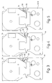
Figur 1 eine Draufsicht auf zwei in ein Druckgerät eingesetzte Bandkassetten;Figur 2 ein Schema der Steuerschaltung des Druckgeräts;Figur 3 einen Satz von Bandkassetten mit einem Bildempfangsband mit 6 mm (oder 12 mm) Breite und einem Bildübertragungsband von 19 mm Breite;Figur 4 einen Satz von Bandkassetten mit einem Bildempfangsband mit 24 mm (oder 32 mm) Breite und einem Bildübertragungsband von 28 mm Breite;Figur 5 einen Satz von Bandkassetten miteinem Bildempfangsband mit 19 mm Breite und einem Bildübertragungsband von entweder 19 mm oder 28 mm Breite;Figur 6 eine Ansicht einer Bandkassette mit Thermo-Direktdruckband; und- Figuren 7A bis 7D und 8A bis 8D illustrieren den Betrieb eines Schalters im Bandkassettenaufnahmeraum.
- Figure 1 is a plan view of two tape cartridges inserted in a printing device;
- Figure 2 is a schematic of the control circuit of the printing device;
- FIG. 3 shows a set of tape cassettes with an image receiving tape with a width of 6 mm (or 12 mm) and an image transfer tape with a width of 19 mm;
- FIG. 4 shows a set of tape cassettes with an image receiving tape with a width of 24 mm (or 32 mm) and an image transfer tape with a width of 28 mm;
- Figure 5 shows a set of tape cassettes with an image receiving tape 19mm wide and an image transfer tape either 19mm or 28mm wide;
- Figure 6 is a view of a tape cassette with thermal direct printing tape; and
- Figures 7A to 7D and 8A to 8D illustrate the operation of a switch in the tape cassette accommodating space.
Figur 1 zeigt die Ansicht eines Banddruckgerätes 1, in dem die vorliegende Erfindung verwendet wird und das zwei darin angeordnete Bandkassetten enthält. Die obere Bandkassette 2 ist in einem ersten Bandkassettenaufnahmebereich 26 angeordnet und enthält einen Vorrat an Bildempfangsband 54, das durch eine Druckzone 3 des Banddruckgerätes 1 zu einem Auslaß 5 des Banddruckgerätes 1 geführt wird. Das Bildempfangsband 54 umfaßt eine obere Schicht zum Empfang eines gedruckten Bildes auf einer seiner Oberflächen, während seine andere Oberfläche mit einer adhäsiven Schicht beschichtet ist, auf die eine abziehbare Rückseitenschicht aufgebracht ist. Die Bandkassette 2 hat einen Einschnitt 6 zur Aufnahme einer Druckwalze 8 des Banddruckgerätes 1, und Führungsabschnitte 22, 24 zum Führen des Bandes 54 durch die Druckzone 3. Die Druckwalze 8 ist innerhalb eines Gußkäfigs 10 drehbar angeordnet. Alternativ kann die Druckwalze 8 drehbar auf einem Stift angeordnet sein.FIG. 1 shows the view of a
Die untere Bandkassette 4 ist innerhalb eines zweiten Bandkassettenaufnahmebereichs 28 angeordnet und enthält als Bildübertragungsband ein Thermotransferfarbband 12, das sich von einer Vorratsspule 30 bis zu einer Aufwickelspule 32 innerhalb der Bandkassette 4 erstreckt. Das Thermotransferband 12 erstreckt sich durch die Druckzone 3 in Überlappung mit dem Bildempfangsband 54. Die Bandkassette 4 hat einen Einschnitt 14 zur Aufnahme eines Druckkopfes 16 des Banddruckgerätes 1 und Führungsabschnitte 34, 36 zum Führen des Thermotransferfarbbandes 12 durch die Druckzone 3. Der Druckkopf 16 ist zwischen einer Betriebsstellung, die in Figur 1 dargestellt ist, in dem er in Kontakt mit der Druckwalze 8 ist und das Thermotransferfarbband 12 und das Bildempfangsband 54 in Überlappung zwischen dem Druckkopf 16 und der Druckwalze 8 hält, und einer Außerbetriebsstellung, in der er von der Druckwalze 8 hinfort bewegt ist, um das Thermotransferfarbband 12 und das Bildempfangsband 54 freizusetzen, beweglich. In der Betriebsstellung wird die Druckwalze 8 rotativ angetrieben, um das Bildempfangsband 54 entlang des Druckkopfes 16 zu transportieren, während der Druckkopf 16 angesteuert wird, durch thermische Übertragung der Tinte des Farbbandes 12 ein Bild auf das Bildempfangsband 54 zu drucken. Der Druckkopf 16 ist ein konventioneller Thermodruckkopf mit einer Reihe von Druckelementen, die entsprechend des gewünschten, auszudruckenden Bildes thermisch aktivierbar sind.The
Das Banddruckgerät 1 hat einen Deckel, der nicht dargestellt ist, jedoch schwenkbar an der Rückseite des Bandkassettenaufnahmeabschnittes 26 befestigt ist und der beide Bandkassetten 2,4 in geschlossenem Zustand überdeckt.The
Ein Motor treibt die Druckwalze 8 an, während aufeinanderfolgend Reihen auf das Bildempfangsband 54 gedruckt werden. Die Druckwalze 8 treibt das Bildempfangsband 4 durch die Druckzone 3 durch die Anwendung ihres Drehmomentes kontinuierlich an. Die Drehung der Druckwalze 8 und die Aktivierung des Druckkopfs 16 werden durch einen Mikroprozessor gesteuert, wie zum Beispiel in unseren Europäischen Patentanmeldungen 0578372 und 0580322 beschrieben ist, deren Inhalt durch Verweis hierin einbezogen wird.A motor drives the
Figur 1 gibt den Stand der Technik wieder, wie er aus EP-A-0573187 bekannt geworden ist. Es ist offensichtlich, daß Bandkassetten 2 mit Bildempfangsband 54 unterschiedlicher Bandparameter beliebig mit Bandkassetten 4 mit Bildübertragungsband 12 unterschiedlicher Bandparameter verwendet werden können, so daß mitunter Fehlbedienungen nicht auszuschließen sind. So kann beispielsweise versehentlich ein sehr breites Bildempfangsband 54 mit einem sehr schmalen Bildübertragungsband 12 eingesetzt werden.Figure 1 represents the prior art as it is known from EP-A-0573187. It is obvious that
Figur 2 zeigt die grundlegende Steuerschaltung zur Steuerung des Banddruckgerätes 1. Es ist ein Mikroprozessorchip 100 vorhanden, der einen Nur-Lese-Speicher (ROM) 102, einen Mikroprozessor 101 und frei zugängliche Speicherkapazität, die durch ein RAM 104 wiedergegeben wird, enthält. Der Mikroprozessor 101 ist mit einem Dateneingabegerät, wie einer Tastatur 106, verbunden, um an ihn eingegebene Daten zu empfangen. Der Mikroprozessorchip 100 gibt Daten zum Treiben eines Displays 108 über einen Displaytreiberchip 109 aus, und auch Daten zum Treiben des Druckkopfs 16 und des Motors 7 zur Steuerung der Druckwalze 8. Der Mikroprozessorchip 100 steuert auch den Schneidemechanismus 17, um Längen bedruckten Bandes abzuschneiden. Die Tastatur und das Display sind an der oberen Oberfläche des Druckgeräts an der rechten Seite des Bandkassettenaufnahmeraums angeordnet, wie durch die gestrichelten Linien angedeutet wird.FIG. 2 shows the basic control circuit for controlling the
Die Bezugsziffer 19 gibt eine Bandkassettendiagnoseeinrichtung wieder, die Schalter in den Bandkassettenaufnahmeräumen zur Detektion verschiedener Bandkassettenbedingungen, wie weiter unten näher beschrieben wird, umfaßt.
Im folgenden wird der Betrieb des Druckers beschrieben. Auszudruckende Daten werden in das Druckgerät unter Verwendung von Dateneingabetasten auf der Tastatur 106 eingegeben. Die Dateneingabetasten sind allgemein durch den Block 109 wiedergegeben, aber werden in der Praxis eine Vielzahl mit Buchstaben versehener und numerierter Tasten umfassen. Wenn die Daten in die Tastatur 106 eingegeben sind, wird der Mikroprozessor mit ihnen beaufschlagt, der das Display 108 betreibt, um die Daten wie eingegeben anzuzeigen. Um das zu tun, ruft der Mikroprozessor für jedes eingegebene Schriftzeichen eine gespeicherte Form des Schriftzeichens aus dem ROM 102 ab. Da das Schriftzeichen in komprimierter Form gespeichert ist, werden diese Fontdaten temporär im RAM 104 gespeichert und durch den Mikroprozessor 100 manupuliert, um zur Erzeugung des Schriftzeichens Pixeldaten herzustellen. Diese Pixeldaten werden in einer Form auf das Display 108 und in anderer Form zum Drucken auf den Druckkopf übertragen. Schriftzeichendaten werden nicht zum Druckkopf übermittelt, solange nicht eine Druckoperation ausgeführt wird. Zunächst werden die Schriftzeichen für das Etikett eingegeben und geändert, wobei Funktionstasten auf der Tastatur 106 in Verbindung mit dem Display 108 verwendet werden.The operation of the printer is described below. Data to be printed is entered into the printing device using data entry keys on the
Wenn die endgültige Form des Etiketts ausgearbeitet ist, sind dem Mikroprozessor die auszudruckenden Pixeldaten bekannt und er hat auch die Gesamtlänge des Etiketts berechnet. Wenn ein Druckvorgang mittels der Druck-Taste 112 initiiert worden ist, wird eine Reihe von Pixel-Daten auf den Druckkopf übertragen, der diese Reihe auf das Bildempfangsband druckt. Der Motor bewegt dann das Bildempfangsband um die Breite einer Reihe vorwärts und die Daten der nächsten Reihe werden auf den Druckkopf übertragen und gedruckt.When the final form of the label has been worked out, the microprocessor knows the pixel data to be printed and has also calculated the total length of the label. When printing is initiated using the
Wenn das gesamte Etikett gedruckt ist, bewegt der Motor das Bildempfangsband über eine Strecke weiter, die der Entfernung zwischen dem Druckkopf und einer Zone, in der ein Schnittvorgang eingerichtet ist, entspricht. Dann wird ein Schneidevorgang durch die Schneideeinrichtung 17 ausgeführt, um den bedruckten Abschnitt des Bandes, der das Etikett bildet, abzuschneiden.When the entire label is printed, the motor moves the image receiving tape a distance that is the distance between the printhead and a zone where a cut is set up. Then, a cutting operation is performed by the
Figur 3 zeigt eine Bandkassette 4a, die der Bandkassette 4 in Figur 1 ähnelt. Analog offenbart Figur 3 außerdem eine Bandkassette 2a, die der Bandkassette 2 in Figur 1 ähnelt. Die Bandkassette 4a ist im wesentlichen dieselbe als die in Bezug zur Figur 1 beschriebene, umfaßt aber ein Verriegelungselement 50, das sich vom Gehäuse der Bandkassette 4a ausdehnt. Das Verriegelungselement 50 endet in einem hakenförmigen Abschnitt 52.FIG. 3 shows a
Die Bandkassette 2a ist ähnlich der in Bezug auf Figur 1 beschriebenen, enthält aber in ihrem Gehäuse einen Einschnitt 54, der zur Aufnahme des hakenförmigen Abschnitts 52 bemessen ist. Der Einschnitt 54 hat eine Kante 56, oberhalb der der hakenförmige Abschnitt 52 des Verriegelungselements 50 angeordnet ist. In Figur 3 hat das Bildübertragungsband eine Breite von 19 mm und das Bildempfangsband eine Breite von 6 mm oder 12 mm. Das Verriegelungselement 50 wirkt mit dem Einschnitt 54 zusammen, um ein Zusammenwirken dieser Bandkassetten im Druckgerät zu ermöglichen.The
Figur 4 illustriert einen anderen Satz von Bandkassetten. Die in Figur 4 gezeigte Bandkassette 4b ist der Bandkassette 4a ähnlich, mit der Ausnahme, daß sie Bildübertragüngsband einer größeren Breite von z.B. 28 mm enthält. Sie ist auch mit einem Veriegelungselement 58 versehen, das einen hakenförmigen Abschnitt 60 aufweist, der näher an der Oberfläche der Bandkassette 4b als der hakenförmige Abschnitt 52 des Verriegelungselements 50 in Figur 3 ist.Figure 4 illustrates another set of tape cartridges. The
Die Bandkassette 2b ist ähnlich der Bandkassette 2a der Figur 3, enthält aber ein Bildempfangsband einer größeren Breite, zum Beispiel 24 mm oder 32 mm. Die Bandkassette 2b hat einen Einschnitt 62, der das Verriegelungselement 58 aufnimmt, der jedoch keine Kante definiert. Auf diese Art wird dem Satz von Bandkassetten der Figur 4 erlaubt, zusammenzuwirken.The
Es ist jedoch bereits erkennbar, daß, wenn ein Versuch gemacht würde, eine Bandkassette 4b in ein Druckgerät einzusetzen, das eine Bandkassette 2a (geringer Breite des Bandes) enthält, der hakenförmige Abschnitt 60 des Verriegelungselements 58 mit der Kante 56 des Einschnitts interferieren und somit nicht erlauben würde, die Bandkassette einzusetzen. Ähnlich würde das Verriegelungselement 50 nicht in den Einschnitt 60 passen, wenn der Versuch gemacht würde, eine Bandkassette 4a mit geringer Breite des Bandes in ein Druckgerät einzusetzen, das eine Bandkassette mit Band größerer Breite enthält, und daher würden die Bandkassetten nicht zusammenwirken. Somit ist die Möglichkeit der Auswahl der falschen Breite des Bildübertragungsbandes für das gewählte Bildempfangsband unterbunden.However, it can already be seen that if an attempt were made to insert a
Figur 5 zeigt einen Satz von Bandkassetten, wobei die Bandkassette ein Bildempfangsband einer Breite von 19 mm enthält. Dieses könnte ohne Schwierigkeit mit einem Bildübertragungsband einer Breite von 19 mm oder 28 mm zusammenwirken. Somit enthält die Bandkassette 2c einen sogenannten Doppel-Einschnitt 64. Dieser Doppel-Einschnitt 64 wird sowohl das Verriegelungselement 58 der Bandkassette 4b als auch das Verriegelungselement 50 der Bandkassette 4a aufnehmen. Um dieses wiederzugeben, ist die Bandkassette mit Bildübertragungsband in Figur 5 mit 4a/b gekennzeichnet. Dies zeigt an, daß jede der Bandkassetten ordnungsgemäß mit einer Bandkassette 2c mit einer Breite des Bandes von 19 mm zusammenwirken könnte.FIG. 5 shows a set of tape cassettes, the tape cassette containing an
Daher ist auf eine sehr einfache Weise die Möglichkeit, die falsche Breite eines Bildübertragungsbandes mit einer falschen Breite eines Bildempfangsbandes in einem Druckgerät zu benutzen, unterbunden.Therefore, the possibility of using the wrong width of an image transmission belt with an incorrect width of an image reception belt in a printing device is prevented in a very simple manner.
Figur 6 illustriert eine Bandkassette 2d, die Thermo-Direktdruckband enthält. Die Bandkassette hat einen verlängerten Abschnitt 60, der sich bis in den zweiten Bandkassettenaufnahmebereich 28 ausdehnt, wenn die Bandkassette 2d in den ersten Bandkassettenaufnahmebereich 26 eingesetzt ist. Somit ist es physikalisch nicht möglich, eine Bandkassette in den zweiten Bandkassettenaufnahmebereich einzusetzen, wenn eine Bandkassette mit Thermo-Direktdruckband eingesetzt ist.Figure 6 illustrates a
Eine Bandkassette 2d mit Thermo-Direktdruckband hat einen Betätiger 62 zum Betätigen eines Schaltmechanismus im ersten Bandkassettenaufnahmebereich 26, um bekanntzugeben, daß ein Thermo-Direktdruckband eingelegt ist. Der Schaltmechanismus im ersten Bandkassettenaufnahmebereich 26 ist in der Bandkassettendiagnoseeinrichtung 19 enthalten. Ein Signal wird an die Steuerung 100 gesandt, um anzuzeigen, daß eine Bandkassette mit Thermo-Direktdruckband eingelegt ist, und die Steuerung ändert die Druckenergie für der Druckkopf 16 entsprechend. Wenn nötig, können weitere Änderungen des Betriebs des Druckgeräts gemacht werden.A
Ein anderer Aspekt der Bandkassette 2d der Figur 6 wird nun mit Verweis auf die Figuren 7a bis 7d und 8a bis 8d erläutert. In einem bekannten Druckgerät, das in der EP-A-0607023 beschrieben ist, stellt ein im zweiten Bandkassettenaufnahmebereich angeordneter Schalter fest, wenn ein Deckel des Druckgeräts geschlossen ist und wenn eine Bandkassette mit Bildübertragungsband vorhanden ist, so daß das Gerät nur arbeitet, wenn beide Kriterien erfüllt sind. Ein derartiges Gerät würde somit nicht arbeiten, wenn keine Bandkassette mit Bildübertragungsband eingesetzt wäre. Dieses Problem wird dadurch gelöst, daß die Bandkassette 2d mit Thermo-Direktdruckband ebenfalls so gestaltet ist, daß sie denselben Schalter betätigt, so daß es der Steuerung 100 den Anschein gibt, daß eine Bandkassette mit Bildübertragungsband vorhanden ist, so daß das Gerät arbeitet.Another aspect of the
Im folgenden wird ein derartiger Schalter mit seinem Betätigungsmechanismus beschrieben.Such a switch with its actuating mechanism is described below.
Der Schalter wird allgemein mit der Bezugsziffer 202 (Figur 8a) bezeichnet. Er wird von einem Druckkopfarm 204 getragen, der auch den Druckkopf 16 trägt. Der Druckkopfarm ist am Deckel 206 des Druckgeräts über einen Betätigungsmechanismus 208 befestigt, dessen Einzelheiten hier nicht wiedergegeben werden. Kurzgefaßt wird der Druckkopf in seine Außerbetriebsstellung verbracht, wenn der Deckel geöffnet ist. Wenn der Deckel geschlossen ist, wird der Druckkopf in seine Betriebsstellung gebracht. Da der Druckkopfarm 204 sich zwischen der Betriebsstellung und der Außerbetriebsstellung bewegt, bewegt sich der Schalter mit ihm. Das Bezugszeichen 210 gibt einen Schalterbetätiger wieder, der am Boden des zweiten Bandkassettenaufnahmeraums angeordnet ist. Die Figuren 7a und 8a illustrieren die Lage, wenn der Deckel offen und keine Bandkassette mit Bildübertragungsband eingesetzt ist.The switch is generally designated by reference numeral 202 (Figure 8a). It is carried by a
Figuren 7b und 8b geben die Lage wieder, wenn der Deckel 206 geschlossen ist und noch keine Bandkassette mit Bildübertragungsband vorhanden ist. In dieser Situation hat sich die Lage des Schalters 202 mit dem Druckkopfarm 204 geändert, jedoch stehen sind die Kontakte noch nicht in Berührung. Somit bleibt der Schalter 202 offen und die Steuerung 100 erlaubt dem Gerät nicht, zu arbeiten.FIGS. 7b and 8b show the position when the
Figuren 7c und 8c stellen die Situation dar, wenn eine Bandkassette mit Bildübertragungsband in den zweiten Bandkassettenaufnahmebereich eingesetzt ist, wobei der Deckel 206 in der offenen Position ist. Die Bandkassette kann eine Bandkassette mit Bildübertragungsband oder eine Bandkassette 2d mit Direkt-Thermodruckband sein, wobei der verlängerte Abschnitt 60 auf den Schalterbetätiger 210 einwirkt.Figures 7c and 8c illustrate the situation when a tape cassette with image transfer tape is inserted in the second tape cassette receiving area with the
In dieser Lage wird der Schalterbetätiger 210 elastisch zur rechten Seite in Figur 7c bewegt, um ihn in eine Lage zu bringen, in der er nunmehr eine Bewegung des Schalters 202 zu weit nach links in Figur 8c unterbindet. In Figur 8c ist der Deckel 206 offen und daher die Kontakte des Schalters 202 nicht geschlossen. Wie jedoch in den Figuren 7d und 8d erkennbar ist, wird der Schalter 202 derart bewegt, daß er gegen den Schalterbetätiger 210 stößt, so daß die Kontakte des Schalters 202 geschlossen sind, wenn der Deckel 206 geschlossen wird und sich der Druckkopfarm 204 bewegt. In dieser Stellung wird das Druckgerät arbeiten.In this position, the
Claims (15)
einem zweiten Bandkassettenaufnahmebereich (28) zur Aufnahme einer zweiten Bandkassette (4a, 4b), die einen Vorrat an Bildübertragungsband (12) zum Drucken eines Bildes enthält,
Mitteln (8) zum Bewegen des Bildempfangsbandes (54) durch eine Druckzone (3) in Überlagerung mit dem Bildübertragungsband (12), so daß ein Bild vom Bildübertragungsband (12) auf das Bildempfangsband (54) übertragbar ist, dadurch gekennzeichnet, daß die erste und zweite Bandkassette jeweils derart aus ersten und zweiten Gruppen auswählbar sind, daß sie einzeln entfernbar und ersetzbar sind, wobei die Gruppen einen Satz von Bandkassetten nach einem der vorhergehenden Ansprüche bilden.Thermal printing device (1) with a first tape cassette receiving area (26) for receiving a first tape cassette (2a, 2b, 2c) which contains a supply of image receiving tape (54),
a second tape cassette receiving area (28) for receiving a second tape cassette (4a, 4b) containing a supply of image transfer tape (12) for printing an image,
Means (8) for moving the image receiving belt (54) through a printing zone (3) in superimposition with the image transfer belt (12) so that an image from the image transmission belt (12) can be transferred to the image receiving belt (54), characterized in that the first and the second tape cassette can each be selected from first and second groups such that they can be individually removed and replaced, the groups forming a set of tape cassettes according to one of the preceding claims.
einem ersten Bandkassettenaufnahmebereich (26) zur Aufnahme einer ersten Bandkassette (2a, 2b, 2c, 2d), die einen Vorrat an Bildempfangsband (54), das mit einem Bild zu bedrucken ist, enthält;
einem zweiten Bandkassettenaufnahmebereich (28) zur Aufnahme einer zweiten Bandkassette (4a, 4b), die einen Vorrat an Bildübertragungsband (12) enthält;
Mitteln (8) zum Bewegen des Bildempfangsbandes (54) durch eine Druckzone (3), in der ein Thermodruckmechanismus (16) zum Drucken eines Bildes auf das Bildempfangsband (54) arbeitet, dadurch gekennzeichnet, daß die erste Bandkassette aus einem Satz von Bandkassetten (2a, 2b, 2c, 2d) auswählbar ist, die zumindest eine Bandkassette (2d) umfassen, die einen Vorrat an Thermo-Direktdruckband enthält, wobei die Bandkassette (2d) mit Thermo-Direktdruckband derart geformt ist, daß sie das Einsetzen einer zweiten Bandkassette (4a, 4b) in den zweiten Bandkassettenaufnahmebereich (28) ausschließt; und
daß der erste Bandkassettenaufnahmebereich (26) Mittel (19) zur Detektion, daß eine erste Bandkassette (2d) mit Thermo-Direktdruckband eingesetzt ist, umfaßt.Thermal printing device with
a first tape cassette receiving area (26) for receiving a first tape cassette (2a, 2b, 2c, 2d) containing a supply of image receiving tape (54) to be printed with an image;
a second tape cassette receiving area (28) for receiving a second tape cassette (4a, 4b) containing a supply of image transfer tape (12);
Means (8) for moving the image receiving tape (54) through a printing zone (3) in which a thermal printing mechanism (16) operates for printing an image on the image receiving tape (54), characterized in that the first tape cassette consists of a set of tape cassettes ( 2a, 2b, 2c, 2d) can be selected, which comprise at least one tape cassette (2d) which contains a supply of direct thermal printing tape, the tape cassette (2d) being shaped with direct thermal printing tape in such a way that it does Excludes insertion of a second tape cassette (4a, 4b) into the second tape cassette receiving area (28); and
that the first tape cassette receiving area (26) comprises means (19) for detecting that a first tape cassette (2d) with thermal direct printing tape is inserted.
Priority Applications (2)
| Application Number | Priority Date | Filing Date | Title |
|---|---|---|---|
| EP01106197A EP1106367B8 (en) | 1995-11-10 | 1996-09-19 | Set of tape cartridges and printing apparatus |
| DE59611319T DE59611319D1 (en) | 1995-11-10 | 1996-09-19 | Set of tape cassettes and printing device |
Applications Claiming Priority (4)
| Application Number | Priority Date | Filing Date | Title |
|---|---|---|---|
| GB9523053 | 1995-11-10 | ||
| GBGB9523053.8A GB9523053D0 (en) | 1995-11-10 | 1995-11-10 | Thermal printing device |
| GB9614125 | 1996-07-05 | ||
| GB9614125A GB2306917B (en) | 1995-11-10 | 1996-07-05 | Thermal printing device with direct thermal cassette |
Related Child Applications (2)
| Application Number | Title | Priority Date | Filing Date |
|---|---|---|---|
| EP01106197A Division EP1106367B8 (en) | 1995-11-10 | 1996-09-19 | Set of tape cartridges and printing apparatus |
| EP01106197.5 Division-Into | 2001-03-14 |
Publications (3)
| Publication Number | Publication Date |
|---|---|
| EP0773110A2 true EP0773110A2 (en) | 1997-05-14 |
| EP0773110A3 EP0773110A3 (en) | 1998-08-26 |
| EP0773110B1 EP0773110B1 (en) | 2002-04-03 |
Family
ID=26308089
Family Applications (1)
| Application Number | Title | Priority Date | Filing Date |
|---|---|---|---|
| EP96114988A Expired - Lifetime EP0773110B1 (en) | 1995-11-10 | 1996-09-19 | Set of tape cartridges and printing apparatus |
Country Status (3)
| Country | Link |
|---|---|
| US (1) | US5857788A (en) |
| EP (1) | EP0773110B1 (en) |
| DE (1) | DE59608999D1 (en) |
Cited By (3)
| Publication number | Priority date | Publication date | Assignee | Title |
|---|---|---|---|---|
| EP0958927A1 (en) * | 1998-04-23 | 1999-11-24 | Esselte N.V. | Tape printing apparatus and tape cassette |
| WO2004058507A1 (en) | 2002-12-24 | 2004-07-15 | Esselte | Identifying compatible combination for a thermal printer |
| CN105517806A (en) * | 2013-08-30 | 2016-04-20 | 普利麦罗技术公司 | Cassette printer with picker |
Families Citing this family (14)
| Publication number | Priority date | Publication date | Assignee | Title |
|---|---|---|---|---|
| GB2318094A (en) * | 1996-10-14 | 1998-04-15 | Esselte Nv | Tape cassette with tape printing apparatus |
| US6102590A (en) * | 1998-03-12 | 2000-08-15 | International Business Machines Corporation | Cover-platen opening mechanism |
| EP2202082B1 (en) | 2008-12-25 | 2012-02-15 | Brother Kogyo Kabushiki Kaisha | Tape printer |
| KR20150038644A (en) | 2008-12-25 | 2015-04-08 | 브라더 고오교오 가부시키가이샤 | Tape cassette |
| EP2415610B1 (en) | 2009-03-31 | 2019-07-03 | Brother Kogyo Kabushiki Kaisha | Tape cassette |
| CN201989425U (en) | 2009-03-31 | 2011-09-28 | 兄弟工业株式会社 | Band box and band printer |
| WO2010113441A1 (en) | 2009-03-31 | 2010-10-07 | Brother Kogyo Kabushiki Kaisha | Tape cassette and tape printer |
| JP5136503B2 (en) | 2009-03-31 | 2013-02-06 | ブラザー工業株式会社 | Tape cassette |
| EP2415612B1 (en) | 2009-03-31 | 2019-09-25 | Brother Kogyo Kabushiki Kaisha | Tape cassette |
| US8641304B2 (en) | 2009-06-30 | 2014-02-04 | Brother Kogyo Kabushiki Kaisha | Tape cassette |
| JP5212550B2 (en) | 2009-12-16 | 2013-06-19 | ブラザー工業株式会社 | Tape cassette |
| WO2011080840A1 (en) | 2009-12-28 | 2011-07-07 | ブラザー工業株式会社 | Tape cassette |
| JP6329096B2 (en) * | 2015-03-19 | 2018-05-23 | セイコーエプソン株式会社 | Tape cartridge |
| JP7035713B2 (en) * | 2018-03-29 | 2022-03-15 | セイコーエプソン株式会社 | Ribbon cartridge |
Citations (5)
| Publication number | Priority date | Publication date | Assignee | Title |
|---|---|---|---|---|
| GB2161754A (en) * | 1984-07-18 | 1986-01-22 | K Sun Corp | Two-piece tape/ribbon cartridge |
| EP0573187A1 (en) * | 1992-06-01 | 1993-12-08 | Esselte Dymo N.V. | Thermal printing device |
| EP0607025A2 (en) * | 1993-01-14 | 1994-07-20 | Esselte Dymo N.V. | Printing apparatus with cassette |
| EP0625427A2 (en) * | 1993-05-19 | 1994-11-23 | Brother Kogyo Kabushiki Kaisha | Tape cassette |
| EP0634274A2 (en) * | 1993-07-12 | 1995-01-18 | Esselte Dymo N.V. | Printing apparatus |
Family Cites Families (16)
| Publication number | Priority date | Publication date | Assignee | Title |
|---|---|---|---|---|
| US4901090A (en) * | 1987-04-13 | 1990-02-13 | Hitachi, Ltd. | Inked sheet cassette and thermal transfer-type recording apparatus |
| US5009530A (en) * | 1987-10-31 | 1991-04-23 | Brother Kogyo Kabushiki Kaisha | Apparatus for reverse recording image and covering by protective medium |
| US5111216A (en) * | 1988-07-12 | 1992-05-05 | Kroy Inc. | Tape supply cartridge for portable thermal printer |
| EP0354815B1 (en) * | 1988-08-12 | 1994-04-20 | Esselte Meto International Produktions Gmbh | Improvements relating to printing systems |
| US5028934A (en) * | 1988-10-31 | 1991-07-02 | Seiko Epson Corporation | Hand-held portable printing system |
| US5183333A (en) * | 1990-04-11 | 1993-02-02 | Seiko Epson Corporation | Printer system for selective printing on first and second print media located in separate print zones |
| GB2250716A (en) * | 1990-11-20 | 1992-06-17 | Esselte Dymo Nv | Lid-responsive release of thermal printhead in printer using cassetted ink-ribbon. |
| JP2596263B2 (en) * | 1991-07-22 | 1997-04-02 | ブラザー工業株式会社 | Tape cassette manufacturing method and tape cassette |
| JPH05221064A (en) * | 1992-02-07 | 1993-08-31 | Brother Ind Ltd | Tape cassette for printing normal image |
| JP3353788B2 (en) * | 1992-06-05 | 2002-12-03 | ブラザー工業株式会社 | Printing equipment |
| US5358351A (en) * | 1992-09-30 | 1994-10-25 | Casio Computer Co., Ltd. | Printing apparatus and printing tape cassette used therefor |
| JP2927146B2 (en) * | 1993-06-15 | 1999-07-28 | ブラザー工業株式会社 | Tape cassette |
| JP3335433B2 (en) * | 1993-07-07 | 2002-10-15 | ブラザー工業株式会社 | Tape cassette |
| DE69420941T2 (en) * | 1993-12-29 | 2000-02-03 | Brother Ind Ltd | Strip printer |
| JP2976823B2 (en) * | 1994-09-28 | 1999-11-10 | ブラザー工業株式会社 | Cassette case and tape case for making printing tape |
| US5454659A (en) * | 1994-10-14 | 1995-10-03 | Quickie Manufacturing Corporation | Liquid dispensing implement |
-
1996
- 1996-09-19 DE DE59608999T patent/DE59608999D1/en not_active Expired - Lifetime
- 1996-09-19 EP EP96114988A patent/EP0773110B1/en not_active Expired - Lifetime
- 1996-11-08 US US08/747,125 patent/US5857788A/en not_active Expired - Lifetime
Patent Citations (5)
| Publication number | Priority date | Publication date | Assignee | Title |
|---|---|---|---|---|
| GB2161754A (en) * | 1984-07-18 | 1986-01-22 | K Sun Corp | Two-piece tape/ribbon cartridge |
| EP0573187A1 (en) * | 1992-06-01 | 1993-12-08 | Esselte Dymo N.V. | Thermal printing device |
| EP0607025A2 (en) * | 1993-01-14 | 1994-07-20 | Esselte Dymo N.V. | Printing apparatus with cassette |
| EP0625427A2 (en) * | 1993-05-19 | 1994-11-23 | Brother Kogyo Kabushiki Kaisha | Tape cassette |
| EP0634274A2 (en) * | 1993-07-12 | 1995-01-18 | Esselte Dymo N.V. | Printing apparatus |
Cited By (6)
| Publication number | Priority date | Publication date | Assignee | Title |
|---|---|---|---|---|
| EP0958927A1 (en) * | 1998-04-23 | 1999-11-24 | Esselte N.V. | Tape printing apparatus and tape cassette |
| US6092946A (en) * | 1998-04-23 | 2000-07-25 | Esselte Nv | Tape printing apparatus and tape holding case with a sliding switch |
| WO2004058507A1 (en) | 2002-12-24 | 2004-07-15 | Esselte | Identifying compatible combination for a thermal printer |
| CN100377888C (en) * | 2002-12-24 | 2008-04-02 | 迪默公司 | Identifying compatible combination for a thermal printer |
| CN105517806A (en) * | 2013-08-30 | 2016-04-20 | 普利麦罗技术公司 | Cassette printer with picker |
| CN105517806B (en) * | 2013-08-30 | 2018-06-12 | 普利麦罗技术公司 | Box printer with picker |
Also Published As
| Publication number | Publication date |
|---|---|
| US5857788A (en) | 1999-01-12 |
| EP0773110A3 (en) | 1998-08-26 |
| EP0773110B1 (en) | 2002-04-03 |
| DE59608999D1 (en) | 2002-05-08 |
Similar Documents
| Publication | Publication Date | Title |
|---|---|---|
| EP0941850B1 (en) | Control device for the printing of one or more webs in a rotary printing device and corresponding rotary printing device | |
| EP0773110B1 (en) | Set of tape cartridges and printing apparatus | |
| DE102009059954B4 (en) | Tape cassette and tape printer | |
| DE2820266C3 (en) | Ink and correction tape guides for typewriters and the like | |
| DE60104910T2 (en) | print Setup | |
| DE4022696A1 (en) | METHOD AND DEVICE FOR FORMING RECORDS BY MEANS OF A MULTICOLOR RIBBON | |
| DE102009059956A1 (en) | Tape cassette and tape printer | |
| DE3425951A1 (en) | IMAGE GENERATION DEVICE | |
| DE3108367A1 (en) | PRINTER | |
| DE3725334A1 (en) | DOT PRINTER | |
| DE19710719A1 (en) | Thermal printing process and thermal printer for executing the process | |
| EP0807525B1 (en) | Cutting device | |
| DE602004007204T2 (en) | Tape printer and tape printing system | |
| DE19614080C2 (en) | Thermal printer | |
| DE60308986T2 (en) | Tape printing apparatus | |
| EP0761454B1 (en) | Tape printing apparatus | |
| EP1106367B1 (en) | Set of tape cartridges and printing apparatus | |
| DE4236999C2 (en) | Multiple printing device for multiple printing on the same printing surface of a recording medium | |
| EP0958927B1 (en) | Tape printing apparatus and tape cassette | |
| EP0855282B1 (en) | Tape printing device | |
| DE69629619T2 (en) | Printer with removable print head | |
| DE69601774T3 (en) | Label tape printer | |
| EP0885733B1 (en) | Process for operating a label printing system | |
| EP0807524B1 (en) | Printing apparatus with an automatic cutting device | |
| EP0785078A2 (en) | Tape printer drive |
Legal Events
| Date | Code | Title | Description |
|---|---|---|---|
| PUAI | Public reference made under article 153(3) epc to a published international application that has entered the european phase |
Free format text: ORIGINAL CODE: 0009012 |
|
| AK | Designated contracting states |
Kind code of ref document: A2 Designated state(s): CH DE FR GB LI |
|
| PUAL | Search report despatched |
Free format text: ORIGINAL CODE: 0009013 |
|
| AK | Designated contracting states |
Kind code of ref document: A3 Designated state(s): CH DE FR GB LI |
|
| 17P | Request for examination filed |
Effective date: 19980714 |
|
| 17Q | First examination report despatched |
Effective date: 19990810 |
|
| GRAG | Despatch of communication of intention to grant |
Free format text: ORIGINAL CODE: EPIDOS AGRA |
|
| GRAG | Despatch of communication of intention to grant |
Free format text: ORIGINAL CODE: EPIDOS AGRA |
|
| GRAH | Despatch of communication of intention to grant a patent |
Free format text: ORIGINAL CODE: EPIDOS IGRA |
|
| REG | Reference to a national code |
Ref country code: GB Ref legal event code: IF02 |
|
| GRAH | Despatch of communication of intention to grant a patent |
Free format text: ORIGINAL CODE: EPIDOS IGRA |
|
| GRAA | (expected) grant |
Free format text: ORIGINAL CODE: 0009210 |
|
| AK | Designated contracting states |
Kind code of ref document: B1 Designated state(s): CH DE FR GB LI |
|
| REG | Reference to a national code |
Ref country code: CH Ref legal event code: EP |
|
| GBT | Gb: translation of ep patent filed (gb section 77(6)(a)/1977) |
Effective date: 20020403 |
|
| REF | Corresponds to: |
Ref document number: 59608999 Country of ref document: DE Date of ref document: 20020508 |
|
| REG | Reference to a national code |
Ref country code: CH Ref legal event code: NV Representative=s name: BOVARD AG PATENTANWAELTE |
|
| ET | Fr: translation filed | ||
| PLBE | No opposition filed within time limit |
Free format text: ORIGINAL CODE: 0009261 |
|
| STAA | Information on the status of an ep patent application or granted ep patent |
Free format text: STATUS: NO OPPOSITION FILED WITHIN TIME LIMIT |
|
| 26N | No opposition filed |
Effective date: 20030106 |
|
| REG | Reference to a national code |
Ref country code: CH Ref legal event code: PFA Owner name: ESSELTE Free format text: ESSELTE N.V.#INDUSTRIEPARK NOORD 30, P.O. BOX 85#9100 ST. NIKLAAS (BE) -TRANSFER TO- ESSELTE#INDUSTRIEPARK NOORD 30 P.O. BOX 86#9100 SINT-NIKLAAS (BE) |
|
| REG | Reference to a national code |
Ref country code: CH Ref legal event code: PFA Owner name: DYMO Free format text: ESSELTE#INDUSTRIEPARK NOORD 30 P.O. BOX 86#9100 SINT-NIKLAAS (BE) -TRANSFER TO- DYMO#INDUSTRIEPARK NOORD 30 P.O. BOX 86#9100 SINT-NIKLAAS (BE) |
|
| REG | Reference to a national code |
Ref country code: FR Ref legal event code: CD |
|
| PGFP | Annual fee paid to national office [announced via postgrant information from national office to epo] |
Ref country code: DE Payment date: 20100915 Year of fee payment: 15 |
|
| REG | Reference to a national code |
Ref country code: CH Ref legal event code: PFA Owner name: DYMO Free format text: DYMO#INDUSTRIEPARK NOORD 30 P.O. BOX 86#9100 SINT-NIKLAAS (BE) -TRANSFER TO- DYMO#INDUSTRIEPARK NOORD 30 P.O. BOX 86#9100 SINT-NIKLAAS (BE) |
|
| PGFP | Annual fee paid to national office [announced via postgrant information from national office to epo] |
Ref country code: CH Payment date: 20110913 Year of fee payment: 16 |
|
| PGFP | Annual fee paid to national office [announced via postgrant information from national office to epo] |
Ref country code: GB Payment date: 20110914 Year of fee payment: 16 Ref country code: FR Payment date: 20110922 Year of fee payment: 16 |
|
| PG25 | Lapsed in a contracting state [announced via postgrant information from national office to epo] |
Ref country code: DE Free format text: LAPSE BECAUSE OF NON-PAYMENT OF DUE FEES Effective date: 20120403 |
|
| REG | Reference to a national code |
Ref country code: DE Ref legal event code: R119 Ref document number: 59608999 Country of ref document: DE Effective date: 20120403 |
|
| REG | Reference to a national code |
Ref country code: CH Ref legal event code: PL |
|
| GBPC | Gb: european patent ceased through non-payment of renewal fee |
Effective date: 20120919 |
|
| REG | Reference to a national code |
Ref country code: FR Ref legal event code: ST Effective date: 20130531 |
|
| PG25 | Lapsed in a contracting state [announced via postgrant information from national office to epo] |
Ref country code: GB Free format text: LAPSE BECAUSE OF NON-PAYMENT OF DUE FEES Effective date: 20120919 Ref country code: LI Free format text: LAPSE BECAUSE OF NON-PAYMENT OF DUE FEES Effective date: 20120930 Ref country code: CH Free format text: LAPSE BECAUSE OF NON-PAYMENT OF DUE FEES Effective date: 20120930 |
|
| PG25 | Lapsed in a contracting state [announced via postgrant information from national office to epo] |
Ref country code: FR Free format text: LAPSE BECAUSE OF NON-PAYMENT OF DUE FEES Effective date: 20121001 |