EP0772055B1 - Système de contrôle de la phase de décharge des cycles de charge-décharge d'une batterie rechargeable, et dispositif hôte muni d'une batterie intelligente - Google Patents
Système de contrôle de la phase de décharge des cycles de charge-décharge d'une batterie rechargeable, et dispositif hôte muni d'une batterie intelligente Download PDFInfo
- Publication number
- EP0772055B1 EP0772055B1 EP96202927A EP96202927A EP0772055B1 EP 0772055 B1 EP0772055 B1 EP 0772055B1 EP 96202927 A EP96202927 A EP 96202927A EP 96202927 A EP96202927 A EP 96202927A EP 0772055 B1 EP0772055 B1 EP 0772055B1
- Authority
- EP
- European Patent Office
- Prior art keywords
- instant
- discharge
- battery
- neural network
- initial
- Prior art date
- Legal status (The legal status is an assumption and is not a legal conclusion. Google has not performed a legal analysis and makes no representation as to the accuracy of the status listed.)
- Expired - Lifetime
Links
Images


Classifications
-
- H—ELECTRICITY
- H02—GENERATION; CONVERSION OR DISTRIBUTION OF ELECTRIC POWER
- H02J—CIRCUIT ARRANGEMENTS OR SYSTEMS FOR SUPPLYING OR DISTRIBUTING ELECTRIC POWER; SYSTEMS FOR STORING ELECTRIC ENERGY
- H02J7/00—Circuit arrangements for charging or depolarising batteries or for supplying loads from batteries
- H02J7/0063—Circuit arrangements for charging or depolarising batteries or for supplying loads from batteries with circuits adapted for supplying loads from the battery
-
- G—PHYSICS
- G01—MEASURING; TESTING
- G01R—MEASURING ELECTRIC VARIABLES; MEASURING MAGNETIC VARIABLES
- G01R19/00—Arrangements for measuring currents or voltages or for indicating presence or sign thereof
- G01R19/165—Indicating that current or voltage is either above or below a predetermined value or within or outside a predetermined range of values
- G01R19/16566—Circuits and arrangements for comparing voltage or current with one or several thresholds and for indicating the result not covered by subgroups G01R19/16504, G01R19/16528, G01R19/16533
- G01R19/16576—Circuits and arrangements for comparing voltage or current with one or several thresholds and for indicating the result not covered by subgroups G01R19/16504, G01R19/16528, G01R19/16533 comparing DC or AC voltage with one threshold
-
- G—PHYSICS
- G01—MEASURING; TESTING
- G01R—MEASURING ELECTRIC VARIABLES; MEASURING MAGNETIC VARIABLES
- G01R31/00—Arrangements for testing electric properties; Arrangements for locating electric faults; Arrangements for electrical testing characterised by what is being tested not provided for elsewhere
- G01R31/36—Arrangements for testing, measuring or monitoring the electrical condition of accumulators or electric batteries, e.g. capacity or state of charge [SoC]
- G01R31/367—Software therefor, e.g. for battery testing using modelling or look-up tables
-
- G—PHYSICS
- G01—MEASURING; TESTING
- G01R—MEASURING ELECTRIC VARIABLES; MEASURING MAGNETIC VARIABLES
- G01R31/00—Arrangements for testing electric properties; Arrangements for locating electric faults; Arrangements for electrical testing characterised by what is being tested not provided for elsewhere
- G01R31/36—Arrangements for testing, measuring or monitoring the electrical condition of accumulators or electric batteries, e.g. capacity or state of charge [SoC]
- G01R31/382—Arrangements for monitoring battery or accumulator variables, e.g. SoC
- G01R31/3835—Arrangements for monitoring battery or accumulator variables, e.g. SoC involving only voltage measurements
-
- G—PHYSICS
- G01—MEASURING; TESTING
- G01R—MEASURING ELECTRIC VARIABLES; MEASURING MAGNETIC VARIABLES
- G01R31/00—Arrangements for testing electric properties; Arrangements for locating electric faults; Arrangements for electrical testing characterised by what is being tested not provided for elsewhere
- G01R31/36—Arrangements for testing, measuring or monitoring the electrical condition of accumulators or electric batteries, e.g. capacity or state of charge [SoC]
- G01R31/396—Acquisition or processing of data for testing or for monitoring individual cells or groups of cells within a battery
-
- G—PHYSICS
- G06—COMPUTING OR CALCULATING; COUNTING
- G06N—COMPUTING ARRANGEMENTS BASED ON SPECIFIC COMPUTATIONAL MODELS
- G06N3/00—Computing arrangements based on biological models
- G06N3/02—Neural networks
- G06N3/04—Architecture, e.g. interconnection topology
- G06N3/045—Combinations of networks
-
- G—PHYSICS
- G06—COMPUTING OR CALCULATING; COUNTING
- G06N—COMPUTING ARRANGEMENTS BASED ON SPECIFIC COMPUTATIONAL MODELS
- G06N3/00—Computing arrangements based on biological models
- G06N3/02—Neural networks
- G06N3/08—Learning methods
Definitions
- the invention relates to a system for controlling the phase of discharge of charge-discharge cycles of a battery rechargeable, to form a smart battery.
- the invention also relates to a host device equipped of a smart battery.
- the invention finds its application in the field of modular devices equipped with a rechargeable battery such that for example: individual cell phones or professionals, cordless tools, computers laptops, toys ....
- smart battery we generally mean a rechargeable battery, coupled to a system that controls its amount of charge.
- This system includes means for collect data on the amount of charge the battery, and means for providing information calculated predictions regarding discharge conditions in the future.
- a technical problem posed by determination predictive information on discharge conditions in the future for a rechargeable battery is variability of battery construction parameters and the variability of the habits of the user of the device host.
- the variability of the construction parameters of the battery considered individually is due to dispersion structure data in manufacturing towers, for the same Battery Type.
- a charge quantity control system for a battery, using a neural network is already known to the publication titled "Neural Network, A proper Approach to the Energy Management Problem ", by Marcus STOLL in” 10th European Photovoltaic Solar Energy conference ", 8-10 APRIL 1991, LISBON, PORTUGAL, p.427-430 ".
- the publication cited describes the use of a neural network to assume the task of estimating the amount of charge (SOC) of a battery lead-acid, in a recharging system (RES).
- RES recharging system
- determining the amount of charge (SOC) is an important task to be performed to control the energy level of a battery.
- the estimation of the amount of charge allows planning of the use of renewable energy, the optimization of conditions of use of a host device, taking decisions concerning the different phases of the cycles of charge-discharge of the battery.
- a neural network is trained by means of a base of data, to estimate the amount of charge (SOC).
- the neural network is trained on only a small part of the discharge domain of the drums. As, for most of the time, the discharge current is very small, the network drive of neurons is performed in this area.
- this base of data may include information relating to the cycles of discharge and depth of discharge and at average temperature drums. Different batches of this data, forming input vectors, are supplied to the neural network for it learn the discharge behavior of the batteries.
- the network of neurons is organized for an appropriate representation of the battery behavior.
- a problem resulting from the use of the known system is that this system is not able to predict directly the time remaining before a critical voltage threshold discharge is reached.
- An object of the present invention is to provide a system to control the discharge phase of charge-discharge cycles a rechargeable battery that provides predictive information about when a threshold predetermined battery discharge voltage criticism will be reached, and more particularly information predictive of the time remaining to from each current moment of use until the instant this predetermined critical voltage threshold of discharge will be reached.
- An object of the present invention is to provide a system to control the discharge phase of charge-discharge cycles a battery that provides such information predictives that automatically adapt to news voltage data which vary with each discharge phase of the battery according to the number of charge-discharge cycles already done previously, and based on behavior means of the type of battery concerned.
- the first means of calculation adaptives are also arranged to collect, at a time current, in the considered discharge phase of the charge-discharge of the battery in turns, a measurement from there temperature, and to calculate and provide, at that instant current, a predictive indication of a critical instant when the battery will reach the predetermined critical voltage threshold of discharge.
- This control system in both of its embodiments is that the indications predictive adapt to the individual characteristics of charge-discharge of the battery to which this system control is applied, for a given type of battery; what is predictive indications are very precise and very reliable and that they relate to a measure allowing the user to operate a host device with this battery "intelligent" in the best conditions of use.
- a host device includes a such a control system, this host device being powered by the rechargeable battery which is coupled to said system of control.
- the advantage of this system is that it is simple to set up artwork.
- the host device coupled to this system is particularly efficient.
- a control system 100 is coupled to a rechargeable battery 110, to constitute a global system called intelligent battery 120.
- This rechargeable battery has charging phases alternating with phases discharge according to charge-discharge cycles.
- This intelligent battery 120 is coupled to, or is incorporated into a host device 130 which includes means 140 for giving the user an indication of an instant t TH or, in a discharge phase, the battery voltage will reach a predetermined critical threshold of voltage V TH , and more specifically, an indication of the time lapse ⁇ t TH remaining to run, before a predetermined critical threshold of discharge voltage VT, is reached, or both.
- control system 100 is coupled to means of time measurement 150a, voltage measurement 150b from battery, and possibly measuring temperature 150c and to means 160 carrying out the incrementation of the number of charge-discharge cycles undergone by the battery arranged in the host device 130.
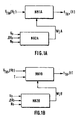
- the control system 100 essentially comprises first and second predictive and adaptive calculation means couples, NN1A and NN2A, or NN1B and NN2B, to supply, from the initial voltage values Vo, ⁇ Vo, No, and a critical threshold V TH , and possibly from the instantaneous value Tt measured in a discharge phase, the predictive indication of an instant called critical instant t TH or, in the same discharge phase, the battery voltage will reach this critical threshold V TH , and more specifically, a predictive indication of the time lapse ⁇ t TH remaining to run before this critical discharge voltage threshold V TH is reached, this threshold being predetermined so that, before the battery voltage reaches this threshold V TH , the host system 130 has a precisely known operating energy, and located within a certain range where this energy is correctly adapted to the operation of the host device 13 0.
- the first and second predictive calculation means and of the control system 100 are respectively made up by a first neural network referenced NN1A, and a second neural network referenced NN2A connected in series with the first neural network NN1A.
- a discharge phase starting at an instant to in a charge-discharge cycle, is first considered; and a predetermined critical discharge voltage threshold V TH is fixed.
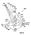
- Synaptic coefficients or weights of this first neural network NN1A are 13 in number and are referenced WjA where "j" is an index from 1 to 13. They are calculated and supplied automatically at each current instant t of this phase of discharge, by the second neural network NN2A.
- Each of the neural networks NN1A and NN2A must be organized (or arranged) to carry out these calculations and provide these exits. To this end, each of them is subject to a procedure and a test procedure called phases during which their synaptic coefficients are determined and, in some cases, fixed.
- the task of the first NN1A neural network is to learn models of discharge curves. This learning makes it possible to construct a relationship between the battery discharge voltage denoted Vt, and the current instant t when the battery reaches this voltage Vt.
- the NN1A neural network was built to generate a nonlinear function Fw.
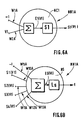
- each hidden neuron noted NC1 to NC4
- NC1 to NC4 are those of a formal neuron "standard", and are illustrated in FIG.6A, which shows the cell hidden NC1, as an example.
- Each hidden neuron given NCi receives on the one hand in input the voltage Vt with a weight, or synaptic coefficient input, which is one of the 13 weights referenced WjA, and receives other share a threshold whose value is the constant "-1", assigned a other of the 13 weights referenced WjA.
- the index "i" is the index 1 to 4 of the hidden neural cell NC1 to NC4 concerned.
- Each neuron hidden NCi realizes a weighted sum, noted ⁇ of the affected inputs of one of the weights WjA, and calculates an intermediate output Ei (Vt).
- the activation function Si is preferably a sigmoid function "tanh" equal to the hyperbolic tangent function, which is very well suited to the shape of the discharge curves to build, as will be shown later.
- the 4 neuronal cells NC1 to NC4 therefore show in the example described, a nonlinear function tanh.
- the structure of the single NS output neuron is illustrated in FIG. 6B. He realizes a weighted sum, noted ⁇ , of outputs Si (Vt) of all hidden neurons NCi, using synaptic coefficients WjA, sum plus the value a threshold "-1" coming from the hidden cell NC0, this value of threshold being introduced into the NS output neuron through one synaptic coefficients WjA.
- This output neuron therefore first performs the sum weighted ⁇ which gives an intermediate output Es (Vt).
- the Ls activation function of this output neuron is chosen linear.
- the output of the output neuron is the function Fw that we are trying to generate.
- the notations of the weights of each hidden neuron NCi are indicated in FIG. 2A, as well as the notations of the input weights of the NS output neuron. All of these weights noted W1A to W13A is formed by the set of 13 weights WjA transmitted by the second NN2A neural network.
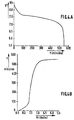
- a conventional curve discharge of a cadmium-nickel battery taken by way of example gives the voltage Vt in volts as a function of time t in minutes.
- This curve shows a steep slope in the first period of battery operation, for example the first 100 minutes, then a slight slope between 100 and 500 minutes of use, and finally again a steep slope beyond 500 minutes.
- this discharge curve is given quite done as an example.
- FIG.4B shows an example of a discharge curve which of interest in this description.
- This curve shows the time t as a function of the battery voltage Vt.
- This curve of FIG. 4B is drawn simply by carrying the values which were on the abscissa on FIG. 4A, on the ordinate on the FIG.4B; and by carrying the values which were on the ordinate on the FIG.4A on the abscissa in FIG.4B.
- this discharge curve has a shape approaching the shape of a curve tanh. This is why the functions of the type of sigmoid are preferred for performing activation functions in neurons of the hidden layer.
- FIG.4B now provides a discharge curve giving the time t in minutes as a function of the voltage Vt in volts which shows almost flat end parts and a part intermediate with a steep slope. This is why the modeling of the intermediate part of the discharge curves of relation (1a) is carried out by the first two cells neuronal NC1, NC2 of the hidden layer, whose functions activation respectively have a steep slope; while modeling of the extreme parts of these curves is carried out by the following hidden neuronal cells NC3, NC4, which show a lower slope activation function.
- cells hidden NC1, NC2 can be for example 7.0, and the slopes of activation functions of the following hidden cells NC2, NC4 can be for example 2.0.
- discharge time t curves as a function of the voltage V (t) of discharge are recorded for example every minute for a large number N of discharge cycles, and for a large number of 110 batteries of the same type, for example batteries nickel-cadmium.
- 20 x 140 2800 discharge curves are recorded, so that each curve provides 1600 points.
- each curve is taught to a different NN1A network. So in the learning phase, 2800 networks are initialized, that is to say 1 network per curve. In each curve, for example the half of the points, i.e. 800 points, is used to learning the corresponding neuron network and the other half of the points, i.e. 800 other points, is used to test said neural network.
- the 13 WjA weights of each of the 2800 NN1A neural networks are stored in a memory area long live RAM.
- the RAM is referenced 170b.
- the task of the second neural network NN2A is to learn a relation between parameters depending on the discharge voltage of the battery. So the second neural network NN2A receives No the number of previous cycles, Vo the first recorded voltage of a given discharge curve, and ⁇ Vo the slope at the origin of this discharge curve, and must be able to calculate, from these measurements, the 13 weights WjA necessary for the operation of the first neural network NN1B.
- the inputs constituted by the initial values Vo and ⁇ Vo were specifically chosen because that it appeared that these were the values most sensitive to battery characteristics.
- the third input consisting of the initial number of cycles No, was also specifically chosen because it makes it possible to take into account an effect of aging of the battery, since the more a battery has undergone charge-discharge cycles, the less it it has life time left, that is to say the less the effect of the recharge is effective and the faster the discharge time.
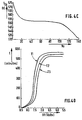
- This aging effect is illustrated in FIG. 4C, which shows the average discharge time t TH to reach the critical threshold V TH from the initial instant to, as a function of the initial number of cycles No.
- Synaptic coefficients or weights, referenced WN2A of this second neural network are fixed during its phase and are stored in the ROM area ROM 170a, shown in FIG.5B.
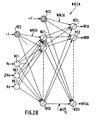
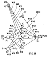
- the output cells, noted NS1 to NS13 of the second neural network NN2A have a function non-linear activation, preferably tanh.
- this second neural network NN2A has hidden cells whose slope of the sigmoid activation function is different from cell to cell the other. This embodiment allows not to use a number important hidden cell.
- the second neural network is trained in using 1400 vectors of 13 weight values generated by learning the first neuron network using 2800 recorded curves, and the other 1400 generated vectors are used for testing.
- test procedure is carried out in the manner following: for the 1400 vectors which do not belong to the batch the corresponding values Vo, ⁇ Vo and No are applied to the inputs of the second neural network. This one computes an output vector of 13 weight values as it was trained to do it.
- This first neural network NN1A then calculates the automatically adapted predictive value of discharge time t TH which is compared with that of the test curve.
- the control system 100 has two operating modes called initialization mode and commonly used mode.
- the two values Vo and ⁇ Vo are supplied to the input of the second neural network NN2A which then calculates the vector of 13 weight values WjA to be applied to the first neural network NN1A.
- the current usage mode is implemented during the discharge. In this commonly used mode, the voltage Vt does not need to be measured.
- This time difference calculation can be done by the first neural network NN1A, or it can be done by an individual calculation area, or it can be done by the calculation means 160 preferably consisting of a microprocessor shown in FIGS. 5A and 5B.
- the control system 100 comprises a first network of neurons referenced NN1B, and a second neural network referenced NN2B connected in series with the first neural network NN1B.
- a discharge phase starting at an instant to, in a charge-discharge cycle, is first considered; and a predetermined critical discharge voltage threshold V TH is fixed.
- the first neural network NN1A is coupled with time measurement means 150a, which provides a measurement of each current instant t, and is coupled with computing means 160 which provides by difference between l 'current instant t and the calculated value of instant t TH ; a value ⁇ t TH of the time remaining before the predetermined critical discharge voltage threshold V TH is reached, in normal operation.
- Synaptic coefficients or weights, referenced WjB, of this first NN1B neural network are calculated and supplied to the current instant t of this discharge phase, as in the first embodiment already described, by the second network of NN2B neurons.
- Each of the neural networks NN1B and NN2B must be organized (or arranged) to carry out these calculations and provide these exits. To this end, each of them is subject to a procedure and a test procedure called phases during which their synaptic coefficients are determined and, in some cases, fixed.
- the task of the first neural network NN1B is to learn models of discharge curves. This learning makes it possible to construct a relationship between the battery voltage Vt, the temperature Tt, and the instant t when the battery reaches this discharge voltage denoted Vt, for this temperature Tt.
- each neural networks NN1B and NN2B are implemented in the same way that the learning and testing phases of neurons NN1A and NN2A of the first exemplary embodiment of the system control, except that the discharge curves are learned for several different temperatures.
- the weights of this first neural network are referenced WjB and are 17 in number.
- the index "j" represents the numbers 1 to 17.
- Each hidden neuron given NCi receives on the one hand in input the voltage Vt with one of the weights referenced WjB, the temperature with another one of the weights WjB, and on the other hand receives a threshold having as value the constant "-1", affected by another of weight WjB.
- the index "i" is the index 1 to 4 of the neuronal cell hidden NC1 to NC4 concerned.
- Each hidden neuron NCi performs a weighted sum, and calculates an intermediate output as described in relationship with the first embodiment of the control system 100.
- Each hidden neuron NC1 to NC4 transfers this sum weighted, through an activation function Si, and it calculates a output noted Si (Vt, Tt) as already described, taking into account now of the temperature.
- the activation function Si is still, in this second example, a sigmoid function "tanh" representing the function hyperbolic tangent, which is very well adapted to the shape of discharge curves to be constructed. So in the hidden layer, the 4 neuronal cells CN1 to CN4 show a non-linear function tanh.
- the structure of the single NS output neuron achieves a weighted sum of the outputs Si (Vt, Tt) of all the hidden neurons NCi, using synaptic coefficients WjB, sum at which is added the value of a threshold "-1" coming from the hidden cell NC0, this threshold value being introduced into the neuron of NS output through one of the WjB synaptic coefficients.
- the output neuron NS transfers this weighted sum to through an activation function noted Ls, and it calculates an output noted Fw (Vt, Tt).
- the Ls activation function of this output neuron is linear.
- the output of the NS output neuron is therefore the value Fw that we are trying to generate.
- FIG.4D An example of discharge curves which interests the this description is shown in FIG.4D.
- This curve shows the time t as a function of the battery voltage Vt, for different values T1, T2, T3, of the temperature T considered as a parameter.
- These discharge curves each have a shape approaching the shape of a tanh curve. Therefore, the functions of the sigmoid type are preferred for performing the functions activation in neurons of the hidden layer.
- Example I the modeling of the part intermediate discharge curves is performed by the two first neural cells of the hidden layer NC1, NC2, whose activation functions have a steep slope respectively, while the modeling of the extreme parts of these curves is carried out by the following hidden neuronal cells NC3, NC4, which show a lower slope activation function.
- the task of the second neural network NN2B is to learn a relation between parameters depending on the discharge voltage of the battery.
- the second neural network NN2B receives No the number of previous cycles called the initial number of charge-, discharge cycles, Vo the first recorded voltage of a given discharge curve, and ⁇ Vo the slope at the origin of this curve of discharge, and must be able to calculate, from these measurements, the 17 weights WjB necessary for the functioning of the first neural network NN1B.
- the first neural network can independently give an output, either an indication of the instant t TH where the critical value V TH of the voltage threshold is reached, either an indication, or both indications.
- This difference can be calculated outside the first neural network by the calculation means denoted 160 in FIGS. 5A and 5B.
- This indication of the instant t TH can then be made available to the user of the host system by appropriate display means 140 giving the time.
- the battery is subjected to a charging phase which is completed when the voltage of battery reaches the initial value Vo, which is for example 9V.
- the display means can display an indication that the battery recharge is complete.
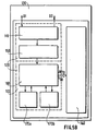
- the control system 100 is implemented by a microprocessor 160 to perform calculations, and memory areas 170a, 170b to store the data. These memory areas are accessible by microprocessor 160 and include a memory area storage device 170a for storing the structure data of first and second neural networks NN1A, NN2A, NN1B, NN2B, the fixed parameters and the weights WN2A, WN2B of the second network of neurons, and a RAM 170b RAM area to save or provide variable measures and weight vectors as appropriate WjA, WjB of the first and second neural networks.
- the microprocessor 160 performs the necessary calculations for operation of the control system.
- the control system 100 is coupled to display means 140 to provide the user with an indication of the time t TH or else of the time lapse ⁇ t TH remaining to run from a current instant t of use until the moment when the battery reaches this predetermined critical voltage threshold Vt TH , or both indications.
- the display means 140 can also display the time, that is to say an indication of the current instant t; these display means can also display an indication, in a battery recharging phase, that this recharging phase is finished, when the battery has reached the initial voltage Vo.
- control system 100 makes part of a host device 130 which comprises connection means D1, D2 for the 110 rechargeable battery.
- the rechargeable battery 110 is coupled to the control system 100 to form the battery intelligent 120.
- the host device 130 furthermore houses the means measurement 150, for example a multimeter, microprocessor 160, the memory zones 170a, 170b accessible by the microprocessor 160, and the display means 140.
- a device can be a screen with written indications, or with drawn indications, or a panel formed by diodes.
- 5B 130 Host device D1, D2 Host Device and Battery Connection 110 Rechargeable battery 150 Means of measuring time, temperature and voltages 160 Microprocessor to perform calculations 170a Read only memory area (ROM) 170b RAM area 100 Battery control system 120 Smart battery 140 Means of displaying the current instant and calculated times, and possibly end of charge.
Landscapes
- Physics & Mathematics (AREA)
- Engineering & Computer Science (AREA)
- General Physics & Mathematics (AREA)
- Power Engineering (AREA)
- Theoretical Computer Science (AREA)
- Data Mining & Analysis (AREA)
- General Health & Medical Sciences (AREA)
- Biomedical Technology (AREA)
- Biophysics (AREA)
- Computational Linguistics (AREA)
- Life Sciences & Earth Sciences (AREA)
- Evolutionary Computation (AREA)
- Artificial Intelligence (AREA)
- Molecular Biology (AREA)
- Computing Systems (AREA)
- General Engineering & Computer Science (AREA)
- Mathematical Physics (AREA)
- Software Systems (AREA)
- Health & Medical Sciences (AREA)
- Secondary Cells (AREA)
- Charge And Discharge Circuits For Batteries Or The Like (AREA)
Applications Claiming Priority (2)
| Application Number | Priority Date | Filing Date | Title |
|---|---|---|---|
| FR9512863 | 1995-10-31 | ||
| FR9512863A FR2740554A1 (fr) | 1995-10-31 | 1995-10-31 | Systeme de controle de la phase de decharge des cycles de charge-decharge d'une batterie rechargeable, et dispositif hote muni d'une batterie intelligente |
Publications (3)
| Publication Number | Publication Date |
|---|---|
| EP0772055A2 EP0772055A2 (fr) | 1997-05-07 |
| EP0772055A3 EP0772055A3 (fr) | 1997-05-14 |
| EP0772055B1 true EP0772055B1 (fr) | 2004-08-25 |
Family
ID=9484105
Family Applications (1)
| Application Number | Title | Priority Date | Filing Date |
|---|---|---|---|
| EP96202927A Expired - Lifetime EP0772055B1 (fr) | 1995-10-31 | 1996-10-21 | Système de contrôle de la phase de décharge des cycles de charge-décharge d'une batterie rechargeable, et dispositif hôte muni d'une batterie intelligente |
Country Status (6)
| Country | Link |
|---|---|
| US (1) | US5936385A (enExample) |
| EP (1) | EP0772055B1 (enExample) |
| JP (1) | JP3887048B2 (enExample) |
| KR (1) | KR100453750B1 (enExample) |
| DE (1) | DE69633216T2 (enExample) |
| FR (1) | FR2740554A1 (enExample) |
Cited By (1)
| Publication number | Priority date | Publication date | Assignee | Title |
|---|---|---|---|---|
| KR100813925B1 (ko) | 2005-04-20 | 2008-03-18 | 가부시키가이샤 덴소 | 뉴럴 네트워크 연산에 기초하여 2차 전지의 충전 상태를검출하기 위한 방법 및 장치 |
Families Citing this family (49)
| Publication number | Priority date | Publication date | Assignee | Title |
|---|---|---|---|---|
| WO1998040951A1 (en) | 1997-03-12 | 1998-09-17 | Us Nanocorp. | Method for determining state-of-health using an intelligent system |
| FR2801982B1 (fr) * | 1999-12-06 | 2002-02-01 | Alain Leroy | Dispositif de controle d'une batterie d'accumulateurs et son procede associe |
| DE19959019A1 (de) * | 1999-12-08 | 2001-06-13 | Bosch Gmbh Robert | Verfahren zur Zustandserkennung eines Energiespeichers |
| US6928371B1 (en) * | 2000-02-08 | 2005-08-09 | Paul T. Roshau | Monitoring system of VRLA battery capacitance |
| DE10012964A1 (de) * | 2000-03-16 | 2001-10-04 | Implex Hear Tech Ag | Vorrichtung und Verfahren zum Betreiben eines wiederaufladbaren Speichers für elektrische Energie |
| DE10104981A1 (de) * | 2001-02-03 | 2002-08-08 | Varta Geraetebatterie Gmbh | Verfahren zur Überwachung der Betriebssicherheit von wiederaufladbaren Li-Zellen |
| US7205746B2 (en) * | 2001-04-06 | 2007-04-17 | Microchip Technology Inc. | Battery cover assembly having integrated battery condition monitoring |
| US6628102B2 (en) * | 2001-04-06 | 2003-09-30 | Microchip Technology Inc. | Current measuring terminal assembly for a battery |
| KR100426518B1 (ko) * | 2001-12-14 | 2004-04-08 | 에스케이텔레텍주식회사 | 이동통신 단말기 배터리 충전방법 |
| GB2386709B (en) * | 2002-03-18 | 2004-03-17 | Ching Chuen Chan | Battery residual capacity estimation for electric vehicles |
| US7321220B2 (en) * | 2003-11-20 | 2008-01-22 | Lg Chem, Ltd. | Method for calculating power capability of battery packs using advanced cell model predictive techniques |
| WO2005059579A1 (en) * | 2003-12-18 | 2005-06-30 | Lg Chem, Ltd. | Apparatus and method for estimating state of charge of battery using neural network |
| US7518341B2 (en) | 2004-12-23 | 2009-04-14 | Dell Product L.P. | Method for verifying smart battery failures by measuring input charging voltage and associated systems |
| KR100880717B1 (ko) * | 2005-02-14 | 2009-02-02 | 가부시키가이샤 덴소 | 뉴럴네트워크연산에 기초한 2차전지의 충전상태를 검출하기위한 방법 및 장치 |
| KR101762083B1 (ko) | 2005-05-12 | 2017-07-26 | 가부시키가이샤 니콘 | 투영 광학계, 노광 장치 및 노광 방법 |
| US7970560B2 (en) * | 2005-10-11 | 2011-06-28 | Phoenix Broadband Technologies, Llc | Method and apparatus for measuring and monitoring a power source |
| US7723957B2 (en) * | 2005-11-30 | 2010-05-25 | Lg Chem, Ltd. | System, method, and article of manufacture for determining an estimated battery parameter vector |
| GB2444511B (en) * | 2006-12-06 | 2008-10-22 | Iti Scotland Ltd | Battery Management System |
| JP2009049005A (ja) * | 2007-07-26 | 2009-03-05 | Panasonic Corp | 電池の内部短絡検知装置および方法、電池パック並びに電子機器システム |
| KR100936892B1 (ko) * | 2007-09-13 | 2010-01-14 | 주식회사 엘지화학 | 배터리의 장기 특성 예측 시스템 및 방법 |
| US8379187B2 (en) | 2007-10-24 | 2013-02-19 | Nikon Corporation | Optical unit, illumination optical apparatus, exposure apparatus, and device manufacturing method |
| US9116346B2 (en) | 2007-11-06 | 2015-08-25 | Nikon Corporation | Illumination apparatus, illumination method, exposure apparatus, and device manufacturing method |
| US7994755B2 (en) | 2008-01-30 | 2011-08-09 | Lg Chem, Ltd. | System, method, and article of manufacture for determining an estimated battery cell module state |
| US8032316B2 (en) | 2008-04-16 | 2011-10-04 | Phoenix Broadband Technologies, Llc | Measuring and monitoring a power source |
| CN101728585B (zh) * | 2008-10-31 | 2012-08-15 | 纬创资通股份有限公司 | 便携式装置延长充电电池使用寿命的电池学习方法及装置 |
| US11218003B2 (en) * | 2009-09-22 | 2022-01-04 | Phoenix Broadband Technologies, Llc | Method and apparatus for intelligent battery charge equalization and monitoring |
| US8330425B2 (en) | 2009-10-19 | 2012-12-11 | Verizon Patent And Licensing Inc. | System for and method of detecting a non-functional battery back-up unit (BBU) of an optical network terminal |
| US8341449B2 (en) | 2010-04-16 | 2012-12-25 | Lg Chem, Ltd. | Battery management system and method for transferring data within the battery management system |
| WO2011143156A2 (en) * | 2010-05-13 | 2011-11-17 | Massachusetts Institute Of Technology | Battery charger circuit and control schemes |
| US8449998B2 (en) | 2011-04-25 | 2013-05-28 | Lg Chem, Ltd. | Battery system and method for increasing an operational life of a battery cell |
| US8993136B2 (en) | 2011-06-30 | 2015-03-31 | Lg Chem, Ltd. | Heating system for a battery module and method of heating the battery module |
| US8859119B2 (en) | 2011-06-30 | 2014-10-14 | Lg Chem, Ltd. | Heating system for a battery module and method of heating the battery module |
| US8974929B2 (en) | 2011-06-30 | 2015-03-10 | Lg Chem, Ltd. | Heating system for a battery module and method of heating the battery module |
| US8974928B2 (en) | 2011-06-30 | 2015-03-10 | Lg Chem, Ltd. | Heating system for a battery module and method of heating the battery module |
| US9020649B2 (en) * | 2011-07-18 | 2015-04-28 | Nec Laboratories America, Inc. | Method for real-time power management of a grid-tied microgrid to extend storage lifetime and reduce cost of energy |
| US8816644B2 (en) | 2011-08-30 | 2014-08-26 | Perumala Corporation | Interrupting the charging status of a rechargeable battery |
| US8598850B2 (en) | 2011-08-30 | 2013-12-03 | Perumala Corporation | Devices and methods for optimizing rechargeable battery life |
| USD720287S1 (en) | 2011-08-30 | 2014-12-30 | Perumala Corporation | Charge interrupting device |
| US9442165B2 (en) * | 2012-07-07 | 2016-09-13 | Nec Corporation | Method for estimating battery life in presence of partial charge and discharge cycles |
| DE102013201529A1 (de) * | 2013-01-30 | 2014-07-31 | Ford Global Technologies, Llc | Verfahren und Vorrichtung zur Überwachung mindestens einer Traktionsbatterie eines Kraftfahrzeugs |
| USD757649S1 (en) | 2013-12-19 | 2016-05-31 | Perumala Corporation | Adapter |
| US10295608B2 (en) | 2014-07-18 | 2019-05-21 | Phoenix Broadband Technologies, Llc | Non-intrusive correlating battery monitoring system and method |
| WO2017015396A1 (en) * | 2015-07-20 | 2017-01-26 | University Of Washington | Battery models, systems, and methods using robust fail-safe iteration free approach for solving differential algebraic equations |
| EP3537730A1 (en) * | 2018-03-09 | 2019-09-11 | Oticon A/s | A method for updating a discharge battery profile |
| JP2019158831A (ja) * | 2018-03-16 | 2019-09-19 | 株式会社Gsユアサ | 検査方法、検査装置及び学習モデル |
| DE102020105246A1 (de) | 2020-02-27 | 2021-09-02 | Wacker Neuson Produktion GmbH & Co. KG | Akkumulator mit Geräteerkennungsfunktion und Verfahren zur Geräteerkennung |
| CN111257762B (zh) * | 2020-03-10 | 2022-06-14 | 信义电源(苏州)有限公司 | 提前预判电池循环失效的方法 |
| KR102790387B1 (ko) * | 2020-11-26 | 2025-04-01 | 주식회사 엘지화학 | 배터리 관리 장치 및 방법 |
| FR3119895A1 (fr) * | 2021-02-18 | 2022-08-19 | Psa Automobiles Sa | Estimateur d’État de charge d’un vÉhicule utilisant l’intelligence artificielle |
Family Cites Families (8)
| Publication number | Priority date | Publication date | Assignee | Title |
|---|---|---|---|---|
| DE59002764D1 (de) * | 1989-05-12 | 1993-10-21 | Fraunhofer Ges Forschung | Verfahren zur bestimmung von physikalischen grössen von wiederaufladbaren elektrischen energiespeichern. |
| US4952862A (en) * | 1989-09-29 | 1990-08-28 | At&T Bell Laboratories | Apparatus and method for adaptively predicting battery discharge reserve time |
| IT1244942B (it) * | 1991-03-18 | 1994-09-13 | Enea | Metodo e dispositivo per la stima dello stato di carica di accumulatori elettrochimici e per il controllo degli impianti che li utilizzano |
| JP3371146B2 (ja) * | 1992-08-18 | 2003-01-27 | ソニー株式会社 | バッテリとバッテリ課金方法 |
| US5714866A (en) * | 1994-09-08 | 1998-02-03 | National Semiconductor Corporation | Method and apparatus for fast battery charging using neural network fuzzy logic based control |
| US5633573A (en) * | 1994-11-10 | 1997-05-27 | Duracell, Inc. | Battery pack having a processor controlled battery operating system |
| US5565759A (en) * | 1994-12-15 | 1996-10-15 | Intel Corporation | Smart battery providing battery life and recharge time prediction |
| US5615129A (en) * | 1995-02-21 | 1997-03-25 | General Signal Power Systems, Inc. | Method and apparatus for adaptive and corrective determination of battery run-time in uninterruptible power systems |
-
1995
- 1995-10-31 FR FR9512863A patent/FR2740554A1/fr not_active Withdrawn
-
1996
- 1996-10-21 DE DE69633216T patent/DE69633216T2/de not_active Expired - Lifetime
- 1996-10-21 EP EP96202927A patent/EP0772055B1/fr not_active Expired - Lifetime
- 1996-10-30 US US08/739,770 patent/US5936385A/en not_active Expired - Fee Related
- 1996-10-31 JP JP29016696A patent/JP3887048B2/ja not_active Expired - Fee Related
- 1996-10-31 KR KR1019960052191A patent/KR100453750B1/ko not_active Expired - Fee Related
Cited By (1)
| Publication number | Priority date | Publication date | Assignee | Title |
|---|---|---|---|---|
| KR100813925B1 (ko) | 2005-04-20 | 2008-03-18 | 가부시키가이샤 덴소 | 뉴럴 네트워크 연산에 기초하여 2차 전지의 충전 상태를검출하기 위한 방법 및 장치 |
Also Published As
| Publication number | Publication date |
|---|---|
| DE69633216T2 (de) | 2005-09-22 |
| JPH09215208A (ja) | 1997-08-15 |
| JP3887048B2 (ja) | 2007-02-28 |
| FR2740554A1 (fr) | 1997-04-30 |
| EP0772055A3 (fr) | 1997-05-14 |
| KR970024432A (ko) | 1997-05-30 |
| DE69633216D1 (de) | 2004-09-30 |
| US5936385A (en) | 1999-08-10 |
| EP0772055A2 (fr) | 1997-05-07 |
| KR100453750B1 (ko) | 2005-04-06 |
Similar Documents
| Publication | Publication Date | Title |
|---|---|---|
| EP0772055B1 (fr) | Système de contrôle de la phase de décharge des cycles de charge-décharge d'une batterie rechargeable, et dispositif hôte muni d'une batterie intelligente | |
| EP0772056B1 (fr) | Système de contrôle des cycles de charge-décharge d'une batterie rechargeable, et dispositif hôte muni d'une batterie intelligente | |
| EP2410346B1 (fr) | Procédé de détermination d'un paramètre d'au moins un accumulateur d'une batterie | |
| EP3443370B1 (fr) | Procede de determination de la valeur de parametres relatifs a l'etat d'un accumulateur d'une batterie, batterie et systeme de gestion electronique d'une batterie | |
| EP3811487B1 (fr) | Systeme électrique à cellules commutées et procédé de commande d'un tel système | |
| FR2841385A1 (fr) | Dispositif de calcul du degre de deterioration et procede de calcul du degre de deterioration d'une batterie | |
| FR2943794A1 (fr) | Procede de determination de l'etat de sante d'une batterie | |
| FR2884928A1 (fr) | Procede et dispositif de detection de l'etat charge d'une batterie d'accumulateurs fondes sur un calcul de reseau neuronal | |
| FR2694637A1 (fr) | Procédé de détermination du temps d'autonomie d'une batterie. | |
| CA3114194A1 (fr) | Procede et dispositif de mesure en temps reel et in situ des donnees thermodynamiques d'une batterie (enthalpie et entropie) | |
| FR2971854A1 (fr) | Dispositif embarque d'estimation du vieillissement d'une batterie d'alimentation de vehicule automobile et procede correspondant. | |
| EP0752591B1 (fr) | Mesure numérique relative de haute précision d'une tension | |
| EP3974853A1 (fr) | Prédiction de l'état de santé futur des cellules d'une batterie électrique | |
| EP2449392A1 (fr) | Procede de calibration d'un accumulateur electrochimique | |
| WO2022229516A1 (fr) | Procede de prediction par intelligence artificielle de la duree de vie restante d´ un element electrochimique de batterie et dispositifs associes | |
| EP3559688A1 (fr) | Caractérisation perfectionnée d'un dispositif électrochimique en opération pour un pronostic de fonctionnement futur du dispositif | |
| EP4390424B1 (fr) | Procédé de détermination de l'état de santé (soh) d'une cellule de batterie li-ion | |
| EP3999863B1 (fr) | Estimation du soc d'un elément electrochimique | |
| FR3135328A1 (fr) | Procédé d’estimation de l’état de charge d’un élément électrochimique et dispositifs associés | |
| FR3074301B1 (fr) | Procede de surveillance et de gestion d'un parc de batteries | |
| EP4206705A1 (fr) | Détermination du rendement d'un accumulateur électrique par conversion | |
| FR3162863A1 (fr) | Procédé d’estimation d’un paramètre représentatif de l’état d’au moins un élément électrochimique d’une batterie, procédé et dispositifs associés | |
| FR2871576A1 (fr) | Dispositif et procede d'estimation de pertes par effet joule et d'etat de charge d'une batterie, et support d'enregistrement pour leur mise en oeuvre |
Legal Events
| Date | Code | Title | Description |
|---|---|---|---|
| PUAI | Public reference made under article 153(3) epc to a published international application that has entered the european phase |
Free format text: ORIGINAL CODE: 0009012 |
|
| PUAL | Search report despatched |
Free format text: ORIGINAL CODE: 0009013 |
|
| AK | Designated contracting states |
Kind code of ref document: A2 Designated state(s): DE ES FR GB IT |
|
| AK | Designated contracting states |
Kind code of ref document: A3 Designated state(s): DE ES FR GB IT |
|
| 17P | Request for examination filed |
Effective date: 19971114 |
|
| RAP1 | Party data changed (applicant data changed or rights of an application transferred) |
Owner name: KONINKLIJKE PHILIPS ELECTRONICS N.V. |
|
| 17Q | First examination report despatched |
Effective date: 20030502 |
|
| GRAP | Despatch of communication of intention to grant a patent |
Free format text: ORIGINAL CODE: EPIDOSNIGR1 |
|
| GRAS | Grant fee paid |
Free format text: ORIGINAL CODE: EPIDOSNIGR3 |
|
| GRAA | (expected) grant |
Free format text: ORIGINAL CODE: 0009210 |
|
| AK | Designated contracting states |
Kind code of ref document: B1 Designated state(s): DE ES FR GB IT |
|
| PG25 | Lapsed in a contracting state [announced via postgrant information from national office to epo] |
Ref country code: IT Free format text: LAPSE BECAUSE OF FAILURE TO SUBMIT A TRANSLATION OF THE DESCRIPTION OR TO PAY THE FEE WITHIN THE PRESCRIBED TIME-LIMIT;WARNING: LAPSES OF ITALIAN PATENTS WITH EFFECTIVE DATE BEFORE 2007 MAY HAVE OCCURRED AT ANY TIME BEFORE 2007. THE CORRECT EFFECTIVE DATE MAY BE DIFFERENT FROM THE ONE RECORDED. Effective date: 20040825 |
|
| REG | Reference to a national code |
Ref country code: GB Ref legal event code: FG4D Free format text: NOT ENGLISH |
|
| REF | Corresponds to: |
Ref document number: 69633216 Country of ref document: DE Date of ref document: 20040930 Kind code of ref document: P |
|
| PG25 | Lapsed in a contracting state [announced via postgrant information from national office to epo] |
Ref country code: ES Free format text: LAPSE BECAUSE OF FAILURE TO SUBMIT A TRANSLATION OF THE DESCRIPTION OR TO PAY THE FEE WITHIN THE PRESCRIBED TIME-LIMIT Effective date: 20041206 |
|
| GBT | Gb: translation of ep patent filed (gb section 77(6)(a)/1977) |
Effective date: 20041201 |
|
| REG | Reference to a national code |
Ref country code: GB Ref legal event code: 746 Effective date: 20041221 |
|
| PLBE | No opposition filed within time limit |
Free format text: ORIGINAL CODE: 0009261 |
|
| STAA | Information on the status of an ep patent application or granted ep patent |
Free format text: STATUS: NO OPPOSITION FILED WITHIN TIME LIMIT |
|
| 26N | No opposition filed |
Effective date: 20050526 |
|
| PGFP | Annual fee paid to national office [announced via postgrant information from national office to epo] |
Ref country code: GB Payment date: 20091030 Year of fee payment: 14 Ref country code: FR Payment date: 20091116 Year of fee payment: 14 |
|
| PGFP | Annual fee paid to national office [announced via postgrant information from national office to epo] |
Ref country code: DE Payment date: 20091229 Year of fee payment: 14 |
|
| GBPC | Gb: european patent ceased through non-payment of renewal fee |
Effective date: 20101021 |
|
| PG25 | Lapsed in a contracting state [announced via postgrant information from national office to epo] |
Ref country code: FR Free format text: LAPSE BECAUSE OF NON-PAYMENT OF DUE FEES Effective date: 20101102 |
|
| REG | Reference to a national code |
Ref country code: FR Ref legal event code: ST Effective date: 20110630 |
|
| PG25 | Lapsed in a contracting state [announced via postgrant information from national office to epo] |
Ref country code: GB Free format text: LAPSE BECAUSE OF NON-PAYMENT OF DUE FEES Effective date: 20101021 |
|
| REG | Reference to a national code |
Ref country code: DE Ref legal event code: R119 Ref document number: 69633216 Country of ref document: DE Effective date: 20110502 |
|
| PG25 | Lapsed in a contracting state [announced via postgrant information from national office to epo] |
Ref country code: DE Free format text: LAPSE BECAUSE OF NON-PAYMENT OF DUE FEES Effective date: 20110502 |