EP0772054A2 - Method and device for testing an electric conductor arrangement - Google Patents
Method and device for testing an electric conductor arrangement Download PDFInfo
- Publication number
- EP0772054A2 EP0772054A2 EP96117642A EP96117642A EP0772054A2 EP 0772054 A2 EP0772054 A2 EP 0772054A2 EP 96117642 A EP96117642 A EP 96117642A EP 96117642 A EP96117642 A EP 96117642A EP 0772054 A2 EP0772054 A2 EP 0772054A2
- Authority
- EP
- European Patent Office
- Prior art keywords
- networks
- conductance
- measurement
- network
- values
- Prior art date
- Legal status (The legal status is an assumption and is not a legal conclusion. Google has not performed a legal analysis and makes no representation as to the accuracy of the status listed.)
- Granted
Links
Images

Classifications
-
- G—PHYSICS
- G01—MEASURING; TESTING
- G01R—MEASURING ELECTRIC VARIABLES; MEASURING MAGNETIC VARIABLES
- G01R31/00—Arrangements for testing electric properties; Arrangements for locating electric faults; Arrangements for electrical testing characterised by what is being tested not provided for elsewhere
- G01R31/28—Testing of electronic circuits, e.g. by signal tracer
- G01R31/2801—Testing of printed circuits, backplanes, motherboards, hybrid circuits or carriers for multichip packages [MCP]
- G01R31/2805—Bare printed circuit boards
-
- G—PHYSICS
- G01—MEASURING; TESTING
- G01R—MEASURING ELECTRIC VARIABLES; MEASURING MAGNETIC VARIABLES
- G01R31/00—Arrangements for testing electric properties; Arrangements for locating electric faults; Arrangements for electrical testing characterised by what is being tested not provided for elsewhere
- G01R31/28—Testing of electronic circuits, e.g. by signal tracer
- G01R31/302—Contactless testing
- G01R31/312—Contactless testing by capacitive methods
Definitions
- the invention relates to a method and a device for testing an electrical conductor arrangement.
- Such conductor arrangements are generally embedded in so-called printed circuit boards and can have a large number of spatially closely spaced interconnects or networks.
- network is used for the term “conductor track”, but this does not mean that the network must have branching points.
- DE 34 08 704 A1 discloses a device for testing an electrical conductor arrangement, in which the individual networks are measured by means of a resistance and capacitance measurement. The measured values determined are compared with predetermined reference values of an error-free conductor arrangement. Deviations of the measured values from the reference values can be used to determine both the presence of an error in the network and the type and location of the error. This measuring method has proven itself in practice because it can be carried out easily and quickly and enables reliable error detection.
- the determination of the reference values is a complex process.
- the reference values can be determined by corresponding resistance and capacitance measurements on a faultless conductor arrangement, a so-called “golden board".
- the production of a "golden board” is complex and expensive and cannot be realized with modern circuit boards with a high network density.
- EP 0 508 062 B1 describes a method for testing electrical conductor arrangements in which each network is measured with respect to a predetermined number of antennas.
- External elongated electrodes can be used as antennas, which are arranged on the surface of a circuit board containing the conductor arrangement. It is also possible to use certain networks of the conductor arrangement with respect to networks other than antennas, so that no additional external antennas have to be provided.
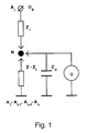
- Such a measuring arrangement with n antennas A 1 -A n and the network N to be measured is shown schematically in FIG. 1.
- a complex input voltage U 0 is applied to one of the antennas A i , and the other antennas A 1 -A i-1 and A i + 1 -A n are connected to ground.
- the complex input voltage U 0 U 0R + iU 0I is made up of a constant DC voltage component and an AC voltage component with a certain frequency 2 ⁇ composed.
- This input voltage U 0 is applied to one of the antennas, the measured value U i being tapped at the network N each time.
- the set of measured values U 1 -U n forms a data field, the values of which represent a "fingerprint" typical of the network N. This measuring method is called field measurement.
- the data fields of the individual networks usually differ. However, if the data fields of two networks are the same, this is usually due to a short circuit between these two networks. This can be checked with a conventional short-circuit test, in which the electrical resistance between these two networks is measured. These short-circuit tests only have to be carried out on networks with identical data fields, so that the measurement effort is very low compared to similar measurement methods.
- the interruption can be checked in a known manner by measuring the resistance, in which electrodes tap the resistance at the ends of the network, or by comparing the data field with a reference field.
- the invention has for its object to provide a simple and quick method for testing an electrical conductor arrangement and an apparatus for performing this method.
- the object is achieved by a method having the features of claim 1, 13, 15 and by a device having the features of claim 19.
- a first conductor arrangement is measured in a first measuring process by means of a field measurement to determine short circuits between individual networks and by means of a resistance measurement to determine interruptions in the individual networks. From the data fields determined in this way, conductance values between the individual networks and the corresponding antennas are determined and stored as reference conductance values.
- a measurement of the complex conductance between each network to be measured and a single antenna is carried out to determine short circuits, the complex actual conductance ascertained being compared with the corresponding reference conductance.
- the comparison between the conductance value and the reference conductance value can be used to determine the interruptions, high-impedance short circuits between the networks and interruptions in the networks being able to be detected by taking into account the real part of the actual conductance value.
- the method according to the invention is divided into a first measuring process for testing a first conductor arrangement and subsequent measuring processes for testing a further conductor arrangement.
- the first measurement process comprises a field measurement to determine the short circuits between networks and a resistance measurement to determine interruptions.
- a measuring arrangement for field measurement is shown schematically.
- This measuring arrangement has n antennas A 1 -A n with which a network N is measured.
- a complex input voltage U 0 is applied to one of the antennas A i
- the other antennas A 1 -A i-1 and A i + 1 -A n are connected to ground.
- FIG. 2 schematically shows a section of a conductor arrangement, four networks being used as antennas A 1 -A 4 for testing the other networks N 1 -N 4 .
- external antennas can also be used.
- This input voltage U 0 is applied to one of the antennas A i , each time a voltage U i is tapped as a measured value from the network N.
- the voltage U i is the potential of the electrical field between the antenna A, to which the input voltage U 0 is applied, and the antennas connected to ground. An electrical field is thus tapped with this voltage measurement, which is why this method is referred to as field measurement.
- the set of measured values U 1 to U n forms the data field which is characteristic of the network N.
- the data fields of the individual networks N i generally differ. If the data fields of two networks match, this is mostly due to a short circuit between these two networks. This can be checked with a conventional short-circuit test, in which the resistance between these two networks is measured. These short-circuit tests are only carried out on networks with identical or similar data fields within certain limits, so that the measurement effort is very low compared to conventional measurement methods.
- the interruption check is carried out by means of a resistance measurement, in which electrodes at the ends of the network tap the resistance.
- the combined measurement procedure with field and resistance measurement in the first measurement process makes you independent of a "golden board” or prepared reference data.
- Y I. ⁇ U iR ⁇ ( U 0 - ⁇ U iR ) - ( ⁇ U iI ) 2nd ( U 0 - ⁇ U iR ) 2nd + ( ⁇ U iI ) 2nd ⁇ ⁇ ⁇ C. p (5)
- Y R - U 0 ⁇ ⁇ U iI ( U 0 - ⁇ U iR ) 2nd + ( ⁇ U iI ) 2nd ⁇ ⁇ ⁇ C. p
- the sum symbols each represent a sum of 1 to n of a data field of a network.
- the conductance values can be determined from the data obtained with the field measurement with an accuracy of better than 1.5%, so that they are suitable as reference values for a measurement method working with a conductance comparison.
- the complex conductance values Y i between the networks and the antennas A i are therefore calculated simultaneously with the testing of a conductor arrangement.
- the guide values Y i and the capacitances C ia are stored as reference values for the subsequent measurement processes.
- a i consists of calculating from the field data. This is expedient if an antenna is used in the further measuring processes, which consists of several antennas A i which are electrically short-circuited to one another. It is also possible to save the data fields of the field measurement and to calculate the corresponding capacitances with each further measurement process, so that the arrangement of the antennas can be varied.
- the further measurement processes are carried out by measuring the conductance of the conductance values Y k between the networks N k and one of the antennas A i . These actual guide values Y k are compared with the corresponding reference values, and in the event of deviations it is examined whether there is a short circuit with another network or an interruption in the network or both.
- a short circuit can be determined similarly to the impedance comparison known from the prior art (e.g. DE 34 08 704 A1 or EP 0 438 491 B1).
- the capacitance or the impedance of the network is measured here, and if there are deviations from the reference value, a conventional resistance measurement is carried out in order to localize the short circuit.
- a disadvantage of these known methods working with an impedance comparison is that high-resistance short circuits cannot be determined from the impedance comparison. These high-resistance short-circuits can therefore only be determined with a visual inspection of the conductor arrangement, which is after one a measurement method based on an impedance comparison is absolutely necessary.
- the invention therefore preferably provides a modified comparison of the measured conductance Y i with the reference values for the determination of short circuits for the subsequent further measurement processes.
- a simple and quickly executable measurement of the conductance Y k is provided in order to determine short circuits on the networks N k , the conductance Y k being the conductance between the network N k and the respective antenna A i .
- the measurement effort is significantly reduced since no multiple scanning of a network N k by several antennas A i is necessary.
- the further measuring processes for determining short circuits between the individual networks N k are thus based on the measurement of the conductance Y k , which can be carried out simply and quickly, and high-resistance short circuits can also be determined. If a short circuit is found on a network, it is localized in a known manner with a resistance measurement.
- the values ⁇ Y and ⁇ C are empirical values that depend on the measuring device used and the type of the conductor arrangement.
- condition C 2a ⁇ C 1a can be met simply by exchanging the corresponding networks N.
- Interruptions in the networks N k can occur in the further measuring processes either by a resistance measurement known per se or by comparing the actual conductance Y k or the actual capacitance C k with the stored reference values.
- the minimum capacitance is about 1nF.
- Such capacities are generally achieved by larger track layouts with a few hundred or more test points.
- the criterion is whether there is an interruption: ⁇ * C. - Y 1 I. + ⁇ Y + ⁇ C. ⁇ ⁇ ⁇ C. 4th and Y 1 R + ⁇ Y ⁇ R TU ⁇ ⁇ 2nd ⁇ C. 2nd 8th
- the interruption can be localized using a resistance measurement known per se.
- the measured conductance Y k or the measured capacitance C ka is stored as a reference value.
- a device for carrying out the method has a plurality of electrodes 1 which can be contacted with test points 2 of the networks N k on a conductor arrangement 3 (FIGS. 2, 4).
- the electrodes 1 can preferably be used as antenna probes and as measuring probes. As antenna probes, they apply either the input voltage U 0 or ground to the networks connected to them, so that the networks connected to them act as antennas.
- the measuring probe taps off the voltage U i present at the network connected to it.
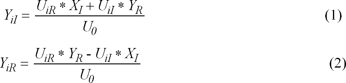
- a preferred embodiment of the measuring device is a so-called multi-finger system (FIG. 4), in which an electrode 1 is integrated into a measuring finger 4.
- a multi-finger system in which the measuring fingers can be moved independently of one another is described in EP 0 468 153 A1.
- the measuring fingers 4 can be moved parallel to the surface of the conductor arrangement 3, so that the electrodes can be contacted with certain test points 2 of the networks N k .
- Such a multi-finger system has, for example, 16 measuring fingers 4, eight being arranged above and eight below the conductor arrangement 3 in order to contact the conductor arrangement 3 from both sides.
- the measuring fingers 4 are each fastened to a carriage 6 which is controlled by a position control device 5 and which can be moved in one plane parallel to the conductor arrangement 3.
- the carriages 6 are each provided with a vertically aligned actuating cylinder 7 with which the measuring fingers 4 can be rotated about the vertical axis. Furthermore, a tilting device is integrated in the measuring fingers 4 so that the finger can be lowered onto the conductor arrangement 3 with the probe 1 arranged at its tip.
- the conductor arrangement 3 is subdivided into specific segments, with certain networks of this segment being selected as antennas for each segment.
- the networks selected as antennas are each in contact with one of the electrodes 1 during the measurement of this segment, the other electrodes 1 alternately contacting a network of the segment for receiving the measurement voltage U i .
- the network to be measured is simultaneously contacted with another electrode 1 at at least one further test point 2, so that the resistance value of the network between the two electrodes 1 can be tapped.
- the networks are checked for interruptions, whereby all test points on a network are tapped in pairs.
- the position control device 5 receives to control the movement the measuring finger 4 receives its signals from a central control unit 8.
- the central control unit 8 connects an antenna of the segment with a function generator 9, which outputs the measurement voltage U 0 , and the other antennas to ground.
- the central control unit establishes a connection of the network N k to be measured via a single electrode 1 to a first evaluation device 10 for field measurement, the voltage U i being tapped at the network N.
- Further networks N k can be scanned in the area of a segment without the electrodes 1 connected to the antennas being moved, but only the electrodes 1 for contacting the networks to be measured.
- test points 2 of the network N k are each connected in pairs to an electrode 1.
- the resistance value of this network is recorded by a second evaluation device 11 and passed on to the central control unit.
- the electrodes 1 connected to the antennas are not moved, and the other electrodes 1 are contacted with the networks to be measured.
- the first evaluation device 10 picks up the tapped voltages U i (field measurement) and forwards them to the central control unit, which determines and stores the reference guide values.
- the measuring fingers 4 are controlled so that in a segment a single electrode 1 is connected to an antenna or an antenna combination, and the other measuring fingers 4 are connected their electrodes 1 scan the test points 2 to be measured so that the capacitances C k or the imaginary part of the conductance Y kI between the antenna A and the network N k to be measured is recorded at the respective test point 2 with a third evaluation device 12.
- the resistance or the real part Y kR between the antenna A and the network N k to be measured is detected by the second evaluation device 11.
- a probe 1 is thus permanently contacted with an antenna in a further measurement process, and all test points 2 are contacted once with a probe 1 to record the conductance.
- a conductance measurement is first carried out between the antenna A and the network N k , for which purpose a probe 1 is contacted with an antenna and another probe 1 with a test point 2 of the network. To determine interruptions, all test points are contacted in pairs with two probes 1.
- the second and third evaluation devices 11, 12 for sensing resistance or capacitance are based on a current measurement.
- a multi-finger system the central control unit 8 of which is designed to carry out the method according to the invention, has to carry out a much smaller number of movements of the measuring fingers 4 when measuring the same conductor arrangements compared to known multi-finger systems, since short circuits with a single conductance measurement per network, and in the case of larger networks interruptions can be detected with one conductance measurement per test point.
- the improvements achieved by the invention are based, inter alia, on the fact that the guide values and not, as in the prior art, their reciprocal values, the impedances, are examined, as a result of which the information contained therein can be evaluated more effectively.
Landscapes
- Engineering & Computer Science (AREA)
- Computer Hardware Design (AREA)
- Microelectronics & Electronic Packaging (AREA)
- General Engineering & Computer Science (AREA)
- Physics & Mathematics (AREA)
- General Physics & Mathematics (AREA)
- Measurement Of Resistance Or Impedance (AREA)
- Testing Of Short-Circuits, Discontinuities, Leakage, Or Incorrect Line Connections (AREA)
Abstract
Description
Die Erfindung betrifft ein Verfahren und eine Vorrichtung zum Prüfen einer elektrischen Leiteranordnung.The invention relates to a method and a device for testing an electrical conductor arrangement.
Derartige Leiteranordnungen sind im Allgemeinen in sogenannte Leiterplatten eingebettet und können eine Vielzahl von räumlich eng beieinander liegenden Leiterbahnen bzw. Netzen aufweisen. Nachfolgend wird für den Begriff "Leiterbahn" der in diesem Fachgebiet gebräuchliche Begriff "Netz" verwendet, wobei dies nicht bedeutet, daß das Netz Verzweigungsstellen aufweisen muß.Such conductor arrangements are generally embedded in so-called printed circuit boards and can have a large number of spatially closely spaced interconnects or networks. In the following, the term "network" is used for the term "conductor track", but this does not mean that the network must have branching points.
Aus der DE 34 08 704 A1 ist eine Vorrichtung zur Prüfung einer elektrischen Leiteranordnung bekannt, bei der die einzelnen Netze mittels einer Widerstands- und Kapazitätsmessung vermessen werden. Die ermittelten Meßwerte werden mit vorbestimmten Referenzwerten einer fehlerfreien Leiteranordnung verglichen. Aus Abweichungen der Meßwerte von den Referenzwerten können sowohl das Vorliegen eines Fehlers im Netz als auch die Art und der Ort des Fehlers bestimmt werden. Dieses Meßverfahren hat sich in der Praxis bewährt, da es einfach und schnell durchführbar ist und eine zuverlässige Fehlererkennung ermöglicht.DE 34 08 704 A1 discloses a device for testing an electrical conductor arrangement, in which the individual networks are measured by means of a resistance and capacitance measurement. The measured values determined are compared with predetermined reference values of an error-free conductor arrangement. Deviations of the measured values from the reference values can be used to determine both the presence of an error in the network and the type and location of the error. This measuring method has proven itself in practice because it can be carried out easily and quickly and enables reliable error detection.
Bei diesem Meßverfahren ist jedoch die Ermittlung der Referenzwerte ein aufwendiger Vorgang. Die Referenzwerte können durch entsprechende Widerstands- und Kapazitätsmessungen an einer fehlerfreien Leiteranordnung, einem sogenannten "Golden Board" ermittelt werden. Die Herstellung eines "Golden Board" ist aufwendig und teuer und läßt sich bei modernen Leiterplatten mit einer hohen Netzdichte nicht realisieren.With this measuring method, however, the determination of the reference values is a complex process. The reference values can be determined by corresponding resistance and capacitance measurements on a faultless conductor arrangement, a so-called "golden board". The production of a "golden board" is complex and expensive and cannot be realized with modern circuit boards with a high network density.
Deshalb hat man Lernverfahren entwickelt, bei welchen mehrere identische Leiteranordnungen vermessen und die Meßwerte bestimmter Leiterbahnen miteinander verglichen werden. Um hier zuverlässige Referenzwerte zu erhalten, sind eine Vielzahl von Messungen und aufwendige statistische Auswerteverfahren notwendig.Therefore, learning methods have been developed in which several identical conductor arrangements are measured and the measured values of certain conductor tracks are compared with one another. In order to obtain reliable reference values here, a large number of measurements and complex statistical evaluation methods are necessary.
Aufgrund dieses hohen technischen Aufwandes beim Lernverfahren hat man auch versucht, die Referenzwerte aus den Konstruktionsunterlagen zu berechnen. Derartige Berechnungen erfordern jedoch auch einen beträchtlichen Rechenaufwand, und bei systematischen, fertigungsbedingten Abweichungen weichen die berechneten Referenzwerte von den tatsächlichen Referenzwerten ab.Because of the high technical effort involved in the learning process, attempts have also been made to calculate the reference values from the design documents. However, such calculations also require a considerable amount of computation, and in the case of systematic, manufacturing-related deviations, the calculated reference values differ from the actual reference values.
In der EP 0 508 062 B1 ist ein Verfahren zur Prüfung elektrischer Leiteranordnungen beschrieben, bei dem jedes Netz bezüglich einer vorbestimmten Anzahl von Antennen vermessen wird. Als Antennen können externe längliche Elektroden verwendet werden, die an der Oberfläche einer die Leiteranordnung enthaltenden Leiterplatte angeordnet werden. Es ist auch möglich, bestimmte Netze der Leiteranordnung bezüglich anderer Netze als Antennen zu verwenden, so daß keine zusätzlichen externen Antennen vorgesehen werden müssen.EP 0 508 062 B1 describes a method for testing electrical conductor arrangements in which each network is measured with respect to a predetermined number of antennas. External elongated electrodes can be used as antennas, which are arranged on the surface of a circuit board containing the conductor arrangement. It is also possible to use certain networks of the conductor arrangement with respect to networks other than antennas, so that no additional external antennas have to be provided.
In Fig. 1 ist schematisch eine solche Meßanordnung mit n Antennen A1-An und dem zu messenden Netz N dargestellt. Bei einem Meßvorgang wird an eine der Antennen Ai eine komplexe Eingangsspannung U0 angelegt, und die übrigen Antennen A1-Ai-1 und Ai+1-An sind mit Masse verbunden. Zwischen dem Netz N und der Antenne Ai besteht der komplexe Widerstand (= Impedanz) ![]()
![]()
![]()
![]()
Die komplexe Eingangsspannung ![]()
![]()
Die Datenfelder der einzelnen Netze unterscheiden sich in der Regel. Sollten die Datenfelder zweier Netze jedoch gleich sein, beruht dies in der Regel auf einem Kurzschluß zwischen diesen beiden Netzen. Dies kann mit einem herkömmlichen Kurzschlußtest überprüft werden, bei dem der elektrische Widerstand zwischen diesen beiden Netzen gemessen wird. Diese Kurzschlußtests müssen nur bei Netzen mit identischen Datenfeldern durchgeführt werden, so daß der Meßaufwand im Vergleich zu ähnlichen Meßverfahren sehr gering ist. Die Überprüfung auf Unterbrechungen kann in bekannter Art und Weise durch eine Widerstandsmessung, bei der Elektroden an den Enden des Netzes den Widerstand abgreifen, oder durch Vergleichen des Datenfeldes mit einem Referenzfeld erfolgen.The data fields of the individual networks usually differ. However, if the data fields of two networks are the same, this is usually due to a short circuit between these two networks. This can be checked with a conventional short-circuit test, in which the electrical resistance between these two networks is measured. These short-circuit tests only have to be carried out on networks with identical data fields, so that the measurement effort is very low compared to similar measurement methods. The interruption can be checked in a known manner by measuring the resistance, in which electrodes tap the resistance at the ends of the network, or by comparing the data field with a reference field.
Wird eine Feldmessung zur Ermittlung der Kurzschlüsse zwischen den einzelnen Netzen in Kombination mit einer Widerstandsmessung zur Ermittlung von Unterbrechungen an den einzelnen Netzen verwendet, so werden keine Referenzwerte bzw. Referenzfelder benötigt. Dies vereinfacht das Meßverfahren wesentlich, da kein "Golden Board" und keine Verfahren zur Ermittlung von Referenzwerten benötigt werden. Da jedoch beim Vermessen einer jeden Leiterbahnanordnung Widerstandsmessungen an jedem Netz zur Ermittlung von Unterbrechungen durchzuführen sind, ist dieses Meßverfahren relativ langwierig.If a field measurement is used to determine the short circuits between the individual networks in combination with a resistance measurement to determine interruptions in the individual networks, no reference values or reference fields are required. This significantly simplifies the measuring process since no "golden board" and no processes for determining reference values are required. However, since resistance measurements must be carried out on each network to determine interruptions when measuring each conductor track arrangement, this measuring method is relatively lengthy.
Durch die Verwendung von Referenzfeldern können mit der Feldmessung sowohl Kurzschlüsse als auch Unterbrechungen festgestellt werden, wodurch das Meßverfahren beträchtlich beschleunigt wird. Es besteht jedoch wiederum die Eingangs erwähnte Problematik der Ermittlung von Referenzwerten bzw. der Ermittlung von Referenzfeldern.By using reference fields, both short circuits and interruptions can be detected with the field measurement, which considerably speeds up the measurement process. However, there is again the problem mentioned at the beginning of the determination of reference values or the determination of reference fields.
Der Erfindung liegt die Aufgabe zugrunde, ein einfach und schnell ausführbares Verfahren zur Prüfung einer elektrischen Leiteranordnung und eine Vorrichtung zur Ausführung dieses Verfahrens zu schaffen.The invention has for its object to provide a simple and quick method for testing an electrical conductor arrangement and an apparatus for performing this method.
Die Aufgabe wird durch ein Verfahren mit den Merkmalen des Anspruchs 1, 13, 15 und durch eine Vorrichtung mit den Merkmalen des Anspruchs 19 gelöst.The object is achieved by a method having the features of
Mit dem erfindungsgemäßen Verfahren wird in einem ersten Meßvorgang mittels einer Feldmessung zur Ermittlung von Kurzschlüssen zwischen einzelnen Netzen und mittels einer Widerstandsmessung zur Ermittelung von Unterbrechungen an den einzelnen Netzen eine erste Leiteranordnung vermessen. Aus den hierbei ermittelten Datenfeldern werden Leitwerte zwischen den einzelnen Netzen und den entsprechenden Antennen bestimmt und als Referenzleitwerte abgespeichert.With the method according to the invention, a first conductor arrangement is measured in a first measuring process by means of a field measurement to determine short circuits between individual networks and by means of a resistance measurement to determine interruptions in the individual networks. From the data fields determined in this way, conductance values between the individual networks and the corresponding antennas are determined and stored as reference conductance values.
In den nachfolgenden Meßvorgängen wird zur Ermittlung von Kurzschlüssen eine Messung des komplexen Leitwertes zwischen jedem zu messenden Netz und jeweils einer einzigen Antenne durchgeführt, wobei der ermittelte komplexe Ist-Leitwert mit dem entsprechenden Referenzleitwert verglichen wird. Zur Ermittlung der Unterbrechungen kann der Vergleich zwischen dem Leitwert und dem Referenzleitwert herangezogen werden, wobei durch Berücksichtigung des Realteils des Ist-Leitwerts hochohmige Kurzschlüsse zwischen den Netzen und Unterbrechungen in den Netzen detektiert werden können.In the subsequent measuring processes, a measurement of the complex conductance between each network to be measured and a single antenna is carried out to determine short circuits, the complex actual conductance ascertained being compared with the corresponding reference conductance. The comparison between the conductance value and the reference conductance value can be used to determine the interruptions, high-impedance short circuits between the networks and interruptions in the networks being able to be detected by taking into account the real part of the actual conductance value.
Vorteilhafte Ausgestaltungen der Erfindung sind in den Unteransprüchen gekennzeichnet.Advantageous embodiments of the invention are characterized in the subclaims.
Die Erfindung wird nachfolgend beispielhaft anhand der Zeichnungen näher beschrieben. Es zeigen:
- Fig. 1
- schematisch ein Ersatzschaltbild einer Meßanordnung,
- Fig. 2
- schematisch einen Ausschnitt aus einer Leiteranordnung,
- Fig. 3
- schematisch ein Ersatzschaltbild einer weiteren Meßanordnung,
- Fig. 4
- schematisch ein Multi-Finger-System zum Antasten einer Leiteranordnung.
- Fig. 1
- schematically an equivalent circuit diagram of a measuring arrangement,
- Fig. 2
- schematically a section of a conductor arrangement,
- Fig. 3
- schematically an equivalent circuit diagram of a further measuring arrangement,
- Fig. 4
- schematically a multi-finger system for probing a conductor arrangement.
Das erfindungsgemäße Verfahren ist in einen ersten Meßvorgang zum prüfen einer ersten Leiteranordnung und in nachfolgende Meßvorgänge zum Prüfen jeweils einer weiteren Leiteranordnung untergliedert. Der erste Meßvorgang umfaßt eine Feldmessung zur Ermittlung der Kurzschlüsse zwischen Netzen und eine Widerstandsmessung zur Ermittlung von Unterbrechungen.The method according to the invention is divided into a first measuring process for testing a first conductor arrangement and subsequent measuring processes for testing a further conductor arrangement. The first measurement process comprises a field measurement to determine the short circuits between networks and a resistance measurement to determine interruptions.
In Fig. 1 ist schematisch eine Meßanordnung für die Feldmessung dargestellt. Diese Meßanordnung weist n Antennen A1-An auf, mit welchen ein Netz N vermessen wird. Bei einem Meßvorgang wird an eine der Antennen Ai eine komplexe Eingangsspannung U0 angelegt, und die übrigen Antennen A1-Ai-1 und Ai+1-An sind mit Masse verbunden. Zwischen dem Netz N und der Antenne Ai besteht der komplexe Leitwert ![]()
![]()
![]()
![]()
![]()
![]()
![]()
![]()
Fig. 2 zeigt schematisch einen Ausschnitt einer Leiteranordnung, wobei vier Netze als Antennen A1-A4 zum Prüfen der weiteren Netze N1-N4 verwendet werden. Statt interne Netze der Leiteranordnung als Antennen zu benutzen, können auch externe Antennen verwendet werden.2 schematically shows a section of a conductor arrangement, four networks being used as antennas A 1 -A 4 for testing the other networks N 1 -N 4 . Instead of using internal networks of the conductor arrangement as antennas, external antennas can also be used.
Die komplexe Eingangsspannung ![]()
![]()
Die Datenfelder der einzelnen Netze Ni unterscheiden sich in der Regel. Stimmen die Datenfelder zweier Netze überein, so beruht dies meistens auf einem Kurzschluß zwischen diesen beiden Netzen. Dies kann mit einem herkömmlichen Kurzschlußtest überprüft werden, bei dem der Widerstand zwischen diesen beiden Netzen gemessen wird. Diese Kurzschlußtests werden nur bei Netzen mit identischen oder innerhalb gewisser Grenzen ähnlichen Datenfeldern durchgeführt, so daß der Meßaufwand im Vergleich zu herkömmlichen Meßverfahren sehr gering ist.The data fields of the individual networks N i generally differ. If the data fields of two networks match, this is mostly due to a short circuit between these two networks. This can be checked with a conventional short-circuit test, in which the resistance between these two networks is measured. These short-circuit tests are only carried out on networks with identical or similar data fields within certain limits, so that the measurement effort is very low compared to conventional measurement methods.
Die Überprüfung auf Unterbrechungen wird durch eine Widerstandsmessung ausgeführt, bei der Elektroden an den Enden des Netzes den Widerstand abgreifen.The interruption check is carried out by means of a resistance measurement, in which electrodes at the ends of the network tap the resistance.
Durch das kombinierte Meßverfahren mit Feld- und Widerstandsmessung im ersten Meßvorgang ist man unabhängig von einem "Golden Board" bzw. vorbereiteten Referenzdaten.The combined measurement procedure with field and resistance measurement in the first measurement process makes you independent of a "golden board" or prepared reference data.
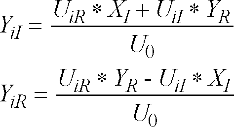
Aus dem ersten Meßvorgang erhält man bei n Antennen für jedes Netz ein Datenfeld mit den komplexen Spannungen U1 bis Un. Ferner sind die komplexe Eingangsspannung U0 und die Kapazität Cp der Sonde bekannt. Der Erfindung liegt die Erkenntnis zugrunde, daß man aus diesenWith n antennas, a data field with the complex voltages U 1 to U n is obtained for each network from the first measurement process. Furthermore, the complex input voltage U 0 and the capacitance C p of the probe are known. The invention is based on the knowledge that one can use these
Daten den komplexen Leitwert (=1/Impedanz) ![]()
![]()
![]()
![]()
Der Realteil und der Imaginärteil des Gesamtleitwertes Y bestimmen sich zu
![]()
![]()
Es hat sich gezeigt, daß die Leitwerte aus den mit der Feldmessung erhaltenen Daten mit einer Genauigkeit von besser als 1,5% ermittelt werden können, so daß sie als Referenzwerte für ein mit einem Leitwertvergleich arbeitendes Meßverfahren geeignet sind.It has been shown that the conductance values can be determined from the data obtained with the field measurement with an accuracy of better than 1.5%, so that they are suitable as reference values for a measurement method working with a conductance comparison.
Beim ersten Meßvorgang werden deshalb gleichzeitig mit der Prüfung einer Leiteranordnung auch die komplexen Leitwerte Yi zwischen den Netzen und den Antennen Ai berechnet. Die Leitwerte Yi bzw. die Kapazitäten Cia werden als Referenzwerte für die nachfolgenden Meßvorgänge abgespeichert.In the first measurement process, the complex conductance values Y i between the networks and the antennas A i are therefore calculated simultaneously with the testing of a conductor arrangement. The guide values Y i and the capacitances C ia are stored as reference values for the subsequent measurement processes.
Es ist auch möglich, anstatt dem Leitwert Yi bzw. der Kapazität Cia zwischen dem Netz Nk und einer einzigen Antenne Ai einen Gesamtleitwert YkG bzw. eine Gesamtkapazität CaG, die zwischen dem Netz Nk und mehreren miteineander elektrisch verbundenen Antennen Ai besteht, aus den Felddaten zu berechnen. Dies ist zweckmäßig, wenn bei den weiteren Meßvorgängen eine Antenne verwendet wird, die aus mehreren miteinander elektrisch kurzgeschlossenen Antennen Ai besteht. Es ist auch möglich, die Datenfelder der Feldmessung abzuspeichern und bei jedem weiteren Meßvorgang die entsprechenden Kapazitäten zu berechnen, so daß die Anordnung der Antennen variiert werden kann.Instead of the conductance Y i or the capacitance C ia between the network N k and a single antenna A i, it is also possible to have a total conductance Y kG or a total capacitance C aG between the network N k and several antennas electrically connected to one another A i consists of calculating from the field data. This is expedient if an antenna is used in the further measuring processes, which consists of several antennas A i which are electrically short-circuited to one another. It is also possible to save the data fields of the field measurement and to calculate the corresponding capacitances with each further measurement process, so that the arrangement of the antennas can be varied.
Die weiteren Meßvorgänge werden durch eine Leitwertmessung der Leitwerte Yk zwischen den Netzen Nk und jeweils einer der Antennen Ai ausgeführt. Diese Ist-Leitwerte Yk werden mit den entsprechenden Referenzwerten verglichen, wobei bei Abweichungen untersucht wird, ob ein Kurzschluß mit einem anderen Netz oder eine Unterbrechung im Netz oder beides vorliegt.The further measurement processes are carried out by measuring the conductance of the conductance values Y k between the networks N k and one of the antennas A i . These actual guide values Y k are compared with the corresponding reference values, and in the event of deviations it is examined whether there is a short circuit with another network or an interruption in the network or both.
Die Bestimmung eines Kurzschlusses kann ähnlich wie bei dem aus dem Stand der Technik (z.B. DE 34 08 704 A1 oder EP 0 438 491 B1) bekannten Impedanzvergleich erfolgen. Hierbei wird die Kapazität bzw. die Impedanz des Netzes gemessen, und bei Abweichungen vom Referenzwert wird eine konventionelle Widerstandsmessung durchgeführt, um den Kurzschluß zu lokalisieren.A short circuit can be determined similarly to the impedance comparison known from the prior art (e.g. DE 34 08 704 A1 or EP 0 438 491 B1). The capacitance or the impedance of the network is measured here, and if there are deviations from the reference value, a conventional resistance measurement is carried out in order to localize the short circuit.
Nachteilig an diesen bekannten mit einem Impedanzvergleich arbeitenden Verfahren ist, daß hochohmige Kurzschlüsse aus dem Impedanzvergleich nicht feststellbar sind. Diese hochohmigen Kurzschlüsse können deshalb nur bei einer visuellen Kontrolle der Leiteranordnung festgestellt werden, die nach einem auf einem Impedanzvergleich beruhenden Meßverfahren unbedingt notwendig ist.A disadvantage of these known methods working with an impedance comparison is that high-resistance short circuits cannot be determined from the impedance comparison. These high-resistance short-circuits can therefore only be determined with a visual inspection of the conductor arrangement, which is after one a measurement method based on an impedance comparison is absolutely necessary.
Die Erfindung sieht deshalb vorzugsweise für die nachfolgenden weiteren Meßvorgänge einen modifizierten Vergleich des gemessenen Leitwertes Yi mit den Referenzwerten zur Bestimmung von Kurzschlüssen vor. Bei den weiteren Meßvorgängen wird eine einfache und schnell ausführbare Messung des Leitwertes Yk vorgesehen, um Kurzschlüsse an den Netzen Nk festzustellen, wobei der Leitwert Yk der Leitwert zwischen dem Netz Nk und der jeweiligen Antenne Ai ist. Im Vergleich zur Feldmessung vermindert sich der Meßaufwand deutlich, da keine Mehrfachabtastung eines Netzes Nk durch mehrere Antennen Ai notwendig ist. Die weiteren Meßvorgänge zur Ermittlung von Kurzschlüssen zwischen den einzelnen Netzen Nk beruhen somit auf der einfach und schnell durchführbaren Messung des Leitwertes Yk, wobei auch hochohmige Kurzschlüsse festgestellt werden können. Wird ein Kurzschluß an einem Netz festgestellt, dann wird er in bekannter Art und Weise mit einer Widerstandsmessung lokalisiert.The invention therefore preferably provides a modified comparison of the measured conductance Y i with the reference values for the determination of short circuits for the subsequent further measurement processes. In the further measuring processes, a simple and quickly executable measurement of the conductance Y k is provided in order to determine short circuits on the networks N k , the conductance Y k being the conductance between the network N k and the respective antenna A i . Compared to field measurements, the measurement effort is significantly reduced since no multiple scanning of a network N k by several antennas A i is necessary. The further measuring processes for determining short circuits between the individual networks N k are thus based on the measurement of the conductance Y k , which can be carried out simply and quickly, and high-resistance short circuits can also be determined. If a short circuit is found on a network, it is localized in a known manner with a resistance measurement.
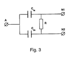
Der erfindungsgemäße Meßvorgang zur Ermittlung, ob zwischen einem Netz N1 und einem beliebigen anderen Netz N2 ein Kurzschluß besteht, wird nachfolgend anhand des in Fig. 3 dargestellten Ersatzschaltbildes erläutert. Hierbei wird vom Leitwert Y1 zwischen der Antenne A und dem Netz N1 ausgegangen, wobei C1a und C2a die jeweiligen Kapazitäten (=Referenzwerte) zwischen der Antenne A und den Netzen N1 und N2, und R den Widerstand (=unbekannte Größe) zwischen den beiden Netzen darstellen. Für den komplexen Leitwert gilt:
Durch eine geschickte Umformung ergibt sich:
Berücksichtigt man die Meßabweichungen ΔY für den gemessenen Leitwert Y1, die maximale Abweichung ΔC zwischen den Kapazitäten der gleichen Netze unterschiedlicher Leiteranordnungen, und setzt man für den Widerstand R einen Schwellenwert RTK ein und wählt man C2a ≥ C1a, so kann man obige Gleichung in folgende Ungleichung umformen:
Die Werte ΔY und ΔC sind Erfahrungswerte, die von der verwendeten Meßvorrichtung und der Art der Leiteranordnung abhängen.The values Δ Y and Δ C are empirical values that depend on the measuring device used and the type of the conductor arrangement.
Die Bedingung C2a ≥ C1a läßt sich einfach durch Austausch der entsprechenden Netze N erfüllen.The condition C 2a ≥ C 1a can be met simply by exchanging the corresponding networks N.
Ist der tatsächliche Widerstand R zwischen dem Netz N1 und allen anderen Netzen Nk größer als der Schwellenwert RTK, so ist obige Ungleichung (8) erfüllt, und es steht fest, daß vom Netz N1 kein Kurzschluß zu einem größeren Netz bzw. einem Netz mit größerer Kapazität besteht.If the actual resistance R between the network N 1 and all other networks N k is greater than the threshold value R TK , the above inequality (8) is satisfied and it is certain that there is no short circuit from the network N 1 to a larger network or a network with larger capacity.
Bei den üblichen Frequenzen (z.B.: 2πω = 2 kHz) gilt für Netze mit kleiner Kapazität C1a für Schwellenwerte RTK bis zu 10 MΩ![]()
![]()
![]()
![]()
Unterbrechungen in den Netzen Nk können in den weiteren Meßvorgängen entweder durch eine an sich bekannte Widerstandsmessung oder durch einen Vergleich des Ist-Leitwertes Yk bzw. der Ist-Kapazität Ck mit den abgespeicherten Referenzwerten erfolgen. Interruptions in the networks N k can occur in the further measuring processes either by a resistance measurement known per se or by comparing the actual conductance Y k or the actual capacitance C k with the stored reference values.
Die zu untersuchenden Netze haben oft L=20.000 oder mehr Prüfpunkte. Greift man alle Prüfpunkte paarweise für einen Unterbrechungstest mittels Widerstandsmessung ab, so sind L-1 Messungen pro Netz notwendig. Hierbei werden die Prüfpunkte jeweils paarweise abgegriffen, wobei zur Optimierung der Anzahl der Messungen nur bestimmte Paare von Prüfpunkten abgegriffen werden können, so daß Meßfinger, die die Prüfpunkte abgreifen, nur in einer vorbestimmten Art und Weise paarweise bewegt werden. Um den Meßvorgang zu vereinfachen, ist es auch bekannt, Unterbrechungen mittels eines Kapazitätsvergleichs zu ermitteln (US 3,975,680). Hierbei wird jeder Prüfpunkt einmal mit einem Meßfinger kontaktiert, wobei die Prüfpunkte in beliebiger Reihenfolge abgegriffen werden, so daß sich die Bewegungen der Meßfinger wesentlich vereinfachen.The networks to be examined often have L = 20,000 or more test points. If you tap all test points in pairs for an interruption test using resistance measurement, L-1 measurements per network are necessary. In this case, the test points are tapped in pairs, and in order to optimize the number of measurements, only certain pairs of test points can be tapped, so that measuring fingers tapping the test points are only moved in pairs in a predetermined manner. In order to simplify the measuring process, it is also known to determine interruptions by means of a capacity comparison (US 3,975,680). Here, each test point is contacted once with a measuring finger, the test points being picked up in any order, so that the movements of the measuring fingers are considerably simplified.
Erfindungsgemäß wird deshalb vorgeschlagen, den an den Prüfpunkten gemessenen Leitwert Yi mit dem entsprechenden Referenzwert zu vergleichen, wobei dieses Verfahren nur an ausreichend großen Netzen mit einer ausreichend hohen Kapazität durchgeführt wird.It is therefore proposed according to the invention to compare the conductance Y i measured at the test points with the corresponding reference value, this method being carried out only on sufficiently large networks with a sufficiently high capacity.
Das erfindungsgemäße Meßverfahren zur Ermittlung von Unterbrechungen wird wiederum an dem in Fig. 3 dargestellten Ersatzschaltbild erläutert, wobei angenommen wird, daß das zu untersuchende Netz in zwei Teilnetze N1 und N2 unterteilt ist, die durch die zu ermittelnde Unterbrechung mit dem Widerstand R voneinander getrennt sind. Für die als Referenzwert abgespeicherte Gesamtkapazität gilt ![]()
![]()
Für den am Teilnetz N1 gemessenen Leitwert Y1 gilt:
so daß aus (11) für den am Teilnetz N1 gemessenen Leitwert abge-

so that from (11) for the conductance measured at subnet N 1
Die Differenz des gemessenen Leitwertes zu dem Referenzwert ist:
Vergleicht man die Werte des Imaginär- und des Realteils in![]()
![]()
![]()
![]()
![]()
![]()
Der Realteil kann wahrgenommen werden, wenn gemäß (15)![]()
![]()
![]()
![]()
Für das Kriterium, ob ein Netz mit einem Leitwertvergleich auf Unterbrechungen untersucht werden kann, ergibt sich somit:![]()
![]()
Für typische Werte von RTU=1 kΩ, δ=0,3% und ω=2π*2.000 1/s ergibt sich eine Mindestkapazität von etwa 1nF. Solche Kapazitäten werden im Allgemeinen von größeren Leiterbahnanordnungen mit einigen Hundert oder mehr Prüfpunkten erreicht.For typical values of R TU = 1 kΩ, δ = 0.3% and ω = 2π * 2,000 1 / s, the minimum capacitance is about 1nF. Such capacities are generally achieved by larger track layouts with a few hundred or more test points.
Für die Erstellung der Prüfkriterien wird davon ausgegenagen, daß α≤1 und somit ![]()
![]()
![]()
![]()
![]()
![]()
Sind die beiden Ungleichungen (18) und (19) erfüllt, so liegt keine Unterbrechung vor. Die Unterbrechung kann mit einer an sich bekannten Widerstandsmessung lokalisiert werden.If the two inequalities (18) and (19) are satisfied, there is no interruption. The interruption can be localized using a resistance measurement known per se.
Das Meßverfahren für die weiteren Meßvorgänge kann somit für ausreichend große Netze, die die Ungleichung (17) erfüllen, folgendermaßen zusammengefaßt werden:
- 1.) An allen Prüfpunkten wird der Leitwert Yk gemessen.
- 2.) Falls alle Leitwerte identisch sind und mit dem Referenzwert übereinstimmen, dann weist das Netz weder einen Kurzschluß noch eine Unterbrechung auf.
- 3.) Weicht ein Leitwert vom Referenzwert ab, so wird er den Prüfkriterien gemäß der Ungleichung (8) zum Feststellen von Kurzschlüssen bzw. gemäß den Ungleichungen (18) und (19) zum Feststellen von Unterbrechungen zugeführt, so daß die Art des Fehlers bestimmt wird.
- 4.) Ein festgestellter Kurzschluß bzw. eine festgestellte Unterbrechung kann dann in an sich bekannter Art und Weise mit einer Widerstandsmessung lokalisiert werden.
- 1.) The conductance Y k is measured at all test points.
- 2.) If all the master values are identical and match the reference value, then the network has neither a short circuit nor an interruption.
- 3.) If a master value deviates from the reference value, it is supplied to the test criteria in accordance with inequality (8) for the detection of short circuits or in accordance with inequalities (18) and (19) for the detection of interruptions, so that the type of error is determined becomes.
- 4.) A detected short circuit or a detected interruption can then be localized in a manner known per se with a resistance measurement.
Bei kleineren Netzen, die nicht die Ungleichung (17) erfüllen, wird vorzugsweise folgendes Meßverfahren durchgeführt:
- 1.) An dem zu untersuchendem Netz Nk wird ein Leitwert Yk gemessen.
- 2.) Falls der Leitwert vom Referenzwert abweicht, wird er dem Prüfkriterium nach der Ungleichung (8) zugeführt, und falls ein Kurzschluß festgestellt wird, wird der Kurzschluß mit einer Widerstandsmessung lokalisiert.
- 3.) Unterbrechungen werden in an sich bekannter Weise durch Widerstandsmessungen ermittelt, wobei alle Prüfpunkte paarweise abgegriffen werden.
- 1.) A conductance Y k is measured on the network N k to be examined.
- 2.) If the conductance deviates from the reference value, it is applied to the test criterion according to inequality (8), and if a short circuit is found, the short circuit is localized with a resistance measurement.
- 3.) Interruptions are determined in a manner known per se by resistance measurements, with all test points being tapped in pairs.
Für diese Art der Ermittlung von Kurzschlüssen und Unterbrechungen ist es notwendig, daß Referenzkapazitäten vorliegen. Diese müssen selbstverständlich nicht durch eine Feldmessung bestimmt werden, sondern können auch mit den zur Bestimmung von Referenzimpedanzen bekannten Verfahren ermittelt werden.For this type of detection of short circuits and interruptions, it is necessary to have reference capacities. Of course, these do not have to be determined by a field measurement, but can also be determined using the methods known for determining reference impedances.
Sollten beim ersten Meßvorgang eines oder mehrere Netze defekt sein, so wird unterschieden, ob mehr oder weniger als eine vorbestimmte Anzahl g Netze defekt sind. Sind mehr als die vorbestimmte Anzahl g von Netzen defekt, so wird mit einer weiteren Leiteranordnung die Feldmessung wiederholt, wobei die fehlenden Referenzwerte durch die neuen Messungen an nicht defekten Netzen ergänzt werden. Sind weniger als die vorbestimmte Anzahl von Netzen defekt, so wird ein weiterer Meßvorgang ausgeführt, bei dem der komplexe Leitwert Yk gemessen wird, wobei durch Widerstandsmessungen am Netz bzw. zwischen den Netzen oder durch einen Vergleich des Imaginärteils YkI bzw. der Kapazität Cka des beim ersten Meßvorgang defekten Netzes mit den Kapazitäten der übrigen Netze und einer eventuell auszuführenden Widerstandsmessung zwischen Netzen gleicher Kapazität festgestellt werden kann, ob am gleichen Netz wiederum ein Defekt vorliegt. Ist das Netz nicht defekt, so wird der gemessene Leitwert Yk bzw. die gemessene Kapazität Cka als Referenzwert abgespeichert.If one or more networks are defective during the first measurement process, a distinction is made as to whether more or less than a predetermined number g networks are defective. If more than the predetermined number g of networks are defective, the field measurement is repeated with a further conductor arrangement, the missing reference values being supplemented by the new measurements on non-defective networks. If fewer than the predetermined number of networks are defective, a further measurement process is carried out in which the complex conductance Y k is measured, by measuring the resistance on the network or between the networks or by comparing the imaginary part Y kI or the capacitance C. ka of the network defective in the first measurement process with the capacities of the other networks and a possibly to be carried out resistance measurement between networks of the same capacity, it can be determined whether there is again a defect in the same network. If the network is not defective, the measured conductance Y k or the measured capacitance C ka is stored as a reference value.
Eine Vorrichtung zur Ausführung des Verfahrens weist mehrere Elektroden 1 auf, die mit Prüfpunkten 2 der Netze Nk auf einer Leiteranordnung 3 kontaktiert werden können (Fig. 2,4). Die Elektroden 1 sind vorzugsweise als Antennensonden und als Meßsonden verwendbar. Als Antennensonden legen sie an die mit ihnen verbundenen Netze entweder die Eingangsspannung U0 oder Masse an, so daß die mit ihnen verbundenen Netze als Antennen wirken. Die Meßsonde greift die an dem mit ihr verbundenen Netz anliegende Spannung Ui ab.A device for carrying out the method has a plurality of
Eine bevorzugte Ausführungsform der Meßvorrichtung ist ein sogenanntes an sich bekanntes Multi-Finger-System (Fig. 4), bei dem jeweils eine Elektrode 1 in einen Meßfinger 4 integriert ist. Ein Multi-Finger-System, bei dem die Meßfinger unabhängig voneinander verfahrbar sind, ist in der EP 0 468 153 A1 beschrieben. Die Meßfinger 4 können parallel zur Oberfläche der Leiteranordnung 3 verschoben werden, so daß die Elektroden mit bestimmten Prüfpunkten 2 der Netze Nk kontaktiert werden können. Ein solches Multi-Finger-System weist bspw. 16 Meßfinger 4 auf, wobei acht oberhalb und acht unterhalb der Leiteranordnung 3 angeordnet sind, um die Leiteranordnung 3 von beiden Seiten zu kontaktieren. Die Meßfinger 4 sind jeweils an einem durch eine Positionssteuereinrichtung 5 gesteuerten Schlitten 6 befestigt, der in einer Ebene parallel zur Leiteranordnung 3 verfahren werden kann. Die Schlitten 6 sind jeweils mit einem vertikal ausgerichteten Stellzylinder 7 versehen, mit dem die Meßfinger 4 um die vertikale Achse gedreht werden können. Ferner ist in den Meßfingern 4 eine Kippeinrichtung integriert, so daß der Finger mit der an seiner Spitze angeordneten Sonde 1 auf die Leiteranordnung 3 abgesenkt werden kann.A preferred embodiment of the measuring device is a so-called multi-finger system (FIG. 4), in which an
Beim ersten Meßvorgang werden eine Feldmessung und eine Widerstandsmessung durchgeführt. Für die Feldmessung wird die Leiteranordnung 3 in bestimmte Segmente unterteilt, wobei für jedes Segment bestimmte Netze dieses Segments als Antennen ausgewählt werden. Die als Antennen ausgewählten Netze sind während des Vermessens dieses Segments jeweils mit einer der Elektroden 1 in Kontakt, wobei die anderen Elektroden 1 abwechselnd jeweils ein Netz des Segments zur Aufnahme der Meßspannung Ui kontaktieren. Das zu messende Netz wird gleichzeitig an zumindest einem weiteren Prüfpunkt 2 mit einer weiteren Elektrode 1 kontaktiert, so daß der Widerstandswert des Netzes zwischen den beiden Elektroden 1 abgegriffen werden kann. Mit der Widerstandsmessung werden die Netze auf Unterbrechungen überprüft, wobei alle Prüfpunkte an einem Netz paarweise abgegriffen werden.In the first measurement process, a field measurement and a resistance measurement are carried out. For field measurement, the
Die Positionssteuereinrichtung 5 erhält zur Steuerung der Bewegung der Meßfinger 4 ihre Signale von einer zentralen Steuereinheit 8. Bei der Feldmessung werden durch die zentrale Steuereinheit 8 eine Antenne des Segments mit einem Funktionsgenerator 9, der die Meßspannung U0 abgibt, und die anderen Antennen mit Masse in Verbindung gesetzt. Ferner stellt die zentrale Steuereinheit eine Verbindung des zu vermessenden Netzes Nk über eine einzige Elektrode 1 zu einer ersten Auswerteeinrichtung 10 für die Feldmessung her, wobei die Spannung Ui am Netz N abgegriffen wird. Weitere Netze Nk können im Bereich eines Segments abgetastet werden, ohne daß hierzu die mit den Antennen in Verbindung stehenden Elektroden 1, sondern nur die Elektroden 1 zur Kontaktierung der zu messenden Netze bewegt werden.The
Für die Widerstandsmessung werden alle Prüfpunkte 2 des Netzes Nk jeweils mit einer Elektrode 1 paarweise in Verbindung gebracht. Der Widerstandswert dieses Netzes wird von einer zweiten Auswerteeinrichtung 11 aufgenommen und zu der zentralen Steuereinheit weitergeleitet.For the resistance measurement, all
Im ersten Meßvorgang werden somit die mit den Antennen in Verbindung stehenden Elektroden 1 nicht bewegt, und die anderen Elektroden 1 mit den zu messenden Netzen kontaktiert.In the first measurement process, the
Die erste Auswerteeinrichtung 10 nimmt die abgegriffenen Spannungen Ui (Feldmessung) auf und leitet sie zur zentralen Steuereinheit weiter, die die Referenzleitwerte ermittelt und abspeichert.The
Bei den weiteren Meßvorgängen wird bei ausreichend großen Netzen, die die Ungleichung (17) erfüllen, an jedem Prüfpunkt 2 als Leitwert Yk nur ein einziger Widerstandswert und ein Kapazitätswert zwischen dem Netz und der Antenne gemessen. Die Induktivität der Netze ist so gering, daß sie vernachlässigt werden kann.In the further measuring processes, with sufficiently large networks which satisfy the inequality (17), only one resistance value and one capacitance value between the network and the antenna are measured at each
Die Meßfinger 4 werden so angesteuert, daß in einem Segment eine einzige Elektrode 1 mit einer Antenne bzw. einer Antennenkombination in Verbindung steht, und die anderen Meßfinger 4 mit ihren Elektroden 1 die zu vermessenden Prüfpunkte 2 abtasten, so daß mit einer dritten Auswerteeinrichtung 12 die Kapazitäten Ck bzw. der Imaginärteil des Leitwertes YkI zwischen der Antenne A und dem zu messenden Netz Nk an dem jeweiligen Prüfpunkt 2 aufgenommen wird. Mit der zweiten Auswerteeinrichtung 11 wird der Widerstand bzw. der Realteil YkR zwischen der Antenne A und dem zu messenden Netz Nk erfaßt.The measuring
Bei großen Netzen wird somit bei einem weiteren Meßvorgang eine Sonde 1 permanent mit einer Antenne kontaktiert, und alle Prüfpunkte 2 werden jeweils ein einziges mal mit einer Sonde 1 zur Aufnahme des Leitwertes kontaktiert.In the case of large networks, a
Bei kleineren Netzen, die die Ungleichung (17) nicht erfüllen, wird zuerst eine Leitwertmessung zwischen der Antenne A und dem Netz Nk ausgeführt, wozu eine Sonde 1 mit einer Antenne und eine weitere Sonde 1 mit einem Prüfpunkt 2 des Netzes kontaktiert werden. Zur Feststellung von Unterbrechungen werden alle Prüfpunkte paarweise mit zwei Sonden 1 kontaktiert.In the case of smaller networks which do not meet the inequality (17), a conductance measurement is first carried out between the antenna A and the network N k , for which purpose a
Die zweite und dritte Auswerteeinrichtung 11, 12 zum Wahrnehmen eines Widerstandes bzw. einer Kapazität beruhen im Gegensatz zur ersten Auswerteeinrichtung 10, die mit einer Spannungsmessung die Feldwerte aufnimmt, auf einer Strommessung. Durch das Vorsehen der drei Auswerteeinrichtungen 10, 11, 12 in einer Meßvorrichtung ist es möglich, das erfindungsgemäße Verfahren, das sowohl auf einer Feldmessung als auch auf einer Leitwertmessung beruht, durchzuführen.In contrast to the
Ein Multi-Finger-System, dessen zentrale Steuereinheit 8 zur Ausführung der erfindungsgemäßen Verfahren ausgebildet ist, muß im Vergleich zu bekannten Multi-Finger-Systemen eine viel geringere Anzahl von Bewegungen der Meßfinger 4 beim Vermessen gleicher Leiteranordnungen ausführen, da Kurzschlüsse mit einer einzigen Leitwertmessung pro Netz, und bei größeren Netzen Unterbrechungen mit einer Leitwertmessung pro Prüfpunkt detektiert werden können. Die durch die Erfindung erzielten Verbesserungen beruhen u.a. darauf, daß die Leitwerte und nicht wie im Stand der Technik deren Kehrwerte, die Impedanzen, untersucht werden, wodurch die darin enthaltenen Informationen effektiver ausgewertet werden können.A multi-finger system, the central control unit 8 of which is designed to carry out the method according to the invention, has to carry out a much smaller number of movements of the measuring
Claims (23)
dadurch gekennzeichnet,
daß während des ersten Meßvorgangs aus den sich bei der Feldmessung ergebenden Datensätzen die komplexen Leitwerte ermittelt und als Referenzwerte abgespeichert werden.Method according to claim 1,
characterized,
that during the first measurement process, the complex guide values are determined from the data records resulting from the field measurement and are stored as reference values.
dadurch gekennzeichnet,
daß die einen Real- und Imaginärteil aufweisenden komplexen Leitwerte nur als Referenzwerte verwendet werden, wenn der Realteil gleich Null ist, wobei dann als Referenzwert der Imaginärteil des Leitwertes abgespeichert wird, der der Kapazität zwischen der Antenne und dem Netz entspricht.The method of claim 1 or 2,
characterized,
that the complex master values having a real and imaginary part are only used as reference values if the real part is zero, the imaginary part of the master value corresponding to the capacitance between the antenna and the network being stored as the reference value.
dadurch gekennzeichnet,
daß bei der Feldmessung mehrere Antennen A1 bis An verwendet werden, wobei beim Vermessen eines Netzes N an die Antennen A1 bis An aufeinanderfolgend jeweils an eine der Antennen Ai eine Eingangsspannung U0 angelegt wird, während die übrigen Antennen mit Masse verbunden sind und an dem Netz N jeweils eine Spannung Ui abgegriffen wird.Method according to one of claims 1 to 3,
characterized,
that are used in the field measurement several antennas A 1 to A n, wherein, when measuring a network N to the antennas A 1 to A n in succession each to one of the antennas A i an input voltage U 0 is applied, while the remaining antennas connected to ground are and a voltage U i is tapped from the network N.
dadurch gekennzeichnet,
daß die Eingangsspannung U0 vorzugsweise eine Sinuswelle mit einer bestimmten Frequenz (bspw. 2πω = 2 kHz) ist, wobei die Amplitude im Bereich von 4 V bis 250 V liegt.Method according to one of claims 1 to 4,
characterized,
that the input voltage U 0 is preferably a sine wave with a certain frequency (for example. 2πω = 2 kHz), the amplitude being in the range from 4 V to 250 V.
dadurch gekennzeichnet,
daß der Referenzleitwert

characterized,
that the reference conductance
dadurch gekennzeichnet,
daß als Antennen A1 bis An Netze der Leiteranordnung verwendet werden.Method according to one of claims 4 to 6,
characterized,
that as antennas A 1 to A n networks of the conductor arrangement are used.
dadurch gekennzeichnet,
daß als Antennen A1 bis An getrennt von der Leiteranordnung ausgebildete Leiterbahnen verwendet werden, die vorzugsweise direkt auf die Leiteranordnung aufgelegt werden können.Method according to one of claims 4 to 6,
characterized,
that as antennas A 1 to A n separately formed conductor tracks are used, which can preferably be placed directly on the conductor arrangement.
dadurch gekennzeichnet,
daß die zu vermessenden Netze N der Leiteranordnung als Antennen verwendet werden und an gegenüber von der Leiteranordnung getrennt ausgebildeten Leiterbahnen die Spannungen Ui abgegriffen werden.Method according to one of claims 4 to 6,
characterized,
that the networks N of the conductor arrangement to be measured are used as antennas and the voltages U i are tapped on conductor paths which are separate from the conductor arrangement.
dadurch gekennzeichnet,
daß wenn mehr als die vorbestimmte Anzahl g von Netzen beim ersten Meßvorgang defekt sind, mit einer weiteren Leiteranordnung die Feldmessung wiederholt wird, wobei die fehlenden Referenzwerte durch die neuen Messungen an nicht defekten Netzen ergänzt werden, und,
daß wenn weniger als die vorbestimmte Anzahl von Netzen defekt, so wird ein weiterer Meßvorgang ausgeführt wird, bei dem der komplexe Leitwert (Yk) gemessen wird, wobei durch einen Vergleich des Leitwertes des beim ersten Meßvorgang defekten Netzes mit den Leitwerten der übrigen Netze und einer eventuell auszuführenden Widerstandsmessung zwischen Netzen mit gleichem Leitwert festgestellt wird, ob am gleichen Netz wiederum ein Defekt vorliegt, und wenn dies nicht der Fall sein sollte, so wird der gemessene Leitwert (Yk) als Referenzwert abgespeichert.Method according to one of claims 1 to 9,
characterized,
that if more than the predetermined number g of networks are defective in the first measurement process, the field measurement is repeated with a further conductor arrangement, the missing reference values being supplemented by the new measurements on non-defective networks, and,
that if fewer than the predetermined number of networks are defective, a further measurement process is carried out in which the complex conductance (Y k ) is measured, by comparing the conductance of the network defective in the first measurement process with the conductance values of the other networks and If a resistance measurement is to be carried out between networks with the same conductance value, it is determined whether there is again a defect in the same network, and if this should not be the case, the measured conductance value (Y k ) is stored as a reference value.
dadurch gekennzeichnet,
daß aus den sich bei der Feldmessung ergebenden Datensätzen ein komplexer Gesamleitwert (YkG) zwischen mehreren der bei der Feldmessung verwendeten Antennen (Ai) und einem der gemessene Netze Nk ermittelt wird, und
die Antennen (Ai), die dem Gesamtleitwert (YkG) zugrunde liegen, bei den weiteren Meßvorgängen zu einer einzigen Antenne elektrisch verbunden werden.Method according to one of claims 1 to 10,
characterized,
that a complex overall conductance (Y kG ) between several of the antennas (A i ) used in the field measurement and one of the measured networks N k is determined from the data sets resulting from the field measurement, and
the antennas (A i ), on which the overall conductance (Y kG ) is based, are electrically connected to a single antenna in the further measuring processes.
dadurch gekennzeichnet,
daß beim Vergleich des Ist-Leitwertes und des Referenzleitwertes nur die in den Leitwerten enthaltenen Kapazitäten in an sich bekannter Weise miteinander verglichen werden.Method according to one of claims 1 to 11,
characterized,
that when comparing the actual conductance and the reference conductance, only the capacitances contained in the conductance are compared with one another in a manner known per se.
dadurch gekennzeichnet,
daß der Vergleich auf folgender Ungleichung beruht

characterized,
that the comparison is based on the following inequality
dadurch gekennzeichnet,
daß, wenn ein Kurzschluß festgestellt wird, eine Widerstandsmessung durchgeführt wird, um den Kurzschluß zu lokalisieren.The method of claim 13 or 14,
characterized,
that if a short is detected, a resistance measurement is made to locate the short.
dadurch gekennzeichnet,
daß der Vergleich auf folgenden Ungleichungen beruht

characterized,
that the comparison is based on the following inequalities
dadurch gekennzeichnet,
daß der Vergleich der Leitwerte zur Ermittlung von Unterbrechungen nur an Netzen durchgeführt wird, die folgender Ungleichung genügen
characterized,
that the comparison of the guide values for the determination of interruptions is only carried out on networks that satisfy the following inequality
dadurch gekennzeichnet,
daß an Netzen, an welchen Unterbrechungen nicht durch einen Leitwertvergleich ermittelt werden, die Unterbrechungen durch eine an sich bekannte Widerstandsmessung ermittelt werden.Method according to claim 18,
characterized,
that on networks on which interruptions are not determined by a conductance comparison, the interruptions are determined by a resistance measurement known per se.
mit
Elektroden (1), die mit vorbestimmten Prüfpunkten (2) an Netzen einer Leiteranordnung kontaktiert werden können, einem Funktionsgenerator (9) zum Abgeben einer Eingangsspannung (U0) an eine Antenne (Ai),
einer ersten Auswerteeinrichtung (10) zum Ausführen einer Feldmessung, wobei eine Spannung (Ui) an dem zu messenden Netz (Nk) abgegriffen wird, und
einer zweiten Auswerteeinrichtung (11) zum Ausführen einer Widerstandsmessung zwischen dem Netz und der Antenne, dadurch gekennzeichnet,
daß die Vorrichtung eine dritte Auswerteeinrichtung (12) zum Ausführen einer Kapazitätsmessung zwischen dem Netz und der Antenne aufweist, so daß aus dem ermittelten Widerstandswert und dem ermittelten Kapazitätswert der komplexe Leitwert (Yk) zwischen dem Netz und der Antenne gebildet werden kann.Device for carrying out a method according to claims 1 to 19,
With
Electrodes (1) which can be contacted with predetermined test points (2) on networks of a conductor arrangement, a function generator (9) for delivering an input voltage (U 0 ) to an antenna (A i ),
a first evaluation device (10) for carrying out a field measurement, a voltage (U i ) on the network to be measured (N k ) being tapped, and
a second evaluation device (11) for carrying out a resistance measurement between the network and the antenna, characterized in that
that the device has a third evaluation device (12) for performing a capacitance measurement between the network and the antenna, so that the complex conductance (Y k ) between the network and the antenna can be formed from the determined resistance value and the determined capacitance value.
gekennzeichnet durch
mehrere Meßfinger (4), in die jeweils eine Elektrode (1) integriert ist, und die mittels einer Positioniereinrichtung (5) entlang einer Leiteranordnung (3) verfahren werden können, und
eine zentrale Steuereinheit (8), die die Positioniereinrichtung (5), den Funktionsgenerator (9) und die drei Auswerteeinrichtungen (10, 11, 12) so steuert,
daß in einem ersten Meßvorgang eine Feldmessung ausgeführt wird, um Kurzschlüsse zwischen den zu vermessenden Netzen in der Leiteranordnung festzustellen, und
die erste Auswerteeinrichtung (18) aufgrund der bei der Feldmessung ermittelten Datensätze die komplexen Leitwerte zwischen den gemessenen Netzen und den jeweiligen Antennen ermittelt, die als Referenzleitwerte abspeichert werden, so daß die weiteren Meßvorgänge zur Ermittlung von Kurzschlüssen und/oder Unterbrechungen durch Vergleich eines gemessenen komplexen Ist-Leitwertes mit einem komplexen Referenzleitwert ausgeführt werden können.Device according to claim 20,
marked by
several measuring fingers (4), in each of which an electrode (1) is integrated, and which can be moved along a conductor arrangement (3) by means of a positioning device (5), and
a central control unit (8) which controls the positioning device (5), the function generator (9) and the three evaluation devices (10, 11, 12),
that a field measurement is carried out in a first measurement process is used to determine short circuits between the networks to be measured in the conductor arrangement, and
the first evaluation device (18) determines the complex conductance values between the measured networks and the respective antennas, which are stored as reference conductance values, on the basis of the data records determined during the field measurement, so that the further measurement processes for determining short circuits and / or interruptions by comparing a measured complex Actual master values can be executed with a complex reference master value.
dadurch gekennzeichnet,
daß die Vorrichtung mehrere Meßfinger (4), vorzugsweise acht oder mehr Meßfinger (4), aufweist, wobei die Meßfinger (4) vorzugsweise auf beiden Seiten der Leiteranordnung (3) angeordnet sind.Device according to claim 21,
characterized,
that the device has a plurality of measuring fingers (4), preferably eight or more measuring fingers (4), the measuring fingers (4) preferably being arranged on both sides of the conductor arrangement (3).
dadurch gekennzeichnet,
daß die zentrale Steuereinheit (8) so ausgebildet ist, daß bei dem in den weiteren Meßvorgängen durchgeführten Vergleich zwischen dem komplexen Ist-Leitwert und dem komplexen Referenzleitwert der Realteil des Ist-Leitwertes mit berücksichtigt wird.Device according to one of claims 19 to 22,
characterized,
that the central control unit (8) is designed such that the real part of the actual master value is also taken into account in the comparison between the complex actual master value and the complex reference master value carried out in the further measuring processes.
Applications Claiming Priority (2)
| Application Number | Priority Date | Filing Date | Title |
|---|---|---|---|
| DE19541307A DE19541307C2 (en) | 1995-11-06 | 1995-11-06 | Method for testing electrical conductor arrangements and device for carrying out the method |
| DE19541307 | 1995-11-06 |
Publications (3)
| Publication Number | Publication Date |
|---|---|
| EP0772054A2 true EP0772054A2 (en) | 1997-05-07 |
| EP0772054A3 EP0772054A3 (en) | 1998-02-25 |
| EP0772054B1 EP0772054B1 (en) | 2003-04-23 |
Family
ID=7776743
Family Applications (1)
| Application Number | Title | Priority Date | Filing Date |
|---|---|---|---|
| EP96117642A Expired - Lifetime EP0772054B1 (en) | 1995-11-06 | 1996-11-04 | Method and device for testing an electric conductor arrangement |
Country Status (4)
| Country | Link |
|---|---|
| US (1) | US5903160A (en) |
| EP (1) | EP0772054B1 (en) |
| JP (1) | JP3183195B2 (en) |
| DE (2) | DE19541307C2 (en) |
Cited By (5)
| Publication number | Priority date | Publication date | Assignee | Title |
|---|---|---|---|---|
| EP0919820A2 (en) * | 1997-10-30 | 1999-06-02 | Nidec-Read Corporation | Circuit board testing apparatus and method |
| DE10260238A1 (en) * | 2002-12-20 | 2004-07-22 | Atg Test Systems Gmbh & Co.Kg | Adapter for testing printed circuit boards |
| WO2006133808A1 (en) | 2005-06-17 | 2006-12-21 | Atg Test Systems Gmbh | Method of testing unloaded, large-area printed circuit boards with a finger tester |
| WO2010043651A2 (en) * | 2008-10-15 | 2010-04-22 | Dtg International Gmbh | Determination of properties of an electrical device |
| DE202014105674U1 (en) | 2014-11-25 | 2016-02-26 | MR Electronics Ltd. Niederlassung Deutschland | Contacting device for boards |
Families Citing this family (8)
| Publication number | Priority date | Publication date | Assignee | Title |
|---|---|---|---|---|
| DE19541307C2 (en) * | 1995-11-06 | 2001-09-27 | Atg Test Systems Gmbh | Method for testing electrical conductor arrangements and device for carrying out the method |
| DE19610556A1 (en) * | 1996-03-18 | 1997-09-25 | Siemens Ag | Bus segment or bus interface for connecting a module of a programmable logic controller to a bus |
| DE10025751A1 (en) * | 2000-05-24 | 2001-12-06 | Atg Test Systems Gmbh | Method for examining a circuit board on a predetermined area of the circuit board and device for carrying out the method |
| US7030623B1 (en) | 2004-02-03 | 2006-04-18 | Kevin Carpenter | Electrical short tracing apparatus and method |
| US10191108B2 (en) * | 2015-11-19 | 2019-01-29 | Globalfoundries Inc. | On-chip sensor for monitoring active circuits on integrated circuit (IC) chips |
| DE102017102700A1 (en) * | 2017-02-10 | 2018-09-13 | Atg Luther & Maelzer Gmbh | Test apparatus and method for testing printed circuit boards |
| JP6386606B1 (en) * | 2017-02-27 | 2018-09-05 | ファナック株式会社 | Connection circuit of connected equipment |
| JP7227017B2 (en) * | 2019-01-29 | 2023-02-21 | 北陸電力株式会社 | Failure determination method for lightning arrester and failure determination device for lightning arrester |
Citations (4)
| Publication number | Priority date | Publication date | Assignee | Title |
|---|---|---|---|---|
| US3975680A (en) | 1975-06-25 | 1976-08-17 | Honeywell Information Systems, Inc. | Non-contact coupling plate for circuit board tester |
| DE3408704A1 (en) | 1983-03-07 | 1984-09-13 | Kollmorgen Technologies Corp., Dallas, Tex. | METHOD AND DEVICE FOR TESTING CONNECTION NETWORK CIRCUITS |
| EP0438491B1 (en) | 1988-10-17 | 1994-07-20 | Bath Scientific Limited | Testing electrical circuits |
| EP0508062B1 (en) | 1991-04-10 | 1995-07-19 | atg test systems GmbH | Method and device for testing an arrangement of electrical conductors |
Family Cites Families (11)
| Publication number | Priority date | Publication date | Assignee | Title |
|---|---|---|---|---|
| DE2311903A1 (en) * | 1973-03-09 | 1974-09-12 | Siemens Ag | PROCEDURE AND EQUIPMENT FOR LOCATING SHORT CIRCUITS IN MULTI-LAYER WIRING |
| US4528500A (en) * | 1980-11-25 | 1985-07-09 | Lightbody James D | Apparatus and method for testing circuit boards |
| EP0246034A3 (en) * | 1986-05-16 | 1989-04-05 | AT&T Corp. | Method of testing electronic assemblies while they are being produced |
| JPH0246034A (en) * | 1988-08-06 | 1990-02-15 | Mitsubishi Electric Corp | Data multiplexer |
| CA2049616C (en) * | 1991-01-22 | 2000-04-04 | Jacob Soiferman | Contactless test method and system for testing printed circuit boards |
| US5424633A (en) * | 1991-01-22 | 1995-06-13 | Advanced Test Technologies Inc. | Contactless test method and system for testing printed circuit boards |
| DE4134193A1 (en) * | 1991-04-10 | 1992-10-15 | Atg Electronic Gmbh | Testing electrical conductor arrangement, esp. on circuit board |
| EP0527321A1 (en) * | 1991-08-05 | 1993-02-17 | Siemens Aktiengesellschaft | Method for automatic error diagnosis of electrical circuit boards |
| US5631572A (en) * | 1993-09-17 | 1997-05-20 | Teradyne, Inc. | Printed circuit board tester using magnetic induction |
| DE69528482T2 (en) * | 1994-01-12 | 2003-07-10 | Advantest Corp | Contactless wave signal monitoring device |
| DE19541307C2 (en) * | 1995-11-06 | 2001-09-27 | Atg Test Systems Gmbh | Method for testing electrical conductor arrangements and device for carrying out the method |
-
1995
- 1995-11-06 DE DE19541307A patent/DE19541307C2/en not_active Expired - Lifetime
-
1996
- 1996-11-04 EP EP96117642A patent/EP0772054B1/en not_active Expired - Lifetime
- 1996-11-04 DE DE59610371T patent/DE59610371D1/en not_active Expired - Lifetime
- 1996-11-05 US US08/743,196 patent/US5903160A/en not_active Expired - Lifetime
- 1996-11-06 JP JP29383396A patent/JP3183195B2/en not_active Expired - Lifetime
Patent Citations (4)
| Publication number | Priority date | Publication date | Assignee | Title |
|---|---|---|---|---|
| US3975680A (en) | 1975-06-25 | 1976-08-17 | Honeywell Information Systems, Inc. | Non-contact coupling plate for circuit board tester |
| DE3408704A1 (en) | 1983-03-07 | 1984-09-13 | Kollmorgen Technologies Corp., Dallas, Tex. | METHOD AND DEVICE FOR TESTING CONNECTION NETWORK CIRCUITS |
| EP0438491B1 (en) | 1988-10-17 | 1994-07-20 | Bath Scientific Limited | Testing electrical circuits |
| EP0508062B1 (en) | 1991-04-10 | 1995-07-19 | atg test systems GmbH | Method and device for testing an arrangement of electrical conductors |
Cited By (14)
| Publication number | Priority date | Publication date | Assignee | Title |
|---|---|---|---|---|
| EP0919820A3 (en) * | 1997-10-30 | 2000-02-02 | Nidec-Read Corporation | Circuit board testing apparatus and method |
| EP0919820A2 (en) * | 1997-10-30 | 1999-06-02 | Nidec-Read Corporation | Circuit board testing apparatus and method |
| DE10260238B4 (en) * | 2002-12-20 | 2007-04-05 | Atg Test Systems Gmbh & Co.Kg | Adapter for testing one or more ladder arrangements and methods |
| DE10260238A1 (en) * | 2002-12-20 | 2004-07-22 | Atg Test Systems Gmbh & Co.Kg | Adapter for testing printed circuit boards |
| DE102005028191B4 (en) * | 2005-06-17 | 2009-04-09 | Atg Luther & Maelzer Gmbh | Method and device for testing unpopulated, large-area circuit boards with a finger tester |
| DE102005028191A1 (en) * | 2005-06-17 | 2006-12-28 | Atg Test Systems Gmbh & Co. Kg Reicholzheim | Method for testing unpopulated, large-area circuit boards with a finger tester |
| WO2006133808A1 (en) | 2005-06-17 | 2006-12-21 | Atg Test Systems Gmbh | Method of testing unloaded, large-area printed circuit boards with a finger tester |
| WO2010043651A2 (en) * | 2008-10-15 | 2010-04-22 | Dtg International Gmbh | Determination of properties of an electrical device |
| WO2010043651A3 (en) * | 2008-10-15 | 2010-06-17 | Dtg International Gmbh | Determination of properties of an electrical device |
| CN102187239A (en) * | 2008-10-15 | 2011-09-14 | Dtg国际有限公司 | Determination of properties of an electrical device |
| US8704545B2 (en) | 2008-10-15 | 2014-04-22 | Dtg International Gmbh | Determination of properties of an electrical device |
| TWI461711B (en) * | 2008-10-15 | 2014-11-21 | Dtg Int Gmbh | Device and method of determing properties of an electrical device |
| CN102187239B (en) * | 2008-10-15 | 2015-07-22 | Dtg国际有限公司 | Determination of properties of an electrical device |
| DE202014105674U1 (en) | 2014-11-25 | 2016-02-26 | MR Electronics Ltd. Niederlassung Deutschland | Contacting device for boards |
Also Published As
| Publication number | Publication date |
|---|---|
| DE59610371D1 (en) | 2003-05-28 |
| EP0772054B1 (en) | 2003-04-23 |
| DE19541307C2 (en) | 2001-09-27 |
| JPH09178798A (en) | 1997-07-11 |
| JP3183195B2 (en) | 2001-07-03 |
| EP0772054A3 (en) | 1998-02-25 |
| US5903160A (en) | 1999-05-11 |
| DE19541307A1 (en) | 1997-05-15 |
Similar Documents
| Publication | Publication Date | Title |
|---|---|---|
| DE4026295C2 (en) | ||
| EP0285799B1 (en) | Device for the functional electric testing of wiring arrays, in particular of circuit boards | |
| EP0508062B1 (en) | Method and device for testing an arrangement of electrical conductors | |
| DE102007046054B4 (en) | Improved high-precision Rogowski current transformer | |
| DE3408704A1 (en) | METHOD AND DEVICE FOR TESTING CONNECTION NETWORK CIRCUITS | |
| DE69432829T2 (en) | Cable identification device for testing cables in local networks | |
| EP0772054B1 (en) | Method and device for testing an electric conductor arrangement | |
| EP0853242B1 (en) | Method for testing printed-circuit boards | |
| DE102013005939A1 (en) | Measuring resistor and corresponding measuring method | |
| DE2952825A1 (en) | CAPACITIVE AND TOUCH-FREE WORKING MEASURING SYSTEM | |
| DE4317285A1 (en) | Capacitive measuring probe for the determination of workpiece dimensions | |
| DE2744299C2 (en) | Method for electrically testing a conductor track pattern on a substrate | |
| DE3644458C2 (en) | Process for evaluating the process parameters in the production of semiconductor devices, and devices therefor | |
| EP1920263B1 (en) | Method of testing unloaded, large-area printed circuit boards with a finger tester | |
| DE3815009C2 (en) | ||
| DE2701857C2 (en) | ||
| EP1151310B1 (en) | Measuring method for a capacitive measuring system | |
| DE4406674A1 (en) | Method for testing an electrode plate to be tested | |
| DE4234548C1 (en) | Induction loop traffic detection system - uses overlapping loops to detect and classify size and position of vehicles | |
| DE112018004610T5 (en) | Capacitive sensor system | |
| DE102018210568A1 (en) | Sensor device and method for determining an AC voltage | |
| DE4312862A1 (en) | Rotatable capacitance sensor | |
| DE202013103151U1 (en) | Device for non-destructive eddy current testing of a component | |
| DE4134193A1 (en) | Testing electrical conductor arrangement, esp. on circuit board | |
| EP3764054B1 (en) | Sensor arrangement for detecting a deflection of a wire electrode |
Legal Events
| Date | Code | Title | Description |
|---|---|---|---|
| PUAI | Public reference made under article 153(3) epc to a published international application that has entered the european phase |
Free format text: ORIGINAL CODE: 0009012 |
|
| 17P | Request for examination filed |
Effective date: 19961104 |
|
| AK | Designated contracting states |
Kind code of ref document: A2 Designated state(s): DE FR GB IT |
|
| PUAL | Search report despatched |
Free format text: ORIGINAL CODE: 0009013 |
|
| AK | Designated contracting states |
Kind code of ref document: A3 Designated state(s): DE FR GB IT |
|
| RAP1 | Party data changed (applicant data changed or rights of an application transferred) |
Owner name: ATG TEST SYSTEMS GMBH & CO. KG |
|
| 17Q | First examination report despatched |
Effective date: 20020204 |
|
| GRAH | Despatch of communication of intention to grant a patent |
Free format text: ORIGINAL CODE: EPIDOS IGRA |
|
| GRAH | Despatch of communication of intention to grant a patent |
Free format text: ORIGINAL CODE: EPIDOS IGRA |
|
| GRAA | (expected) grant |
Free format text: ORIGINAL CODE: 0009210 |
|
| AK | Designated contracting states |
Designated state(s): DE FR GB IT |
|
| REG | Reference to a national code |
Ref country code: GB Ref legal event code: FG4D Free format text: NOT ENGLISH |
|
| GBT | Gb: translation of ep patent filed (gb section 77(6)(a)/1977) |
Effective date: 20030423 |
|
| REF | Corresponds to: |
Ref document number: 59610371 Country of ref document: DE Date of ref document: 20030528 Kind code of ref document: P |
|
| ET | Fr: translation filed | ||
| PLBE | No opposition filed within time limit |
Free format text: ORIGINAL CODE: 0009261 |
|
| STAA | Information on the status of an ep patent application or granted ep patent |
Free format text: STATUS: NO OPPOSITION FILED WITHIN TIME LIMIT |
|
| 26N | No opposition filed |
Effective date: 20040126 |
|
| REG | Reference to a national code |
Ref country code: DE Ref legal event code: R082 Ref document number: 59610371 Country of ref document: DE Representative=s name: PATRONUS IP PATENT- & RECHTSANWAELTE BERNHARD , DE |
|
| REG | Reference to a national code |
Ref country code: FR Ref legal event code: PLFP Year of fee payment: 20 |
|
| PGFP | Annual fee paid to national office [announced via postgrant information from national office to epo] |
Ref country code: GB Payment date: 20151123 Year of fee payment: 20 Ref country code: DE Payment date: 20151120 Year of fee payment: 20 |
|
| PGFP | Annual fee paid to national office [announced via postgrant information from national office to epo] |
Ref country code: FR Payment date: 20151123 Year of fee payment: 20 |
|
| PGFP | Annual fee paid to national office [announced via postgrant information from national office to epo] |
Ref country code: IT Payment date: 20151130 Year of fee payment: 20 |
|
| REG | Reference to a national code |
Ref country code: DE Ref legal event code: R071 Ref document number: 59610371 Country of ref document: DE |
|
| REG | Reference to a national code |
Ref country code: GB Ref legal event code: PE20 Expiry date: 20161103 |
|
| PG25 | Lapsed in a contracting state [announced via postgrant information from national office to epo] |
Ref country code: GB Free format text: LAPSE BECAUSE OF EXPIRATION OF PROTECTION Effective date: 20161103 |