EP0771679A2 - Automotive air conditioning system with self-diagnosable function - Google Patents
Automotive air conditioning system with self-diagnosable function Download PDFInfo
- Publication number
- EP0771679A2 EP0771679A2 EP96115849A EP96115849A EP0771679A2 EP 0771679 A2 EP0771679 A2 EP 0771679A2 EP 96115849 A EP96115849 A EP 96115849A EP 96115849 A EP96115849 A EP 96115849A EP 0771679 A2 EP0771679 A2 EP 0771679A2
- Authority
- EP
- European Patent Office
- Prior art keywords
- control unit
- target position
- signal
- actuators
- actuator
- Prior art date
- Legal status (The legal status is an assumption and is not a legal conclusion. Google has not performed a legal analysis and makes no representation as to the accuracy of the status listed.)
- Granted
Links
Images


Classifications
-
- B—PERFORMING OPERATIONS; TRANSPORTING
- B60—VEHICLES IN GENERAL
- B60H—ARRANGEMENTS OF HEATING, COOLING, VENTILATING OR OTHER AIR-TREATING DEVICES SPECIALLY ADAPTED FOR PASSENGER OR GOODS SPACES OF VEHICLES
- B60H1/00—Heating, cooling or ventilating [HVAC] devices
- B60H1/00642—Control systems or circuits; Control members or indication devices for heating, cooling or ventilating devices
- B60H1/00814—Control systems or circuits characterised by their output, for controlling particular components of the heating, cooling or ventilating installation
- B60H1/00821—Control systems or circuits characterised by their output, for controlling particular components of the heating, cooling or ventilating installation the components being ventilating, air admitting or air distributing devices
- B60H1/00835—Damper doors, e.g. position control
-
- B—PERFORMING OPERATIONS; TRANSPORTING
- B60—VEHICLES IN GENERAL
- B60H—ARRANGEMENTS OF HEATING, COOLING, VENTILATING OR OTHER AIR-TREATING DEVICES SPECIALLY ADAPTED FOR PASSENGER OR GOODS SPACES OF VEHICLES
- B60H1/00—Heating, cooling or ventilating [HVAC] devices
-
- B—PERFORMING OPERATIONS; TRANSPORTING
- B60—VEHICLES IN GENERAL
- B60H—ARRANGEMENTS OF HEATING, COOLING, VENTILATING OR OTHER AIR-TREATING DEVICES SPECIALLY ADAPTED FOR PASSENGER OR GOODS SPACES OF VEHICLES
- B60H1/00—Heating, cooling or ventilating [HVAC] devices
- B60H1/00642—Control systems or circuits; Control members or indication devices for heating, cooling or ventilating devices
- B60H1/00978—Control systems or circuits characterised by failure of detection or safety means; Diagnostic methods
Definitions
- the present invention relates in general to automotive air conditioning systems including a plurality of identical actuators for driving control doors, and more particularly to the automotive air conditioning systems of a type having a self-diagnosable function.
- the current position signal from the PBR is processed by only the actuator. In other words, the current position signal is not fed back to the control unit.
- operation check for the control door or doors by means of a self-diagnosis has not been carried out.
- an automotive air conditioning system which comprises a heater/cooler unit having therein a plurality of control doors by which various air flow modes are provided; a plurality of identical actuators for actuating the control doors, each actuator including an electric motor for driving the corresponding control door, a position detector for issuing a given signal representative of the angular position assumed by the corresponding control door, and a control circuit for controlling the electric motor based on the given signal as well as a target position signal applied thereto; a control unit for integrally controlling the actuators by means of a bi-directional serial transmission, the control unit issuing the target position signal to each of the actuators and thereafter judging whether the actuator issues or not a target position accomplishment signal which represents that the corresponding control door has been set to the target position; and a display device for displaying the result of the target position accomplishment judgment carried out by the control unit.
- an automotive air conditioning system which includes a heater/cooler unit in which a plurality of control doors are arranged, a plurality of identical actuators each-including an electric motor for driving the corresponding control door, a position detecting means for issuing a voltage signal which represents the current angular position of the corresponding control door and a control circuit for controlling the electric motor based on the voltage signal and a target position signal applied thereto, and a control unit for integrally controlling the identical actuators by means of a bi-directional serial transmission method, the air conditioning system being characterized in that the control unit issues the target position signal to each of the actuators, thereafter judges whether the actuator issues or not a target position accomplishment signal which represents that the corresponding control door has been set to the target position, and thereafter displays the result of the target position accomplishment judgment.
- FIG. 1 there is schematically shown an automotive air conditioning system according to the present invention.
- the system comprises a heater/cooler unit 1 which is conventional in construction.
- the heater/cooler unit 1 generally comprises an intake unit 2, a cooling unit 3 and a heater unit 4.
- the intake unit 2 includes an outside air inlet opening 5 and an inside air inlet opening 6 which are selectively controlled by an air intake door 7. That is, by the air intake door 7, the rated between the outside air amount and inside side amount is controlled.
- An electric blower 8 is arranged at a position downstream of the air intake door 7.
- the air intake door 7 is arranged to take for example three positions, which are an "OUTSIDE AIR INTAKE POSITION" wherein the outside air inlet opening 5 is fully opened (viz., the inside air inlet opening 6 is fully closed), an “INSIDE AIR INTAKE POSITION” wherein the inside air inlet opening 6 is fully opened (viz., the outside air inlet opening 5 is fully closed) and a “MIXED AIR INTAKE POSITION” wherein both the outside and inside air inlet openings 5 and 6 are partially opened for introducing 80% of inside air and 20% of outside air.
- the cooling unit 3 has an evaporator 9 installed therein. That is, air discharged from the intake unit 2 is cooled by the evaporator 9 and led to the heater unit 4.
- the heater unit 4 has at an upstream portion thereof a heater core 10 in and through which a heated water from a water jacket of an internal combustion engine (not shown) flows.
- An air mix door 11 is pivotally arranged at a position just upstream of the heater core 10. That is, due to provision of the air mix door 11, there are defined two air flow passages, one being a passage which extends from the evaporator 9 directly to a downstream portion of the heater unit 4 bypassing the heater core 10, and the other being a passage which extends from the evaporator 9 and passes through the heater core 10 before reaching the downstream portion of the heater unit 4. Thus, at the downstream portion, cooled air and heated air are mixed.
- the rate between the cooled air amount and the heated air amount at the downstream portion is controlled.
- the temperature of air blown to a passenger room of an associated motor vehicle is controlled. That is, the mixed air thus adjusted in temperature in the downstream portion of the heater unit 4 is blown to given portions of the passenger room from various discharge openings through respective ducts.
- the downstream portion of the heater unit 4 has three outlet openings, which are a defroster opening 12 from which conditioned air to be blown to an inner surface of a windshield (not shown) is discharged, a ventilation opening 13 from which conditioned air to be blown to an upper portion of the passenger room is discharged and a foot space opening 14 from which conditioned air to be blown to a lower portion of the passenger room is discharged.
- These three outlet openings 12, 13 and 14 are provided with a defroster door 15, a ventilation door 16 and a foot space door 17, respectively, as shown.
- these doors 15, 16 and 17 are called “mode doors”. That is, by changing the angular position of the doors 15, 16 and 17, the open degree of the outlet openings 12, 13 and 14 is changed thereby providing various air discharge modes.
- such discharge modes include a VENT mode wherein conditioned air is discharged through only the ventilation opening 13, a V/F mode wherein conditioned air is discharged through both the ventilation opening 13 and the foot space opening 14, a FOOT mode wherein conditioned air is discharged through only the foot space opening 14, a D/F mode wherein conditioned air is discharged through both the defroster opening 12 and the foot space opening 14, and a DEF mode wherein conditioned air is discharged through only the defroster opening 12.
- the control doors 7, 11, 15 to 17 are controlled by three actuators 18a, 18b and 18c through links. That is, the intake door 7 is actuated by an intake door actuator 18a, the air mix door 11 is actuated by an air mix door actuator 18b and the mode doors 15 to 17 are all actuated by a mode door actuator 18c.
- the actuators 18a, 18b and 18c are identical in type. That is, these actuators 18a, 18b and 18c are of a so-called PBR (potentio-balance-resistor) type motor actuator which comprises an electric motor 19 for driving the door or doors, a PBR 20 for detecting the current angular position of door or doors, and a control circuit (viz., an integrated circuit including a custom IC) 21a, 21b or 21c. That is, the PBR 20 constitutes a door position detecting means and the control circuit 21 constitutes a control means.
- PBR potentialo-balance-resistor
- the PBR 20 is a variable resistor whose contact point moves together with a drive shaft (not shown) of the actuator 18a, 18b or 18c to output a voltage which represents, by terms of the rotation position of the motor 19, the angular position of the corresponding door or doors. As shown, the motor 19 and the PBR 20 are connected to the corresponding control circuit 21a, 21b or 21c.
- the control circuit 21a, 21b or 21c has a microcomputer installed therein, which communicates with an after-mentioned control unit 22 to judge, based on target position signals applied thereto and the voltage output from the PBR 20, whether the motor 19 should be run in normal direction, in reversed direction or stopped. In accordance with this judgment, the motor 19 is operated or stopped. That is, the control circuit 21a, 21b or 21c has three functions, which are a function to communicate with an external element, a function to produce a control signal for the motor 19 and a function to output a drive signal for the motor 19. With these functions of the control circuit 21, each actuator 18a, 18b or 18c per se can stop the motor 19.
- the control circuit 21 is mounted on a printed circuit board (not shown) installed in the actuator 18a, 18b or 18c.
- the actuators 18a, 18b and 18c are integrally controlled by a control unit 22 which has a microcomputer installed therein. That is, the control unit 22 constitutes control means.
- the actuators 18a, 18b and 18c are connected to the control unit 22 through one power wire 23 and one communication wire 24. More specifically, from the control unit 22, there extend only two wires 23 and 24, which are connected to the three actuators 18a, 18b and 18c in a parallel manner.
- Each actuator 18a, 18b or 18c has an earth wire 25 grounded.
- each actuator 18a, 18b or 18c has one power wire 23, one communication wire 24 and one earth wire 25 connected thereto.
- the number of the wire harness between the control unit 22 and the three actuators 18a, 18b and 18c is only nine, which number is quite small as compared with that of the wire harness employed in a conventional control system.
- each actuator 18a, 18b or 18c is controlled by the control unit 22 by means of the serial transmission.
- the serial signal used in the serial transmission has such a construction as shown in Fig. 2.
- Designated by SOM Start of Message
- ADR Address
- Designated by ADR Address
- Designated by ENA Enable
- ENA Enable
- Designated by DATA is a part of 7 bits, which represents various information for controlling the actuators 18a, 18b and 18c, that is, signals which represent target angular positions of the doors.
- Designated by PRTY is a part of 1 bit, which represents odd parity for ADR, ENA and DATA. That is, when odd, it is judged that the communication of ADR, ENA or DATA is normal, while when even, it is judged that the communication is abnormal.
- the above-mentioned parts SOM, ADR, ENA, DATA and PRTY are signals which are to be transmitted from the control unit 22 to the actuators 18a, 18b and 18c.
- POS Motor position
- 1 bit is a signal to be transmitted from the actuators 18a, 18b and 18c to the control unit 22, that is, the signal representing whether the door has assumed the target angular position or not. That is, for example, if the door has assumed the target angular position, the POS is represented by "0", while, if the door has not assumed the target position yet, the POS is represented by "1".
- the serial signal which is carried by the communication wire 24 comprises a first communication part which consists of the actuator identification signal (ADR), the motor ON/OFF signal (ENA), the target position signal (DATA) and the abnormal detecting signal (PRTY), and a second communication part which consists of the target position accomplishment signal (POS).
- the first communication part constitutes the signals which are transmitted from the control unit 22 to each actuator 18a, 18b or 18c
- the second communication part constitutes the signals which are transmitted from each actuator 18a, 18b or 18c to the control unit 22.
- a control panel 26 which has mounted thereon a plurality of switches and a plurality of display devices, which are connected to the control unit 22.
- A/C air conditioner
- fan switch 28 which selects the speed modes of the fan 8
- OFF switch 29 which turns off the entire of the air conditioning system
- an AUTO switch 30 which turns on the entire of the air conditioning system and brings the system to an automatic (AUTO) mode
- mode switch 31 which selects the air blowing modes
- temperature control switches 32a and 32b which set a desired temperature of air blown to the passenger room
- a REC (Recirculation) switch 33 which, when pushed on, induces an internal air recirculation mode
- DEF DeF
- the control panel 26 and the control unit 22 are connected to constitute a controller means.
- a battery (not shown). That is, power supply to each actuator 18a, 18b or 18c is carried out from the battery through the control unit 22 and the power wire 23.
- control unit 22 there are connected various sensors which are, for example, an internal air temperature sensor which detects the temperature of air in the passenger room, an external air temperature sensor which detects the temperature of the outside air and a solar radiation quantity sensor which detects the quantity of solar radiation. Processing the information signals from the sensors and the switches 26 to 34, the control unit 22 issues instruction signals to the actuators 18a, 18b and 18c through the single communication wire 24. Upon receiving the instruction signals which represent target angular positions of the doors, each actuator 18a, 18b or 18c drives the electric motor 19 in a manner to bring the current door position to the target position, while monitoring the output (which represents the current door position) of the PBR 20.
- various sensors are, for example, an internal air temperature sensor which detects the temperature of air in the passenger room, an external air temperature sensor which detects the temperature of the outside air and a solar radiation quantity sensor which detects the quantity of solar radiation.
- the control unit 22 issues instruction signals to the actuators 18a, 18b and 18c through the single communication wire 24.
- the air conditioning system of the present invention has a self-diagnosable function which automatically carries out diagnosis of the control doors 7, 11, 15 to 17. Switching from "AUTO AIR CONDITIONING CONTROL MODE” to "SELF-DIAGNOSIS MODE” and vise versa are carried out through given operations. A self-diagnosis program is used for readily finding out the door which fails to operate.
- the program comprises a plurality of self-diagnosis steps, which are, for example, STEP-A for checking the segments of the display devices and/or indicating lamps (viz., LED or the like), STEP-B for checking the data (for example, breaking of wire, short cut or the like) of the actuators and indicating the result, STEP-C for driving the actuators, checking the door positions and indicating the result, and STEP-D for driving various output devices and checking the operation of the same.
- STEP-A for checking the segments of the display devices and/or indicating lamps (viz., LED or the like)
- STEP-B for checking the data (for example, breaking of wire, short cut or the like) of the actuators and indicating the result
- STEP-C for driving the actuators, checking the door positions and indicating the result
- STEP-D for driving various output devices and checking the operation of the same.
- the diagnosis of the STEP-C is carried out. This is unique when considering that in the conventional system, door position representing signals issued from the actuators have not been practically used.
- the three actuators 18a, 18b and 18c are subjected to a diagnosis. Due to the function of the control unit 22, the actuators 18a, 18b and 18c are operated to drive the corresponding doors to desired angular positions.
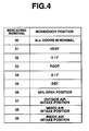
- the POS signals thus produced by the actuators are checked by the control unit 22 and the result of the checking is displayed on the display device 35 by terms of indicating numerals for example, "30" to "39" as shown in the table of Fig. 4.
- the indicating numeral "30" indicates that all doors are in a normal condition
- the indicating numerals "31” to “35” indicate respectively that the mode doors 15, 16 and 17 actuated by the actuator 18c fail to properly set the "VENT", “V/F”, “FOOT”, “D/F” and “DEF” modes
- the indicating numeral "36” indicates that the air mix door 11 actuated by the actuator 18b fails to take the 50% OPEN POSITION
- the indicating numerals "37” to "39” indicate respectively that the intake door 7 actuated by the actuator 18a fails to properly set the "OUTSIDE AIR INTAKE POSITION", "MIXED AIR INTAKE POSITION” and "INSIDE AIR INTAKE POSITION”.
- Fig. 5 there is shown a flowchart which shows first, second, third and fourth general operation steps S1, S2, S3 and S4 which are executed in the control unit 22 for carrying out the STEP-C of the self-diagnosis.
- the control unit 22 checks, at step-S1, the "VENT", “V/F”, “FOOT”, “D/F” and “DEF” modes provided by the mode doors 15, 16 and 17 actuated by the actuator 18c, then checks at step-S2, the 50% OPEN POSITION of the air mix door 11 actuated by the actuator 18b and then checks, at step-S3, the "OUTSIDE AIR INTAKE POSITION", “MIXED AIR INTAKE POSITION” and "INSIDE AIR INTAKE POSITION" of the intake door 7 actuated by the actuator 18a, in order.
- step-S4 When the operations of the step-S1, step-S2 and step-S3 are finshed, the result of the checking is displayed on the display device 35 by using one, or some of the indicating numerals "30" to "39" (step-S4). That is, if the checking finds that some of the modes or door positions fail to take their proper modes or positions, the corresponding indicating numerals are displayed on the display device 35 one after another. Displaying of the result on the display device 35 is carried out with reference to various data memorized in a given memory.
- Fig. 6 there is shown a flowchart which shows in detail the programmed operation steps for checking the positions or diagnosing the operation of the mode doors 15, 16 and 17, that is, the various modes provided by these doors.
- step-S10 from the control unit 22 to the actuator 18c, there is transmitted through the single communication wire 24 a VENT signal which represents proper positions of the mode doors 15, 16 and 17 for the VENT mode.
- the actuator 18c while monitoring the output of the PBR 20, drives the electric motor 19 to move the doors 15, 16 and 17, and issues "0" or "1" signal (viz., POS signal) to the control unit 22. That is, at step-S11, in the control unit 22, a judgment is carried out as to whether "0" signal representing that the doors 15, 16 and 17 have been all set to the proper positions for the VENT mode is received or not. If YES, the operation flow goes to step-S13. While, if NO, the operation flow goes to step-S12 where information on the abnormal VENT mode is memorized.
- step-S13 from the control unit 22 to the actuator 18c, there is transmitted through the communication wire 24 a V/F signal which represents proper positions of the mode doors 15, 16 and 17 for the V/F mode.
- the actuator 18c while monitoring the output of the PBR 20, drives the electric motor 19 to move the doors 15, 16 and 17, and issues "0" or "1" signal to the control unit 22. That is, at step-S14, in the control unit 22, a judgment is carried out as to whether "0" signal representing that the doors 15, 16 and 17 have been all set to the proper positions for the V/F mode is received or not. If YES, the operation flow goes to step-S16. While, if NO, the operation flow goes to step-S15 where information on the abnormal V/F mode is memorized.
- step-S16 from the control unit 22 to the actuator 18c, there is transmitted through the communication wire 24 a FOOT signal which represents proper positions of the mode doors 15, 16 and 17 for the FOOT mode.
- the actuator 18c while monitoring the output of the PBR 20, drives the electric motor 19 to move the doors 15, 16 and 17, and issues "0" or "1" signal to the control unit 22. That is, at step-S17, in the control unit 22, a judgment is carried out as to whether "0" signal representing that the doors 15, 16 and 17 have been all set to the proper positions for the FOOT mode is received or not. If YES, the operation flow goes to step-S19. While, if NO, the operation flow goes to step-S18 where information on the abnormal FOOT mode is memorized.
- step-S19 from the control unit 22 to the actuator 18c, there is transmitted through the communication wire 24 a D/F signal which represents proper positions of the mode doors 15, 16 and 17 for the D/F mode.
- the actuator 18c while monitoring the output of the PBR 20, drives the electric motor 19 to move the doors 15, 16 and 17, and issues "0" or "1" signal to the control unit 22. That is, at step-S20, in the control unit 22, a judgment is carried out as to whether "0" signal representing that the doors 15, 16 and 17 have been all set to the proper positions for the D/F mode is received or not. If YES, the operation flow goes to step-S22. While, if NO, the operation flow goes to step-S21 where information on the abnormal D/F mode is memorized.
- step-S22 from the control unit 22 to the actuator 18c, there is transmitted through the communication wire 24 a DEF signal which represents proper positions of the mode doors 15, 16 and 17 for the DEF mode.
- the actuator 18c while monitoring the output of the PBR 20, drives the electric motor 19 to move the doors 15, 16 and 17, and issues "0" or "1" signal to the control unit 22. That is, at step-S23, in the control unit 22, a judgment is carried out as to whether "0" signal representing that the doors 15, 16 and 17 have been all set to the proper positions for the DEF mode is received or not. If YES, the operation flow goes back to START position of this program. While, if NO, the operation flow goes to step-S24 where information on the abnormal DEF mode is memorized.
- FIG. 7 there is shown a flowchart which shows in detail the programmed operation steps for checking the position or diagnosing the operation of the air mix door 11, that is, the 50% OPEN POSITION of the air mix door 11.
- step-S30 from the control unit 22 to the actuator 18b, there is transmitted through the single communication wire 24 a "50% OPEN POSITION" signal which represents a proper position of the air mix door 11 for the 50% OPEN POSITION.
- the actuator 18b while monitoring the output of the PBR 20, drives the electric motor 19 to move the air mix door 11, and issues "0" or "1" signal (viz., POS signal) to the control unit 22. That is, at step-S31, in the control unit 22, a judgment is carried out as to whether "0" signal representing that the door 11 has been set to the proper position for the 50% OPEN POSITION is received or not. If YES, the operation flow goes back to START position of this program. While, if NO, the operation flow goes to step-S32 where information on the abnormal 50% OPEN POSITION is memorized. The memorized information is displayed on the display device 35 (see Fig. 3) by terms of the indicating numeral "36".
- FIG. 8 there is shown a flowchart which shows in detail the programmed operation steps for checking the various positions or diagnosing the operation of the air intake door 7.
- step-S40 from the control unit 22 to the actuator 18a, there is transmitted through the single communication wire 24 a "OUTSIDE AIR INTAKE POSITION" signal which represents a proper position of the air intake door 7 for the OUTSIDE AIR INTAKE POSITION.
- the actuator 18a while monitoring the output of the PBR 20, drives the electric motor 19 to move the air intake door 7, and issues "0" or "1" signal (viz., POS signal) to the control unit 22. That is, at step-S41, in the control unit 22, a judgment is carried out as to whether "0" signal representing that the air intake door 7 has been set to the proper position for the OUTSIDE AIR INTAKE POSITION is received or not. If YES, the operation flow goes to step-S43. While, if NO, the operation flow goes to step-S2 where information on the abnormal OUTSIDE AIR INTAKE POSITION is memorized.
- step-S43 from the control unit 22 to the actuator 18a, there is transmitted through the communication wire 24 a "MIXED AIR INTAKE POSITION" signal which represents a proper position of the air intake door 7 for the MIXED AIR INTAKE POSITION.
- the actuator 18a while monitoring the output of the PBR 20, drives the electric motor 19 to move the air intake door 7, and issues "0" or "1" signal to the control unit 22. That is, at step-S44, a judgment is carried out as to whether "0" signal representing that the air intake door 7 has been set to the proper position for the MIXED AIR INTAKE POSITION is received or not. If YES, the operation flow goes to step-S46. While, if NO, the operation flow goes to step-S45 where information on the abnormal MIXED AIR INTAKE POSITION is memorized.
- step-S46 from the control unit 22 to the actuator 18a, there is transmitted through the communication wire 24 an "INSIDE AIR INTAKE POSITION" signal which represents a proper position of the air intake door 7 for the INSIDE AIR INTAKE POSITION.
- the actuator 18a while monitoring the output of the PBR 20, drives the electric motor 19 to move the air intake door 7 and issues "0" or "1" signal to the control unit 22. That is, at step-S47, a judgment is carried out as to whether "0" signal representing that the air intake door 7 has been set to the proper position for the INSIDE AIR INTAKE POSITION is received or not. If YES, the operation flow goes to START position of this program. While, if NO, the operation flow goes to step-S48 where information on the abnormal INSIDE AIR INTAKE POSITION is memorized.
- step-S42, step-S45 and/or step-S48 is displayed on the display device 35 (see Fig. 3) by terms of the indicating numeral "37", "38” or "39” (see Fig. 4) one after another if any.
- step-S11, step-S14, step-S17, step-S20 and step-S23 of the program of Fig. 6 the step-S31 of the program of Fig. 7 and the step-S41, step-S44 and step-S47 of the program of fig. 8, the indicating numeral "30" is displayed on the display device 35, indicating that all doors 7, 11, 15, 16 and 17 are in a normal condition.
- information signals (viz., POS signals) on the positions of the corresponding doors 7, 11, 16, 16 and 17 are provided by the actuators 18a, 18b and 18c and they are practically used for checking the positions of the these doors or diagnosing the operation of the doors. That is, in the invention, there is provided a self-diagnosable function by which the positions of the doors 7, 11, 15, 16 and 17 are automatically checked.
Abstract
Description
- The present invention relates in general to automotive air conditioning systems including a plurality of identical actuators for driving control doors, and more particularly to the automotive air conditioning systems of a type having a self-diagnosable function.
- Hitherto, for simplification of harness arrangement and reducing the cost, there have been proposed automotive air conditioning systems of an actuator type in which PBR (potentio-balance-resistor) type actuators are used for driving control doors and all of the actuators are integrally controlled by a control unit (viz., AUTO AMP) by means of a serial communication using a single communication cable. Each actuator has an "IC" installed therein and the PBR detects the current angular position of the control door. In the conventional system of the actuator type, the control unit feeds each actuator with a target position signal which represents a target angular position of the corresponding control door. Upon receiving this signal, the actuator moves the control door to the target angular position with reference to the current position signal issued from the PBR.
- That is, in the conventional system, the current position signal from the PBR is processed by only the actuator. In other words, the current position signal is not fed back to the control unit. Thus, hitherto, in the conventional system of such actuator type, operation check for the control door or doors by means of a self-diagnosis has not been carried out.
- It is therefore an object of the present invention to provide an automotive air conditioning system of an actuator type, which has a self-diagnosable function for checking or diagnosing operation of the control door or doors.
- According to a first aspect of the present invention, there is provided an automotive air conditioning system which comprises a heater/cooler unit having therein a plurality of control doors by which various air flow modes are provided; a plurality of identical actuators for actuating the control doors, each actuator including an electric motor for driving the corresponding control door, a position detector for issuing a given signal representative of the angular position assumed by the corresponding control door, and a control circuit for controlling the electric motor based on the given signal as well as a target position signal applied thereto; a control unit for integrally controlling the actuators by means of a bi-directional serial transmission, the control unit issuing the target position signal to each of the actuators and thereafter judging whether the actuator issues or not a target position accomplishment signal which represents that the corresponding control door has been set to the target position; and a display device for displaying the result of the target position accomplishment judgment carried out by the control unit.
- According to a second aspect of the present invention, there is provided an automotive air conditioning system which includes a heater/cooler unit in which a plurality of control doors are arranged, a plurality of identical actuators each-including an electric motor for driving the corresponding control door, a position detecting means for issuing a voltage signal which represents the current angular position of the corresponding control door and a control circuit for controlling the electric motor based on the voltage signal and a target position signal applied thereto, and a control unit for integrally controlling the identical actuators by means of a bi-directional serial transmission method, the air conditioning system being characterized in that the control unit issues the target position signal to each of the actuators, thereafter judges whether the actuator issues or not a target position accomplishment signal which represents that the corresponding control door has been set to the target position, and thereafter displays the result of the target position accomplishment judgment.
- Other objects and advantages of the present invention will become apparent from the following description when taken in conjunction with the accompanying drawings, in which:
- Fig. 1 is a diagrammatic view of automotive air conditioning system according to the present invention;
- Fig. 2 is a view showing the construction of a communication signal used in the invention;
- Fig. 3 is a front view of a control panel;
- Fig. 4 is a table showing the relationship between indicating numerals and abnormal conditions of various control doors; and
- Fig. 5 is a flowchart showing first, second, third and fourth general operation steps of a self-diagnosis program executed in a control unit;
- Fig. 6 is a flowchart showing the detail of the first general operation step of Fig. 5, which is executed for checking the positions of mode control doors;
- Fig. 7 is a flowchart showing the detail of the second general operation step of Fig. 5, which is executed for checking the position of an air mix door; and
- Fig. 8 is a flowchart showing the detail of the third general operation step of Fig. 5, which is executed for checking the position of an intake door.
- Referring to Fig. 1, there is schematically shown an automotive air conditioning system according to the present invention.
- The system comprises a heater/cooler unit 1 which is conventional in construction.
- The heater/cooler unit 1 generally comprises an
intake unit 2, acooling unit 3 and a heater unit 4. - The
intake unit 2 includes an outside air inlet opening 5 and an inside air inlet opening 6 which are selectively controlled by anair intake door 7. That is, by theair intake door 7, the rated between the outside air amount and inside side amount is controlled. Anelectric blower 8 is arranged at a position downstream of theair intake door 7. Theair intake door 7 is arranged to take for example three positions, which are an "OUTSIDE AIR INTAKE POSITION" wherein the outsideair inlet opening 5 is fully opened (viz., the inside air inlet opening 6 is fully closed), an "INSIDE AIR INTAKE POSITION" wherein the inside air inlet opening 6 is fully opened (viz., the outsideair inlet opening 5 is fully closed) and a "MIXED AIR INTAKE POSITION" wherein both the outside and insideair inlet openings 5 and 6 are partially opened for introducing 80% of inside air and 20% of outside air. - The
cooling unit 3 has anevaporator 9 installed therein. That is, air discharged from theintake unit 2 is cooled by theevaporator 9 and led to the heater unit 4. - The heater unit 4 has at an upstream portion thereof a
heater core 10 in and through which a heated water from a water jacket of an internal combustion engine (not shown) flows. An air mix door 11 is pivotally arranged at a position just upstream of theheater core 10. That is, due to provision of the air mix door 11, there are defined two air flow passages, one being a passage which extends from theevaporator 9 directly to a downstream portion of the heater unit 4 bypassing theheater core 10, and the other being a passage which extends from theevaporator 9 and passes through theheater core 10 before reaching the downstream portion of the heater unit 4. Thus, at the downstream portion, cooled air and heated air are mixed. By changing the angular position of the air mix door 11, the rate between the cooled air amount and the heated air amount at the downstream portion is controlled. With this, the temperature of air blown to a passenger room of an associated motor vehicle is controlled. That is, the mixed air thus adjusted in temperature in the downstream portion of the heater unit 4 is blown to given portions of the passenger room from various discharge openings through respective ducts. - In the illustrated example, the downstream portion of the heater unit 4 has three outlet openings, which are a defroster opening 12 from which conditioned air to be blown to an inner surface of a windshield (not shown) is discharged, a ventilation opening 13 from which conditioned air to be blown to an upper portion of the passenger room is discharged and a foot space opening 14 from which conditioned air to be blown to a lower portion of the passenger room is discharged.
- These three
outlet openings defroster door 15, aventilation door 16 and afoot space door 17, respectively, as shown. In general, thesedoors doors outlet openings defroster opening 12 and the foot space opening 14, and a DEF mode wherein conditioned air is discharged through only the defroster opening 12. - The
control doors actuators intake door 7 is actuated by anintake door actuator 18a, the air mix door 11 is actuated by an airmix door actuator 18b and themode doors 15 to 17 are all actuated by amode door actuator 18c. - The
actuators actuators electric motor 19 for driving the door or doors, aPBR 20 for detecting the current angular position of door or doors, and a control circuit (viz., an integrated circuit including a custom IC) 21a, 21b or 21c. That is, thePBR 20 constitutes a door position detecting means and thecontrol circuit 21 constitutes a control means. ThePBR 20 is a variable resistor whose contact point moves together with a drive shaft (not shown) of theactuator motor 19, the angular position of the corresponding door or doors. As shown, themotor 19 and thePBR 20 are connected to the corresponding control circuit 21a, 21b or 21c. - The control circuit 21a, 21b or 21c has a microcomputer installed therein, which communicates with an after-mentioned
control unit 22 to judge, based on target position signals applied thereto and the voltage output from thePBR 20, whether themotor 19 should be run in normal direction, in reversed direction or stopped. In accordance with this judgment, themotor 19 is operated or stopped. That is, the control circuit 21a, 21b or 21c has three functions, which are a function to communicate with an external element, a function to produce a control signal for themotor 19 and a function to output a drive signal for themotor 19. With these functions of thecontrol circuit 21, eachactuator motor 19. Thecontrol circuit 21 is mounted on a printed circuit board (not shown) installed in theactuator - The
actuators control unit 22 which has a microcomputer installed therein. That is, thecontrol unit 22 constitutes control means. Theactuators control unit 22 through onepower wire 23 and onecommunication wire 24. More specifically, from thecontrol unit 22, there extend only twowires actuators actuator earth wire 25 grounded. Thus, eachactuator power wire 23, onecommunication wire 24 and oneearth wire 25 connected thereto. Thus, the number of the wire harness between thecontrol unit 22 and the threeactuators - That is, in the invention, the bi-directional flow of communication signals between the
control unit 22 and eachactuator communication wire 24. For this communication, a so-called serial transmission is employed That is, in the present invention, eachactuator control unit 22 by means of the serial transmission. - The serial signal used in the serial transmission has such a construction as shown in Fig. 2. Designated by SOM (Start of Message) is a part of 8/3 bits, which represents the starting of transmission. Designated by ADR (Address) is a part of 3 bits, which represents the address of each
actuator actuators control unit 22 at the same time, such ADR signal is used for distinguishing the communication signals. Designated by ENA (Enable) is a part of 1 bit, which represents whether the motor should be run on or not. With this part, the motor can be enforcedly stopped in an abnormal condition. Designated by DATA (Data) is a part of 7 bits, which represents various information for controlling theactuators control unit 22 to theactuators actuators control unit 22, that is, the signal representing whether the door has assumed the target angular position or not. That is, for example, if the door has assumed the target angular position, the POS is represented by "0", while, if the door has not assumed the target position yet, the POS is represented by "1". - As is mentioned hereinabove, the serial signal which is carried by the
communication wire 24 comprises a first communication part which consists of the actuator identification signal (ADR), the motor ON/OFF signal (ENA), the target position signal (DATA) and the abnormal detecting signal (PRTY), and a second communication part which consists of the target position accomplishment signal (POS). The first communication part constitutes the signals which are transmitted from thecontrol unit 22 to eachactuator actuator control unit 22. - In Fig. 3, there is shown a
control panel 26 which has mounted thereon a plurality of switches and a plurality of display devices, which are connected to thecontrol unit 22. As shown, on thecontrol panel 26, there are mounted an A/C (air conditioner) switch 27 which turns on or off a compressor of the air cooling system, afan switch 28 which selects the speed modes of thefan 8, anOFF switch 29 which turns off the entire of the air conditioning system, anAUTO switch 30 which turns on the entire of the air conditioning system and brings the system to an automatic (AUTO) mode, amode switch 31 which selects the air blowing modes,temperature control switches display device 35 for indicating the fan speed and the set temperature, and adisplay device 36 for indicating a selected one of the air blowing modes. TheREC switch 33 and theDEF switch 34 have each an electric lamp. - It is to be noted that the result of the after-mentioned self-diagnosis is displayed on the
display device 35. - The
control panel 26 and thecontrol unit 22 are connected to constitute a controller means. To the controller means, there is connected a battery (not shown). That is, power supply to eachactuator control unit 22 and thepower wire 23. - Although not shown in the drawings, to the
control unit 22, there are connected various sensors which are, for example, an internal air temperature sensor which detects the temperature of air in the passenger room, an external air temperature sensor which detects the temperature of the outside air and a solar radiation quantity sensor which detects the quantity of solar radiation. Processing the information signals from the sensors and theswitches 26 to 34, thecontrol unit 22 issues instruction signals to theactuators single communication wire 24. Upon receiving the instruction signals which represent target angular positions of the doors, eachactuator electric motor 19 in a manner to bring the current door position to the target position, while monitoring the output (which represents the current door position) of thePBR 20. - In addition to the above-mentioned automatic air conditioning functions, the air conditioning system of the present invention has a self-diagnosable function which automatically carries out diagnosis of the
control doors - In the present invention, by using the POS signals (viz., target position accomplishment representing signal) issued from the
actuators - In the self-diagnosis of STEP-C, the three
actuators control unit 22, theactuators control unit 22 and the result of the checking is displayed on thedisplay device 35 by terms of indicating numerals for example, "30" to "39" as shown in the table of Fig. 4. - That is, as is shown in Fig. 4, the indicating numeral "30" indicates that all doors are in a normal condition, the indicating numerals "31" to "35" indicate respectively that the
mode doors actuator 18c fail to properly set the "VENT", "V/F", "FOOT", "D/F" and "DEF" modes, the indicating numeral "36" indicates that the air mix door 11 actuated by theactuator 18b fails to take the 50% OPEN POSITION and the indicating numerals "37" to "39" indicate respectively that theintake door 7 actuated by theactuator 18a fails to properly set the "OUTSIDE AIR INTAKE POSITION", "MIXED AIR INTAKE POSITION" and "INSIDE AIR INTAKE POSITION". - In Fig. 5, there is shown a flowchart which shows first, second, third and fourth general operation steps S1, S2, S3 and S4 which are executed in the
control unit 22 for carrying out the STEP-C of the self-diagnosis. - When execution of the self-diagnosis program of the above-mentioned STEP-C is started, the
control unit 22 checks, at step-S1, the "VENT", "V/F", "FOOT", "D/F" and "DEF" modes provided by themode doors actuator 18c, then checks at step-S2, the 50% OPEN POSITION of the air mix door 11 actuated by theactuator 18b and then checks, at step-S3, the "OUTSIDE AIR INTAKE POSITION", "MIXED AIR INTAKE POSITION" and "INSIDE AIR INTAKE POSITION" of theintake door 7 actuated by theactuator 18a, in order. When the operations of the step-S1, step-S2 and step-S3 are finshed, the result of the checking is displayed on thedisplay device 35 by using one, or some of the indicating numerals "30" to "39" (step-S4). That is, if the checking finds that some of the modes or door positions fail to take their proper modes or positions, the corresponding indicating numerals are displayed on thedisplay device 35 one after another. Displaying of the result on thedisplay device 35 is carried out with reference to various data memorized in a given memory. - In Fig. 6, there is shown a flowchart which shows in detail the programmed operation steps for checking the positions or diagnosing the operation of the
mode doors - At step-S10, from the
control unit 22 to theactuator 18c, there is transmitted through the single communication wire 24 a VENT signal which represents proper positions of themode doors actuator 18c, while monitoring the output of thePBR 20, drives theelectric motor 19 to move thedoors control unit 22. That is, at step-S11, in thecontrol unit 22, a judgment is carried out as to whether "0" signal representing that thedoors - At step-S13, from the
control unit 22 to theactuator 18c, there is transmitted through the communication wire 24 a V/F signal which represents proper positions of themode doors actuator 18c, while monitoring the output of thePBR 20, drives theelectric motor 19 to move thedoors control unit 22. That is, at step-S14, in thecontrol unit 22, a judgment is carried out as to whether "0" signal representing that thedoors - At step-S16, from the
control unit 22 to theactuator 18c, there is transmitted through the communication wire 24 a FOOT signal which represents proper positions of themode doors actuator 18c, while monitoring the output of thePBR 20, drives theelectric motor 19 to move thedoors control unit 22. That is, at step-S17, in thecontrol unit 22, a judgment is carried out as to whether "0" signal representing that thedoors - At step-S19, from the
control unit 22 to theactuator 18c, there is transmitted through the communication wire 24 a D/F signal which represents proper positions of themode doors actuator 18c, while monitoring the output of thePBR 20, drives theelectric motor 19 to move thedoors control unit 22. That is, at step-S20, in thecontrol unit 22, a judgment is carried out as to whether "0" signal representing that thedoors - At step-S22, from the
control unit 22 to theactuator 18c, there is transmitted through the communication wire 24 a DEF signal which represents proper positions of themode doors actuator 18c, while monitoring the output of thePBR 20, drives theelectric motor 19 to move thedoors control unit 22. That is, at step-S23, in thecontrol unit 22, a judgment is carried out as to whether "0" signal representing that thedoors - Memorized information at step-S12, step-S15, step-S18, step-S21 and/or step-S24 is displayed on the display device 35 (see Fig. 3) by terms of the indicating numeral "31", "32", "33", "34" or "35" (see Fig. 4) one after another if any.
- In Fig. 7, there is shown a flowchart which shows in detail the programmed operation steps for checking the position or diagnosing the operation of the air mix door 11, that is, the 50% OPEN POSITION of the air mix door 11.
- At step-S30, from the
control unit 22 to theactuator 18b, there is transmitted through the single communication wire 24 a "50% OPEN POSITION" signal which represents a proper position of the air mix door 11 for the 50% OPEN POSITION. Upon this, theactuator 18b, while monitoring the output of thePBR 20, drives theelectric motor 19 to move the air mix door 11, and issues "0" or "1" signal (viz., POS signal) to thecontrol unit 22. That is, at step-S31, in thecontrol unit 22, a judgment is carried out as to whether "0" signal representing that the door 11 has been set to the proper position for the 50% OPEN POSITION is received or not. If YES, the operation flow goes back to START position of this program. While, if NO, the operation flow goes to step-S32 where information on the abnormal 50% OPEN POSITION is memorized. The memorized information is displayed on the display device 35 (see Fig. 3) by terms of the indicating numeral "36". - In Fig. 8, there is shown a flowchart which shows in detail the programmed operation steps for checking the various positions or diagnosing the operation of the
air intake door 7. - At step-S40, from the
control unit 22 to theactuator 18a, there is transmitted through the single communication wire 24 a "OUTSIDE AIR INTAKE POSITION" signal which represents a proper position of theair intake door 7 for the OUTSIDE AIR INTAKE POSITION. Upon this, theactuator 18a, while monitoring the output of thePBR 20, drives theelectric motor 19 to move theair intake door 7, and issues "0" or "1" signal (viz., POS signal) to thecontrol unit 22. That is, at step-S41, in thecontrol unit 22, a judgment is carried out as to whether "0" signal representing that theair intake door 7 has been set to the proper position for the OUTSIDE AIR INTAKE POSITION is received or not. If YES, the operation flow goes to step-S43. While, if NO, the operation flow goes to step-S2 where information on the abnormal OUTSIDE AIR INTAKE POSITION is memorized. - At step-S43, from the
control unit 22 to theactuator 18a, there is transmitted through the communication wire 24 a "MIXED AIR INTAKE POSITION" signal which represents a proper position of theair intake door 7 for the MIXED AIR INTAKE POSITION. Upon this, theactuator 18a, while monitoring the output of thePBR 20, drives theelectric motor 19 to move theair intake door 7, and issues "0" or "1" signal to thecontrol unit 22. That is, at step-S44, a judgment is carried out as to whether "0" signal representing that theair intake door 7 has been set to the proper position for the MIXED AIR INTAKE POSITION is received or not. If YES, the operation flow goes to step-S46. While, if NO, the operation flow goes to step-S45 where information on the abnormal MIXED AIR INTAKE POSITION is memorized. - At step-S46, from the
control unit 22 to theactuator 18a, there is transmitted through thecommunication wire 24 an "INSIDE AIR INTAKE POSITION" signal which represents a proper position of theair intake door 7 for the INSIDE AIR INTAKE POSITION. Upon this, theactuator 18a, while monitoring the output of thePBR 20, drives theelectric motor 19 to move theair intake door 7 and issues "0" or "1" signal to thecontrol unit 22. That is, at step-S47, a judgment is carried out as to whether "0" signal representing that theair intake door 7 has been set to the proper position for the INSIDE AIR INTAKE POSITION is received or not. If YES, the operation flow goes to START position of this program. While, if NO, the operation flow goes to step-S48 where information on the abnormal INSIDE AIR INTAKE POSITION is memorized. - Memorized information at step-S42, step-S45 and/or step-S48 is displayed on the display device 35 (see Fig. 3) by terms of the indicating numeral "37", "38" or "39" (see Fig. 4) one after another if any.
- If YES is answered throughout the step-S11, step-S14, step-S17, step-S20 and step-S23 of the program of Fig. 6, the step-S31 of the program of Fig. 7 and the step-S41, step-S44 and step-S47 of the program of fig. 8, the indicating numeral "30" is displayed on the
display device 35, indicating that alldoors - As has been described hereinabove, in the present invention, information signals (viz., POS signals) on the positions of the
corresponding doors actuators doors
Claims (10)
- An automotive air conditioning system comprising:a heater/cooler unit having therein a plurality of control doors by which various air flow modes are provided;a plurality of identical actuators for actuating said control doors, each actuator including an electric motor for driving the corresponding control door, a position detector for issuing a current position signal representative of a current angular position assumed by the corresponding control door, and a control circuit for controlling said electric motor based on said current position signal as well as a target position signal applied thereto;a control unit for integrally controlling said actuators by means of a bi-directional serial transmission method, said control unit issuing the target position signal to each of said actuators and thereafter judging whether the actuator issues or not a target position accomplishment signal which represents that the corresponding control door has been set to the target position; anda display device for displaying the result of the target position accomplishment judgment carried out by said control unit.
- An automotive conditioning system as claimed in Claim 1, in which all of said actuators are connected to said control unit by one communication wire through which said bi-directional serial communication is carried out.
- An automotive air conditioning system as claimed in Claim 2, in which a serial signal transmitted between said control unit and each actuator includes a SOM part of 8/3 bits which represents starting of transmission, an ADR part of 3 bits which represents the address of each actuator, an ENA part of 1 bit which represents whether the corresponding electric motor should be run or not, a DATA part of 7 bits which represents various information for controlling the actuators, a PRTY part of 1 bit which represents odd parity for the ADR, ENA and DATA parts, and a POS part of 1 bit which represents whether the corresponding door has assumed the target angular position or not.
- An automotive air conditioning system as claimed in Claim 3, in which the SOM, ADR, ENA, DATA and PRTY parts carry information signals which are to be transmitted from said control unit to each actuator, and in which the POS part carries an information signal which is to be transmitted from each actuator to said control unit.
- An automotive air conditioning system as claimed in Claim 2, in which said control doors are classified into first, second and third groups, said first group including an air intake door by which the rate between outside air intake amount and inside air intake amount is controlled, said second group including an air mix door by which the rate between the amount of air which flows directly from an evaporator to an air mix chamber and the amount of air which flows from said evaporation to said air mix chamber through a heater core is controlled, said third group including a plurality of mode doors by which various modes are provided.
- An automotive air conditioning system as claimed in Claim 5, in which said actuators include first, second and third actuators which are incorporated with said first, second and third groups of control doors respectively.
- An automotive air conditioning system as claimed in Claim 1, in which said display device displays the result of the target position accomplishment judgment by terms of at least one indicating numeral.
- An automotive air conditioning system as claimed in Claim 1, said control unit memorizes the result of the target position accomplishment judgment when the selected actuator fails to issue the target position accomplishment signal.
- An automotive air conditioning system as claimed in Claim 1, in which the information possessed by said target position accomplishment signal is represented by "0".
- An automotive air conditioning system including a heater/cooler unit in which a plurality of control doors are arranged, a plurality of identical actuators each including an electric motor for driving the corresponding control door, a position detecting means for issuing a voltage signal which represents the current angular position of the corresponding control door and a control circuit for controlling the electric motor based on the voltage signal and a target position signal applied thereto, and a control unit for integrally controlling the identical actuators by means of a bi-directional serial transmission method, which is characterized in that:
said control unit issues the target position signal to each of said actuators, thereafter judges whether the actuator issues or not a target position accomplishment signal which represents that the corresponding control door has been set to the target position, and thereafter displays the result of the target position accomplishment judgment.
Applications Claiming Priority (3)
| Application Number | Priority Date | Filing Date | Title |
|---|---|---|---|
| JP256588/95 | 1995-10-03 | ||
| JP25658895 | 1995-10-03 | ||
| JP25658895A JP3601886B2 (en) | 1995-10-03 | 1995-10-03 | Automotive air conditioning system |
Publications (3)
| Publication Number | Publication Date |
|---|---|
| EP0771679A2 true EP0771679A2 (en) | 1997-05-07 |
| EP0771679A3 EP0771679A3 (en) | 1998-08-12 |
| EP0771679B1 EP0771679B1 (en) | 2001-06-13 |
Family
ID=17294721
Family Applications (1)
| Application Number | Title | Priority Date | Filing Date |
|---|---|---|---|
| EP96115849A Expired - Lifetime EP0771679B1 (en) | 1995-10-03 | 1996-10-02 | Automotive air conditioning system with self-diagnosable function |
Country Status (4)
| Country | Link |
|---|---|
| EP (1) | EP0771679B1 (en) |
| JP (1) | JP3601886B2 (en) |
| KR (1) | KR100187733B1 (en) |
| DE (1) | DE69613315T2 (en) |
Cited By (7)
| Publication number | Priority date | Publication date | Assignee | Title |
|---|---|---|---|---|
| WO1998051918A1 (en) * | 1997-05-13 | 1998-11-19 | Mannesmann Vdo Ag | Load adjusting device |
| EP0838357A3 (en) * | 1996-10-25 | 1999-06-23 | Calsonic Corporation | Vehicle air-conditioning system |
| EP1078786A2 (en) * | 1999-08-20 | 2001-02-28 | Denso Corporation | Vehicle air-conditioning system with arrangement of electrical member |
| EP0769398B1 (en) * | 1995-10-19 | 2001-04-11 | Calsonic Kansei Corporation | Control system of automotive air conditioning device |
| WO2001044632A3 (en) * | 1999-12-14 | 2001-12-27 | Bosch Gmbh Robert | Control valve |
| EP1480094A3 (en) * | 2003-05-22 | 2008-02-13 | Calsonic Kansei Corporation | Servomotor controller |
| JP2018513054A (en) * | 2015-06-18 | 2018-05-24 | デンソー インターナショナル アメリカ インコーポレーテッド | Blower motor diagnosis method and blower unit |
Families Citing this family (2)
| Publication number | Priority date | Publication date | Assignee | Title |
|---|---|---|---|---|
| WO2002062185A1 (en) * | 2001-02-08 | 2002-08-15 | Acrobio Technology Co., Ltd. | Heat exchanging system |
| KR101193374B1 (en) | 2006-07-28 | 2012-10-19 | 한라공조주식회사 | Method for testing action of air conditioning control device |
Citations (6)
| Publication number | Priority date | Publication date | Assignee | Title |
|---|---|---|---|---|
| US4688389A (en) * | 1985-03-18 | 1987-08-25 | Diesel Kiki Kabushiki Kaisha | Automotive air-conditioning system |
| US4712173A (en) * | 1984-10-01 | 1987-12-08 | Yamatake Honeywell | Multicontrol process control system |
| US4819715A (en) * | 1983-09-14 | 1989-04-11 | Nissan Shatai Company, Limited | Automatic air conditioning system for an automotive vehicle |
| JPH01190520A (en) * | 1988-01-27 | 1989-07-31 | Diesel Kiki Co Ltd | Vehicle air-condition control device |
| US5440486A (en) * | 1993-06-01 | 1995-08-08 | Chrysler Corporation | Predictive electric motor positioning device, normal operating system therefor |
| GB2287622A (en) * | 1994-03-17 | 1995-09-20 | Nissan Motor | Multiplex serial data communication circuit network for a motor control system |
-
1995
- 1995-10-03 JP JP25658895A patent/JP3601886B2/en not_active Expired - Fee Related
-
1996
- 1996-10-02 KR KR1019960043648A patent/KR100187733B1/en not_active IP Right Cessation
- 1996-10-02 EP EP96115849A patent/EP0771679B1/en not_active Expired - Lifetime
- 1996-10-02 DE DE69613315T patent/DE69613315T2/en not_active Expired - Lifetime
Patent Citations (6)
| Publication number | Priority date | Publication date | Assignee | Title |
|---|---|---|---|---|
| US4819715A (en) * | 1983-09-14 | 1989-04-11 | Nissan Shatai Company, Limited | Automatic air conditioning system for an automotive vehicle |
| US4712173A (en) * | 1984-10-01 | 1987-12-08 | Yamatake Honeywell | Multicontrol process control system |
| US4688389A (en) * | 1985-03-18 | 1987-08-25 | Diesel Kiki Kabushiki Kaisha | Automotive air-conditioning system |
| JPH01190520A (en) * | 1988-01-27 | 1989-07-31 | Diesel Kiki Co Ltd | Vehicle air-condition control device |
| US5440486A (en) * | 1993-06-01 | 1995-08-08 | Chrysler Corporation | Predictive electric motor positioning device, normal operating system therefor |
| GB2287622A (en) * | 1994-03-17 | 1995-09-20 | Nissan Motor | Multiplex serial data communication circuit network for a motor control system |
Non-Patent Citations (1)
| Title |
|---|
| PATENT ABSTRACTS OF JAPAN vol. 13, no. 484 (M-886), 2 November 1989 & JP 01 190520 A (DIESEL KIKI CO LTD), 31 July 1989, * |
Cited By (13)
| Publication number | Priority date | Publication date | Assignee | Title |
|---|---|---|---|---|
| EP0769398B1 (en) * | 1995-10-19 | 2001-04-11 | Calsonic Kansei Corporation | Control system of automotive air conditioning device |
| EP1304243A2 (en) * | 1996-10-25 | 2003-04-23 | Calsonic Kansei Corporation | Vehicle air-conditioning system |
| EP0838357A3 (en) * | 1996-10-25 | 1999-06-23 | Calsonic Corporation | Vehicle air-conditioning system |
| EP1300268A1 (en) * | 1996-10-25 | 2003-04-09 | Calsonic Kansei Corporation | Vehicle air-conditioning system |
| EP1304243A3 (en) * | 1996-10-25 | 2003-11-12 | Calsonic Kansei Corporation | Vehicle air-conditioning system |
| WO1998051918A1 (en) * | 1997-05-13 | 1998-11-19 | Mannesmann Vdo Ag | Load adjusting device |
| EP1078786A2 (en) * | 1999-08-20 | 2001-02-28 | Denso Corporation | Vehicle air-conditioning system with arrangement of electrical member |
| EP1078786A3 (en) * | 1999-08-20 | 2004-01-02 | Denso Corporation | Vehicle air-conditioning system with arrangement of electrical member |
| WO2001044632A3 (en) * | 1999-12-14 | 2001-12-27 | Bosch Gmbh Robert | Control valve |
| US6705586B2 (en) | 1999-12-14 | 2004-03-16 | Robert Bosch Gmbh | Control valve |
| EP1480094A3 (en) * | 2003-05-22 | 2008-02-13 | Calsonic Kansei Corporation | Servomotor controller |
| EP1914611A1 (en) * | 2003-05-22 | 2008-04-23 | Calsonic Kansei Corporation | Servomotor controller |
| JP2018513054A (en) * | 2015-06-18 | 2018-05-24 | デンソー インターナショナル アメリカ インコーポレーテッド | Blower motor diagnosis method and blower unit |
Also Published As
| Publication number | Publication date |
|---|---|
| JP3601886B2 (en) | 2004-12-15 |
| KR970020520A (en) | 1997-05-28 |
| DE69613315D1 (en) | 2001-07-19 |
| KR100187733B1 (en) | 1999-06-01 |
| EP0771679B1 (en) | 2001-06-13 |
| EP0771679A3 (en) | 1998-08-12 |
| JPH0999729A (en) | 1997-04-15 |
| DE69613315T2 (en) | 2001-10-18 |
Similar Documents
| Publication | Publication Date | Title |
|---|---|---|
| EP1265764B1 (en) | Heating/ventilating/air conditioning module for vehicle | |
| US6640890B1 (en) | Multiple zone automatic HVAC control system and method | |
| US6501239B2 (en) | Air conditioner for vehicle | |
| JP6492812B2 (en) | Actuator control system | |
| US5729989A (en) | Electronic climate control system for automotive vehicles | |
| EP0771679B1 (en) | Automotive air conditioning system with self-diagnosable function | |
| US4688389A (en) | Automotive air-conditioning system | |
| US4827730A (en) | Troubleshooting apparatus for automobile air-conditioning system | |
| JPS6061324A (en) | Automatic controlling air conditioner | |
| US4488409A (en) | Trouble diagnosing apparatus for an automobile air conditioner | |
| JP2006103413A (en) | Electric actuator system | |
| JP3809876B2 (en) | Door actuator device for vehicle air conditioner system | |
| JP3661268B2 (en) | Fault diagnosis device | |
| JP3585304B2 (en) | Automotive air conditioning system | |
| JP3604244B2 (en) | Automotive air conditioners | |
| JP2006273267A (en) | Actuator control device | |
| JP4483534B2 (en) | Air conditioner for vehicles | |
| JP4023291B2 (en) | Air conditioning control member drive mechanism | |
| KR20180041997A (en) | System for controlling air conditioner of vehicle sensing passenger and the method thereof | |
| JP3783982B2 (en) | Communication processing device for automatic temperature control of vehicle air conditioner system | |
| JPH08332832A (en) | Air conditioning system for automobile | |
| JPH08332833A (en) | Air conditioning system for automobile | |
| JP3571854B2 (en) | Air conditioning control device for vehicle air conditioning system | |
| JP2006273007A (en) | Circuit abnormality diagnosis device | |
| KR20100010145A (en) | Apparatus and method for controlling door actuator of air conditioning system in automobile |
Legal Events
| Date | Code | Title | Description |
|---|---|---|---|
| PUAI | Public reference made under article 153(3) epc to a published international application that has entered the european phase |
Free format text: ORIGINAL CODE: 0009012 |
|
| 17P | Request for examination filed |
Effective date: 19961002 |
|
| AK | Designated contracting states |
Kind code of ref document: A2 Designated state(s): DE FR GB |
|
| PUAL | Search report despatched |
Free format text: ORIGINAL CODE: 0009013 |
|
| AK | Designated contracting states |
Kind code of ref document: A3 Designated state(s): DE FR GB |
|
| 17Q | First examination report despatched |
Effective date: 19981130 |
|
| GRAG | Despatch of communication of intention to grant |
Free format text: ORIGINAL CODE: EPIDOS AGRA |
|
| GRAG | Despatch of communication of intention to grant |
Free format text: ORIGINAL CODE: EPIDOS AGRA |
|
| GRAH | Despatch of communication of intention to grant a patent |
Free format text: ORIGINAL CODE: EPIDOS IGRA |
|
| RAP1 | Party data changed (applicant data changed or rights of an application transferred) |
Owner name: CALSONIC KANSEI CORPORATION |
|
| GRAH | Despatch of communication of intention to grant a patent |
Free format text: ORIGINAL CODE: EPIDOS IGRA |
|
| GRAA | (expected) grant |
Free format text: ORIGINAL CODE: 0009210 |
|
| AK | Designated contracting states |
Kind code of ref document: B1 Designated state(s): DE FR GB |
|
| REF | Corresponds to: |
Ref document number: 69613315 Country of ref document: DE Date of ref document: 20010719 |
|
| ET | Fr: translation filed | ||
| REG | Reference to a national code |
Ref country code: GB Ref legal event code: IF02 |
|
| PLBE | No opposition filed within time limit |
Free format text: ORIGINAL CODE: 0009261 |
|
| STAA | Information on the status of an ep patent application or granted ep patent |
Free format text: STATUS: NO OPPOSITION FILED WITHIN TIME LIMIT |
|
| 26N | No opposition filed | ||
| PGFP | Annual fee paid to national office [announced via postgrant information from national office to epo] |
Ref country code: GB Payment date: 20120926 Year of fee payment: 17 |
|
| PGFP | Annual fee paid to national office [announced via postgrant information from national office to epo] |
Ref country code: FR Payment date: 20121018 Year of fee payment: 17 Ref country code: DE Payment date: 20120927 Year of fee payment: 17 |
|
| GBPC | Gb: european patent ceased through non-payment of renewal fee |
Effective date: 20131002 |
|
| REG | Reference to a national code |
Ref country code: DE Ref legal event code: R119 Ref document number: 69613315 Country of ref document: DE Effective date: 20140501 |
|
| PG25 | Lapsed in a contracting state [announced via postgrant information from national office to epo] |
Ref country code: GB Free format text: LAPSE BECAUSE OF NON-PAYMENT OF DUE FEES Effective date: 20131002 |
|
| REG | Reference to a national code |
Ref country code: FR Ref legal event code: ST Effective date: 20140630 |
|
| PG25 | Lapsed in a contracting state [announced via postgrant information from national office to epo] |
Ref country code: FR Free format text: LAPSE BECAUSE OF NON-PAYMENT OF DUE FEES Effective date: 20131031 Ref country code: DE Free format text: LAPSE BECAUSE OF NON-PAYMENT OF DUE FEES Effective date: 20140501 |