EP0771634A2 - Shutoff valve and filter in thermoplastic material supply system - Google Patents
Shutoff valve and filter in thermoplastic material supply system Download PDFInfo
- Publication number
- EP0771634A2 EP0771634A2 EP19960116140 EP96116140A EP0771634A2 EP 0771634 A2 EP0771634 A2 EP 0771634A2 EP 19960116140 EP19960116140 EP 19960116140 EP 96116140 A EP96116140 A EP 96116140A EP 0771634 A2 EP0771634 A2 EP 0771634A2
- Authority
- EP
- European Patent Office
- Prior art keywords
- valve
- filter
- reservoir
- assembly
- thermoplastic material
- Prior art date
- Legal status (The legal status is an assumption and is not a legal conclusion. Google has not performed a legal analysis and makes no representation as to the accuracy of the status listed.)
- Withdrawn
Links
Images


Classifications
-
- B—PERFORMING OPERATIONS; TRANSPORTING
- B29—WORKING OF PLASTICS; WORKING OF SUBSTANCES IN A PLASTIC STATE IN GENERAL
- B29B—PREPARATION OR PRETREATMENT OF THE MATERIAL TO BE SHAPED; MAKING GRANULES OR PREFORMS; RECOVERY OF PLASTICS OR OTHER CONSTITUENTS OF WASTE MATERIAL CONTAINING PLASTICS
- B29B13/00—Conditioning or physical treatment of the material to be shaped
- B29B13/02—Conditioning or physical treatment of the material to be shaped by heating
- B29B13/022—Melting the material to be shaped
-
- B—PERFORMING OPERATIONS; TRANSPORTING
- B05—SPRAYING OR ATOMISING IN GENERAL; APPLYING FLUENT MATERIALS TO SURFACES, IN GENERAL
- B05C—APPARATUS FOR APPLYING FLUENT MATERIALS TO SURFACES, IN GENERAL
- B05C11/00—Component parts, details or accessories not specifically provided for in groups B05C1/00 - B05C9/00
- B05C11/10—Storage, supply or control of liquid or other fluent material; Recovery of excess liquid or other fluent material
- B05C11/1042—Storage, supply or control of liquid or other fluent material; Recovery of excess liquid or other fluent material provided with means for heating or cooling the liquid or other fluent material in the supplying means upstream of the applying apparatus
-
- Y—GENERAL TAGGING OF NEW TECHNOLOGICAL DEVELOPMENTS; GENERAL TAGGING OF CROSS-SECTIONAL TECHNOLOGIES SPANNING OVER SEVERAL SECTIONS OF THE IPC; TECHNICAL SUBJECTS COVERED BY FORMER USPC CROSS-REFERENCE ART COLLECTIONS [XRACs] AND DIGESTS
- Y10—TECHNICAL SUBJECTS COVERED BY FORMER USPC
- Y10T—TECHNICAL SUBJECTS COVERED BY FORMER US CLASSIFICATION
- Y10T137/00—Fluid handling
- Y10T137/794—With means for separating solid material from the fluid
- Y10T137/8122—Planar strainer normal to flow path
Abstract
Description
- This invention relates to apparatus for melting and supplying thermoplastic materials to a dispensing system.
- Thermoplastic materials or so-called "hot melt" materials have been used for many years for various purposes, including as adhesives in the manufacturing of products such as disposable diapers and in the manufacturing of packaging. Historically, the thermoplastic material was converted from a solid to a molten state in a tank having heated walls. The melted material was maintained in the molten state in the tank in sufficient volume to supply one or more applicators or dispensers. If the job or application required a substantial volume of hot melt material, a substantially large volume of material was required to be maintained in the molten or melted state, necessitating a long warm up or start up time for the apparatus, as well as prolonged exposure of at least some of the molten material to heat and/or to oxygen.
- To avoid these problems, so-called grid-type hot melt supply systems were developed in which the solid thermoplastic material was stored in a hopper and melted upon the top of a heated grid located at the bottom of the hopper. The melted material then passed through holes in the grid into a relatively small holding reservoir from which the molten material was supplied by a pump beneath the reservoir to a dispenser. Grid-type supply systems have been capable of melting and supplying thermoplastic material at a very high rate, and the molten material is not maintained in a molten state for prolonged periods of time to char, oxidize, or otherwise degrade. A typical grid type hot melt supply system is disclosed in U.S. Pat. No. 3,946,645.
- These grid-type hot melt supply systems have typically comprised a reservoir with a heated grid mounted on top of the reservoir. A hopper for receiving the solid thermoplastic material was mounted atop the heated grid. Mounted beneath the reservoir was at least one pump for pumping the molten thermoplastic material through one or more supply hoses which were connected to the pump. A flow passage was provided from the reservoir outlet to the pump inlet.
- One problem with these hot melt supply systems has been that, in use, various extraneous objects or impurities could enter the hopper. Larger objects and impurities were prevented from passing through the openings in the grid, but smaller objects could pass through the grid and eventually reach the pump, resulting in periodic failure or clogging of the pump. If the pump failed or became clogged, it had to be removed and repaired or replaced.
- To avoid draining the system of the thermoplastic material if the pump needed to be removed, a manually operated gate-type valve was sometimes located in the molten thermoplastic flow path between the reservoir outlet and the pump. An example of such a valve is shown in U.S. Pat. No. 4,666,066. This valve made it possible stop the flow of molten thermoplastic material to the pump whenever the pump needed to be removed, and the pump could then be removed without the necessity of first draining the entire reservoir of molten thermoplastic material. Another example of a flow shutoff valve that could be used to shut off the flow of material to the pump is shown in U.S. Pat. No. 4,667,850. Removal of the pump has still been difficult because the motor for driving the pump had to be disconnected from the pump in the course of removing the pump from the system, and to facilitate quick disconnection of the driving motor from the pump, U.S. Pat. No. 4,666,066 also discloses the provision of a motor mount to enable the pump to be more quickly removed from the system.
- Although the presence of the gate-type valve and the quick disconnection of the pump motor make it easier to remove the pump to change or to repair the pump, servicing the pump should be performed as infrequently as possible, since it requires that the system be shutdown, and system shutdown should be avoided, since it allows the material in the hopper and the reservoir to solidify. After the material solidifies, it must thereafter be remelted, resulting in loss of system efficiency and capability. The removal and replacement of the pump still results in long downtimes of the supply system, and substantial quantities of wasted thermoplastic material.
- Pump servicing can be reduced by providing a filter in the material flow path between the reservoir and the pump, but such a filter must be periodically removed for cleaning, and the flow path should be closed when the filter is removed to prevent the inadvertent leakage of molten thermoplastic material from the flow path.
- The present invention overcomes the difficulties of the prior art by providing a flow shutoff valve which is combined with a removable filter. The combined valve and filter assembly can be closed to conveniently shut off the flow of molten thermoplastic material to the pump and can be opened to allow the material to be filtered to prevent undesirable foreign objects or debris from reaching the pump. The present invention provides a flow shutoff valve for a grid-type molten thermoplastic material supply system which provides an easy and convenient shutoff of the flow of molten material to the pump, so that the pump can be more easily removed for repair and replacement. In addition, the filter, which is combined with the valve, prevents various extraneous objects or impurities from reaching the pump, so that pump servicing is performed less frequently.
- The valve and filter assembly of the present invention also provides for easy removal of the filter for cleaning. The valve includes an interlocking mechanism that prevents the filter from being removed unless the valve is closed, so that molten thermoplastic material will not be inadvertently spilled. This interlocking mechanism assures that the filter will only be removed when there is no flow of molten thermoplastic material to the pump, and prevents inadvertent removal of the filter while the valve is open.
- These and other advantages are provided by the present invention of a system for supplying molten thermoplastic material to a dispenser. The system comprises a hopper for storing the thermoplastic material. A heating grid is associated with the hopper for heating and melting the thermoplastic material. A reservoir block receives melted material from the grid. The reservoir block includes a reservoir into which the melted material flows from the grid. A manifold and pump assembly is connected to the reservoir block for receiving material from the reservoir and pumping the material to a dispenser. A valve and filter assembly is mounted in the reservoir block. The valve and filter assembly includes a valve member capable of moving between an open position and a closed position for blocking the flow the material through the reservoir block, and includes a filter member for filtering material, the filter being removable to clean the filter.
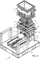
- FIG. 1 is a perspective front view of the thermoplastic supply system of the present invention, with the support structure omitted.
- FIG. 2 is an exploded perspective front view of the thermoplastic supply system of FIG. 1.
- FIG. 3 is another exploded perspective view of the thermoplastic supply system of FIGS. 1 and 2 taken from the rear of the system with the support structure included, but with the drive assembly removed.
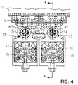
- FIG. 4 is a front elevational view of a portion of the thermoplastic supply system of FIGS. 1-3 showing the reservoir block.
- FIG. 5 is a side sectional view taken along
line 5―5 of FIG. 4. - FIG. 6 is a side sectional view taken along
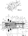
line 6―6 of FIG. 5. - FIG. 7 is a detail of the valve assembly of FIG. 5 to a larger scale.
- FIG. 8 is perspective view of the valve assembly of FIG. 7 removed from the reservoir block.
- FIG. 9 is an exploded perspective view of the valve assembly of FIG. 8.
- Referring more particularly to the drawings and initially to FIGS. 1 and 2, there is shown the thermoplastic
material supply system 10 of the present invention. The system is used for various purposes, such as to apply hot melt adhesive in a manufacturing line for specific products, such as for disposable diapers. A manufacturing line of disposable diapers may include, by way of example, a station for applying adhesive to the left and right leg elastic, to the waist elastic attachment and to the cuff elastic. Thesupply system 10 is connected to dispensers or applicators located at the manufacturing line by means of heated supply hoses. Various types of dispensers or applicators may be in the manufacturing line to apply the material, and these dispensers are not part of this invention. Thesupply system 10 is used to heat the solid thermoplastic material and to supply the molten material through various numbers of supply hoses to the dispensers. - The
system 10 comprises a hopper assembly 11 for receiving and storing a supply of solid thermoplastic material. The hopper assembly 11 comprises one ormore hopper units 12. The top of the hopper assembly 11 is open, allowing solid thermoplastic material to be placed in the hopper assembly. The bottom of the hopper assembly 11 is also open providing an outlet, and aheating grid 13 is mounted within the outlet of the hopper assembly. Theheating grid 13 is used to melt the solid thermoplastic material in the hopper. Although thegrid 13 is not in the form of a grid in the conventional definition of the term, since it is in the form of a pyramid-shaped cast block, it replaces the heating grids used in prior art systems, so it is called a "grid." The hopper assembly 11 is supported on areservoir assembly 14 located below the hopper assembly 11, with aceramic isolator 15 mounted therebetween. The reservoir assembly includes ablock 16, the upper surface of which forms areservoir 17 which receives a supply of melted material from the hopper assembly 11. Inside thereservoir block 16 are a pair of passageways through which the molten thermoplastic flows from the reservoir to a pair ofmanifold assemblies 18 positioned beneath the reservoir block. (Only one of the manifold assemblies is shown in FIGS. 1 and 2.) Eachmanifold assembly 18 includes amanifold block 19. Themanifold block 19 may include an internal heater or may be heated by means of a separate attachedheater plate 20. Thereservoir assembly 14 includes a pair offlow shutoff valves 21 mounted in thereservoir block 16 each of which allows the flow of molten material through one of the passageways to one of the manifold assemblies to be shut off. Each of theflow shutoff valves 21 also includes a filter or protection screen to prevent extraneous particulate material from reaching the pump. Themanifold assemblies 18 are inserted into a manifold harness or saddle 22 which is suspended from the bottom of thereservoir block 16. The manifold assembly is inserted into the harness and held securely against the reservoir block by means of a screw jack assembly. Apump 23 is adapted to be inserted into each of themanifold assemblies 18. Each of thepumps 23 is connected to adrive assembly 24, and the pump and the drive assembly are mounted on a horizontallymoveable carriage 25 which moves on acarriage support 26. Each of themanifold assemblies 18 includes a connection for one or more supply hoses (not shown). The molten thermoplastic material is pumped from themanifold assembly 18 to dispensing heads through the supply hoses. - The support structure for the
supply system 10 is not shown in FIGS. 1 and 2 for the sake of clarity, but it is depicted in FIG. 3. As shown in FIG. 3, thesupply system 10 is supported on a base 30 upon which aupstanding frame 31 is mounted. Thecarriage support 26 is also mounted on thebase 30. Thereservoir block 16 is supported on theframe 31 with a plurality of isolatingspacers 32 mounted therebetween. - While two flow shutoff valves, two manifold assemblies, and two pumps and drive assemblies are shown or described, this is intended to show a typical configuration of the system, and it should be understood that one or more of each of these elements could be used.
- As used herein, the "front" of the
system 10 and its components is considered to be the side of the system extending forward and to the right in FIGS. 1 and 2, which is also the side from which theshutoff valves 21 are mounted. The "rear" of thesystem 10 and its components is considered to be the opposite side, that is, the side extending back and to the left in FIG. 1 and 2, which is also the side from which thedrive assembly 24 extends. - The
heating grid 13 is used as the primary means for heating and melting the solid thermoplastic material in the hopper assembly 11. Thegrid 13 is formed of a solid casting having a generally pyramid shape with a central hollow cavity 37 (FIG. 6) formed beneath the grid body. A plurality of heating fins extend from the upper surface of the grid and increase the surface area of the grid to improve heat transfer. Electrical inductive heating elements are cast into the casting when it is formed. Thegrid 13 is supported primarily on mounting feet 38 (FIG. 5) which extend from the bottom of the grid and support the grid from below on the upper surface of thereservoir block 16. Aceramic isolator sleeve 39 is provided at the lower end of eachfoot 38 between the foot and the upper surface of thereservoir 17 to thermally isolate thegrid 13 from the reservoir and allow the temperature of the heated reservoir to be set independently of that of the grid. Thegrid 13 is also bolted to the top of the reservoir block using bolts 40 (FIG. 6) to laterally position the grid. The hollow recess orcavity 37 beneath and inside thegrid 13 allows for expansion of the material in thereservoir 17 beneath the grid when the material cools. - The
reservoir block 16 is preferably also made from a casting of a material having good heat transfer characteristics, such as aluminum. As shown, the upper surface of thereservoir block 16 forms thereservoir 17 for the material which flows over thegrid 13. Thereservoir 17 is generally in the form of a sink with sloppingside walls 45 leading to a pair ofoutlets 46. Theside walls 45 are preferably coated with a material having non-adhesion properties, such a polytetrafluoroethylene (PTFE) to prevent the material in the reservoir from sticking to the side walls. Electrical inductive heating elements are cast into thereservoir block 16 to provide for heating of the material in thereservoir 17 to maintain the temperature of the material in the reservoir.Fins 47 are provided extending from the sloped side walls of the reservoir to increase the surface area of the heated reservoir and to assist in heat transfer to the material in the reservoir. Three cylindrical grid support posts 48 extend from the bottom of thereservoir 17 and are used to support thefeet 38 of theheating grid 13. Atrough 49 is formed in the bottom of the reservoir between theoutlets 46 to permit molten thermoplastic material to easily drain into either of the outlets when the molten material reaches the bottom of the reservoir. While twooutlets 46 are shown, it should be understood that a greater or lesser number of outlets can also be provided depending upon the design needs of the particular system. In the system shown there are twomanifold assemblies 18, so that twooutlets 46 are needed, one to feed each of the manifold assemblies. - The molten thermoplastic material flowing through each of the
reservoir outlets 46 flows through apassageway 54 extending vertically through thereservoir block 16. As shown in FIG. 6, aseparate passageway 54 is provided in thereservoir block 16 for each of theoutlets 46, with two passageways shown in the illustrated embodiment. Theflow shutoff valve 21 is provided for each of the vertically extendingpassageways 54. Theflow shutoff valve 21 preforms two functions. First, it provides a shutoff to the flow of molten material to the pump. For example, if the pump manifold is removed for servicing or replacement, thevalve 21 can be closed to allow this to take place without draining the system. Second, theshutoff valve 21 includes a screen or filter which provides for the filtering of larger particles which may have fallen into the hopper before these particles reach the pump. In addition, the filter is removable for cleaning, and the valve must be closed when the filter is removed. - The
flow shutoff valve 21 is shown in more detail in FIGS. 6-8. Thevalve 21 comprises avalve assembly 59 which is adapted to fit into a corresponding horizontally extendingbore 60 in thereservoir block 16. Thebore 60 extends horizontally from the front surface of thereservoir block 16 to beyond the vertically extendingpassageway 54. Thevalve assembly 59 includes a cylindrical valve member orsleeve 61 which fits within thebore 60 and is capable of rotating within the bore to open and close the valve. Acircular end wall 62 is provided on the rearward end of the sleeve. Thesleeve 61 is pinned to the reservoir body by a bolt orpositioning pin 63 which extends from the rear of thebore 60. Anarcuate slot 64 is formed in thesleeve end wall 62 into which thepositioning pin 63 is received. A lockingring 65 is mounted on thepositioning pin 63 in front of thesleeve end wall 62, so that the sleeve is captured within thebore 60. Thesleeve 61 has a pair of coaxialcircular flow openings 66 therein which are aligned with thepassageway 54 in We reservoir block 16 when the sleeve is in the valve open position as shown in FIG. 7. At 90° with respect to the axis of theopenings 66, thesleeve 61 is closed on one side, and on the other side a smallerrectangular drain hole 67 is provided. The rotational movement of thesleeve 61 is limited by the movement of thepositioning pin 63 within thearcuate slot 64, so that the sleeve can only rotate between a valve open position in which theopenings 66 are coaxial with thepassageway 54 and a valve closed position in which the closed side wall blocks the passageway at the top of thebore 60 and thedrain hole 67 is coaxial with the passageway at the bottom of the bore. The valve closed position is at 90° with respect to the valve open position. - The forward end of the
sleeve 61 is has acollar 72 which is larger in diameter than the sleeve. A pair of holdingpins 73 extend radially outwardly from thecollar 72 on opposite sides of the collar. Each of thepins 73 are urged outwardly by springs captured within the pins. When thesleeve 61 is positioned in the valve open position with theopenings 66 aligned with thepassageway 54, each of thepins 73 extend outwardly to engage corresponding indentations on the interior wall of thebore 60 in thereservoir block 16. In this manner, thevalve assembly 59 is held in the valve open position, but the valve assembly can be easily moved to the valve closed position by rotating thesleeve 61 and camming thepins 73 inwardly in opposition to their springs to disengage from the indentations on the interior wall of the bore. - A filter assembly is adapted to be positioned inside the
sleeve 61. The filter assembly comprises acylindrical filter cartridge 78 which includes anopen chamber 79 within which a V-shapedfilter element 80 is mounted. Thepositioning pin 63 extends into thefilter cartridge 78 and holds it in place. The outside diameter of thefilter cartridge 78 is slightly less than the inside diameter of thehollow sleeve 61, allowing the sleeve to rotate in thebore 60 around the filter cartridge. Thefilter cartridge 78 however, does not rotate when the sleeve rotates because thepin 63 extends into the filter cartridge, holding the filter cartridge in place. - A
disc 85 is attached to the front end of thefilter cartridge 78 by abolt 86. Aknob assembly 87 is attached to the front of the disc withbolts 88. A pair of engagingarms 89 extend from We rearward surface of thedisc 85 and are capable of extending into a pair of radial extendingslots 90 on thesleeve collar 72. When thedisc arms 89 engage thesleeve collar slots 90, rotation of theknob assembly 87 causes the sleeve to rotate within thebore 60 in thereservoir block 16. Thedisc 85 also has a pair oftabs 91 which extend radially outwardly. Thetabs 91 are adapted to fit within corresponding horizontally disposed tab slots 92 (FIG. 4) located at the front opening of thebore 60 in thereservoir block 16. Thetab slots 92 provide an entrance for circumferential slots around the opening in thebore 60 to provide a bayonet connection for the disc within the bore in thereservoir block 16. A pair of positioning pins 93 extend radially outwardly on thetabs 91 and are capable of engaging corresponding detents within the circumferential slot when the tabs are radially disposed in the circumferential slot, signifying that the valve is in the open position. - In use, the valve assembly is inserted into the
bore 60 and held in place by the engagement of thepins 73 within the corresponding indentations in thereservoir block 16. With theopenings 66 axially aligned with thepassageway 54 in thereservoir block 16, the molten thermoplastic material from the reservoir is free to flow through the passageway to themanifold assembly 18. To close the valve, the user turns theknob assembly 87 which rotates thedisc 85. Thearms 89 extending from the rear of thedisc 85 engage the corresponding forwardslots 90 on the sleeve collar, causing thesleeve 61 to rotate. The rotational movement of thesleeve 61 is restricted by the movement of thepin 63 within thearcuate slot 64 on the rear wall of the sleeve. From the valve open position, thesleeve 61 can only be rotated clockwise until in reaches the valve closed position in which the closed side wall of the sleeve is aligned with the end of thepassageway 54 at the upper end of thebore 60. Thedrain hole 67 is then aligned with the passageway at We lower end of thebore 60 allowing an residual material in thefilter chamber 79 to drain while the valve is closed. The valve can be re-opened by turning theknob assembly 87 in the opposite direction to allow theopenings 66 to be again aligned axially with thepassageway 54. When the valve is open, the molten thermoplastic material from the reservoir flows through thesleeve 61 and through thefilter chamber 79 formed in thefilter cartridge 78. The material passes through thefilter element 80, which keeps larger particles from reaching the pump. - To remove the
filter element 80 for cleaning, the valve must first be closed. When the valve is in the closed position, thetabs 91 on the disc extend horizontally so that they are in registry with thecorresponding tab slots 92 around thebore 60, allowing thedisc 85 to be pulled from the bore in thereservoir block 16. The user pulls outwardly on theknob assembly 87 to disengage thearms 89 on the rear of the disc from thesleeve collar slots 90 which, in turn, allows thefilter cartridge 78 to be removed from thesleeve 61. The filter assembly can then be removed for cleaning. To re-install the filter assembly, the user aligns theknob assembly 87 and the attached filter assembly so that thetabs 91 on the disc extend horizontally to match the horizontal alignment of thecorresponding tab slots 92 around thebore 60 in thereservoir block 16. The user then inserts the assembly into thebore 60 and inserts the filter cartridge into thesleeve 61. When properly aligned, thepin 63 will fit into the corresponding opening in thefilter cartridge 78 as the filter assembly is inserted into thesleeve 61, and the engagingarms 89 on the disc will fit into the correspondingslots 90 in the sleeve collar. Rotation of theknob assembly 87 will thereafter open and close the valve. - The
sleeve 61 can also be removed for repair or replacement as necessary. To remove thesleeve 61 thepositioning pin 63 is disconnected from thereservoir block 16. Thepin 63 is threaded into the block at the rear of thebore 60 and is accessible from the rear of thereservoir block 16. With thepin 63 removed, thesleeve 61 can be withdrawn from thebore 60. Thesleeve 61 is replaced by inserting the sleeve into thebore 60 so that thepin 63 is aligned with the mounting hole for the pin at the rear of thebore 60. Thepin 63 is secured from We rear of thereservoir block 16, and thesleeve 61 is then captured within the bore. - Other variations and modifications of the specific embodiments herein shown and described will be apparent to those skilled in the art, all within the intended spirit and scope of the invention. While the invention has been shown and described with respect to particular embodiments thereof, these are for the purpose of illustration rather than limitation. Accordingly, the patent is not to be limited in scope and effect to the specific embodiments herein shown and described nor in any other way that is inconsistent with the extent to which the progress m the art has been advanced by the invention.
Claims (10)
- A system for supplying molten thermoplastic material to a dispenser, which comprises:a hopper for storing the thermoplastic material;a heating grid associated with the hopper for heating and melting the thermoplastic material;a reservoir block for receiving melted material from the grid, the reservoir block including a reservoir into which the melted material flows from the grid;a manifold and pump assembly connected to the reservoir block for receiving material from the reservoir and pumping the material to a dispenser; anda valve and filter assembly mounted in the reservoir block, the valve and filter assembly including a valve member capable of moving between an open position and a closed position for blocking the flow the material through the reservoir block, and including an integral filter member for filtering material flowing through the assembly when the valve member is in the open position.
- A system for supplying molten thermoplastic material as defined in claim 1, wherein the filter is removable to clean the filter.
- A system for supplying molten thermoplastic material as defined in claim 2, wherein the valve and filter assembly includes an interlock mechanism to permit the filter to be removed only when the valve is in the closed position.
- A system for supplying molten thermoplastic material as defined in claim 1, wherein the valve member comprises a sleeve, and the filter member comprises a filter cartridge adapted to be mounted within the sleeve.
- A system for supplying molten thermoplastic material as defined in claim 1, wherein the valve and filter assembly includes a manually operated knob to permit the valve member to be rotated between the open position and the closed position.
- A valve and filter assembly which comprises:a valve assembly for mounting in a bore, the valve assembly including a valve member capable of moving between an open position and a closed position; anda filter member for filtering material, the filter being removable from the valve member to clean the filter, the filter member being connected to the valve member with an interlock mechanism to permit the filter to be removed only when the valve is in the closed position.
- A valve and filter assembly as defined in claim 6, wherein the valve member comprises a sleeve, and the filter member comprises a filter cartridge adapted to mounted within the sleeve.
- A valve and filter assembly as defined in claim 6, wherein the valve and filter assembly includes a manually operated knob to permit the valve member to be rotated between the open position and the closed position.
- A valve and filter assembly as defined in claim 8, wherein the knob is attached to the filter member and wherein valve and filter assembly includes an engaging member which is capable of engaging the valve member to rotate the valve member between the open position and the closed position.
- A valve and filter assembly as defined in claim 9, wherein the engaging member is capable of disengaging from the valve member to permit the filter member to be removed from the valve member for cleaning the filter.
Applications Claiming Priority (2)
| Application Number | Priority Date | Filing Date | Title |
|---|---|---|---|
| US550030 | 1995-10-30 | ||
| US08/550,030 US5890514A (en) | 1995-10-30 | 1995-10-30 | Shutoff valve and filter in thermoplastic material supply system |
Publications (2)
| Publication Number | Publication Date |
|---|---|
| EP0771634A2 true EP0771634A2 (en) | 1997-05-07 |
| EP0771634A3 EP0771634A3 (en) | 1998-01-28 |
Family
ID=24195439
Family Applications (1)
| Application Number | Title | Priority Date | Filing Date |
|---|---|---|---|
| EP19960116140 Withdrawn EP0771634A3 (en) | 1995-10-30 | 1996-10-09 | Shutoff valve and filter in thermoplastic material supply system |
Country Status (4)
| Country | Link |
|---|---|
| US (1) | US5890514A (en) |
| EP (1) | EP0771634A3 (en) |
| JP (1) | JPH09187712A (en) |
| CA (1) | CA2187135A1 (en) |
Families Citing this family (6)
| Publication number | Priority date | Publication date | Assignee | Title |
|---|---|---|---|---|
| US6799702B1 (en) | 2000-11-22 | 2004-10-05 | Gopro, Inc. | Device for dispensing viscous liquids |
| US6986739B2 (en) | 2001-08-23 | 2006-01-17 | Sciperio, Inc. | Architecture tool and methods of use |
| WO2013070718A1 (en) * | 2011-11-07 | 2013-05-16 | Graco Minnesota Inc. | Automatic gate valve for hot melt adhesive lines |
| CN103817046B (en) * | 2014-03-07 | 2016-07-06 | 山东派克诺尔机器有限公司 | Coating machine hydraulic cylinder is rotary changes adhesive dispenser |
| AU2017311865B2 (en) | 2016-08-19 | 2023-05-18 | Unifiller Systems Inc. | Rotary piston depositor supporting user-configurable precision multiple output ports |
| CN112476909B (en) * | 2020-11-24 | 2022-07-26 | 江西美宝利实业有限公司 | Disposable glove production is with clout recovery unit behind drippage |
Citations (3)
| Publication number | Priority date | Publication date | Assignee | Title |
|---|---|---|---|---|
| US3912630A (en) * | 1972-10-24 | 1975-10-14 | Nordson Corp | Filter cartridge for thermoplastic applicator system |
| DE3732205C1 (en) * | 1987-09-24 | 1988-09-01 | Claassen Henning J | Filter-changing arrangement |
| EP0743151A2 (en) * | 1995-05-18 | 1996-11-20 | Illinois Tool Works Inc. | Melting apparatus |
Family Cites Families (11)
| Publication number | Priority date | Publication date | Assignee | Title |
|---|---|---|---|---|
| US2057779A (en) * | 1933-11-28 | 1936-10-20 | Edwin F Jacobs | Gasoline purifying means |
| FR1333860A (en) * | 1962-06-19 | 1963-08-02 | Zenith Carburateur Soc Du | Combined filter and valve device |
| US3645401A (en) * | 1970-03-06 | 1972-02-29 | Concorde Fibers | Filter changing device |
| US3964645A (en) * | 1975-02-12 | 1976-06-22 | Nordson Corporation | Apparatus for melting and dispensing thermoplastic material |
| US4615812A (en) * | 1984-10-26 | 1986-10-07 | Metro-Line Industries, Inc. | Filter housing for closed fluid circulating system |
| US4722794A (en) * | 1985-04-05 | 1988-02-02 | Remco Research And Development, Inc. | Straining and stop valve |
| US4701118A (en) * | 1985-07-03 | 1987-10-20 | Kreyenborg Verwaltungen Und Beteiligungen Kg | Apparatus for filtering plasticized materials in extruders |
| US4666066A (en) * | 1985-10-29 | 1987-05-19 | Nordson Corporation | Thermoplastic grid melter |
| DE3606138C1 (en) * | 1986-02-26 | 1987-05-07 | Kreyenborg Verwaltungen | Filter device for extrusion presses and injection molding machines for foamable thermoplastics |
| JPH0729004B2 (en) * | 1988-02-01 | 1995-04-05 | 富士写真フイルム株式会社 | Filter device with stop valve |
| US4832077A (en) * | 1988-03-10 | 1989-05-23 | Sloan Valve Company | Filtered stop |
-
1995
- 1995-10-30 US US08/550,030 patent/US5890514A/en not_active Expired - Fee Related
-
1996
- 1996-10-04 CA CA 2187135 patent/CA2187135A1/en not_active Abandoned
- 1996-10-09 EP EP19960116140 patent/EP0771634A3/en not_active Withdrawn
- 1996-10-30 JP JP28843296A patent/JPH09187712A/en active Pending
Patent Citations (3)
| Publication number | Priority date | Publication date | Assignee | Title |
|---|---|---|---|---|
| US3912630A (en) * | 1972-10-24 | 1975-10-14 | Nordson Corp | Filter cartridge for thermoplastic applicator system |
| DE3732205C1 (en) * | 1987-09-24 | 1988-09-01 | Claassen Henning J | Filter-changing arrangement |
| EP0743151A2 (en) * | 1995-05-18 | 1996-11-20 | Illinois Tool Works Inc. | Melting apparatus |
Also Published As
| Publication number | Publication date |
|---|---|
| JPH09187712A (en) | 1997-07-22 |
| US5890514A (en) | 1999-04-06 |
| CA2187135A1 (en) | 1997-05-01 |
| EP0771634A3 (en) | 1998-01-28 |
Similar Documents
| Publication | Publication Date | Title |
|---|---|---|
| US4771920A (en) | Thermoplastic grid melter | |
| EP1439916B1 (en) | Hot melt adhesive system having centralized manifold and zone heating capability | |
| JPH0545306B2 (en) | ||
| US5706982A (en) | Molten thermoplastic material supply system with distribution manifold having reverse flush filter and automatic drain | |
| US4666066A (en) | Thermoplastic grid melter | |
| US4667850A (en) | Thermoplastic grid melter | |
| EP0737501B1 (en) | Strainer | |
| US5890514A (en) | Shutoff valve and filter in thermoplastic material supply system | |
| BR112015007648B1 (en) | liquid filtration apparatus and filter cartridge | |
| KR20140106678A (en) | Internal valve tip filter | |
| EP0771632B1 (en) | Molten thermoplastic material supply system with removable drive assembly | |
| US5753111A (en) | Photographic processor and improved filter assembly | |
| JP4634726B2 (en) | Method, apparatus and system for controlling and dispensing prepared flowable materials | |
| JPH09187711A (en) | Apparatus with alterable structure for supplying thermally melting and plastic material | |
| EP2332708B1 (en) | Apparatus for dispensing meltable material | |
| US4191648A (en) | Filtration device for filtering temperature controlled fluids | |
| EP2969238A1 (en) | Removable module service seat | |
| EP1446272B1 (en) | Pump with integral filter for a hot melt adhesive system | |
| US20050236316A1 (en) | Filter assembly for a liquid dispensing apparatus | |
| US20030080154A1 (en) | Strainer and level indicator for a hot melt adhesive system | |
| CN217310791U (en) | Small-size system wax machine | |
| JPH046671Y2 (en) | ||
| US5701540A (en) | Photographic processor and improved filter assembly |
Legal Events
| Date | Code | Title | Description |
|---|---|---|---|
| PUAI | Public reference made under article 153(3) epc to a published international application that has entered the european phase |
Free format text: ORIGINAL CODE: 0009012 |
|
| AK | Designated contracting states |
Kind code of ref document: A2 Designated state(s): CH DE IT LI |
|
| PUAL | Search report despatched |
Free format text: ORIGINAL CODE: 0009013 |
|
| AK | Designated contracting states |
Kind code of ref document: A3 Designated state(s): CH DE IT LI |
|
| 17P | Request for examination filed |
Effective date: 19980716 |
|
| 17Q | First examination report despatched |
Effective date: 20001201 |
|
| GRAG | Despatch of communication of intention to grant |
Free format text: ORIGINAL CODE: EPIDOS AGRA |
|
| GRAG | Despatch of communication of intention to grant |
Free format text: ORIGINAL CODE: EPIDOS AGRA |
|
| GRAH | Despatch of communication of intention to grant a patent |
Free format text: ORIGINAL CODE: EPIDOS IGRA |
|
| STAA | Information on the status of an ep patent application or granted ep patent |
Free format text: STATUS: THE APPLICATION IS DEEMED TO BE WITHDRAWN |
|
| 18D | Application deemed to be withdrawn |
Effective date: 20020205 |