EP0771128B1 - Method and circuitry for compensating internal timing errors of a mobile station - Google Patents
Method and circuitry for compensating internal timing errors of a mobile station Download PDFInfo
- Publication number
- EP0771128B1 EP0771128B1 EP96660064A EP96660064A EP0771128B1 EP 0771128 B1 EP0771128 B1 EP 0771128B1 EP 96660064 A EP96660064 A EP 96660064A EP 96660064 A EP96660064 A EP 96660064A EP 0771128 B1 EP0771128 B1 EP 0771128B1
- Authority
- EP
- European Patent Office
- Prior art keywords
- signal
- timing
- unit
- mobile station
- ave
- Prior art date
- Legal status (The legal status is an assumption and is not a legal conclusion. Google has not performed a legal analysis and makes no representation as to the accuracy of the status listed.)
- Expired - Lifetime
Links
Images

Classifications
-
- H—ELECTRICITY
- H04—ELECTRIC COMMUNICATION TECHNIQUE
- H04W—WIRELESS COMMUNICATION NETWORKS
- H04W56/00—Synchronisation arrangements
- H04W56/0035—Synchronisation arrangements detecting errors in frequency or phase
Definitions
- the present invention concerns a method in accordance with the preamble of claim 1 for compensating timing errors of a mobile station, particularly those of a digital mobile station.
- the invention also concerns a circuitry in accordance with the preamble of claim 7 for compensating timing errors of a mobile station, particularly those of a digital mobile station.
- a clock system that operates the whole time with high frequency.
- One drawback of this system is that the clock system wears a considerable amount of energy, whereby it is not suitable especially for small and lightweight mobile stations like mobile phones.
- a so called sleep clock system has been developed.
- the sleep clock system comprises two clock devices, the first of which is arranged to act with high frequency and the second with low frequency.
- the first clock device the normal clock
- the second clock device the sleep clock
- the first clock device is switched off and the second clock device with lower accuracy is employed instead, when the mobile station is in a rest condition. By this arrangement the power consumption can be significantly decreased.
- the sleep clock system described above is used e.g. in mobile stations of the GSM (Global System for Mobile Communications) system based on time division multiple access (TDMA).
- GSM Global System for Mobile Communications
- TDMA time division multiple access
- the receiver of the mobile station is arranged to receive radio signals from the base station only in certain predefined time stamps.
- the sleep time of the mobile station between two pages, said page being the time it is prepared to recognize an eventual incoming call is relatively long, in the range of 1 to 2 seconds. This time slot must be accurately measurable.
- the crystal is always involved with frequency jitter that is in this application typically in the range of 0,5 ⁇ s. In a GSM mobile station this corresponds to about 1/8 of a bit period.
- the frequency of the crystal changes according to the temperature changes.
- the nominal frequency is in general achieved at a temperature of 25°C. It can be stated that the bigger the temperature difference compared e.g. with the nominal temperature of 25°C is, the bigger is the frequency shift.
- a mobile station must operate reliably in a temperature range from -10°C up to +55°C. Based on the maximum change speed of the frequency, and taking into account that the sleep time between two pages in the GSM system is max. 2.12 s, it can be estimated that a timing error between starts of two pages is in the worst case about 6.2 ⁇ s/C. Further, if we estimate that the present lightweight mobile stations can warm/cool e.g.
- the resulting timing error for a period of one minute is about 6.2 ⁇ s.
- the resulting time error in the worst case between to pages is 0.2 ⁇ s.
- the time error between two pages is not big, it is cumulative. In case the frequency shift, that is, the cumulative timing error is not compensated by some means, it will soon make the communication system between the mobile station and the base station to fail.
- a timing error of the same kind as the frequency jitter is generated when the clock frequency of the sleep clock system is changed.
- the second clock of the sleep clock system in other words, the sleep clock, operates in the kilohertz band, whereas the normal clock operates in the megahertz band.
- the first clock operating with higher frequency must be on before the clock frequency can be changed from the second clock to the first one.
- the change of the clock frequency is an asynchronous process.
- the stabilization of the normal clock takes some time.
- the timing error related to the change is in that case half of a clock cycle of the normal clock, that is, about 0.5 ⁇ s.
- the start of a paging function is also an asynchronous process.
- the signal receiver of the mobile station cannot be sure that the received paging signal really starts at the edge of the signal of its normal clock. Accordingly, this also involves a timing error that is a half of a clock cycle of a normal clock, that is about 0.5 ⁇ s.
- the total timing error between two pages is 1.7 ⁇ s, that is about a half of a bit period of the GSM network.
- the channel conditions have a significant influence on how well the radio frequency (RF) receiver can receive an RF signal transmitted from the base station.
- RF radio frequency
- the variations and changes of the channel conditions can be fairly good estimated and so the RF signal transmitted by the base station can be received by the receiver of the mobile station.
- the timing error of the own internal clock system of the mobile station must also be estimated in the mobile station, the situation will be changed.
- the RF signal receiver of the mobile station can't be sure that the page transmitted by the base station starts at the very moment that is indicated by its own timing device.
- the eventual frequency error of the sleep clock system can also look like an error caused by bad channel conditions.
- the clock system of the mobile station When the channel conditions are bad, in other words, when there are deep fades and a lot of reflections (caused e.g. by a hilly landscape and a Doppler effect) in the received RF signal, the clock system of the mobile station easily fails in synchronizing.
- the elements of the mobile station can't judge, if the timing error is caused by bad channel conditions or by the clock system.
- the elements of the mobile station aim at keeping up the timing signal of the mobile station and its synchronizing in respect to the base station clock. Based on this, a correction signal is tried to be estimated in order to correct the long term timing error, in other words, the frequency error.
- Bad channel conditions can be expressed as a frequency error of the internal timing of the mobile station.
- US-5428820 describes a sleep clock system where firstly a timing error of the radio telephone is compensated by turning on its radio receiver in advance before receiving a timing signal from the remote transceiver. Secondly the sleep time of the radio telephone is checked and amended when a valid timing signal is received. The new sleep time is obtained by utilising the amount of time elapsed between the previous start signal generated by the sleep clock system of the telephone at the time, when the valid timing signal was received and adjust the sleep time accordingly.
- EP 0551803 A1 describes a method of synchronizing and channel estimation in a TDMA radio communication system.
- a training sequence is locally generated and a channel estimate based on the comparison of the received signal frame and the locally generated training sequence is determined.
- a first vector which comprises M correlation values, is calculated and the position of the centre of energy is determined.
- the second vector comprising N consecutive correction values distributed around the centre of energy is chosen to form the channel estimate.
- the centre of energy in the second vector is chosen as synchronizing position. It is not mentioned that said vectors can be utilized for compensating internal timing errors of a mobile station.
- An object of the present invention is to provide a new method and a circuitry for compensating the timing errors of a mobile station, particularly those of a digital mobile station.
- An object of the present invention is particularly to provide a new method and circuitry for specifying, based on the RF signal received by the mobile station, a correction signal, by means of which the eventual timing errors of the clock system can be compensated.
- the method for compensating the internal timing errors of a digital mobile station has the following steps:
- the circuitry for compensating the internal timing errors of a digital mobile station comprises:
- An advantage of the invention is the simple and efficient way of detecting and compensating internal timing errors (or errors interpreted as those) in a digital mobile station.
- Internal timing errors are due to the structure and operation of the mobile station, such as the internal clock crystal and/or connection of the clock system and the frequency changes related thereto.
- a further advantage of the present invention is that it can be integrated as a substantial part to the mobile station, irrespective of the clock system that is used in it.
- a correction signal is produced, by means of which the timing errors of the mobile station and in particular those of its clock system can be detected and corrected.
- a particular advantage of the invention is that it facilitates the implementation of a reliable sleep clock system.
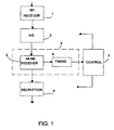
- the receiving end of a mobile station arranged to operate in a GSM network is illustrated in figure 1 for the parts that are related to the present invention.
- the RF signal received by the mobile station is supplied to the RF receiver 1 and a low frequency signal is forwarded from there to the A/D converter 2.
- the signal samples, such as the TDMA bursts are forwarded to the detection and demodulation unit 3. From this unit the signal is forwarded to the decryption unit 4.
- control unit 7 With help of the control unit 7, the operation of the mobile station is controlled and monitored.
- the detection and demodulation unit 3 comprises a receiving unit 5 and a timing unit 6.
- the receiving unit 5 is preferably implemented as an optimized receiver construction and it is in this embodiment a Maximum Likelihood Sequence Estimator MLSE. Function of the MLSE receiver 5 is to estimate the radio communication channel with help of those signal structures that are included in the transmitted signal for facilitating the estimation.
- a correction signal is determined from the received signal, said correction signal indicating the starting point of the page and being forwarded to the control unit 7 to be processed further. With help of this output signal of the timing unit 6, that is, the correction signal, the timing of the clock system included in the correction unit 7 can be checked and, if necessary, corrected.
- the received signal includes, in addition to the original signal, also the same kind of signal copies as the original but received at different times than the original one. Additionally, the stage of the received signal can vary occasionally. For this reason the channel estimation is required for correcting the errors of the signal caused by the radio channel. For this purpose, structures are added to the signal for facilitating the estimation.
- a predefined bit pattern is added to a predefined point of the page in the radio signal. The receiver finds this bit pattern and makes the channel estimation based on that. This principle is used in the MLSE receiver 5.
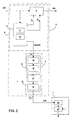
- the detection and demodulation unit 3 is illustrated as a block diagram in figure 2.
- the MLSE receiver 5 comprises a correlator 8 and an equalizer 9.
- the impulse response of the transmission channel is calculated in a certain time slot of the received signal, like the TDMA burst.
- This time slot is a part of the received signal, said time slot comprising data bits and a known bit pattern related to the synchronizing.
- Calculation of the impulse response of the channel is based on the correlation between the known bit pattern saved to the correlator 8 and the corresponding bit pattern expressed in the received time slot. So, the known bit pattern is saved to the memory unit 10 of the correlator 8, from where it is retrieved to the processing unit 11 of the correlator when counting the correlation.
- the processing unit comprises e.g. a microprocessor or a corresponding data processing and calculating means.
- the input signal of the correlator 8 is a complex signal a(t) that consists of I and Q signals (the GSM mobile communication system/GMSK modulation).
- the impulse responses are calculated for both I and Q signals.
- the calculated impulse responses are the estimates of the channel conditions during the respective time slot of the received signal.
- the input signal a(t) is subject to the following calculations that are performed in the processing unit 11 of the correlator for receiving the desired output signal maxpos for the timing unit 6.
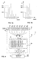
- a group of impulse response tabs is calculated in the processing unit 11, but usually all these are not fed to the equalizer 9. So, the calculated impulse response tabs are subject to selection and the tabs that give the best channel impulse response are selected. The selection is implemented in the processing unit 11 so that among all calculated impulse response tabs those are selected that include the most of energy. Further, it must be noticed that the selected tabs always form a group, that is, the correlator 11 can't select one tab here and one tab there. In this respect reference is made to figures 3a and 3b.
- Figure 3a shows how the magnitudes of nine impulse response tabs have been calculated and figure 3b shows the group of five tabs selected among those.
- the I D and Q D outputs of the correlator 8 are combined into the equalizer 9.
- the received signal a(t) is also fed to the equalizer 9.
- the purpose of the equalizer 9 is to equalize the received signal a(t) with help of the estimated channel impulse response.
- the technique in itself is widely known. It employs a matched filter and a modified Viterbi algorithm for signal processing.
- the estimated impulse response tabs are fed to the matched filter and processed.
- the output of the equalizer 9 gives an equalized signal b(t) for the decryption unit 4 (compare figure 1).
- the position signal maxpos calculated in the correlator 8 expresses the position of the maximum energy (that is, the position of the impulse response, the energy content of which is the biggest) in the received TDMA (like GSM) burst. For one received burst one position signal is received.
- the position signal maxpos is fed to the timing unit 6.
- This timing unit 6 comprises two filter units 14, 15 that are series connected with each other.
- the position signal output of the correlator 8 is connected to the input 12 of the first filter unit.
- the output 13 of the timing unit 6, which is also the output of the second filter unit, is further connected to the control unit 7.
- the first filter unit 14 comprises a first filter 16 and a separator 18 following this. By the separator 18, only desired output signals of the first filter 16 are allowed to pass to the second filter unit 15.
- the second filter unit 15 comprises a second filter 17 and a scaler 19.
- the output signal corr of the timing unit 6 is set to the suitable scaling window for the purpose of compensating the timing errors.
- the first filter 16 comprises an n state floating register 20 (figure 4), that is preferably a fifo-register (that is, a floating register where one signal sample comes in whereby another goes out).
- the position signal maxpos received from the correlator 8 is fed to the first filter 16, that is, in this case to the input 12 of the fifo register 20.
- the maxpos value of the position signal expresses the position of the maximum energy of the impulse response, and it can be calculated in connection with the calculation of the impulse response in the correlator 8, as described above.
- the calculated position signals maxpos are fed one after another to the fifo register 20 of the first filter 16, and after input of each signal the sum of the signal samples in the register 20 is calculated by the summer 21, after which the received sum "sum” is further fed to the decision unit 22, where the sum is compared with the decision parameters, and the intermediate output signal is given, based on the comparison, further to the separator 18.
- the sum "sum” of the position signals present in the register 20 at a certain moment is compared in the decision unit 22 with the decision parameters.
- the information of the nominal stage of the position signal is required. It can be in principle any signal value, so let it be nom, which is an integral number.
- the first decision parameter is formed from the sum of the nominal values of the position signals.
- the other decision parameters a n , b n are integral numbers that are suitably selected depending on the application.
- the fifo register 20 consists of eight memory elements 201, 20 2 , ..., 20 8 (Pos1, Pos2, Pos3, ..., Pos8) where eight successive position signals are saved into.
- the values of the other decision parameters a n , b n are 11, 7, 3 and the corresponding values of the intermediate signals ot: -3, -2, -1, 0, 1, 2, 3. From the decision table 22a of the decision unit 22 can be derived the intermediate signal ot, the value of which is one of said integral numbers: -3, -2, -1, 0, 1, 2, 3.
- the decision unit 22 comprises in addition to the decision table 22a also the summer 22b.
- the cumulative intermediate signal op represents the output signal of the decision unit 22.
- the cumulative intermediate signal op can be used as output signal of the first filter unit 14, but in most cases it is preferable to smoothen the output signal by feeding it first to the separator 18.
- the correction signal corr is received every other time, when the maxpos signal is entered.
- the correction of the timing is attenuated and smoothened so that it does not happen too fast and suddenly with respect of the units following it, especially those of the control unit 7 and the MLSE receiver 5.
- the second filter unit 15 includes an m state floating register 23.
- This floating register is preferably a fifo-register and its structure corresponds to the fifo register 20 of the first filter.
- the output signal op; D of the first filter unit 14 is fed into the input of the register 23.
- the successive op; D values of the output signals are saved to the memory elements 23 1 , 23 2 , 23 3 , ...23 m (Pos1, Pos2, Pos3, ..., Posm) of the floating register 23.
- the content of the register 23 is averaged, that is, the mean value is calculated from the op; D values of the included output signals of the first filter unit: the sum of the signals sum1 is calculated with the summer 24 and the result is divided by the number m of the elements 23 1 , 23 2 , 23 3 , ...23 m of the register 24 in the averaging unit 25.
- the signal ave 1 is the output signal of the second filter unit 15.
- a scaler 19 to the second filter unit 15, where the intermediate signal ave 1 of the second filter unit is fed to. So it is just the output signal corr of the scaler 19 that forms the output signal of the second filter unit 15 and at the same time the output signal of the timing unit 6, that is the timing correction signal. In this way the timing error correction is made more slowly in order to prevent the system from falling into an unstable state.
- the correction signal corr is received from the timing unit 6 every other time, when the position signal maxpos is entered and the range of this correction signal corr is limited to the half of the range of the intermediate signal ave 1.
- the output signal of the timing unit 6, that is, the correction signal corr is fed into the control unit 7 of the mobile station.
- the correction signal corr includes in principal information, whether the timing is OK, and if not, how big the error is and in which direction.
- the fast normal clock of the sleep clock system can be replaced between two pages by the sleep clock and the right timing of the mobile station is still maintained. It must be noticed, that the sleep clock can operate also at another time than between two pages (e.g. when the mobile station is used for communication).
- the correction signal corr of the timing unit 6 is processed in the control unit e.g. in the following way.
- the control unit 7 comprises a derivation unit 26 (figure 2), where the correction signal corr is fed to.
- the correction signal corr is derived, whereby it is possible to find out, when the timing of the clock system must be changed and to which direction.
- the output signal of the deriving unit 26, in turn, is fed to the clock unit like e.g. sleep clock system 27 in order to correct the timing so that the starting point of the page is synchronized with the clock signal.
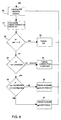
- the internal timing of the mobile station is corrected in the embodiment described above in the following way (compare flow diagram of figure 6).
- the position signal maxpos values are calculated in the correlator 8, as described above (phase 30). In the embodiment described above, these are integral numbers the range of which depends on the width of the correlating window of the correlator 8.
- the position signal maxpos values can range e.g. between -4, -3, ..., 3, 4 or 0, 1, 2, 3, 4. From these position signal values the correction signal corr is calculated in the timing unit 6 (phase 31).
- the correction signal calculated from the position signals maxpos with help of the timing unit 6 is corr ⁇ 0. This is noticed at the testing phase of the correction signal (phase 32).
- the correction signal corr of the timing unit 6 indicates that the frequency of the mobile station clock has changed and the timing of the clock system must be corrected.
- the output signal corr received from the timing unit 6 is one indicator relating to the timing error correction in the control unit 17; additionally, also other information relating to the timing error correction can be used for controlling and synchronizing the timing.
Landscapes
- Engineering & Computer Science (AREA)
- Computer Networks & Wireless Communication (AREA)
- Signal Processing (AREA)
- Synchronisation In Digital Transmission Systems (AREA)
- Mobile Radio Communication Systems (AREA)
Description
- The present invention concerns a method in accordance with the preamble of
claim 1 for compensating timing errors of a mobile station, particularly those of a digital mobile station. - The invention also concerns a circuitry in accordance with the preamble of
claim 7 for compensating timing errors of a mobile station, particularly those of a digital mobile station. - Adapted to a mobile station, there is known in the art a clock system that operates the whole time with high frequency. One drawback of this system is that the clock system wears a considerable amount of energy, whereby it is not suitable especially for small and lightweight mobile stations like mobile phones. In order to save the battery of the mobile station, a new clock system, a so called sleep clock system has been developed.
- One sleep clock system known in the art is disclosed in EP-0586256 A. The sleep clock system comprises two clock devices, the first of which is arranged to act with high frequency and the second with low frequency. The first clock device, the normal clock, operates on the megahertz band and the second clock device, the sleep clock, on the kilohertz band. The first clock device is switched off and the second clock device with lower accuracy is employed instead, when the mobile station is in a rest condition. By this arrangement the power consumption can be significantly decreased.
- The sleep clock system described above is used e.g. in mobile stations of the GSM (Global System for Mobile Communications) system based on time division multiple access (TDMA). When the normal clock device of the mobile station's sleep clock system is switched off, the receiver of the mobile station is arranged to receive radio signals from the base station only in certain predefined time stamps. The sleep time of the mobile station between two pages, said page being the time it is prepared to recognize an eventual incoming call, is relatively long, in the range of 1 to 2 seconds. This time slot must be accurately measurable.
- One problem of the present mobile stations, in which the sleep clock arrangement is used, is that there is generally used a crystal as a heart of the second clock device for synchronizing it. The crystal is always involved with frequency jitter that is in this application typically in the range of 0,5 µs. In a GSM mobile station this corresponds to about 1/8 of a bit period.
- In addition, one problem is that the frequency of the crystal changes according to the temperature changes. The nominal frequency is in general achieved at a temperature of 25°C. It can be stated that the bigger the temperature difference compared e.g. with the nominal temperature of 25°C is, the bigger is the frequency shift. A mobile station must operate reliably in a temperature range from -10°C up to +55°C. Based on the maximum change speed of the frequency, and taking into account that the sleep time between two pages in the GSM system is max. 2.12 s, it can be estimated that a timing error between starts of two pages is in the worst case about 6.2 µs/C. Further, if we estimate that the present lightweight mobile stations can warm/cool e.g. 1°C/min, the resulting timing error for a period of one minute is about 6.2 µs. When that is divided by the paging frequency, the resulting time error in the worst case between to pages is 0.2 µs. Even though the time error between two pages is not big, it is cumulative. In case the frequency shift, that is, the cumulative timing error is not compensated by some means, it will soon make the communication system between the mobile station and the base station to fail.
- In addition to the above mentioned crystal, another problem is involved with the sleep clock arrangement. A timing error of the same kind as the frequency jitter is generated when the clock frequency of the sleep clock system is changed. The second clock of the sleep clock system, in other words, the sleep clock, operates in the kilohertz band, whereas the normal clock operates in the megahertz band. The first clock operating with higher frequency must be on before the clock frequency can be changed from the second clock to the first one. The change of the clock frequency is an asynchronous process. In connection with each change, the stabilization of the normal clock takes some time. The timing error related to the change is in that case half of a clock cycle of the normal clock, that is, about 0.5 µs. The start of a paging function is also an asynchronous process. The signal receiver of the mobile station cannot be sure that the received paging signal really starts at the edge of the signal of its normal clock. Accordingly, this also involves a timing error that is a half of a clock cycle of a normal clock, that is about 0.5 µs.
- Based on what has been stated above, it can be estimated that in the worst case the total timing error between two pages will be formed as follows:
Frequency jitter of the crystal 0.5 µs Temperature roaming of the crystal 0.2 µs Change of clock frequency 0.5 µs Starting point of page 0.5 µs 1.7 µs/page - So, the total timing error between two pages is 1.7 µs, that is about a half of a bit period of the GSM network.
- The channel conditions have a significant influence on how well the radio frequency (RF) receiver can receive an RF signal transmitted from the base station. When the mobile station operates during the page with the normal clock frequency, the variations and changes of the channel conditions can be fairly good estimated and so the RF signal transmitted by the base station can be received by the receiver of the mobile station. When the timing error of the own internal clock system of the mobile station must also be estimated in the mobile station, the situation will be changed. The RF signal receiver of the mobile station can't be sure that the page transmitted by the base station starts at the very moment that is indicated by its own timing device. The eventual frequency error of the sleep clock system can also look like an error caused by bad channel conditions.
- When the channel conditions are bad, in other words, when there are deep fades and a lot of reflections (caused e.g. by a hilly landscape and a Doppler effect) in the received RF signal, the clock system of the mobile station easily fails in synchronizing. The elements of the mobile station can't judge, if the timing error is caused by bad channel conditions or by the clock system. The elements of the mobile station aim at keeping up the timing signal of the mobile station and its synchronizing in respect to the base station clock. Based on this, a correction signal is tried to be estimated in order to correct the long term timing error, in other words, the frequency error. Bad channel conditions can be expressed as a frequency error of the internal timing of the mobile station. This very soon makes the mobile station to loose the synchronizing to the signal frame structure with respect to the base station. It must be noticed that the sleep clock system is not stable in bad channel conditions, even if an optimized receiver construction like the Maximum Likelihood Sequence Estimator (MLSE) were used.
- US-5428820 describes a sleep clock system where firstly a timing error of the radio telephone is compensated by turning on its radio receiver in advance before receiving a timing signal from the remote transceiver. Secondly the sleep time of the radio telephone is checked and amended when a valid timing signal is received. The new sleep time is obtained by utilising the amount of time elapsed between the previous start signal generated by the sleep clock system of the telephone at the time, when the valid timing signal was received and adjust the sleep time accordingly.
- EP 0551803 A1 describes a method of synchronizing and channel estimation in a TDMA radio communication system. In this method a training sequence is locally generated and a channel estimate based on the comparison of the received signal frame and the locally generated training sequence is determined. In a first vector, which comprises M correlation values, is calculated and the position of the centre of energy is determined. The second vector comprising N consecutive correction values distributed around the centre of energy is chosen to form the channel estimate. The centre of energy in the second vector is chosen as synchronizing position. It is not mentioned that said vectors can be utilized for compensating internal timing errors of a mobile station.
- An object of the present invention is to provide a new method and a circuitry for compensating the timing errors of a mobile station, particularly those of a digital mobile station. An object of the present invention is particularly to provide a new method and circuitry for specifying, based on the RF signal received by the mobile station, a correction signal, by means of which the eventual timing errors of the clock system can be compensated.
- The method in accordance with the present invention is characterized in what has been stated in
claim 1. According to the invention, the method for compensating the internal timing errors of a digital mobile station has the following steps: - a) estimating a channel impulse response,
- b) determining from the channel impulse response signal samples that include a maximum amount of energy and the position signals (maxpos) of these maximum signal samples;
- c) determining by means of successive position signals (maxpos) a correction signal that indicates the magnitude and direction of the timing error of the mobile station, and
- d) checking by means of the correction signal the timing of the mobile station and, if necessary, synchronizing.
-
- The circuitry in accordance with the present invention is characterized in what has been stated in
claim 7. According to the invention, the circuitry for compensating the internal timing errors of a digital mobile station, comprises: - a correlator having a processing unit for determining from a channel impulse response estimated in a way known in the art the signal samples that include a maximum amount of energy and the position signals of these maximum signal samples; and
- a timing unit, adapted do determine with help of the successive position signals, a correction signal is determined, that indicates the magnitude and direction of the timing error of the mobile station and;
- a control unit (7) adapted to check and, if necessary, synchronise the timing of the mobile station and in particular that of its clock system.
- An advantage of the invention is the simple and efficient way of detecting and compensating internal timing errors (or errors interpreted as those) in a digital mobile station. Internal timing errors are due to the structure and operation of the mobile station, such as the internal clock crystal and/or connection of the clock system and the frequency changes related thereto.
- A further advantage of the present invention is that it can be integrated as a substantial part to the mobile station, irrespective of the clock system that is used in it. By means of the method and circuitry in accordance with the invention, a correction signal is produced, by means of which the timing errors of the mobile station and in particular those of its clock system can be detected and corrected.
- A particular advantage of the invention is that it facilitates the implementation of a reliable sleep clock system.
- In the following, the present invention and its further advantages are described with reference to the enclosed drawings, wherein
- Figure 1 illustrates as a block diagram a part of the receiving end of the mobile station with a circuitry according to the invention adapted thereto;
- Figure 2 illustrates as a block diagram a detection-demodulating unit of a mobile station;
- Figures 3a and 3b illustrate impulse response tabs and respectively a selected subgroup thereof;
- Figure 4 illustrates a first filter unit of the timing unit as a block diagram;
- Figure 5 illustrates a second filter unit of the timing unit as a block diagram; and
- Figure 6 illustrates as a flow diagram one method according to the invention for checking and correcting the timing of the mobile station.
-
- The receiving end of a mobile station arranged to operate in a GSM network is illustrated in figure 1 for the parts that are related to the present invention. The RF signal received by the mobile station is supplied to the
RF receiver 1 and a low frequency signal is forwarded from there to the A/D converter 2. The signal samples, such as the TDMA bursts are forwarded to the detection anddemodulation unit 3. From this unit the signal is forwarded to thedecryption unit 4. - With help of the
control unit 7, the operation of the mobile station is controlled and monitored. - The detection and
demodulation unit 3 comprises a receivingunit 5 and atiming unit 6. By means of the receivingunit 5 the signal is detected and demodulated. The receivingunit 5 is preferably implemented as an optimized receiver construction and it is in this embodiment a Maximum Likelihood Sequence Estimator MLSE. Function of theMLSE receiver 5 is to estimate the radio communication channel with help of those signal structures that are included in the transmitted signal for facilitating the estimation. By means of thetiming unit 6, a correction signal is determined from the received signal, said correction signal indicating the starting point of the page and being forwarded to thecontrol unit 7 to be processed further. With help of this output signal of thetiming unit 6, that is, the correction signal, the timing of the clock system included in thecorrection unit 7 can be checked and, if necessary, corrected. - As it is well known, there are changes occurring continuously in the transmission channel, which changes influence the radio signal by causing multipath fading and Doppler dispersion. Thus, the received signal includes, in addition to the original signal, also the same kind of signal copies as the original but received at different times than the original one. Additionally, the stage of the received signal can vary occasionally. For this reason the channel estimation is required for correcting the errors of the signal caused by the radio channel. For this purpose, structures are added to the signal for facilitating the estimation. One possibility is that a predefined bit pattern is added to a predefined point of the page in the radio signal. The receiver finds this bit pattern and makes the channel estimation based on that. This principle is used in the
MLSE receiver 5. - The detection and
demodulation unit 3 is illustrated as a block diagram in figure 2. TheMLSE receiver 5 comprises acorrelator 8 and anequalizer 9. With help of thecorrelator 8, the impulse response of the transmission channel is calculated in a certain time slot of the received signal, like the TDMA burst. This time slot is a part of the received signal, said time slot comprising data bits and a known bit pattern related to the synchronizing. Calculation of the impulse response of the channel is based on the correlation between the known bit pattern saved to thecorrelator 8 and the corresponding bit pattern expressed in the received time slot. So, the known bit pattern is saved to thememory unit 10 of thecorrelator 8, from where it is retrieved to theprocessing unit 11 of the correlator when counting the correlation. The processing unit comprises e.g. a microprocessor or a corresponding data processing and calculating means. - The input signal of the
correlator 8 is a complex signal a(t) that consists of I and Q signals (the GSM mobile communication system/GMSK modulation). In thecorrelator 8, the impulse responses are calculated for both I and Q signals. The calculated impulse responses are the estimates of the channel conditions during the respective time slot of the received signal. - The input signal a(t) is subject to the following calculations that are performed in the
processing unit 11 of the correlator for receiving the desired output signal maxpos for thetiming unit 6. The magnitude of the estimated impulse response can be calculated by the following formula:Q - A group of impulse response tabs is calculated in the
processing unit 11, but usually all these are not fed to theequalizer 9. So, the calculated impulse response tabs are subject to selection and the tabs that give the best channel impulse response are selected. The selection is implemented in theprocessing unit 11 so that among all calculated impulse response tabs those are selected that include the most of energy. Further, it must be noticed that the selected tabs always form a group, that is, thecorrelator 11 can't select one tab here and one tab there. In this respect reference is made to figures 3a and 3b. Figure 3a shows how the magnitudes of nine impulse response tabs have been calculated and figure 3b shows the group of five tabs selected among those. The selection algorithm for five impulse response tabs is so that the magnitudes m(i) of the impulse tabs of this group are calculated by formula 2:i = 4-s, 3-s, 2-s, ..., 4+s, whereby s = the window width of the impulse response.
- From the group m(i) of the calculated impulse response tabs the subgroup of those tabs is looked for that includes the maximum quantity of energy (figure 3b). From this subgroup the impulse response tab is selected that includes the maximum quantity of energy compared with the other tabs of the subgroup, and the location of this is expressed as a position signal maxpos according to formula 3:
- The final impulse response will be calculated by formula 4:
- The ID and QD outputs of the
correlator 8 are combined into theequalizer 9. The received signal a(t) is also fed to theequalizer 9. The purpose of theequalizer 9 is to equalize the received signal a(t) with help of the estimated channel impulse response. The technique in itself is widely known. It employs a matched filter and a modified Viterbi algorithm for signal processing. The estimated impulse response tabs are fed to the matched filter and processed. The output of theequalizer 9 gives an equalized signal b(t) for the decryption unit 4 (compare figure 1). - The position signal maxpos calculated in the
correlator 8 expresses the position of the maximum energy (that is, the position of the impulse response, the energy content of which is the biggest) in the received TDMA (like GSM) burst. For one received burst one position signal is received. - The position signal maxpos is fed to the
timing unit 6. Thistiming unit 6 comprises twofilter units correlator 8 is connected to theinput 12 of the first filter unit. Theoutput 13 of thetiming unit 6, which is also the output of the second filter unit, is further connected to thecontrol unit 7. - The
first filter unit 14 comprises afirst filter 16 and aseparator 18 following this. By theseparator 18, only desired output signals of thefirst filter 16 are allowed to pass to thesecond filter unit 15. - The
second filter unit 15 comprises asecond filter 17 and ascaler 19. By thescaler 19 the output signal corr of thetiming unit 6 is set to the suitable scaling window for the purpose of compensating the timing errors. - The
first filter 16 comprises an n state floating register 20 (figure 4), that is preferably a fifo-register (that is, a floating register where one signal sample comes in whereby another goes out). The position signal maxpos received from thecorrelator 8 is fed to thefirst filter 16, that is, in this case to theinput 12 of thefifo register 20. The maxpos value of the position signal expresses the position of the maximum energy of the impulse response, and it can be calculated in connection with the calculation of the impulse response in thecorrelator 8, as described above. - The calculated position signals maxpos are fed one after another to the
fifo register 20 of thefirst filter 16, and after input of each signal the sum of the signal samples in theregister 20 is calculated by thesummer 21, after which the received sum "sum" is further fed to thedecision unit 22, where the sum is compared with the decision parameters, and the intermediate output signal is given, based on the comparison, further to theseparator 18. The output of theseparator 18 and, simultaneously, the output of thefirst filter 14, gives the output signal of the first filter unit to be fed to thesecond filter unit 15. - In the following we deal in detail with the procedures that are implemented in connection with the
first filter unit 14. The sum "sum" of the position signals in thefifo register 20 is calculated with thesummer 21 according to formula 5:wherein
d(i) is the content of thememory element - The sum "sum" of the position signals present in the
register 20 at a certain moment is compared in thedecision unit 22 with the decision parameters. For determination of the decision parameters, the information of the nominal stage of the position signal is required. It can be in principle any signal value, so let it be nom, which is an integral number. The sum of the n position signals with nominal value is ave = n * nom. This value ave is compared with the real sum "sum" of the position signals received from thesummer 21. If the sum "sum" of the real position signals is bigger than the sum ave, it means that the position signals differ a lot from the estimated nominal stage and, accordingly, that the value of the timing correction to be performed, that is, the value of the correction signal, must be big. By using if-so statements the values of the intermediate signals ot to be selected, Nn, Nn-1, ..., N2, N1, NP, P1, P2, ..., Pn-1, Pn, can be expressed in the form of table 6:IF sum < ave - an SO ot = Nn IF sum < ave - an-1 SO ot = Nn-1 . . IF sum < ave - a2 SO ot = N2 IF sum < ave - a1 SO ot = N1 IF ave - a1 < sum < ave + b1 SO ot = NP IF sum > ave + b1 SO ot = P1 IF sum > ave + b2 SO ot = P2 . . IF sum > ave + bn-1 SO ot = Pn-1 IF sum > ave + bn SO ot = Pn - The decision parameters are ave-an, ave-bn, wherein n = 1, 2, 3, ... (integral number). The first decision parameter is formed from the sum of the nominal values of the position signals. The other decision parameters an, bn are integral numbers that are suitably selected depending on the application. This is illustrated in figure 4 by the decision table 22a included in the
decision unit 22, in accordance with the following table 7:IF sum < ave -11 SO ot = -3 IF sum < ave -7 SO ot = -2 IF sum < ave -3 SO ot = -1 IF ave -3 < sum < ave +3 SO ot = 0 IF sum > ave +3 SO ot = 1 IF sum > ave +7 SO ot = 2 IF sum > ave +11 SO ot = 3 - In the example of figure 4, the
fifo register 20 consists of eightmemory elements decision unit 22 can be derived the intermediate signal ot, the value of which is one of said integral numbers: -3, -2, -1, 0, 1, 2, 3. - In this embodiment the
decision unit 22 comprises in addition to the decision table 22a also thesummer 22b. The first intermediate signal received from the decision table 22a of the decision unit is summed in thesummer 22b with the corresponding intermediate signal calculated earlier in the previous phase, whereby the cumulative intermediate signal is received according to formula 8: - The cumulative intermediate signal op represents the output signal of the
decision unit 22. - The cumulative intermediate signal op can be used as output signal of the
first filter unit 14, but in most cases it is preferable to smoothen the output signal by feeding it first to theseparator 18. Theseparator 18 passes through every Dth signal, whereby D is an integral number fromgroup separator 18, and D = 2, so the output signal of theseparator 18, that is, the series of the op;D (D = 2) of the output signals of the first filter unit is op0, op2, op4, op6, ... (compare figure 4). Thus, in this embodiment the correction signal corr is received every other time, when the maxpos signal is entered. With help of theseparator 18, the correction of the timing is attenuated and smoothened so that it does not happen too fast and suddenly with respect of the units following it, especially those of thecontrol unit 7 and theMLSE receiver 5. - Referring now to figure 5, the
second filter unit 15 includes an mstate floating register 23. This floating register is preferably a fifo-register and its structure corresponds to thefifo register 20 of the first filter. The output signal op; D of thefirst filter unit 14 is fed into the input of theregister 23. The successive op; D values of the output signals are saved to thememory elements register 23. The content of theregister 23 is averaged, that is, the mean value is calculated from the op; D values of the included output signals of the first filter unit: the sum of the signals sum1 is calculated with thesummer 24 and the result is divided by the number m of theelements register 24 in the averagingunit 25. The mean value of the signals included in all elements of theregister 23 is ave1 = suml/m. Thesignal ave 1 is the output signal of thesecond filter unit 15. - It is, however, preferable to arrange additionally a
scaler 19 to thesecond filter unit 15, where theintermediate signal ave 1 of the second filter unit is fed to. So it is just the output signal corr of thescaler 19 that forms the output signal of thesecond filter unit 15 and at the same time the output signal of thetiming unit 6, that is the timing correction signal. In this way the timing error correction is made more slowly in order to prevent the system from falling into an unstable state. - The function of the
scaler 19 of thesecond filter unit 15 is to adapt the output signal of the second filter to those correction limits, in other words, variation limits, within which the MLSE receiver can process the output signal. If the timing error correction is too fast, the whole receiver falls into an unstable state and starts to oscillate. If the timing error correction is too slow, the MLSE receiver is not fast enough to perform the correction, that is received from the clock system of the mobile station through thecontrol unit 7. Accordingly, the following procedure is implemented by thescaler 19 to theintermediate signal ave 1 fed into it:ave 1/sca, - In the second filter unit illustrated by figure 5, the number of the op; D values of the output signals of the first filter unit which values can be collected to register 23 is m = 8 and the parameter of the
scaler 19 is sca = 2. Thus, in this embodiment the correction signal corr is received from thetiming unit 6 every other time, when the position signal maxpos is entered and the range of this correction signal corr is limited to the half of the range of theintermediate signal ave 1. - The output signal of the
timing unit 6, that is, the correction signal corr is fed into thecontrol unit 7 of the mobile station. The correction signal corr includes in principal information, whether the timing is OK, and if not, how big the error is and in which direction. By means of this arrangement, for example, the fast normal clock of the sleep clock system can be replaced between two pages by the sleep clock and the right timing of the mobile station is still maintained. It must be noticed, that the sleep clock can operate also at another time than between two pages (e.g. when the mobile station is used for communication). - The correction signal corr of the
timing unit 6 is processed in the control unit e.g. in the following way. Thecontrol unit 7 comprises a derivation unit 26 (figure 2), where the correction signal corr is fed to. Here the correction signal corr is derived, whereby it is possible to find out, when the timing of the clock system must be changed and to which direction. The output signal of the derivingunit 26, in turn, is fed to the clock unit like e.g.sleep clock system 27 in order to correct the timing so that the starting point of the page is synchronized with the clock signal. - The internal timing of the mobile station is corrected in the embodiment described above in the following way (compare flow diagram of figure 6). The position signal maxpos values are calculated in the
correlator 8, as described above (phase 30). In the embodiment described above, these are integral numbers the range of which depends on the width of the correlating window of thecorrelator 8. The position signal maxpos values can range e.g. between -4, -3, ..., 3, 4 or 0, 1, 2, 3, 4. From these position signal values the correction signal corr is calculated in the timing unit 6 (phase 31). The value of the correction signal corr is in general an integral number that indicates how big the timing error of the mobile station clock is. In this embodiment of the GSM network the timing error is given with an accuracy of 1/4 bit period (= 923 ns). - At the beginning the correction signal of the
timing unit 6 is corr = 0. This is tested (phase 32) in thecontrol unit 7 and it is noticed that the timing is OK (phase 33), in other words, no error is found in it and there is no need to correct the timing. When paging is started with the mobile station and time passes, it happens at some point that the correction signal calculated from the position signals maxpos with help of thetiming unit 6 is corr ≠ 0. This is noticed at the testing phase of the correction signal (phase 32). Thus, the correction signal corr of thetiming unit 6 indicates that the frequency of the mobile station clock has changed and the timing of the clock system must be corrected. - Let us assume that the following correction signal received from the
timing unit 6 is corr = 1. This change of the correction signal is noticed at the testing phases, where it is first noticed that corr ≠ 0 (phase 32) and that the value of the correction signal corr has changed (phase 34) and, in particular, that it has increased (phase 35) by the value Δ= +1. The timing will be changed according to the change Δ of the correction signal corr (phase 36). With help of thecontrol unit 7, the other parts of the mobile station are informed that due to the frequency change of the clock system like a clock crystal, the normal clock included in thesleep clock system 27 of the mobile station must be activated next time by Δx1/4 bit period (= Δ x 923 ns), wherein Δ = +1, earlier than at this observation time. In this way the timing error caused by the frequency change of the clock system will be corrected. - Let us further assume that the correction signal of the
timing unit 6 is corr = 1. Next time the correction signal corr gets the value corr = 2. This information is given by thetiming unit 6 to thecontrol unit 7, by which the positive change of the correction signal corr, that is, addition Δ = +1 is detected (phases 32, 34, 35) and the timing will be changed again with help of thecontrol unit 7, as described above. Let us further assume that the correction signal corr next time changes to value corr = 1, whereby thecontrol unit 7 again reacts to the change, and the value of the correction signal corr this time decreases. The change Δ= -1 of the correction signal corr is detected at the testing phases, whereby the first observation is that corr ≠ 0 (phase 32) and that the value of the correction signal corr has changed (phase 34) and, in particular, decreased (phase 35). The timing will be changed according to the negative change of the correction signal corr, in other words, according to the Δ = -1 (phase 37). With help of thecontrol unit 7, the mobile station will be adjusted to be activated the next time by Δ x 1/4 bit period (= Δ x 923 ns), wherein Δ = -1, later than the previous time. - Let us further assume, that the correction signal of the
timing unit 6 is corr = 1. This value of the correction signal corr keeps constant for the next testing period. This is noticed in the control unit 7 (phases 32 and 34) and the timing correction is kept constant (phase 39), in other words, by the timing correction value determined earlier. - In connection with the
control unit 7 there is a sleep clock system with a certain constant time, that the normal fast clock is switched off and during which the sleep clock and its crystal is used. This constant time is shortened/lengthened for one step Δ = 1 (Δ x 1/4 bit period) respectively, when the output signal of thetiming unit 6 changes. It must be kept in mind, however, that preferably one unit change of the output signal makes only one unit change in the timing signal. - In the procedure described above (figure 6), the signal corr received by the
control unit 7 from thetiming unit 6 is derived and the timing of the sleep clock system is changed with help of the derivate of the corr signal. - It must be noticed that the output signal corr received from the
timing unit 6 is one indicator relating to the timing error correction in thecontrol unit 17; additionally, also other information relating to the timing error correction can be used for controlling and synchronizing the timing.
Claims (12)
- A method for compensating internal timing errors of a digital mobile station having the following steps:a) estimating a channel impulse response,b) determining from the channel impulse response signal samples that include a maximum amount of energy and the position signals (maxpos) of these maximum signal samples;c) determining by means of successive position signals (maxpos) a correction signal (corr) that indicates the magnitude and direction of the timing error of the mobile station, andd) checking by means of the correction signal the timing of the mobile station and, if necessary, synchronizing.
- A method in accordance with claim 1, wherein step c and d have the following bysteps:e) forming the sum (sum) of a group of successive position signals (maxpos);f) comparing the sum (sum) with suitable predetermined decision parameters (ave-11, ave-7,..., ave+7, ave+11);g) selecting an intermediate signal (ot, op) based on the comparison;h) calculating the mean value (ave1) of a certain group formed from the intermediate signals, andi) using the calculated mean value (ave1) to determine said correction signal (corr).
- A method in accordance with claim 2, wherein step f and g have the following bysteps:j) forming an if-so decision table (22a), wherein a first parameter (ave) is formed from a nominal value (nom) of the position signal group and second parameters (11, 7,..., -7, -11) are formed from suitably selected integral numbers, and from the differences of said first and second parameter said predetermined decision parameters are formed, andk) comparing the summed values (sum) of the position signal with said decision parameters, andl) selecting the value of the intermediate signal (ot) based on the comparison.
- A method in accordance with claim 2 or 3, wherein the method has the following bystep:m) forming the intermediate signal (op) cumulatively by summing the earlier calculated intermediate (ot) signal to it.
- A method in accordance with claim 2, 3 or 4, wherein the method has the following bystep:n) separating the Dth intermediate signal (D = 2, 3, 4, ...) from a successive group of the intermediate cumulated signals (op) to be processed when determining the correction signal.
- A method in accordance with any of the foregoing claims from 2 to 5,
wherein the method has the following bystep:o) scaling the mean value (ave1) by dividing it by a suitable number andp) using the resulted corrected mean value as said correction signal (corr) for compensating the timing errors. - A circuitry for compensating internal timing errors of a digital mobile station, wherein the circuitry comprises:a correlator (8) having a processing unit (11) for determining from a channel impulse response estimated in a way known in the art the signal samples that include a maximum amount of energy and the position signals (maxpos) of these maximum signal samples; anda timing unit (6), adapted to determine with help of the successive position signals (maxpos), a correction signal (corr), that indicates the magnitude and direction of the timing error of the mobile station; anda control unit (7) adapted to check and, if necessary, synchronize the timing of the mobile station and in particular that of its clock system.
- A circuitry in accordance with claim 7, wherein the timing unit (6) comprises two filter units (14, 15), said first filter unit (14) including an n state floating register (20), a summer (21) and a decision unit (22), and said second filter unit (15) including an m state floating register (23) and an averaging unit (24, 25).
- A circuitry in accordance with claim 8, wherein in the decision unit (22) an if-so table (22a) is formed containing predetermined decision parameters (ave-11, ave-7,..., ave+7, ave+11) obtained from differences of a first parameter (ave), formed from a nominal value (nom) of the position signals, and second parameters (11, 7,..., -7, -11) obtained from suitably selected integral numbers; and
wherein the decision unit (22) is adapted to select the value of an intermediate signal (ot) based on said comparison. - A circuitry in accordance with claim 9, wherein the decision unit (22) includes a summer (22b) for forming an intermediate signal (op) cumulatively by summing the earlier calculated intermediate (ot) signal to it.
- A circuitry in accordance with claim 10, wherein the first filter unit (14) includes a separator (18) for separating from a group of the successive correction values in succession the Dth (D = 2, 3, 4, ...) intermediate signal (op) to be processed in the second processing phase.
- A circuitry in accordance with any of the foregoing claims from 7 to 11, wherein the second filter unit (15) includes a scaler (26) adapted to scale the mean value (ave1) received from the averaging unit (24, 25) by dividing it by a suitable number, and to provide the received corrected mean value as said correction signal (corr) for compensating the timing errors.
Applications Claiming Priority (2)
| Application Number | Priority Date | Filing Date | Title |
|---|---|---|---|
| FI955045 | 1995-10-23 | ||
| FI955045A FI111582B (en) | 1995-10-23 | 1995-10-23 | A method and circuit arrangement for compensating for internal thought errors in a mobile station |
Publications (3)
| Publication Number | Publication Date |
|---|---|
| EP0771128A2 EP0771128A2 (en) | 1997-05-02 |
| EP0771128A3 EP0771128A3 (en) | 2003-07-09 |
| EP0771128B1 true EP0771128B1 (en) | 2005-08-03 |
Family
ID=8544244
Family Applications (1)
| Application Number | Title | Priority Date | Filing Date |
|---|---|---|---|
| EP96660064A Expired - Lifetime EP0771128B1 (en) | 1995-10-23 | 1996-10-01 | Method and circuitry for compensating internal timing errors of a mobile station |
Country Status (5)
| Country | Link |
|---|---|
| US (1) | US5917868A (en) |
| EP (1) | EP0771128B1 (en) |
| JP (1) | JP3923571B2 (en) |
| DE (1) | DE69635011T2 (en) |
| FI (1) | FI111582B (en) |
Families Citing this family (7)
| Publication number | Priority date | Publication date | Assignee | Title |
|---|---|---|---|---|
| WO1998018216A2 (en) * | 1996-10-24 | 1998-04-30 | Philips Electronics N.V. | A digital wireless communications system and a wireless radio station |
| ATE210348T1 (en) * | 1997-02-04 | 2001-12-15 | Nokia Networks Oy | COMPENSATION OF DOPPLER SHIFT IN A MOBILE COMMUNICATIONS SYSTEM |
| GB2323187B (en) * | 1997-03-14 | 2001-09-19 | Nokia Mobile Phones Ltd | Data processing circuit using both edges of a clock signal |
| US6370160B1 (en) * | 1998-12-29 | 2002-04-09 | Thomson Licensing S. A. | Base to handset epoch synchronization in multi-line wireless telephone |
| JP3689021B2 (en) * | 2001-05-25 | 2005-08-31 | 三菱電機株式会社 | Timing control apparatus and timing control method |
| US7653828B2 (en) * | 2004-05-28 | 2010-01-26 | Sap Ag | Timeout manager |
| EP2663128A4 (en) * | 2011-02-09 | 2015-07-01 | Panasonic Ip Man Co Ltd | Wireless device and wireless communication system |
Family Cites Families (6)
| Publication number | Priority date | Publication date | Assignee | Title |
|---|---|---|---|---|
| US5263026A (en) * | 1991-06-27 | 1993-11-16 | Hughes Aircraft Company | Maximum likelihood sequence estimation based equalization within a mobile digital cellular receiver |
| SE469678B (en) * | 1992-01-13 | 1993-08-16 | Ericsson Telefon Ab L M | SET FOR SYNCHRONIZATION AND CHANNEL TESTING IN TDMA RADIO SYSTEM |
| US5317595A (en) * | 1992-06-30 | 1994-05-31 | Nokia Mobile Phones Ltd. | Rapidly adaptable channel equalizer |
| US5428820A (en) * | 1993-10-01 | 1995-06-27 | Motorola | Adaptive radio receiver controller method and apparatus |
| FI96257C (en) * | 1994-04-13 | 1996-05-27 | Nokia Telecommunications Oy | A method for determining the phase error of a radio frequency signal, as well as a receiver |
| US5706314A (en) * | 1995-01-04 | 1998-01-06 | Hughes Electronics | Joint maximum likelihood channel and timing error estimation |
-
1995
- 1995-10-23 FI FI955045A patent/FI111582B/en not_active IP Right Cessation
-
1996
- 1996-09-23 US US08/717,570 patent/US5917868A/en not_active Expired - Lifetime
- 1996-10-01 DE DE69635011T patent/DE69635011T2/en not_active Expired - Lifetime
- 1996-10-01 EP EP96660064A patent/EP0771128B1/en not_active Expired - Lifetime
- 1996-10-17 JP JP27496296A patent/JP3923571B2/en not_active Expired - Fee Related
Also Published As
| Publication number | Publication date |
|---|---|
| FI955045A0 (en) | 1995-10-23 |
| US5917868A (en) | 1999-06-29 |
| JP3923571B2 (en) | 2007-06-06 |
| JPH09139710A (en) | 1997-05-27 |
| EP0771128A2 (en) | 1997-05-02 |
| FI955045A (en) | 1997-04-24 |
| DE69635011D1 (en) | 2005-09-08 |
| EP0771128A3 (en) | 2003-07-09 |
| DE69635011T2 (en) | 2006-02-09 |
| FI111582B (en) | 2003-08-15 |
Similar Documents
| Publication | Publication Date | Title |
|---|---|---|
| EP2436212B1 (en) | Movement sensor uses in communication systems | |
| US6961352B2 (en) | Method of synchronizing a radio terminal of a radio communication network and a corresponding radio terminal | |
| KR20120030342A (en) | System and method for operating a gps device in micro power mode | |
| AU748692B2 (en) | Reception synchronization circuit, receiver using the same, and digital communication system | |
| US7336751B2 (en) | Power control circuit and radio transmission apparatus | |
| EP0771128B1 (en) | Method and circuitry for compensating internal timing errors of a mobile station | |
| US6067295A (en) | Method and apparatus for reducing error in recovering information bits in a wireless system | |
| EP0959594A2 (en) | Weighted linear prediction, particularly for carrier recovery and channel estimation | |
| US7139333B2 (en) | Frequency error estimating receiver, and frequency error estimating method | |
| JP2007336152A (en) | Spread spectrum receiver and its method | |
| US20060146969A1 (en) | Joint synchronization and impairments estimation using known data patterns | |
| US6724837B1 (en) | Timing estimation for GSM bursts based on past history | |
| EP0894366B1 (en) | Adaptive compensation of doppler shift in a mobile communication system | |
| US6091786A (en) | Method and apparatus in a communication receiver for estimating symbol timing and carrier frequency | |
| US6614860B1 (en) | Compensation of doppler shift in a mobile communication system | |
| JP3980486B2 (en) | Frequency offset estimator | |
| US6553007B1 (en) | Compensation of doppler shift in a mobile communication system | |
| CN100372247C (en) | Downstream synchronization monitoring apparatus and method for mobile terminal and application thereof | |
| KR100817015B1 (en) | Method and apparatus for tracking clock frequency in mb-ofdm system | |
| SE504792C2 (en) | Frequency and time slot synchronization using adaptive filtering | |
| US20020057753A1 (en) | Method of correcting frequency error | |
| EP1261144A1 (en) | Method and system for optimising the length of a search window | |
| WO2002098009A1 (en) | Method and system for optimising the length of a search window | |
| JP4273880B2 (en) | Channel estimation apparatus and channel estimation method | |
| WO2004002092A1 (en) | Method for estimating noise auto-correlation |
Legal Events
| Date | Code | Title | Description |
|---|---|---|---|
| PUAI | Public reference made under article 153(3) epc to a published international application that has entered the european phase |
Free format text: ORIGINAL CODE: 0009012 |
|
| AK | Designated contracting states |
Kind code of ref document: A2 Designated state(s): DE FR GB SE |
|
| RAP1 | Party data changed (applicant data changed or rights of an application transferred) |
Owner name: NOKIA CORPORATION |
|
| PUAL | Search report despatched |
Free format text: ORIGINAL CODE: 0009013 |
|
| AK | Designated contracting states |
Designated state(s): DE FR GB SE |
|
| 17P | Request for examination filed |
Effective date: 20031125 |
|
| 17Q | First examination report despatched |
Effective date: 20040220 |
|
| GRAP | Despatch of communication of intention to grant a patent |
Free format text: ORIGINAL CODE: EPIDOSNIGR1 |
|
| GRAS | Grant fee paid |
Free format text: ORIGINAL CODE: EPIDOSNIGR3 |
|
| GRAA | (expected) grant |
Free format text: ORIGINAL CODE: 0009210 |
|
| AK | Designated contracting states |
Kind code of ref document: B1 Designated state(s): DE FR GB SE |
|
| REG | Reference to a national code |
Ref country code: GB Ref legal event code: FG4D |
|
| REF | Corresponds to: |
Ref document number: 69635011 Country of ref document: DE Date of ref document: 20050908 Kind code of ref document: P |
|
| REG | Reference to a national code |
Ref country code: SE Ref legal event code: TRGR |
|
| ET | Fr: translation filed | ||
| PLBE | No opposition filed within time limit |
Free format text: ORIGINAL CODE: 0009261 |
|
| STAA | Information on the status of an ep patent application or granted ep patent |
Free format text: STATUS: NO OPPOSITION FILED WITHIN TIME LIMIT |
|
| 26N | No opposition filed |
Effective date: 20060504 |
|
| REG | Reference to a national code |
Ref country code: FR Ref legal event code: TP |
|
| REG | Reference to a national code |
Ref country code: FR Ref legal event code: CD Owner name: 2011 INTELLECTUAL PROPERTY ASSET TRUST, US Effective date: 20111123 |
|
| REG | Reference to a national code |
Ref country code: DE Ref legal event code: R082 Ref document number: 69635011 Country of ref document: DE Representative=s name: COHAUSZ & FLORACK PATENT- UND RECHTSANWAELTE P, DE |
|
| REG | Reference to a national code |
Ref country code: DE Ref legal event code: R082 Ref document number: 69635011 Country of ref document: DE Representative=s name: TBK, DE Effective date: 20120215 Ref country code: DE Ref legal event code: R081 Ref document number: 69635011 Country of ref document: DE Owner name: CORE WIRELESS LICENSING S.A.R.L., LU Free format text: FORMER OWNER: NOKIA CORP., 02610 ESPOO, FI Effective date: 20120215 Ref country code: DE Ref legal event code: R081 Ref document number: 69635011 Country of ref document: DE Owner name: CORE WIRELESS LICENSING S.A.R.L., LU Free format text: FORMER OWNER: NOKIA CORP., ESPOO, FI Effective date: 20120215 |
|
| REG | Reference to a national code |
Ref country code: GB Ref legal event code: 732E Free format text: REGISTERED BETWEEN 20120322 AND 20120328 |
|
| REG | Reference to a national code |
Ref country code: FR Ref legal event code: TP Owner name: CORE WIRELESS LICENSING S.A.R.L., LU Effective date: 20120316 |
|
| REG | Reference to a national code |
Ref country code: DE Ref legal event code: R082 Ref document number: 69635011 Country of ref document: DE Representative=s name: TBK, DE |
|
| REG | Reference to a national code |
Ref country code: DE Ref legal event code: R082 Ref document number: 69635011 Country of ref document: DE Representative=s name: TBK, DE Effective date: 20120511 Ref country code: DE Ref legal event code: R081 Ref document number: 69635011 Country of ref document: DE Owner name: CORE WIRELESS LICENSING S.A.R.L., LU Free format text: FORMER OWNER: 2011 INTELLECTUAL PROPERTY ASSET TRUST, WILMINGTON, DEL., US Effective date: 20120511 |
|
| REG | Reference to a national code |
Ref country code: GB Ref legal event code: 732E Free format text: REGISTERED BETWEEN 20120614 AND 20120620 |
|
| PGFP | Annual fee paid to national office [announced via postgrant information from national office to epo] |
Ref country code: GB Payment date: 20141001 Year of fee payment: 19 Ref country code: DE Payment date: 20140923 Year of fee payment: 19 Ref country code: FR Payment date: 20141008 Year of fee payment: 19 Ref country code: SE Payment date: 20141013 Year of fee payment: 19 |
|
| REG | Reference to a national code |
Ref country code: DE Ref legal event code: R119 Ref document number: 69635011 Country of ref document: DE |
|
| REG | Reference to a national code |
Ref country code: SE Ref legal event code: EUG |
|
| GBPC | Gb: european patent ceased through non-payment of renewal fee |
Effective date: 20151001 |
|
| PG25 | Lapsed in a contracting state [announced via postgrant information from national office to epo] |
Ref country code: DE Free format text: LAPSE BECAUSE OF NON-PAYMENT OF DUE FEES Effective date: 20160503 Ref country code: GB Free format text: LAPSE BECAUSE OF NON-PAYMENT OF DUE FEES Effective date: 20151001 |
|
| REG | Reference to a national code |
Ref country code: FR Ref legal event code: ST Effective date: 20160630 |
|
| PG25 | Lapsed in a contracting state [announced via postgrant information from national office to epo] |
Ref country code: SE Free format text: LAPSE BECAUSE OF NON-PAYMENT OF DUE FEES Effective date: 20151002 Ref country code: FR Free format text: LAPSE BECAUSE OF NON-PAYMENT OF DUE FEES Effective date: 20151102 |