EP0770988B1 - Verfahren zur Sprachdekodierung und tragbares Endgerät - Google Patents
Verfahren zur Sprachdekodierung und tragbares Endgerät Download PDFInfo
- Publication number
- EP0770988B1 EP0770988B1 EP96307724A EP96307724A EP0770988B1 EP 0770988 B1 EP0770988 B1 EP 0770988B1 EP 96307724 A EP96307724 A EP 96307724A EP 96307724 A EP96307724 A EP 96307724A EP 0770988 B1 EP0770988 B1 EP 0770988B1
- Authority
- EP
- European Patent Office
- Prior art keywords
- speech
- gain
- filter
- noise
- period
- Prior art date
- Legal status (The legal status is an assumption and is not a legal conclusion. Google has not performed a legal analysis and makes no representation as to the accuracy of the status listed.)
- Expired - Lifetime
Links
- 238000000034 method Methods 0.000 title claims description 23
- 230000003595 spectral effect Effects 0.000 claims description 71
- 238000007493 shaping process Methods 0.000 claims description 40
- 238000001914 filtration Methods 0.000 claims description 20
- 230000005540 biological transmission Effects 0.000 claims description 6
- 230000015572 biosynthetic process Effects 0.000 description 70
- 238000003786 synthesis reaction Methods 0.000 description 70
- 239000013598 vector Substances 0.000 description 38
- 238000013139 quantization Methods 0.000 description 34
- 238000006243 chemical reaction Methods 0.000 description 23
- 238000001228 spectrum Methods 0.000 description 15
- 238000004364 calculation method Methods 0.000 description 10
- 230000006870 function Effects 0.000 description 9
- 230000005284 excitation Effects 0.000 description 8
- 238000010586 diagram Methods 0.000 description 7
- 238000011156 evaluation Methods 0.000 description 5
- 238000001308 synthesis method Methods 0.000 description 5
- 230000000694 effects Effects 0.000 description 4
- 238000012545 processing Methods 0.000 description 3
- 230000004044 response Effects 0.000 description 3
- 238000005070 sampling Methods 0.000 description 3
- 230000007704 transition Effects 0.000 description 3
- 230000008859 change Effects 0.000 description 2
- 238000001514 detection method Methods 0.000 description 2
- 239000011159 matrix material Substances 0.000 description 2
- 238000004904 shortening Methods 0.000 description 2
- 230000001052 transient effect Effects 0.000 description 2
- 238000004891 communication Methods 0.000 description 1
- 230000006835 compression Effects 0.000 description 1
- 238000007906 compression Methods 0.000 description 1
- 238000012937 correction Methods 0.000 description 1
- 230000003247 decreasing effect Effects 0.000 description 1
- 230000002542 deteriorative effect Effects 0.000 description 1
- 230000002708 enhancing effect Effects 0.000 description 1
- 230000001747 exhibiting effect Effects 0.000 description 1
- 238000009432 framing Methods 0.000 description 1
- 238000009499 grossing Methods 0.000 description 1
- 230000006872 improvement Effects 0.000 description 1
- 230000002035 prolonged effect Effects 0.000 description 1
- 230000002441 reversible effect Effects 0.000 description 1
- 230000005236 sound signal Effects 0.000 description 1
- 230000001629 suppression Effects 0.000 description 1
Images


Classifications
-
- G—PHYSICS
- G10—MUSICAL INSTRUMENTS; ACOUSTICS
- G10L—SPEECH ANALYSIS TECHNIQUES OR SPEECH SYNTHESIS; SPEECH RECOGNITION; SPEECH OR VOICE PROCESSING TECHNIQUES; SPEECH OR AUDIO CODING OR DECODING
- G10L19/00—Speech or audio signals analysis-synthesis techniques for redundancy reduction, e.g. in vocoders; Coding or decoding of speech or audio signals, using source filter models or psychoacoustic analysis
- G10L19/04—Speech or audio signals analysis-synthesis techniques for redundancy reduction, e.g. in vocoders; Coding or decoding of speech or audio signals, using source filter models or psychoacoustic analysis using predictive techniques
- G10L19/26—Pre-filtering or post-filtering
Definitions
- This invention relates to a speech decoding method and apparatus for decoding and subsequently post-filtering input speech signals.
- the encoding method may roughly be classified into time-domain encoding, frequency domain encoding and analysis/synthesis encoding.
- Examples of the high-efficiency encoding of speech signals include sinusoidal analysis encoding, such as harmonic encoding, multi-band excitation (MBE) encoding, sub-band coding (SBC), linear predictive coding (LPC), discrete cosine transform (DCT), modified DCT (MDCT) and fast Fourier transform (FFT).
- sinusoidal analysis encoding such as harmonic encoding, multi-band excitation (MBE) encoding, sub-band coding (SBC), linear predictive coding (LPC), discrete cosine transform (DCT), modified DCT (MDCT) and fast Fourier transform (FFT).
- Post-filters are sometimes used after decoding these encoded signals for spectral shaping and improving the psychoacoustic signal quality.
- such known post filters comprise: spectral shaping filtering means for spectrally shaping a decoded input signal with a filter coefficient updated periodically; and gain adjustment means fed with an output of the spectral shaping filtering means and arranged to perform gain adjustment for correcting gain changes caused by the spectral shaping filter means using a gain which is updated periodically, wherein the gain and filter coefficients are updated with the same period.
- the updating period is prolonged, the post filter characteristics cannot follow the short-term changes in the speech spectrum, so a smooth and optimum improvement in signal quality cannot be achieved. Moreover, if the updating period is short, level changes become severe such that a click noise tends to be produced.
- US-A-5,339,384, on which the two part form of claim 1 is based discloses a speech decoding apparatus in which an encoded speech signal is input decoded and subsequently post-filtered, the apparatus including: spectral shaping filtering means for spectrally shaping a decoded input signal with a filter coefficient updated periodically; and gain adjustment means fed with an output of said spectral shaping filtering means arranged to perform gain adjustment for correcting gain changes caused by said spectral shaping filter means using a gain which is updated periodically, wherein the filter coefficients are updated with a period of one frame of 20 samples (2.5ms) and the gain is updated with a period of one sample (0.125ms) by low-pass filter of a gain calculation updated with a period of one vector of five samples (0.625ms).
- a speech decoding method in which an encoded speech signal is input decoded and subsequently post-filtered, the method including:
- a speech decoding apparatus in which an encoded speech signal is input decoded and subsequently post-filtered, the apparatus including:
- the filter coefficient updating period and the gain value updating period are relatively shortened and elongated, respectively, for suppressing gain variations for realizing optimum post filtering.
- Fig.1 shows a basic structure of a speech encoding apparatus (encoder).
- the basic concept of the speech signal encoder of Fig. 1 is that the encoder has a first encoding unit 110 for finding short-term prediction residuals, such as linear prediction encoding (LPC) residuals, of the input speech signal for performing sinusoidal analysis encoding, such as harmonic coding, and a second encoding unit 120 for encoding the input speech signals by waveform coding exhibiting phase reproducibility, and that the first encoding units 110, 120 are used for encoding the voiced portion and unvoiced portion of the input signal, respectively.
- LPC linear prediction encoding
- the first encoding unit 110 has a constitution of encoding the LPC residuals with sinusoidal analytic encoding such as harmonics encoding or multi-band encoding (MBE).
- the second encoding unit 120 has a constitution of code excitation linear prediction (CELP) employing vector quantization by a closed loop search for an optimum vector employing an analysis by synthesis method.
- CELP code excitation linear prediction
- the speech signal supplied to the input terminal 101 is sent the inverse LPC filter 111 and an LPC analysis/quantization unit 113 of the first encoding unit 110.
- the LPC coefficient obtained from the LPC analysis/quantization unit 113 or the so-called ⁇ -parameter is sent to the inverse LPC filter 111 for taking out the linear prediction residuals (LPC residuals) of the input speech signals by the inverse LPC filter 111.
- LPC residuals linear prediction residuals
- LSP linear spectral pairs
- the LPC residuals from the inverse LPC filter 111 are sent to a sinusoidal analysis encoding unit 114.
- the sinusoidal analysis encoding unit 114 performs pitch detection, spectral envelope amplitude calculations and V/UV discrimination by a voiced (V)/ unvoiced (UV) discrimination unit 115.
- the spectral envelope amplitude data from the sinusoidal analysis encoding unit 114 are sent to the vector quantization unit 116.
- the codebook index from the vector quantization unit 116 as a vector quantization output of the spectral envelope, is sent via a switch 117 to an output terminal 103, while an output of the sinusoidal analysis encoding unit 114 is sent via a switch 118 to an output terminal 104.
- the V/UV discrimination output from the V/UV discrimination unit 115 is sent to an output terminal 105 and to the switches 117, 118 as switching control signals.
- the index and the pitch are selected so as to be taken out at the output terminals 103, 104.
- the second encoding unit 120 of Fig.1 has a code excitation linear prediction (CELP) encoding configuration, and performs vector quantization of the time-domain waveform employing the closed-loop search by the analysis by synthesis method in which an output of a noise codebook 121 is synthesized by a weighted synthesis filter 122, the resulting weighted speech is sent to a subtractor 123, where an error between the weighted speech and the speech signal supplied to the input terminal 101 and thence passed through a perceptually weighted filter 125 is taken out and sent to a distance calculation circuit 124 in order to perform distance calculations, while a vector which minimizes the error is searched by the noise codebook 121.
- CELP code excitation linear prediction
- This CELP encoding is used for encoding the unvoiced portion as described above.
- the codebook index as the UV data from the noise codebook 121 is taken out at an output terminal 107 via a switch 127 which is turned on when the results of V/UV discrimination from the V/UV discrimination unit 115 indicates an unvoiced (UV) sound.
- Fig.2 is a block diagram showing the basic structure of a speech signal decoder, as a counterpart device of the speech signal encoder of Fig. 1, for carrying out the speech decoding method according to the present invention.
- a codebook index as a quantization output of the linear spectral pairs (LSPs) from the output terminal 102 of Fig.1 is supplied to an input terminal 202.
- Outputs of the output terminals 103, 104 and 105 of Fig.1, that is the index data, pitch and the V/UV discrimination output as the envelope quantization outputs, are supplied to input terminals 203 to 205, respectively.
- the index data as data for the unvoiced data are supplied from the output terminal 107 of Fig.1 to an input terminal 207.
- the index as the quantization output of the input terminal 203 is sent to an inverse vector quantization unit 212 for inverse vector quantization to find a spectral envelope of the LPC residues which is sent to a voiced speech synthesizer 211.
- the voiced speech synthesizer 211 synthesizes the linear prediction encoding (LPC) residuals of the voiced speech portion by sinusoidal synthesis.
- the voiced speech synthesizer 211 is also fed with the pitch and the V/UV discrimination output from the input terminals 204, 205.
- the LPC residuals of the voiced speech from the voiced speech synthesis unit 211 are sent to an LPC synthesis filter 214.
- the index data of the UV data from the input terminal 207 is sent to an unvoiced sound synthesis unit 220 where reference is had to the noise codebook for taking out the LPC residuals of the unvoiced portion.
- These LPC residuals are also sent to the LPC synthesis filter 214.
- the LPC residuals of the voiced portion and the LPC residuals of the unvoiced portion are processed by LPC synthesis.
- the LPC residuals of the voided portion and the LPC residuals of the unvoiced portion summed together may be processed with LPC synthesis.
- the LSP index data from the input terminal 202 is sent to the LPC parameter reproducing unit 213 where ⁇ -parameters of the LPC are taken out and sent to the LPC synthesis filter 214.
- the speech signals synthesized by the LPC synthesis filter 214 are taken out at an output terminal 201.
- FIG.3 a more detailed structure of a speech signal encoder shown in Fig.1 is now explained.
- Fig.3 the parts or components similar to those shown in Fig.1 are denoted by the same reference numerals.
- the speech signals supplied to the input terminal 101 are filtered by a high-pass filter 109 for removing signals of an unneeded range and thence supplied to an LPC analysis circuit 132 of the LPC analysis/quantization unit 113 and to the inverse LPC filter 111.
- the LPC analysis circuit 132 of the LPC analysis/quantization unit 113 applies a Hamming window, with a length of the input signal waveform on the order of 256 samples as a block, and finds a linear prediction coefficient, that is a so-called ⁇ -parameter, by the self-correlation method.
- the framing interval as a data outputting unit is set to approximately 160 samples. If the sampling frequency fs is 8 kHz, for example, a one-frame interval is 20 msec for 160 samples.
- the ⁇ -parameter from the LPC analysis circuit 132 is sent to an ⁇ -LSP conversion circuit 133 for conversion into line spectra pair (LSP) parameters.
- LSP line spectra pair
- the reason the ⁇ -parameters are converted into the LSP parameters is that the LSP parameter is superior in interpolation characteristics to the ⁇ -parameters.
- the LSP parameters from the ⁇ -LSP conversion circuit 133 are matrix- or vector quantized by the LSP quantizer 134. It is possible to take a frame-to-frame difference prior to vector quantization, or to collect plural frames in order to perform matrix quantization. In the present case, two frames (20 msec) of the LSP parameters, calculated every 20 msec, are collected and processed with matrix quantization and vector quantization.
- the quantized output of the quantizer 134 that is the index data of the LSP quantization, are taken out at a terminal 102, while the quantized LSP vector is sent to an LSP interpolation circuit 136.
- the LSP interpolation circuit 136 interpolates the LSP vectors, quantized every 20 msec or 40 msec, in order to provide an eight-fold rate. That is, the LSP vector is updated every 2.5 msec.
- the reason is that, if the residual waveform is processed with the analysis/synthesis by the harmonic encoding/decoding method, the envelope of the synthetic waveform presents an extremely sooth waveform, so that, if the LPC coefficients are changed abruptly every 20 msec, a foreign noise is likely to be produced. That is, if the LPC coefficient is changed gradually every 2.5 msec, such foreign noise may be prevented from occurrence.
- the LSP parameters are converted by an LSP to ⁇ conversion circuit 137 into ⁇ -parameters as coefficients of e.g., ten-order direct type filter.
- An output of the LSP to ⁇ conversion circuit 137 is sent to the LPC inverse filter circuit 111 which then performs inverse filtering for producing a smooth output using an ⁇ -parameter updated every 2.5 msec.
- An output of the inverse LPC filter 111 is sent to an orthogonal transform circuit 145, such as a DCT circuit, of the sinusoidal analysis encoding unit 114, such as a harmonic encoding circuit.
- the ⁇ -parameter from the LPC analysis circuit 132 of the LPC analysis/quantization unit 113 is sent to a perceptual weighting filter calculating circuit 139 where data for perceptual weighting is found. These weighting data are sent to a perceptual weighting vector quantizer 116, perceptual weighting filter 125 of the second encoding unit 120 and the perceptual weighted synthesis filter 122.
- the sinusoidal analysis encoding unit 114 of the harmonic encoding circuit analyzes the output of the inverse LPC filter 111 by a method of harmonic encoding. That is, pitch detection, calculations of the amplitudes Am of the respective harmonics and voiced (V)/ unvoiced (UV) discrimination are carried out and the numbers of the amplitudes Am or the envelopes of the respective harmonics, varied with the pitch, are made constant by dimensional conversion.
- commonplace harmonic encoding is used.
- MBE multi-band excitation
- voiced portions and unvoiced portions are present in the frequency area or band at the same time point (in the same block or frame).
- harmonic encoding techniques it is uniquely judged whether the speech in one block or in one frame is voiced or unvoiced.
- a given frame is judged to be UV if the totality of the band is UV, insofar as the MBE encoding is concerned.
- the open-loop pitch search unit 141 and the zero-crossing counter 142 of the sinusoidal analysis encoding unit 114 of Fig.3 is fed with the input speech signal from the input terminal 101 and with the signal from the high-pass filter (HPF) 109, respectively.
- the orthogonal transform circuit 145 of the sinusoidal analysis encoding unit 114 is supplied with LPC residuals or linear prediction residuals from the inverse LPC filter 111.
- the open loop pitch search unit 141 takes the LPC residuals of the input signals to perform relatively rough pitch search by open loop.
- the extracted rough pitch data is sent to a fine pitch search unit 146 by closed loop as later explained.
- the maximum value of the normalized self correlation r(p), obtained by normalizing the maximum value of the self-correlation of the LPC residuals along with the rough pitch data, are taken out along with the rough pitch data so as to be sent to the V/UV discrimination unit 115.
- the orthogonal transform circuit 145 performs orthogonal transform, such as discrete Fourier transform (DFT) for converting the LPC residuals on the time axis into spectral amplitude data on the frequency axis.
- An output of the orthogonal transform circuit 145 is sent to the fine pitch search unit 146 and a spectral evaluation unit 148 for evaluating the spectral amplitude or envelope.
- DFT discrete Fourier transform
- the fine pitch search unit 146 is fed with relatively rough pitch data extracted by the open loop pitch search unit 141 and with frequency-domain data obtained by DFT by the orthogonal transform unit 145.
- the fine pitch search unit 146 swings the pitch data by ⁇ several samples, at a rate of 0.2 to 0.5, centered about the rough pitch value data, in order to arrive ultimately at the value of the fine pitch data having an optimum decimal point (floating point).
- the analysis by synthesis method is used as the fine search technique for selecting a pitch so that the power spectrum will be closest to the power spectrum of the original sound.
- Pitch data from the closed-loop fine pitch search unit 146 is sent to an output terminal 104 via a switch 118.
- the amplitude of each harmonics and the spectral envelope as the sum of the harmonics are evaluated based on the spectral amplitude and the pitch as the orthogonal transform output of the LPC residuals and sent to the fine pitch search unit 146, V/UV discrimination unit 115 and the perceptually weighted vector quantization unit 116.
- the V/UV discrimination unit 115 discriminates V/UV of a frame based on an output of the orthogonal transform circuit 145, an optimum pitch from the fine pitch search unit 146, spectral amplitude data from the spectral evaluation unit 148, maximum value of the normalized self-correlation r(p) from the open loop pitch search unit 141 and the zero-crossing count value from the zero-crossing counter 142.
- the boundary position of the band-based V/UV discrimination for the MBE may also be used as a condition for V/UV discrimination.
- a discrimination output of the V/UV discrimination unit 115 is taken out at an output terminal 105.
- An output unit of the spectrum evaluation unit 148 or an input unit of the vector quantization unit 116 is provided with a data number conversion unit (a unit performing a sort of sampling rate conversion).
- the data number conversion unit is used for setting the amplitude data
- , obtained from band to band, is changed in a range from 8 to 63.
- the data number conversion unit 119 converts the amplitude data of the variable number mMx + 1 to a pre-set number M of data, such as 44 data.
- This weight is supplied by an output of the perceptual weighting filter calculation circuit 139.
- the index of the envelope from the vector quantizer 116 is taken out by a switch 117 at an output terminal 103. Prior to weighted vector quantization, it is advisable to take inter-frame difference using a suitable leakage coefficient for a vector made up of a pre-set number of data.
- dummy data interpolating the values from the last data in a block to the first data in the block or other pre-set data such as data repeating the last data or the first data in a block are appended to the amplitude data of one block of an effective band on the frequency axis for enhancing the number of data to N F
- amplitude data equal in number to Os times, such as eight times are found by Os-fold, such as eight-fold oversampling of the limited bandwidth type by, for example, an FIR filter.
- the ((mMx + 1) ⁇ Os amplitude data are linearly interpolated for expansion to a larger N M number, such as 2048. This N M data is sub-sampled for conversion to the above-mentioned pres-set number M of data, such as 44 data.
- the second encoding unit 120 has a so-called CELP encoding structure and is used in particular for encoding the unvoiced portion of the input speech signal.
- a noise output corresponding to the LPC residuals of the unvoiced sound as a representative value output of the noise codebook, or a so-called stochastic codebook 121, is sent via a gain control circuit 126 to a perceptually weighted synthesis filter 122.
- the weighted synthesis filter 122 LPC synthesizes the input noise and sends the produced weighted unvoiced signal to the subtractor 123.
- the subtractor 123 is fed with a signal supplied from the input terminal 101 via an high-pass filter (HPF) 109 and perceptually weighted by a perceptual weighting filter 125.
- HPF high-pass filter
- the difference or error between the signal and the signal from the synthesis filter 122 is taken out. Meanwhile, a zero input response of the perceptually weighted synthesis filter is previously subtracted from an output of the perceptual weighting filter output 125.
- This error is fed to a distance calculation circuit 124 for calculating the distance.
- a representative vector value which will minimize the error is searched in the noise codebook 121.
- the shape index of the codebook from the noise codebook 121 and the gain index of the codebook from the gain circuit 126 are taken out.
- the shape index, which is the UV data from the noise codebook 121, and the gain index, which is the UV data of the gain circuit 126, are sent via a switch 127 g to an output terminal 107 g.
- switches 127s, 127 g and the switches 117, 118 are turned on and off depending on the results of V/UV decision from the V/UV discrimination unit 115. Specifically, the switches 117, 118 are turned on, if the results of V/UV discrimination of the speech signal of the frame currently transmitted indicates voiced (V), while the switches 127s, 127 g are turned on if the speech signal of the frame currently transmitted is unvoiced (UV).
- Fig.4 shows a more detailed structure of a speech signal decoder shown in Fig.2.
- Fig.4 the same numerals are used to denote the opponents shown in Fig.2.
- a vector quantization output of the LSP corresponding to the output terminal 102 of Figs.1 and 3, that is the codebook index, is supplied to an input terminal 202.
- the LSP index is sent to the inverse vector quantizer 231 of the LSP for the LPC parameter reproducing unit 213 so as to be inverse vector quantized to line spectral pair (LSP) data which are then supplied to LSP interpolation circuits 232, 233 for interpolation.
- LSP line spectral pair
- the resulting interpolated data is converted by the LSP to ⁇ conversion circuits 234, 235 to ⁇ parameters which are sent to the LPC synthesis filter 214.
- the LSP interpolation circuit 232 and the LSP to ⁇ conversion circuit 234 are designed for voiced (V) sound, while the LSP interpolation circuit 233 and the LSP to ⁇ conversion circuit 235 are designed for unvoiced (UV) sound.
- the LPC synthesis filter 214 separates the LPC synthesis filter 236 of the voiced speech portion from the LPC synthesis filter 237 of the unvoiced speech portion. That is, LPC coefficient interpolation is carried out independently for the voiced speech portion and the unvoiced speech portion for prohibiting ill effects which might otherwise be produced in the transition portion from the voiced speech portion to the unvoiced speech portion or vice versa by interpolation of the LSPs of totally different properties.
- the vector-quantized index data of the spectral envelope Am from the input terminal 203 is sent to an inverse vector quantizer 212 for inverse vector quantization where an inverse conversion with respect to the data number conversion is carried out.
- the resulting spectral envelope data is sent to a sinusoidal synthesis circuit 215.
- inter-frame difference is decoded after inverse vector quantization for producing the spectral envelope data.
- the sinusoidal synthesis circuit 215 is fed with the pitch from the input terminal 204 and the V/UV discrimination data from the input terminal 205. From the sinusoidal synthesis circuit 215, LPC residual data corresponding to the output of the LPC inverse filter 111 shown in Figs.1 and 3 are taken out and sent to an adder 218.
- the envelop data of the inverse vector quantizer 212 and the pitch and the V/UV discrimination data from the input terminals 204, 205 are sent to a noise synthesis circuit 216 for noise addition for the voiced portion (V).
- An output of the noise synthesis circuit 216 is sent to an adder 218 via a weighted overlap-add circuit 217. That is, such noise is added to the voiced portion of the LPC residual signals which takes into account the fact that, if the excitation as an input to the LPC synthesis filter of the voiced sound is produced by sine wave synthesis, stuffed feeling is produced in the low-pitch sound such as male speech, and the sound quality is abruptly changed between the voiced sound and the unvoiced sound thus producing an unnatural hearing feeling.
- Such noise takes into account the parameters concerned with speech encoding data, such as pitch, amplitudes of the spectral envelope, maximum amplitude in a frame or the residual signal level, in connection with the LPC synthesis filter input of the voiced speech portion, that is excitation.
- An addition output of the adder 218 is sent to a synthesis filter 236 for the voiced sound of the LPC synthesis filter 214 where LPC synthesis is carried out to form time waveform data which then is filtered by a post-filter 238v for the voiced speech and sent to the adder 239.
- the post-filter 238v for voiced sound shortens the update period of the filter coefficient of the internal spectral shaping filter to 20 samples or 2.5 msec, while elongating the gain update period of the gain adjustment circuit to 160 samples or 20 msec, as will be explained subsequently.
- the shape index and the gain index, as UV data from the output terminals 107s and 107 g of Fig.3, are supplied to the input terminals 207s and 207g of Fig.4, and thence supplied to the unvoiced speech synthesis unit 220.
- the shape index from the terminal 207s is sent to the noise codebook 221 of the unvoiced speech synthesis unit 220, while the gain index from the terminal 207g is sent to the gain circuit 222.
- the representative value output read out from the noise codebook 221 is a noise signal component corresponding to the LPC residuals of the unvoiced speech.
- An output of the windowing circuit 223 is sent to a synthesis filter 237 for the unvoiced (UV) speech of the LPC synthesis filter 214 as an output of the unvoiced speech synthesis unit 220.
- the data sent to the synthesis filter 237 is processed with LPC synthesis to become time waveform data for the unvoiced portion.
- the time waveform data of the unvoiced portion is filtered by a post-filter 238u for the unvoiced portion before being sent to an adder 239.
- the post-filter 238u for unvoiced sound also shortens the update period of the filter coefficient of the internal spectral shaping filter to 20 samples or 2.5 msec, while elongating the gain update period of the gain adjustment circuit to 160 samples or 20 msec, as later explained.
- the updating frequency of the spectra shaping filter coefficient may be matched to that of the LPC synthesis filter for UV of the synthesis filter 237 insofar as the unvoiced speech is concerned.
- the time waveform signal from the post-filter for the voiced speech 238v and the time waveform data for the unvoiced speech portion from the post-filter 238u for the unvoiced speech are added to each other and the resulting sum data is taken out at the output terminal 201.
- the LPC synthesis filter 214 is divided into the synthesis filter for voiced sound (V) 236 and the synthesis filter for unvoiced sound (UV) 237, as explained previously. That is, if the synthesis filter is not split and LSP interpolation is continuously performed without making distinction between V and UV every 20 samples, that is every 2.5 msec, the LSPs of totally different properties are interpolated at the V to UV and UV to V transient portions, so that the LPC of UV is used for the residuals of V and the LPC of V is used for the residuals of UV so that a foreign sound is produced. For avoiding these ill effects, the LPC synthesis filter is separated into a filter for V and a filter for UV and a filter interpolation for UV and LPC coefficient interpolation is performed independently for V and UV.
- the LSPs are equally arrayed at different positions obtained on equally dividing the interval between 0 and ⁇ into 11 and correspond to completely flat spectrum.
- the full-range gain of the synthesis filter presents minimum-through characteristics.
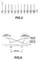
- Fig.6 schematically shows the manner of gain changes. That is, Fig.6 shows how the gain of 1/Huv(z) and the gain for 1/Hv(z) are changed during transition from the unvoiced (UV) portion to the voiced (V) portion.
- the coefficient for 1/Hv(z) is interpolated every 2.5 msec or every 20 samples, while the coefficient for 1/Huv(z) is 10 msec (80 samples) and 5 msec (40 samples) for the bit rates of 2 kbps and 6 kbps, respectively.
- waveform matching is done with the aid of the analysis by synthesis method by the second encoding unit 120 on the encoder side, so that interpolation can be done with the LSPs of the neighboring UV portion instead of with the equal interval LSPs.
- the zero input response is set to zero by clearing the internal state of the weighted synthesis filter 122 of 1/A(z) at the transition portion from V to UV.
- Outputs of these LPC synthesis filters 236, 237 are sent to independently provided post-filters 238v, 238u.
- post-filters 238v, 238u By post-filtering independently for V and UV, the intensity and frequency response of the post-filter are set to different values for V and UV.
- the windowing for the junction portion between the V and UV portions of the LPC residual signals, that is the excitation as an LPC synthesis filter input, is explained. This is performed by the sinusoidal synthesis circuit 215 of the voiced sound synthesis unit 211 and a windowing circuit 223 of the unvoiced sound synthesis unit 220.
- the noise synthesis and noise addition for the voiced (V) portion is explained. To this end, using the noise synthesis circuit 216, weighted overlap circuit 217 and the adder 218 of Fig.4, the noise taking into account the following parameters is added to the voiced portion of the LPC residual signals for the excitation which becomes the LPC filter input of the voiced portion.
- the processing by the noise synthesis circuit 216 is performed in a similar manner to the synthesis of the unvoiced sound for MBE.
- Fig.9 shows an illustrative example of the noise synthesis circuit 216.
- a Gaussian noise generator 401 there is outputted from a Gaussian noise generator 401 the Gaussian noise corresponding to the time-domain white noise signal waveform windowed to a pre-set length of, for example, 256 samples, by a suitable window function, such as a Hamming window.
- This output signal is transformed by short-term Fourier transform (STFT) by a STFT unit 402 to produce a noise power spectrum on the frequency axis.
- STFT short-term Fourier transform
- the power spectrum from the STFT unit 402 is sent to a multiplier 403 for amplitude processing where it is multiplied with an output of the noise amplitude control circuit 410.
- An output of the multiplier 403 is sent to an inverse STFT unit 404 so as to be inverse STFTed for conversion to the time-domain signal using the phase of the original white noise.
- An output of the ISTFT unit 404 is sent to the weighting overlap-add circuit 217 of Fig.4.
- the white noise generator 401 and the STFT unit 402 it is also possible to generate random numbers and to use them as real part or imaginary part or as the amplitude or phase of the white noise spectrum for processing, thereby omitting the STFT unit 402.
- the noise amplitude control circuit 410 has the basic structure as shown in Fig.10 and controls the multiplication coefficients of the multiplier 403, based on the spectral amplitude Am(i) for the voiced sound supplied from the dequantizer 212 for the spectral envelope shown in Fig.4 via terminal 411 and on the pitch lag Pch supplied from the input terminal 204 of Fig.4 via terminal 412, for finding the synthesized noise amplitude Am_ noise[i].
- f1(Pch,Am[i]) 0 (0 ⁇ i ⁇ Noise_ b ⁇ I)
- f1(Pch,Am[i]) Am[i] ⁇ noise_ mix (Noise_ b ⁇ I ⁇ i ⁇ 1).
- noise_ mix_ max The maximum value of noise_ mix is noise_ mix_ max, which is the clipping point.
- K 0.02
- noise_ mix_ max 0.3
- Noise_ b 0.7
- Noise_ b is a constant for determining in which partial portion of the entire area to begin to add the noise.
- noise amplitude Am_ noise[i] becomes three of the above four parameters, namely the pitch lag Pch, spectral amplitude Am[i] and the function f2(Pch,Am[i],Amax) of the maximum spectral amplitude Amax, is now explained.
- f2(Pch,Am[i],Amax) 0 (0 ⁇ i ⁇ Noise_ b ⁇ I)
- noise_ mix max the maximum value of noise_ mix.
- K 0.02
- noise_ mix_ max 0.3
- Noise_ b 0.7.
- An illustrative example of such function f3 (Pch,Am[i],Amax,Lev) is basically the same as the function f2(Pch,SAm[i],Amax) of the above second illustrative example.
- the residual signal level Lev is the root mean square (rms) of the spectral amplitude Am[i], or the signal level as measured on the time axis.
- the difference of the present example from the second illustrative example lies in setting the values of K and noise mix_ max as the functions of Lev. That is, if Lev becomes smaller, the values of L and noise_ mix_ max may be set to higher values, whereas, if Lev is larger, the values of L and noise_ mix_ max may be set to lower values.
- the value of Lev may be set so as to be continuously inversely proportionate to these values.
- the post-filters 238v, 238u will be explained.
- a spectral shaping filter 440 used as an essential portion of the post-filter, is made up of a formant stressing filter 441 and a high-range stressing filter 442.
- An output of the spectral shaping filter 440 is sent to a gain adjustment circuit 443 for correcting gain changes caused by spectral shaping.
- a gain G of the gain adjustment circuit 443 is set by a gain control circuit 445 which compares an input x and an output y of the spectral shaping filter 440 to calculate the gain change and a correction value.
- the characteristics PF(z)of the spectral shaping filter 440 is given by:
- the fractional part of the equation represents formant stressing characteristics while the portion (1 - kz -1 ) represents high range stressing filter characteristics.
- the gain G of the gain adjustment circuit 443 is given by: in which x(i) and y(i) are an input and an output of the spectral shaping filter 440, respectively.
- the updating period of the coefficient of the spectral shaping filter 440 is the same as the updating period of the ⁇ -parameter which is the LPC synthesis filter coefficient, that is 20 samples or 2.5 msec, whereas the updating period of the gain G of the gain adjustment circuit 443 is 160 samples or 20 msec.
- the updating period of the spectral shaping filter coefficient and the gain updating period are set so as to be equal to each other. If the gain updating period is 20 samples or 2.5 msec, variation occurs within a single pitch period, thus causing click noise. In the present embodiment, the gain switching period is set so as to be longer, that is equal to, for example, 160 samples for one frame, or 20 msec, for preventing gain variations from occurring. Conversely, if the updating period of the spectral shaping filter coefficient is longer, for example, 160 samples or 20 msec, post-filter characteristics cannot follow up with the short-term changes in the speech spectrum, such that the satisfactory psychoacoustic sound quality cannot be achieved. However, more effective post-filtering can be achieved by shortening the filter coefficient updating period to 20 samples or 2.5 msec,
- Fig.13 shows how the gain G1 of the previous frame is changed to the gain G2 of the current frame. That is, in the overlapping portion, the proportion of the gain and the filter coefficient of the previous frame is decreased gradually while the proportion of the gain and the filter coefficient of the current frame is increased gradually.
- both the filter of the current frame and the filter of the previous frame start from the same state, that is from the last state of the current frame.
- the above-described signal encoding and signal decoding apparatus may be used as a speech codebook employed in, for example, a portable communication terminal or a portable telephone set shown in Figs.14 and 15.
- Fig.14 shows a transmitting side of a portable terminal employing a speech encoding unit 160 configured as shown in Figs. 1 and 3.
- the speech signals collected by a microphone 161 are amplified by an amplifier 162 and converted by an analog/digital (A/D) converter 163 into digital signals which are sent to the speech encoding unit 160 configured as shown in Figs.1 and 3.
- the digital signals from the A/D converter 163 are supplied to the input terminal 101 of the encoding unit 160.
- the speech encoding unit 160 performs encoding as explained in connection with Figs.1 and 3.
- Output signals of output terminals of Figs.1 and 2 are sent as output signals of the speech encoding unit 160 to a transmission channel encoding unit 164 which then performs channel coding on the supplied signals.
- Output signals of the transmission channel encoding unit 164 are sent to a modulation circuit 165 for modulation and thence supplied to an antenna 168 via a digital/analog (D/A) converter 166 and an RF amplifier 167.
- D/A digital/analog
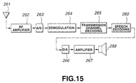
- Fig.15 shows a reception side of a portable terminal employing a speech decoding unit 260 configured as shown in Figs.2 and 4.
- the speech signals received by the antenna 261 of Fig.14 are amplified by an RF amplifier 262 and sent via an analog/digital (A/D) converter 263 to a demodulation circuit 264, from which demodulated signals are sent to a transmission channel decoding unit 265.
- An output signal of the decoding unit 265 is supplied to a speech decoding unit 260 configured as shown in Figs.2 and 4.
- the speech decoding unit 260 decodes the signals as explained in connection with Figs.2 and 4.
- An output signal at an output terminal 201 of Figs.2 and 4 is sent as a signal of the speech decoding unit 260 to a digital/analog (D/A) converter 266.
- An analog speech signals from the D/A converter 266 is sent to a speaker 268.
- the present invention as defined by the appended claims is not limited to the above-described embodiments.
- the structure of the speech analysis side (encoder side) of Figs.1 and 3 or the structure of the speech synthesis side (decoder side) of Figs.2 and 4 are described as hardware, these may also be implemented by a software program using a digital signal processor.
- an LPC synthesis filter or a post-filter may be used in common for the voiced speech and the unvoiced speech in place of providing the synthesis filters 236, 237 and the post-filters 238v, 238u as shown in Fig.4.
- the present invention may also be applied to a variety of usages, such as pitch conversion, speed conversion, computerized speech synthesis or noise suppression, instead of being limited to transmission or recording/reproduction.
Landscapes
- Engineering & Computer Science (AREA)
- Computational Linguistics (AREA)
- Signal Processing (AREA)
- Health & Medical Sciences (AREA)
- Audiology, Speech & Language Pathology (AREA)
- Human Computer Interaction (AREA)
- Physics & Mathematics (AREA)
- Acoustics & Sound (AREA)
- Multimedia (AREA)
- Compression, Expansion, Code Conversion, And Decoders (AREA)
Claims (9)
- Verfahren zur Sprachdecodierung, bei dem ein codiertes Sprachsignal geliefert, decodiert und anschließend nachgefiltert wird, wobei das Verfahren aufweist:dadurch gekennzeichnet, daß der Verstärkungsfaktor mit einer zweiten Periode aktualisiert wird, die länger ist als die erste Periode, mit der die Filterkoeffizienten aktualisiert werden.Durchführen einer Spektralformungsfilterung des decodierten gelieferten Signals, wobei Filterkoeffizienten verwendet werden, die periodisch aktualisiert werden; undDurchführung einer Verstärkungsfaktoreinstellung, wobei ein Verstärkungsfaktor verwendet wird, der periodisch zur Korrektur von Verstärkungsfaktoränderungen, die durch die Spektralformungsfilterung verursacht werden, aktualisiert wird,
- Verfahren zur Sprachdecodierung nach Anspruch 1, wobei der Verstärkungsfaktor durch Vergleichen des Signalpegels vor der Spektralformungsfilterung mit demjenigen im Anschluß an die Spektralformung eingestellt wird.
- Sprachdecodierverfahren nach einem der vorhergehenden Ansprüche, wobei die erste Periode 2,5ms beträgt.
- , Sprachdecodierverfahren nach einem der vorhergehenden Ansprüche, wobei die zweite Periode 20ms beträgt.
- Sprachdecodiergerät, bei dem ein codiertes Sprachsignal geliefert, decodiert und anschließend nachgefiltert wird, wobei das Gerät aufweist:dadurch gekennzeichnet, daß die Verstärkungsfaktor-Einstelleinrichtung eingerichtet ist, den Verstärkungsfaktor mit einer zweiten Periode zu aktualisieren, die länger ist als die erste Periode, mit der die Filterkoeffizienten aktualisiert werden.eine Spektralformungs-Filtereinrichtung (440) zum Spektralformen des decodierten gelieferten Signals mit einem Filterkoeffizienten, der periodisch aktualisiert wird; undeine Verstärkungsfaktor-Einstelleinrichtung (443, 445), der ein Ausgangssignal der Spektralformungs-Filtereinrichtung zugeführt wird und die eingerichtet ist, eine Verstärkungsfaktoreinstellung durchzuführen, um Verstärkungsfaktoränderungen, die durch die Spektralformungs-Filtereinrichtung verursacht werden, zu korrigieren, wobei ein Verstärkungsfaktor verwendet wird, der periodisch aktualisiert wird,
- Sprachdecodiergerät nach Anspruch 5, wobei der Verstärkungsfaktor durch Vergleich des Signalpegels vor der Spektralformungsfilterung mit dem in Anschluß an die Spektralformung eingestellt wird.
- Sprachdecodiergerät nach einem der Ansprüche 5 bis 6, wobei die erste Periode 2,5ms beträgt.
- Sprachdecodiergerät nach einem der Ansprüche 5 bis 7, wobei die zweite Periode 20ms beträgt.
- Tragbares Endgerät, welches aufweist:einen Verstärker (262) zum Verstärken eines Empfangssignals;eine Demodulationseinrichtung (263) zum A/D-Umsetzen und nachfolgendem Demodulieren des verstärkten Signals;eine Übertragungskanal-Decodiereinrichtung (265) zum Kanaldecodieren der demodulierten Signale; undeine Sprachdecodiereinrichtung (260) zum Decodieren eines Ausgangssignals der Übertragungskanal-Decodiereinrichtung, wobei die Sprachdecodiereinrichtung ein Sprachdecodiergerät gemäß einem der Ansprüche 5 bis 8 aufweist,eine D/A-Umsetzungseinrichtung (266) zum D/A-Umsetzen des decodierten Sprachsignals zum Erzeugen eines analogen Sprachsignals.
Applications Claiming Priority (4)
| Application Number | Priority Date | Filing Date | Title |
|---|---|---|---|
| JP27948995A JP3653826B2 (ja) | 1995-10-26 | 1995-10-26 | 音声復号化方法及び装置 |
| JP27948995 | 1995-10-26 | ||
| JP279489/95 | 1995-10-26 | ||
| US08/736,342 US5752222A (en) | 1995-10-26 | 1996-10-23 | Speech decoding method and apparatus |
Publications (3)
| Publication Number | Publication Date |
|---|---|
| EP0770988A2 EP0770988A2 (de) | 1997-05-02 |
| EP0770988A3 EP0770988A3 (de) | 1998-10-14 |
| EP0770988B1 true EP0770988B1 (de) | 2002-01-09 |
Family
ID=26553357
Family Applications (1)
| Application Number | Title | Priority Date | Filing Date |
|---|---|---|---|
| EP96307724A Expired - Lifetime EP0770988B1 (de) | 1995-10-26 | 1996-10-25 | Verfahren zur Sprachdekodierung und tragbares Endgerät |
Country Status (5)
| Country | Link |
|---|---|
| US (1) | US5752222A (de) |
| EP (1) | EP0770988B1 (de) |
| JP (1) | JP3653826B2 (de) |
| DE (1) | DE69618422T2 (de) |
| ES (1) | ES2165960T3 (de) |
Families Citing this family (37)
| Publication number | Priority date | Publication date | Assignee | Title |
|---|---|---|---|---|
| JP3707116B2 (ja) * | 1995-10-26 | 2005-10-19 | ソニー株式会社 | 音声復号化方法及び装置 |
| JP2940464B2 (ja) * | 1996-03-27 | 1999-08-25 | 日本電気株式会社 | 音声復号化装置 |
| JPH09319397A (ja) * | 1996-05-28 | 1997-12-12 | Sony Corp | ディジタル信号処理装置 |
| JP4040126B2 (ja) * | 1996-09-20 | 2008-01-30 | ソニー株式会社 | 音声復号化方法および装置 |
| JPH10105195A (ja) * | 1996-09-27 | 1998-04-24 | Sony Corp | ピッチ検出方法、音声信号符号化方法および装置 |
| JP4121578B2 (ja) * | 1996-10-18 | 2008-07-23 | ソニー株式会社 | 音声分析方法、音声符号化方法および装置 |
| JP3164038B2 (ja) * | 1997-11-05 | 2001-05-08 | 日本電気株式会社 | 音声帯域分割復号装置 |
| KR100429180B1 (ko) * | 1998-08-08 | 2004-06-16 | 엘지전자 주식회사 | 음성 패킷의 파라미터 특성을 이용한 오류 검사 방법 |
| KR20000047944A (ko) * | 1998-12-11 | 2000-07-25 | 이데이 노부유끼 | 수신장치 및 방법과 통신장치 및 방법 |
| JP2000305599A (ja) * | 1999-04-22 | 2000-11-02 | Sony Corp | 音声合成装置及び方法、電話装置並びにプログラム提供媒体 |
| FR2796190B1 (fr) * | 1999-07-05 | 2002-05-03 | Matra Nortel Communications | Procede et dispositif de codage audio |
| EP1796083B1 (de) * | 2000-04-24 | 2009-01-07 | Qualcomm Incorporated | Verfahren und Vorrichtung zur prädiktiven Quantisierung von stimmhaften Sprachsignalen |
| US6941263B2 (en) * | 2001-06-29 | 2005-09-06 | Microsoft Corporation | Frequency domain postfiltering for quality enhancement of coded speech |
| US7110942B2 (en) * | 2001-08-14 | 2006-09-19 | Broadcom Corporation | Efficient excitation quantization in a noise feedback coding system using correlation techniques |
| US7353168B2 (en) * | 2001-10-03 | 2008-04-01 | Broadcom Corporation | Method and apparatus to eliminate discontinuities in adaptively filtered signals |
| US7206740B2 (en) * | 2002-01-04 | 2007-04-17 | Broadcom Corporation | Efficient excitation quantization in noise feedback coding with general noise shaping |
| US7065485B1 (en) * | 2002-01-09 | 2006-06-20 | At&T Corp | Enhancing speech intelligibility using variable-rate time-scale modification |
| US20030135374A1 (en) * | 2002-01-16 | 2003-07-17 | Hardwick John C. | Speech synthesizer |
| US7328151B2 (en) * | 2002-03-22 | 2008-02-05 | Sound Id | Audio decoder with dynamic adjustment of signal modification |
| JP3881943B2 (ja) | 2002-09-06 | 2007-02-14 | 松下電器産業株式会社 | 音響符号化装置及び音響符号化方法 |
| AU2003208517A1 (en) * | 2003-03-11 | 2004-09-30 | Nokia Corporation | Switching between coding schemes |
| SE0301272D0 (sv) * | 2003-04-30 | 2003-04-30 | Coding Technologies Sweden Ab | Adaptive voice enhancement for low bit rate audio coding |
| US7844451B2 (en) | 2003-09-16 | 2010-11-30 | Panasonic Corporation | Spectrum coding/decoding apparatus and method for reducing distortion of two band spectrums |
| CN1989548B (zh) * | 2004-07-20 | 2010-12-08 | 松下电器产业株式会社 | 语音解码装置及补偿帧生成方法 |
| KR100644627B1 (ko) * | 2004-09-14 | 2006-11-10 | 삼성전자주식회사 | 음장 제어 정보 부호화 방법 및 이에 적합한 음장 처리 방법 |
| US7590523B2 (en) * | 2006-03-20 | 2009-09-15 | Mindspeed Technologies, Inc. | Speech post-processing using MDCT coefficients |
| US8335684B2 (en) * | 2006-07-12 | 2012-12-18 | Broadcom Corporation | Interchangeable noise feedback coding and code excited linear prediction encoders |
| US20100332223A1 (en) | 2006-12-13 | 2010-12-30 | Panasonic Corporation | Audio decoding device and power adjusting method |
| EP2101322B1 (de) * | 2006-12-15 | 2018-02-21 | III Holdings 12, LLC | Codierungseinrichtung, decodierungseinrichtung und verfahren dafür |
| CN101303858B (zh) * | 2007-05-11 | 2011-06-01 | 华为技术有限公司 | 实现基音增强后处理的方法及装置 |
| EP2466580A1 (de) * | 2010-12-14 | 2012-06-20 | Fraunhofer-Gesellschaft zur Förderung der Angewandten Forschung e.V. | Codierer und Verfahren zur prädiktiven Codierung, Decodierer und Verfahren zur Decodierung, System und Verfahren zur prädiktiven Codierung und Decodierung und prädiktiv codiertes Informationssignal |
| FR2969805A1 (fr) * | 2010-12-23 | 2012-06-29 | France Telecom | Codage bas retard alternant codage predictif et codage par transformee |
| KR102060208B1 (ko) * | 2011-07-29 | 2019-12-27 | 디티에스 엘엘씨 | 적응적 음성 명료도 처리기 |
| FR3023646A1 (fr) * | 2014-07-11 | 2016-01-15 | Orange | Mise a jour des etats d'un post-traitement a une frequence d'echantillonnage variable selon la trame |
| EP2980796A1 (de) | 2014-07-28 | 2016-02-03 | Fraunhofer-Gesellschaft zur Förderung der angewandten Forschung e.V. | Verfahren und Vorrichtung zur Verarbeitung eines Audiosignals, Audiodecodierer und Audiocodierer |
| EP2980799A1 (de) | 2014-07-28 | 2016-02-03 | Fraunhofer-Gesellschaft zur Förderung der angewandten Forschung e.V. | Vorrichtung und Verfahren zur Verarbeitung eines Audiosignals mit Verwendung einer harmonischen Nachfilterung |
| CN116168719A (zh) * | 2022-12-26 | 2023-05-26 | 杭州爱听科技有限公司 | 一种基于语境分析的声音增益调节方法及系统 |
Family Cites Families (5)
| Publication number | Priority date | Publication date | Assignee | Title |
|---|---|---|---|---|
| US5307441A (en) * | 1989-11-29 | 1994-04-26 | Comsat Corporation | Wear-toll quality 4.8 kbps speech codec |
| US5233660A (en) * | 1991-09-10 | 1993-08-03 | At&T Bell Laboratories | Method and apparatus for low-delay celp speech coding and decoding |
| US5339384A (en) * | 1992-02-18 | 1994-08-16 | At&T Bell Laboratories | Code-excited linear predictive coding with low delay for speech or audio signals |
| US5574825A (en) * | 1994-03-14 | 1996-11-12 | Lucent Technologies Inc. | Linear prediction coefficient generation during frame erasure or packet loss |
| US5664055A (en) * | 1995-06-07 | 1997-09-02 | Lucent Technologies Inc. | CS-ACELP speech compression system with adaptive pitch prediction filter gain based on a measure of periodicity |
-
1995
- 1995-10-26 JP JP27948995A patent/JP3653826B2/ja not_active Expired - Fee Related
-
1996
- 1996-10-23 US US08/736,342 patent/US5752222A/en not_active Expired - Lifetime
- 1996-10-25 EP EP96307724A patent/EP0770988B1/de not_active Expired - Lifetime
- 1996-10-25 ES ES96307724T patent/ES2165960T3/es not_active Expired - Lifetime
- 1996-10-25 DE DE69618422T patent/DE69618422T2/de not_active Expired - Lifetime
Also Published As
| Publication number | Publication date |
|---|---|
| US5752222A (en) | 1998-05-12 |
| JP3653826B2 (ja) | 2005-06-02 |
| EP0770988A2 (de) | 1997-05-02 |
| DE69618422D1 (de) | 2002-02-14 |
| DE69618422T2 (de) | 2002-08-29 |
| EP0770988A3 (de) | 1998-10-14 |
| JPH09127996A (ja) | 1997-05-16 |
| ES2165960T3 (es) | 2002-04-01 |
Similar Documents
| Publication | Publication Date | Title |
|---|---|---|
| EP0770988B1 (de) | Verfahren zur Sprachdekodierung und tragbares Endgerät | |
| EP0770987B1 (de) | Verfahren und Vorrichtung zur Wiedergabe von Sprachsignalen, zur Dekodierung, zur Sprachsynthese und tragbares Funkendgerät | |
| JP3566652B2 (ja) | 広帯域信号の効率的な符号化のための聴覚重み付け装置および方法 | |
| JP4662673B2 (ja) | 広帯域音声及びオーディオ信号復号器における利得平滑化 | |
| CA2188493C (en) | Speech encoding/decoding method and apparatus using lpc residuals | |
| EP0837453B1 (de) | Verfahren zur Sprachanalyse sowie Verfahren und Vorrichtung zur Sprachkodierung | |
| KR100421226B1 (ko) | 음성 주파수 신호의 선형예측 분석 코딩 및 디코딩방법과 그 응용 | |
| US6334105B1 (en) | Multimode speech encoder and decoder apparatuses | |
| RU2255380C2 (ru) | Способ и устройство воспроизведения речевых сигналов и способ их передачи | |
| US5778335A (en) | Method and apparatus for efficient multiband celp wideband speech and music coding and decoding | |
| US6047253A (en) | Method and apparatus for encoding/decoding voiced speech based on pitch intensity of input speech signal | |
| EP0843302A2 (de) | Sprachkodierer mit Sinusanalyse und Grundfrequenzsteuerung | |
| GB2342829A (en) | Postfilter | |
| US6012023A (en) | Pitch detection method and apparatus uses voiced/unvoiced decision in a frame other than the current frame of a speech signal | |
| KR100421816B1 (ko) | 음성복호화방법 및 휴대용 단말장치 | |
| JP4826580B2 (ja) | 音声信号の再生方法及び装置 | |
| JP3896654B2 (ja) | 音声信号区間検出方法及び装置 | |
| JP4230550B2 (ja) | 音声符号化方法及び装置、並びに音声復号化方法及び装置 | |
| EP1164577A2 (de) | Verfahren und Einrichtung zur Wiedergabe von Sprachsignalen |
Legal Events
| Date | Code | Title | Description |
|---|---|---|---|
| PUAI | Public reference made under article 153(3) epc to a published international application that has entered the european phase |
Free format text: ORIGINAL CODE: 0009012 |
|
| AK | Designated contracting states |
Kind code of ref document: A2 Designated state(s): DE ES FR GB NL |
|
| PUAL | Search report despatched |
Free format text: ORIGINAL CODE: 0009013 |
|
| AK | Designated contracting states |
Kind code of ref document: A3 Designated state(s): DE ES FR GB NL |
|
| 17P | Request for examination filed |
Effective date: 19990323 |
|
| GRAG | Despatch of communication of intention to grant |
Free format text: ORIGINAL CODE: EPIDOS AGRA |
|
| RIC1 | Information provided on ipc code assigned before grant |
Free format text: 7G 10L 19/14 A |
|
| 17Q | First examination report despatched |
Effective date: 20010323 |
|
| GRAG | Despatch of communication of intention to grant |
Free format text: ORIGINAL CODE: EPIDOS AGRA |
|
| GRAH | Despatch of communication of intention to grant a patent |
Free format text: ORIGINAL CODE: EPIDOS IGRA |
|
| GRAH | Despatch of communication of intention to grant a patent |
Free format text: ORIGINAL CODE: EPIDOS IGRA |
|
| GRAA | (expected) grant |
Free format text: ORIGINAL CODE: 0009210 |
|
| REG | Reference to a national code |
Ref country code: GB Ref legal event code: IF02 |
|
| AK | Designated contracting states |
Kind code of ref document: B1 Designated state(s): DE ES FR GB NL |
|
| REF | Corresponds to: |
Ref document number: 69618422 Country of ref document: DE Date of ref document: 20020214 |
|
| REG | Reference to a national code |
Ref country code: ES Ref legal event code: FG2A Ref document number: 2165960 Country of ref document: ES Kind code of ref document: T3 |
|
| ET | Fr: translation filed | ||
| PLBE | No opposition filed within time limit |
Free format text: ORIGINAL CODE: 0009261 |
|
| STAA | Information on the status of an ep patent application or granted ep patent |
Free format text: STATUS: NO OPPOSITION FILED WITHIN TIME LIMIT |
|
| 26N | No opposition filed | ||
| REG | Reference to a national code |
Ref country code: GB Ref legal event code: 746 Effective date: 20120703 |
|
| REG | Reference to a national code |
Ref country code: DE Ref legal event code: R084 Ref document number: 69618422 Country of ref document: DE Effective date: 20120614 |
|
| PGFP | Annual fee paid to national office [announced via postgrant information from national office to epo] |
Ref country code: ES Payment date: 20141020 Year of fee payment: 19 Ref country code: DE Payment date: 20141022 Year of fee payment: 19 Ref country code: GB Payment date: 20141021 Year of fee payment: 19 Ref country code: FR Payment date: 20141022 Year of fee payment: 19 |
|
| PGFP | Annual fee paid to national office [announced via postgrant information from national office to epo] |
Ref country code: NL Payment date: 20151021 Year of fee payment: 20 |
|
| REG | Reference to a national code |
Ref country code: DE Ref legal event code: R119 Ref document number: 69618422 Country of ref document: DE |
|
| GBPC | Gb: european patent ceased through non-payment of renewal fee |
Effective date: 20151025 |
|
| PG25 | Lapsed in a contracting state [announced via postgrant information from national office to epo] |
Ref country code: GB Free format text: LAPSE BECAUSE OF NON-PAYMENT OF DUE FEES Effective date: 20151025 Ref country code: DE Free format text: LAPSE BECAUSE OF NON-PAYMENT OF DUE FEES Effective date: 20160503 |
|
| REG | Reference to a national code |
Ref country code: FR Ref legal event code: ST Effective date: 20160630 |
|
| PG25 | Lapsed in a contracting state [announced via postgrant information from national office to epo] |
Ref country code: FR Free format text: LAPSE BECAUSE OF NON-PAYMENT OF DUE FEES Effective date: 20151102 |
|
| REG | Reference to a national code |
Ref country code: NL Ref legal event code: MK Effective date: 20161024 |
|
| REG | Reference to a national code |
Ref country code: ES Ref legal event code: FD2A Effective date: 20161128 |
|
| PG25 | Lapsed in a contracting state [announced via postgrant information from national office to epo] |
Ref country code: ES Free format text: LAPSE BECAUSE OF NON-PAYMENT OF DUE FEES Effective date: 20151026 |