EP0770912A2 - System for controlling circulation of developing liquid - Google Patents
System for controlling circulation of developing liquid Download PDFInfo
- Publication number
- EP0770912A2 EP0770912A2 EP96116929A EP96116929A EP0770912A2 EP 0770912 A2 EP0770912 A2 EP 0770912A2 EP 96116929 A EP96116929 A EP 96116929A EP 96116929 A EP96116929 A EP 96116929A EP 0770912 A2 EP0770912 A2 EP 0770912A2
- Authority
- EP
- European Patent Office
- Prior art keywords
- use condition
- processing
- tank
- circulating pump
- circulation
- Prior art date
- Legal status (The legal status is an assumption and is not a legal conclusion. Google has not performed a legal analysis and makes no representation as to the accuracy of the status listed.)
- Granted
Links
Images


Classifications
-
- G—PHYSICS
- G03—PHOTOGRAPHY; CINEMATOGRAPHY; ANALOGOUS TECHNIQUES USING WAVES OTHER THAN OPTICAL WAVES; ELECTROGRAPHY; HOLOGRAPHY
- G03D—APPARATUS FOR PROCESSING EXPOSED PHOTOGRAPHIC MATERIALS; ACCESSORIES THEREFOR
- G03D3/00—Liquid processing apparatus involving immersion; Washing apparatus involving immersion
- G03D3/02—Details of liquid circulation
- G03D3/06—Liquid supply; Liquid circulation outside tanks
Landscapes
- Physics & Mathematics (AREA)
- General Physics & Mathematics (AREA)
- Photographic Processing Devices Using Wet Methods (AREA)
Abstract
Description
- The present invention relates to a system for controlling circulation of developing liquid, which includes a processing tank holding therein developing liquid for developing photosensitive material, an auxiliary tank communicated with an upper region of the developing tank, a circulating passage communicating between the auxiliary tank and a lower region of the processing tank, and a circulating pump for providing circulation of the developing liquid from the upper region of the processing tank through the auxiliary tank, the circulating passage, the lower region of the processing tank then back to the upper region of the processing tank.
- A photographic developing device for developing photosensitive material such as a photographic film or a print paper includes a processing tank in which processing liquid is held. As the photosensitive material is caused to travel through the liquid, chemical reaction takes place between the processing liquid and the material, whereby the material is photographically developed. In the course of this, in order to promote the chemical reaction between the processing liquid and the photosensitive material, positive circulation flow of the liquid is generated so as to increase the opportunity of contact between the material and fresher, i.e. un-fatigued processing liquid. This liquid flow is generated by using a circulating pump which creates forced circulation of the processing liquid from an upper region of the processing tank through the auxiliary tank, the circulating passage, the lower region of the processing tank and again to the upper region of the processing tank. Also, in the course of this circulation, replenishing, i.e. fresh processing liquid is supplied from the auxiliary tank into the circulating passage.
- However, the generation of such strong pump-forced circulation necessarily causes stirring of the processing liquid, thereby to increase the opportunity of contact between air present adjacent the surface of the liquid and this processing liquid which tends to deteriorate by oxidation. Therefore, such forceful circulation arrangement has been disadvantageous in that it tends to accelerate oxidation deterioration of the processing liquid.
- A primary object of the present invention is to provide an improved system for controlling circulation of processing liquid having the two contradictory effects of promoting reaction between processing liquid and photosensitive material and of accelerating of oxidation deterioration of the processing liquid.
- For accomplishing the above-noted object, in the developing liquid circulation controlling system described at the onset, the system according to the present invention comprises: use condition detecting means for detecting at least two differing use conditions of the processing tank including first and second use conditions; and controlling means operatively connected with both the circulating pump and the use condition detecting means for setting the circulating pump to a high circulation amount mode when the use condition detecting means detects the first use condition and alternatively setting the circulating pump to a low circulation amount mode when the use condition detecting means detects the second use condition.
- The above controlling system attends to the facts that there exist at least two differing conditions of the processing tank, i.e. one condition (the 'first use condition') in which positive circulation of the processing liquid should be generated within the tank and the other condition (the 'second use condition') in which such positive circulation is not always necessary or desirable. Then, when the positive circulation of the processing liquid is needed, particularly when photosensitive material is present within the processing tank, the circulating pump is set to the high circulation amount mode so as to promote reaction between the processing liquid and the photosensitive material. Whereas, when such positive circulation is not needed or needed only by a very limited degree, the pump is set to the low circulation amount mode so as to minimize oxidation deterioration of the processing liquid.
- In comparison with the conventional system in which the circulation pump is constantly operated at a fixed circulation amount, the above-described system of the invention provides the advantage of restricting oxidation deterioration of processing liquid while achieving the same effect of promoting the development reaction between the liquid and the photosensitive material.
- According to one aspect of the invention, the use condition detecting means detects presence of the photosensitive material within the processing tank as the first use condition and detects absence of the photosensitive material within the processing tank as the second use condition. With this, the photosensitive material introduced into the processing tank may be subjected to an enhanced development reaction by the positive circulation of the processing liquid. On the other hand, when no photosensitive material is present within the tank, the oxidation deterioration of the processing liquid is restricted advantageously due to absence of strong circulation thereof while a minimum necessary amount of fresh liquid may be replenished via the circulating passage.
- According to a further aspect of the present invention, the use condition detecting means includes an entrance detecting sensor for detecting of entrance the photosensitive material into the processing tank and a timer for measuring an estimated time period until the introduced photosensitive material is estimated to leave the processing tank. With this construction, entrance of the photosensitive material is detected by the entrance detecting sensor which may be embodied either as a non-contact type sensor such as an optical sensor or as a contact type sensor such as a limit switch. Upon this detection, the circulating pump is geared into the high circulation amount mode. Also, the timer calculates the estimated time period until estimated exit of the photosensitive material from the tank, thereby to determine the timing at which the circulating pump is switched over from the high circulation amount mode to the low circulation amount mode.
- A still further aspect of the present invention suggests that the circulating pump under the high circulation amount mode provides an output about twice greater than that under the low circulation amount mode. With this setting, it is possible to obtain optimum balance among the promotion of reaction of the photosensitive material, the restriction of oxidation deterioration of the processing liquid and minimum yet effective supply of replenishing liquid.
- For developing the photosensitive material, there are generally needed a plurality of kinds of processing liquid exemplified by developing liquid, bleaching liquid, fixing liquid, and stabilizing liquid. And, these kinds of liquid are held separately within a plurality of processing chambers formed within the processing tank. Then, the photosensitive material is caused to pass through these chambers one after another. Therefore, in this type of developing apparatus, the circulating pump is to be provided for each kind of processing liquid. Then, the control consideration concerning whether the pump is operated under the high circulation amount mode or the low circulation amount mode should be made in accordance with a signal from the use condition detecting means for detecting at least two differing use conditions of each processing chamber.
- Preferably, the first and second use conditions based on which each circulating pump is controlled relate respectively to presence and absence of the photosensitive material within each processing tank. In this, if the use condition detecting means includes an entrance detecting sensor for detecting entrance of the photosensitive material into the first one of the processing chambers for first processing the photosenstive material and a timer for measuring estimated time periods spanning from entrance to exit of the photosenstive material to and from the respective processing chambers; then, the presence/absence of the photosensitive material within each processing chamber may be determined by means of the single entrance detecting sensor and the single timer. So that, the construction of the control system may be made simple advantageously.
- Further and other objects, features and effects of the invention will become more apparent from the following more detailed description of the embodiments of the invention with reference to the accompanying drawings.
-
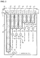
- Fig. 1 is an overall construction view of an automatic film developing apparatus employing a developing liquid circulation controlling system relating to one preferred embodiment of the present invention,
- Fig. 2 is a schematic section view of a film developing section of the automatic film developing apparatus of Fig. 1,
- Fig. 3 is a schematic section view of a development processing tank,
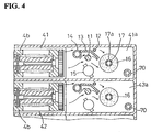
- Fig. 4 is a section view taken along a line IV-IV in Fig. 3,
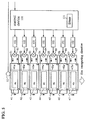
- Fig. 5 is a block diagram of the developing liquid circulation controlling system according to the embodiment, and
- Fig. 6 is a schematic timing chart relating to the controlling system.
- Next, preferred embodiments of the present invention relating to an automatic
film developing apparatus 1 will be described with reference to the accompanying drawings. - As shown in Fig. 1, the automatic
film developing apparatus 1 includes afilm loading section 3 for loading a film 3 (an example of photosensitive material) with a leader connected to a leading end thereof, a film developing section 4 for developing thefilm 2 fed from thefilm loading section 3, afilm drying section 5 for drying thedeveloped film 2, and afilm receiver section 6 for temporarily holding thefilm 2 after its drying operation. - The
film loading section 3 includes a transport roller 3a, a film cutter 3b for cutting off a trailing end of thefilm 2 which has been entirely withdrawn from afilm patrone 7, a film cutting solenoid 3c for slidably driving one of paired cutter blades of the film cutter 3b, a free roller 3e operable, under a pressing state thereof, to press thefilm 2 against the transport roller 3a, and apressing solenoid 3d for switching over the free roller 3e between the pressing state and a non-pressing state by vertically moving this roller 3e. Thefilm 2 entirely withdrawn from and cut off thepatrone 7 is transported as being pinched between the transport roller 3a and the free roller 3e to be introduced into the film developing section 4. - The film developing section 4 includes a
processing tank 40 having total 7 (seven) separate chambers for individually holding therein a plurality of kinds of processing liquid such as developing liquid, bleaching liquid, fixing liquid, stabilizing liquid and so on for effecting a series of processing steps such as development, bleaching, fixation and so on. The developing section 4 also includes a plurality oftransport roller units 4b for transporting thefilm 2 within this developing section 4. - The
film drying section 5 disposed at a downstream position in a film transport passage relative to the film developing section 4 includes a drying heater 5a for drying thefilm 2, adrying fan 5b for supplying hot air to the film transport passage and atemperature sensor 5c for detecting the temperature inside thefilm drying section 5. So that, through thisfilm drying section 5, thefilm 2 is transported while being dried gradually. Then, this driedfilm 2 is discharged to thefilm receiver section 6. - Fig. 2 shows only the film developing section 4 in details. An
optical sensor 10 is disposed adjacent an entrance opening of the film developing section 4 for detecting entrance of thefilm 2 from thefilm loading section 3. Thisoptical sensor 10 is connected to acontrol device 100 to be detailed later. As described hereinbefore, theprocessing tank 40 includes the sevenprocessing chambers 41 through 47. Specifically, seen from the entrance direction of thefilm 2, first is provided the developingliquid chamber 41 having the greatest depth of all the chambers, and then are provided one bleachingliquid chamber 42 and twofixing liquid chambers chamber 41. Thereafter, three stabilizing liquid chambers 45-47 are provided which are the shallowest of all. Except differing in the depths, these chambers 41-47 are constructed otherwise identical. Fig. 3 shows a vertical section of the developingliquid chamber 41 and Fig. 4 shows a horizontal section of thesame chamber 41 and of the bleachingliquid chamber 42, respectively. - The developing
chamber 41 includes, beside an upper region thereof, anauxiliary tank 41a, with the upper region of thechamber 41 and theauxiliary tank 41a being communicated with each other. Theauxiliary tank 41a is communicated also with a bottom of thechamber 41 via a circulatingpassage 51 which incorporates therein a circulatingpump 61. Inside theauxiliary tank 41a, there are provided aheater 11 for heating the developing liquid, atemperature sensor 12 for detecting temperature of the developing liquid, apartition plate 13 interposed between theheater 11 and thetemperature sensor 12, anoverflow pipe 14, aliquid level sensor 15 for detecting the level of the developing liquid, and afilter 16. Theheater 11 is controlled so as to maintain the temperature of the developing liquid constant by a feed-back control scheme using thetemperature sensor 12. As schematically shown in Figs. 2 and 3, theauxiliary tank 41a is connected with a replenishingpipe 70. Then, in order to maintain constant the developing performance of the developing liquid, a replenishingpump 71 is operated when necessary to replenish additional fresh developing liquid via thepipe 70 from a replenishingtank 72. - The
filter 16 is a cylindrical filter having a central bore into which apipe 17 defining a number slits 17a is inserted. In operation, filtered liquid flows through theseslits 17a into thepipe 17. Further, a lower end of thispipe 17 is communicated with the circulatingpassage 51. As a result, there is formed a circulation looped line from the upper region of the developingliquid chamber 41, theauxiliary tank 41a, thefilter 16, the circulatingpassage 51 incorporating the circulatingpump 61, the bottom region of the developingliquid chamber 41 and then back to the upper region of the same, whereby the developing liquid is circulated inside this developingliquid chamber 41. These constructions relating to the auxiliary tank and circulation line are identical for the other chambers also. Hence, the constructions of other chambers will not be described repeatedly. - The amount of liquid circulation within the chamber is determined generally by the operational capacity of the circulating pump. In the instant embodiment, the circulating pump is constructed as a variable output type which allows switching-over of its output between two high and low steps under the control of the
control device 100. Fig. 5 is a diagram of this circulation amount control system. As may be apparent from this figure, the respective chambers 41-47 and their correspondingauxiliary tanks 41a-47a are communicated with each other via respective circulating passages 51-57. And, these circulating passages 51-57 incorporate first through seventh circulating pumps 61-67, respectively. These circulating pumps 61-67 are switched over between the two steps of high and low output states viarespective pump drivers 102 by thecontrol device 100. That is, thecontrol device 100 and thepump drivers 102 together constitute circulation amount controlling means using the circulating pumps 61-67. - In the present embodiment, the high/low two step switchover of the circulating pump is effected in such a manner that the pump is operated under the high circulation amount mode in the case of a first use condition where a film to be processed is present within the corresponding chamber and the pump is operated under the low circulation amount mode in the case of a second use condition where a film to be processed is not present within the corresponding chamber. The detection of these two distinct conditions is made by the
control device 100 using atimer 101. Thistimer 101 calculates a time period in which the film is expected to stay within the respective chamber, based on a detection signal from theoptical sensor 10 constituting a use condition detecting means, with the time period being calculated from the moment of receiving this detection signal. - More particularly, as may be clearly understood from a timing chart of Fig. 6, first, upon lapse of an estimated time period t1 spanning from reception from the
optical sensor 10 of the signal indicating the detection of thefilm 2 to transport of thefilm 2 from the position of theoptical sensor 10 to the developingliquid chamber 41, a first timer for the first circulatingpump 61 is started. Synchronously with this start of the first timer, a high output control signal for the first circulatingpump 61 is transmitted to thedriver 102, such that the first circulatingpump 61 is geared into the high circulation amount mode to render thechamber 41 into a high liquid circulation condition. Next, upon lapse of an estimated time period t2 spanning from the departure of thefilm 2 from the position of theoptical sensor 10 to expected arrivial thereof at the second chamber, i.e. bleachingliquid chamber 42, a second timer for the second circulatingpump 62 is started. Synchronously with this start of the second timer, a high output control signal for the second circulatingpump 62 is transmitted to itscorresponding driver 102, such that the second circulatingpump 62 is geared into the high circulation amount mode to render thechamber 42 into the high liquid circulation condition. With lapse of an estimated time period t11 spanning from the entrance of the leading end of thefilm 2 into thechamber 41 and expected exit of the trailing end of thefilm 2 from thechamber 41, the first timer times up, upon which timing the high output control signal to the first circulatingpump 61 is terminated and a low output control signal instead is outputted to thedriver 102, thereby to render thechamber 42 into a low liquid circulation condition. The other circulating pumps 63-67 are operated in the same manner as described above. Therefore, for avoiding redundancy, the timing chart of Fig. 6 shows timing control of the first and second circulating pumps only. - In the manner described above, with entrance of the
film 2 into each chamber, the corresponding circulating pump is switched over from the low circulation output mode to the high circulation output mode, whereby the chamber is operated under the high liquid circulation condition. Also, with exit of thefilm 2 from the chamber, the circulating pump is switched over from the high circulation amount mode to the low circulation amount mode, whereby the chamber is operated under the low liquid circulation condition. - The high circulation amount and low circulation amount may vary, depending on such factors as the capacity of the
processing tank 40, or any other processing condition. Yet, it has been experimentally confirmed that if such factor as uniformity of the quality of the developing liquid is to be considered, then, in general the high circulation amount should correspond to the usual circulation amount for effecting a devloping operation and the low circulation amount should correspond to about a half of this high circulation amount. In any case, in comparison with the conventional system which constantly operates at the high circulation amount condition, the invention's system, which selectively provides the low circulation amount mode when needed, provides the advantage of restricting oxidiation deterioration of the processing liquid. - The timer is provided in the form of a software stored in a microcomputer constituting the
control device 100, so that the estimated time periods described above are adjustable in order to cope with differences in the film length, film transport speed and the like. Moreover, thecontrol device 100 has a switch for dummy or manual forced setting of either the first use condition or the second use condition regardless of the presence/absence of a film inside a chamber, so as to allow a desired chamber to be circulated at the high or low circulation amount condition for a desired period of time. - In the foregoing embodiment, the presence/absence of a film within a chamber is determined based on a detection signal from the optical sensor for detectig entrance of a film into the
processing tank 40 and the expected time period measured thereafter until the exit of the film therefrom. Instead, it is also within the scope of the present invention to provide a film detecting sensor for each chamber. - Further, in the foregoing embodiment, the high/low circulation amount switch-over is effected for each and every circulating pump. Instead, this switch-over may be effected for only one or some of the circulating pumps as needed.
- The invention may be embodied in other specific forms without departing from the spirit or essential characteristics thereof. The present embodiments are therefore to be considered in all respects as illustrative and not restrictive, the scope of the invention being indicated by the appended claims rather than the foregoing description and all changes which come within the meaning and range of equivalency of the claims are therefore intended to be embraced therein.
Claims (7)
- A system for controlling circulation of developing liquid, which includes a processing tank storing therein developing liquid for developing photosensitive material, an auxiliary tank communicated with an upper region of the developing tank, a circulating passage communicating between the auxiliary tank and a lower region of the processing tank, and a circulating pump for generating circulation of the developing liquid from the upper region of the processing tank through the auxiliary tank, the circulating passage, the lower region of the processing tank then back to the upper region of the processing tank,
characterized in thatthe circulating pump is capable of creating at least two selectable differing circulation amounts; andthe system includes use condition detecting means for detecting at least two use differing conditions of the processing tank including first and second use conditions; and controlling means operatively connected with the circulating pump and the use condition detecting means for setting the circulating pump to a high circulation amount mode when the use condition detecting means detects the first use condition and alternatively setting the circulating pump to a low circulation amount mode when the use condition detecting means detects the second use condition. - A system according to claim 1,
characterized in thatthe use condition detecting means detects presence of the photosensitive material within the processing tank as the first use condition and detects absence of the photosensitive material within the processing tank as the second use condition. - A system according to claim 2,
characterized in thatthe use condition detecting means includes an entrance detecting sensor for detecting of entrance of the photosensitive material into the processing tank and a timer for measuring an estimated time period until the introduced photosensitive material is expected to leave the processing tank. - A system according to any one of claims 1 through 3,
characterized in thatsaid high circulation amount is substantially twice greater than said low circulation amount. - A system for controlling circulation of developing liquid, having:a tank unit including a plurality of processing chambers for individually holding therein a plurality of kinds of processing liquid for serially processing photosensitive material for developing the material;a plurality of auxiliary tanks provided in correspondence with the processing chambers, each auxiliary tank being communicated with an upper region of the corresponding processing chamber;a circulating passage communicating between the auxiliary tank and a lower region of the processing chamber;a circulating pump for generating circulation of the developing liquid from the upper region of the processing chamber through the auxiliary tank, the circulating passage, the lower region of the processing tank then back to the upper region of the processing tank;
characterized in thatthe circulating pump is capable of creating at least two selectable differing circulation amounts; andthe system includes use condition detecting means for detecting at least two use differing conditions of the processing chamber including first and second use conditions; and controlling means operatively connected with the circulating pump and the use condition detecting means for setting the circulating pump to a high circulation amount mode when the use condition detecting means detects the first use condition and alternatively setting the circulating pump to a low circulation amount mode when the use condition detecting means detects the second use condition. - A system according to claim 5,
characterized in thatthe use condition detecting means detects presence of the photosensitive material within the processing chamber as the first use condition and detects absence of the photosensitive material within the processing chamber as the second use condition. - A system according to claim 6,
characterized in thatthe use condition detecting means includes an entrance detecting sensor for detecting of entrance of the photosensitive material into the first one of the processing chambers for first processing the photosensitive material, and a timer for measuring estimated time periods spanning from entrance to exit of the photosenstive material to and from the respective processing chambers.
Applications Claiming Priority (3)
| Application Number | Priority Date | Filing Date | Title |
|---|---|---|---|
| JP277799/95 | 1995-10-25 | ||
| JP27779995 | 1995-10-25 | ||
| JP7277799A JP3006707B2 (en) | 1995-10-25 | 1995-10-25 | Developing solution circulation control system |
Publications (3)
| Publication Number | Publication Date |
|---|---|
| EP0770912A2 true EP0770912A2 (en) | 1997-05-02 |
| EP0770912A3 EP0770912A3 (en) | 1997-12-10 |
| EP0770912B1 EP0770912B1 (en) | 2004-01-02 |
Family
ID=17588447
Family Applications (1)
| Application Number | Title | Priority Date | Filing Date |
|---|---|---|---|
| EP96116929A Expired - Lifetime EP0770912B1 (en) | 1995-10-25 | 1996-10-22 | System for controlling circulation of developing liquid |
Country Status (4)
| Country | Link |
|---|---|
| US (1) | US5852755A (en) |
| EP (1) | EP0770912B1 (en) |
| JP (1) | JP3006707B2 (en) |
| DE (1) | DE69631238T2 (en) |
Cited By (1)
| Publication number | Priority date | Publication date | Assignee | Title |
|---|---|---|---|---|
| EP1217442A1 (en) * | 2000-12-22 | 2002-06-26 | Eastman Kodak Company | A photographic processor having a filter housing with a level sensing probe |
Families Citing this family (2)
| Publication number | Priority date | Publication date | Assignee | Title |
|---|---|---|---|---|
| JP3591206B2 (en) * | 1997-04-10 | 2004-11-17 | ノーリツ鋼機株式会社 | Automatic processing equipment for photographic photosensitive materials |
| US6361930B1 (en) * | 1999-05-17 | 2002-03-26 | Fuji Photo Film Co., Ltd. | Method and apparatus for processing silver halide color photographic light-sensitive material |
Family Cites Families (13)
| Publication number | Priority date | Publication date | Assignee | Title |
|---|---|---|---|---|
| US4023190A (en) * | 1975-06-02 | 1977-05-10 | Sybron Corporation | Film processor |
| JPS565544A (en) * | 1979-06-27 | 1981-01-21 | Dainippon Screen Mfg Co Ltd | Developing method and device of film in automatic film developing machine |
| US4346981A (en) * | 1980-07-14 | 1982-08-31 | Pako Corporation | Dual rate automatic anti-oxidation replenisher control |
| US4295729A (en) * | 1980-07-14 | 1981-10-20 | Pako Corporation | Automatic anti-oxidation replenisher control |
| JPS5772432U (en) * | 1980-10-17 | 1982-05-04 | ||
| JPS62246059A (en) * | 1986-04-18 | 1987-10-27 | Fuji Photo Film Co Ltd | Photographic processing device |
| JP2623156B2 (en) * | 1990-04-26 | 1997-06-25 | 富士写真フイルム株式会社 | Replenisher replenisher for photosensitive lithographic printing plate processing equipment |
| US5184164A (en) * | 1990-06-01 | 1993-02-02 | Fuji Photo Film Co., Ltd. | Photosensitive material processor |
| JPH05333513A (en) * | 1992-06-01 | 1993-12-17 | Fuji Photo Film Co Ltd | Apparatus for processing photosensitive material |
| JP3159281B2 (en) * | 1993-09-24 | 2001-04-23 | ノーリツ鋼機株式会社 | Operation status display system in photo processing system |
| JPH07248597A (en) * | 1994-03-09 | 1995-09-26 | Konica Corp | Automatic developing machine for silver halide photographic sensitive material as well as supplying method and supplying device for solid processing agent for silver halide photographic sensitive material |
| US5614979A (en) * | 1994-09-12 | 1997-03-25 | Fuji Photo Film Co., Ltd. | Replenishing device and method of detecting failures produced therein |
| EP0723197B1 (en) * | 1995-01-23 | 2001-09-05 | Noritsu Koki Co., Ltd. | Photographic processing apparatus |
-
1995
- 1995-10-25 JP JP7277799A patent/JP3006707B2/en not_active Expired - Fee Related
-
1996
- 1996-10-22 DE DE69631238T patent/DE69631238T2/en not_active Expired - Fee Related
- 1996-10-22 EP EP96116929A patent/EP0770912B1/en not_active Expired - Lifetime
- 1996-10-24 US US08/736,571 patent/US5852755A/en not_active Expired - Fee Related
Non-Patent Citations (1)
| Title |
|---|
| None |
Cited By (1)
| Publication number | Priority date | Publication date | Assignee | Title |
|---|---|---|---|---|
| EP1217442A1 (en) * | 2000-12-22 | 2002-06-26 | Eastman Kodak Company | A photographic processor having a filter housing with a level sensing probe |
Also Published As
| Publication number | Publication date |
|---|---|
| EP0770912A3 (en) | 1997-12-10 |
| US5852755A (en) | 1998-12-22 |
| DE69631238T2 (en) | 2004-11-25 |
| JPH09120135A (en) | 1997-05-06 |
| EP0770912B1 (en) | 2004-01-02 |
| JP3006707B2 (en) | 2000-02-07 |
| DE69631238D1 (en) | 2004-02-05 |
Similar Documents
| Publication | Publication Date | Title |
|---|---|---|
| US3990088A (en) | System for controlling replenishment of developer solution in a photographic processing device | |
| US4402590A (en) | Automatic replenisher control for multiprocess photographic processor | |
| US5349412A (en) | Method and apparatus for processing photosensitive material | |
| US5852755A (en) | System for controlling circulation of developing liquid | |
| US5097605A (en) | Photosensitive material processing apparatus | |
| EP0683431A1 (en) | Automatic developing apparatus for developing a photosensitive material | |
| US5065178A (en) | Photosensitive material detecting apparatus | |
| US5059998A (en) | Processing solution supplementing apparatus and method | |
| US5124239A (en) | Method of replenishing photographic processing apparatus with processing solution | |
| US20030152382A1 (en) | Photosensitive material processing apparatus and photosensitive material | |
| JP3442178B2 (en) | Automatic developing equipment | |
| US5980126A (en) | Automatic developing apparatus and method | |
| US5206121A (en) | Method of replenishing photographic processing apparatus with processing solution | |
| JP2676648B2 (en) | Treatment replenisher replenishment control method | |
| JP2704683B2 (en) | Processing solution supply unit and photosensitive material processing apparatus | |
| EP0770913B1 (en) | Developing apparatus | |
| JP2704668B2 (en) | How to process color photographic paper | |
| JP2000075460A (en) | Development processing apparatus and method for replenishing processing solution of this apparatus | |
| JP3335014B2 (en) | Replenisher replenisher | |
| JP4090573B2 (en) | Photosensitive material processing solution replenisher | |
| US20020081117A1 (en) | Processing photographic material | |
| JP2004302084A (en) | Developing device and image recorder | |
| JP2000231181A (en) | Photographic sensitive material processor | |
| JPH04316043A (en) | Replenishment liquid replenishing method for automatic developing device | |
| JPH10268493A (en) | Feed water alarm device for automatic developing device |
Legal Events
| Date | Code | Title | Description |
|---|---|---|---|
| PUAI | Public reference made under article 153(3) epc to a published international application that has entered the european phase |
Free format text: ORIGINAL CODE: 0009012 |
|
| 17P | Request for examination filed |
Effective date: 19961022 |
|
| AK | Designated contracting states |
Kind code of ref document: A2 Designated state(s): CH DE FR GB IT LI |
|
| PUAL | Search report despatched |
Free format text: ORIGINAL CODE: 0009013 |
|
| AK | Designated contracting states |
Kind code of ref document: A3 Designated state(s): CH DE FR GB IT LI |
|
| 17Q | First examination report despatched |
Effective date: 20020219 |
|
| GRAH | Despatch of communication of intention to grant a patent |
Free format text: ORIGINAL CODE: EPIDOS IGRA |
|
| GRAH | Despatch of communication of intention to grant a patent |
Free format text: ORIGINAL CODE: EPIDOS IGRA |
|
| GRAA | (expected) grant |
Free format text: ORIGINAL CODE: 0009210 |
|
| AK | Designated contracting states |
Kind code of ref document: B1 Designated state(s): CH DE FR GB IT LI |
|
| PG25 | Lapsed in a contracting state [announced via postgrant information from national office to epo] |
Ref country code: LI Free format text: LAPSE BECAUSE OF FAILURE TO SUBMIT A TRANSLATION OF THE DESCRIPTION OR TO PAY THE FEE WITHIN THE PRESCRIBED TIME-LIMIT Effective date: 20040102 Ref country code: IT Free format text: LAPSE BECAUSE OF FAILURE TO SUBMIT A TRANSLATION OF THE DESCRIPTION OR TO PAY THE FEE WITHIN THE PRESCRIBED TIME-LIMIT;WARNING: LAPSES OF ITALIAN PATENTS WITH EFFECTIVE DATE BEFORE 2007 MAY HAVE OCCURRED AT ANY TIME BEFORE 2007. THE CORRECT EFFECTIVE DATE MAY BE DIFFERENT FROM THE ONE RECORDED. Effective date: 20040102 Ref country code: CH Free format text: LAPSE BECAUSE OF FAILURE TO SUBMIT A TRANSLATION OF THE DESCRIPTION OR TO PAY THE FEE WITHIN THE PRESCRIBED TIME-LIMIT Effective date: 20040102 |
|
| REG | Reference to a national code |
Ref country code: GB Ref legal event code: FG4D |
|
| REG | Reference to a national code |
Ref country code: CH Ref legal event code: EP |
|
| REF | Corresponds to: |
Ref document number: 69631238 Country of ref document: DE Date of ref document: 20040205 Kind code of ref document: P |
|
| REG | Reference to a national code |
Ref country code: CH Ref legal event code: PL |
|
| PGFP | Annual fee paid to national office [announced via postgrant information from national office to epo] |
Ref country code: FR Payment date: 20041008 Year of fee payment: 9 |
|
| ET | Fr: translation filed | ||
| PGFP | Annual fee paid to national office [announced via postgrant information from national office to epo] |
Ref country code: GB Payment date: 20041020 Year of fee payment: 9 |
|
| PLBE | No opposition filed within time limit |
Free format text: ORIGINAL CODE: 0009261 |
|
| STAA | Information on the status of an ep patent application or granted ep patent |
Free format text: STATUS: NO OPPOSITION FILED WITHIN TIME LIMIT |
|
| 26N | No opposition filed |
Effective date: 20041005 |
|
| PGFP | Annual fee paid to national office [announced via postgrant information from national office to epo] |
Ref country code: DE Payment date: 20051020 Year of fee payment: 10 |
|
| PG25 | Lapsed in a contracting state [announced via postgrant information from national office to epo] |
Ref country code: GB Free format text: LAPSE BECAUSE OF NON-PAYMENT OF DUE FEES Effective date: 20051022 |
|
| GBPC | Gb: european patent ceased through non-payment of renewal fee |
Effective date: 20051022 |
|
| PG25 | Lapsed in a contracting state [announced via postgrant information from national office to epo] |
Ref country code: FR Free format text: LAPSE BECAUSE OF NON-PAYMENT OF DUE FEES Effective date: 20060630 |
|
| REG | Reference to a national code |
Ref country code: FR Ref legal event code: ST Effective date: 20060630 |
|
| PG25 | Lapsed in a contracting state [announced via postgrant information from national office to epo] |
Ref country code: DE Free format text: LAPSE BECAUSE OF NON-PAYMENT OF DUE FEES Effective date: 20070501 |