EP0770697B1 - Feuerverzinkungsanlage mit kernlosen Induktionsofen - Google Patents
Feuerverzinkungsanlage mit kernlosen Induktionsofen Download PDFInfo
- Publication number
- EP0770697B1 EP0770697B1 EP96304509A EP96304509A EP0770697B1 EP 0770697 B1 EP0770697 B1 EP 0770697B1 EP 96304509 A EP96304509 A EP 96304509A EP 96304509 A EP96304509 A EP 96304509A EP 0770697 B1 EP0770697 B1 EP 0770697B1
- Authority
- EP
- European Patent Office
- Prior art keywords
- vessel
- galvanizing apparatus
- side wall
- coil
- conical
- Prior art date
- Legal status (The legal status is an assumption and is not a legal conclusion. Google has not performed a legal analysis and makes no representation as to the accuracy of the status listed.)
- Expired - Lifetime
Links
- 238000005246 galvanizing Methods 0.000 title claims description 38
- 230000006698 induction Effects 0.000 title claims description 38
- 229910052751 metal Inorganic materials 0.000 claims description 32
- 239000002184 metal Substances 0.000 claims description 32
- 238000010438 heat treatment Methods 0.000 claims description 22
- 238000003756 stirring Methods 0.000 claims description 17
- 238000000576 coating method Methods 0.000 claims description 7
- 239000011819 refractory material Substances 0.000 claims description 5
- 229910001338 liquidmetal Inorganic materials 0.000 claims description 4
- 239000004020 conductor Substances 0.000 claims description 3
- 230000003247 decreasing effect Effects 0.000 claims 1
- 230000001939 inductive effect Effects 0.000 claims 1
- 230000001681 protective effect Effects 0.000 claims 1
- 239000000155 melt Substances 0.000 description 22
- 239000000463 material Substances 0.000 description 5
- 239000011248 coating agent Substances 0.000 description 4
- 150000002739 metals Chemical class 0.000 description 4
- 238000004804 winding Methods 0.000 description 4
- 239000010953 base metal Substances 0.000 description 3
- 230000000694 effects Effects 0.000 description 3
- 230000003993 interaction Effects 0.000 description 3
- 239000007788 liquid Substances 0.000 description 3
- 229910052782 aluminium Inorganic materials 0.000 description 2
- 230000015572 biosynthetic process Effects 0.000 description 2
- CWYNVVGOOAEACU-UHFFFAOYSA-N Fe2+ Chemical compound [Fe+2] CWYNVVGOOAEACU-UHFFFAOYSA-N 0.000 description 1
- AZDRQVAHHNSJOQ-UHFFFAOYSA-N alumane Chemical group [AlH3] AZDRQVAHHNSJOQ-UHFFFAOYSA-N 0.000 description 1
- XAGFODPZIPBFFR-UHFFFAOYSA-N aluminium Chemical compound [Al] XAGFODPZIPBFFR-UHFFFAOYSA-N 0.000 description 1
- 239000000919 ceramic Substances 0.000 description 1
- 230000007423 decrease Effects 0.000 description 1
- 238000010586 diagram Methods 0.000 description 1
- 238000004519 manufacturing process Methods 0.000 description 1
- -1 polymeric Substances 0.000 description 1
- 229910052710 silicon Inorganic materials 0.000 description 1
- 239000011800 void material Substances 0.000 description 1
- 229910052725 zinc Inorganic materials 0.000 description 1
Images

Classifications
-
- C—CHEMISTRY; METALLURGY
- C23—COATING METALLIC MATERIAL; COATING MATERIAL WITH METALLIC MATERIAL; CHEMICAL SURFACE TREATMENT; DIFFUSION TREATMENT OF METALLIC MATERIAL; COATING BY VACUUM EVAPORATION, BY SPUTTERING, BY ION IMPLANTATION OR BY CHEMICAL VAPOUR DEPOSITION, IN GENERAL; INHIBITING CORROSION OF METALLIC MATERIAL OR INCRUSTATION IN GENERAL
- C23C—COATING METALLIC MATERIAL; COATING MATERIAL WITH METALLIC MATERIAL; SURFACE TREATMENT OF METALLIC MATERIAL BY DIFFUSION INTO THE SURFACE, BY CHEMICAL CONVERSION OR SUBSTITUTION; COATING BY VACUUM EVAPORATION, BY SPUTTERING, BY ION IMPLANTATION OR BY CHEMICAL VAPOUR DEPOSITION, IN GENERAL
- C23C2/00—Hot-dipping or immersion processes for applying the coating material in the molten state without affecting the shape; Apparatus therefor
- C23C2/003—Apparatus
- C23C2/0036—Crucibles
-
- C—CHEMISTRY; METALLURGY
- C23—COATING METALLIC MATERIAL; COATING MATERIAL WITH METALLIC MATERIAL; CHEMICAL SURFACE TREATMENT; DIFFUSION TREATMENT OF METALLIC MATERIAL; COATING BY VACUUM EVAPORATION, BY SPUTTERING, BY ION IMPLANTATION OR BY CHEMICAL VAPOUR DEPOSITION, IN GENERAL; INHIBITING CORROSION OF METALLIC MATERIAL OR INCRUSTATION IN GENERAL
- C23C—COATING METALLIC MATERIAL; COATING MATERIAL WITH METALLIC MATERIAL; SURFACE TREATMENT OF METALLIC MATERIAL BY DIFFUSION INTO THE SURFACE, BY CHEMICAL CONVERSION OR SUBSTITUTION; COATING BY VACUUM EVAPORATION, BY SPUTTERING, BY ION IMPLANTATION OR BY CHEMICAL VAPOUR DEPOSITION, IN GENERAL
- C23C2/00—Hot-dipping or immersion processes for applying the coating material in the molten state without affecting the shape; Apparatus therefor
- C23C2/02—Pretreatment of the material to be coated, e.g. for coating on selected surface areas
- C23C2/022—Pretreatment of the material to be coated, e.g. for coating on selected surface areas by heating
Definitions
- the present invention is related to the field of galvanizing equipment for coating metallic strip, and particularly to induction heating vessels employed to heat and contain coating metals.
- strip metals In the manufacture of strip metals, it is often necessary to coat the strip metal with a second metal for galvanizing the base material. This operation is performed by passing the strip base metal through an apparatus which feeds the strip into a bath of molten galvanizing metal. Ideally, while passing through the bath the strip material receives an even coating of the galvanizing metal, which cools and bonds with the base metal as it emerges from the molten bath.
- the galvanizing metal held in a vessel in the apparatus, must be kept in a liquid state for the operation, which requires continual heating.
- the vessel (also called a galvanizing "pot") holding the molten metal is equipped with one or more induction heating elements to heat the galvanizing metal.
- galvanizing pots comprise a rectangular reservoir containing liquid metal (Zn, Al, Si) through which the continuous metal strip passes.
- Metal in galvanizing pots has heretofore been heated by channel induction furnaces mounted in the sides of the pot. In a channel induction furnace, an induction heating element is placed in the interior of a small channel in the side of the galvanizing pot.
- Galvanizing pots using channel induction furnaces were susceptible to frequent clogging because there was a small clearance between the induction heating element and the interior surfaces of the channel. Dross forming metals easily plugged these channels. Channel inductors limit the application of aluminum, a popular galvanizing metal, because aluminum forms dross (oxides in molten metals) on comparatively cool furnace walls.
- the coreless furnace continuously heats the molten metal (the "melt") in the galvanizing pot to keep it liquid.
- An important function of the furnace is to create stirring currents in the melt so that it remains uniformly heated, maintaining the correct temperature for bonding with the base metal strip.
- the typical coreless induction furnace has a cylindrical heating element surrounding a cylindrical projection from the side of the galvanizing pot (see EP-A-0 577 273).
- the stirring current pattern in a cylindrical coreless furnace has a distinct two-vortex pattern.
- One of the stirring vortices remains entirely within the heating cylinder, providing little or no stirring energy to the melt in the pot.
- the second vortex projects into the melt from the cylinder, but in a generally horizontal direction that limits its stirring effect above and below the level of the cylinder. Dross formation can again be a problem in a coreless induction furnace where the stirring currents excited by the induction heating element are not sufficient to uniformly mix the melt.
- the present invention is directed toward resolving the problems associated with both the channel induction element and the cylindrical coreless inductor furnaces.
- the present invention is a galvanizing apparatus comprising a vessel for containing the melt.
- the vessel includes at least one, and usually two or more, conical projections in its side walls around which an induction heating coil is wound.
- the purpose of a conically shaped inductor mounted in the side walls of the coating pot is to generate a uniform and continuous stirring pattern of molten metal that penetrates deeply into the pot.
- the galvanizing vessel has no projections from its side walls, but comprises instead one or more flat inductors disposed on the exterior wall of the vessel.
- the flat inductors are wound devices which can take various shapes, usually round or rectangular.
- the stirring currents produced by flat heating inductors project in a perpendicular direction from the side wall adjacent the flat inductor.
- the external mounting of the flat inductor allows the galvanizing vessel to have a straight side wall, maintaining the integrity of the refractory that lines the interior of the vessel.
- the flat inductor heating element incorporates magnetic return shunts for directing the magnetic force field created by the inductor.
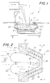
- Fig. 1 is a vertical section view of a galvanizing apparatus according to the present invention.
- Fig. 2 is a vertical section view of a conical projection from the side wall of a galvanizing vessel.
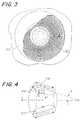
- Fig. 3 is a partial cutaway view of a conical induction furnace in the direction 3-3 indicated in Fig.2.
- Fig. 4 is a schematic diagram of a conical furnace according to the invention.
- Fig. 5 is a vertical section view of a flat inductor heating element disposed on the side wall of a galvanizing pot.
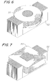
- Fig. 6 is a perspective view of a flat round induction heating coil.
- Fig. 7 is a perspective view of a flat rectangular induction heating coil.
- a galvanizing apparatus 1 according to a first embodiment of the present invention is depicted in Fig. 1.
- a continuous metal strip 2 passes over rollers 3, 4 to be directed into, through, and out of a bath of molten galvanizing metal 5 .
- the molten metal 5 is contained in a vessel (or "pot") 10 .
- Attached to the vessel 10 is at least one conical coreless induction furnace 20.
- the interior space 21 of the conical furnace 20 communicates with the interior of the vessel 10 through an opening 22 in the side wall 12 of the vessel 10 .
- Fig. 2 shows the conical furnace 20 in detail.
- the conical furnace 20 is mounted on the side wall 12 of the vessel with the largest radius R of the conical shape adjacent to the side wall 12 .
- the radius R decreases along the outward projection of the conical furnace 20 from the side wall 12 .
- Both the side wall 12 of the vessel and the interior surface of the conical furnace 20 are lined with a refractory material 30 to protect the vessel 10 and furnace 20 from the extreme heat of the molten metal.
- the furnace 20 has an induction heating coil 24 wound in a plurality of turns outside the refractory material 30 conforming to the conical shape of the furnace.
- a plurality of magnetic shunts 32 overlie the coil turns 24 to confine and direct the magnetic field that the coil 24 produces when energized by alternating frequency current.
- An exterior shell 36 which may be metal, polymeric, ceramic or other material, encloses the conical furnace 20 .
- Energizing the induction coil 24 in the conical furnace with an alternating current creates a strong magnetic field that alternately expands and collapses at the same frequency as the energizing current.
- the magnetic field induces an electric current in the melt 38 .
- the interaction of the electric current and the inherent resistance of the metal comprising the melt generates the heat that keeps the melt 38 liquid.
- a physical force within the melt results from the interaction of the magnetic field and the induced electric current in the melt. This force, known as the Lorentz force, causes stirring currents 40, 42 to flow within the melt 38 .
- the stirring currents move the hottest metal away from the conical furnace 20 and draw cooler metal into the furnace.
- Fig. 3 shows the arrangement of the magnetic shunts over the coil winding in the conical furnace.
- the exterior shell 36 of the furnace is shown in a partial cutaway view, with the narrow end of the conical furnace (at the center of the Figure) closest to the viewer and the widest radius of the cone (where it joins the side wall of the vessel) farther away.
- Each magnetic shunt 32 is a thin ferrous strip having flat faces on two sides and two narrow edges on its top and bottom.
- Each shunt 32 is arranged along the surface of the induction coil with one narrow edge facing outward and the flat faces of the strip facing the neighboring shunts.
- the magnetic shunts 32 confine and direct the magnetic field produced by the coil winding 24 . Though, as illustrated in Fig. 3, there may be small air gaps between them, the shunts 32 are magnetically coupled to each other. Provided that the magnetic field of the shunts 40 is sufficiently strong compared to that created by the induction coil 24 , the induction field that would otherwise extend out from the furnace exterior does not escape the confines of the conical induction furnace. The magnetic field within the furnace also tends to be more concentrated and aligned with the conical surface of the furnace. As illustrated in Fig. 2, the induced electric current in the melt and the magnetic field from the coil interact to produce stirring currents 40, 42 in the melt 38 .
- Fig. 4 illustrates the magnetic field orientation and effect in the conical furnace of the invention.
- the purpose of the conically shaped induction furnace on the side of the galvanizing vessel is to generate a uniform stirring pattern of molten metal within the induction furnace and to project it into the vessel.
- the stirring current is the product of the Lorentz force acting on the melt.
- FIG. 5 A second embodiment of the present invention is shown in Fig. 5.
- the vessel of the galvanizing apparatus has a straight interior surface 16 lined with refractory material 30 .
- Mounted on the outside of the vessel is a flat inductor element 50 .
- the inductor element is comprised of a many turns of electrical conductor wound in a simple shape, such as a circle or rectangle.
- Magnetic shunts 52 enclose the outer surface of the inductor element 50 to confine and direct the induced magnetic field B into the vessel and the melt contained within it.
- the Lorentz forces associated with the induced magnetic field and electric current in the melt produce stirring currents 54 in the melt.
- the stirring currents 54 flow away from the center of the windings of the inductor element 50 , causing part of the melt to flow toward the inductor element to replace the metal flowing away from it.
- inductor element 50 and associated magnetic shunts 52 are enclosed within a shell 56 of suitable material.
- Figs. 6 and 7 illustrate two forms that the wound flat inductor 50 can take, though there may be several equally useful forms.
- Fig. 6 shows a circular wound inductor 50 comprised of many turns of electrical conductor.
- Fig. 7 shows a rectangular inductor 50 . Both of these inductors are enclosed on one side by magnetic shunts 52 .
- the shunts 52 also occupy the void at the center of the windings of each inductor.
- the shunt material in the center forces the field outward toward the melt when the inductor 50 is mounted on the wall of the galvanizing vessel.
Landscapes
- Chemical & Material Sciences (AREA)
- Chemical Kinetics & Catalysis (AREA)
- Engineering & Computer Science (AREA)
- Materials Engineering (AREA)
- Mechanical Engineering (AREA)
- Metallurgy (AREA)
- Organic Chemistry (AREA)
- Coating With Molten Metal (AREA)
- General Induction Heating (AREA)
Claims (11)
- Galvanisierungsvorrichtung (1) zum Erhitzen flüssigen Metalls für Überzüge, die aufweist:einen Behälter (10) zum Aufnehmen geschmolzenen Metalls, wobei der Behälter eine Boden und eine senkrechte Seitenwand (122) mit Innen- und Außenoberflächen und mindestens einem kernlosen Induktionsofen (20), wobei der kernlose Induktionsofen aufweist:mindestens eine konische von dieser Behälter Außenwand nach außen gerichtete Erhebung, wobei diese mindestens eine Erhebung sowohl in den Innen- und Außen Oberflächen der Seitenwind so ausgebildet ist, sodaß sowohl die Innen- und Außenoberflächen der Seitenwand eine Außenerhebung mit konischer Form bilden, wobei diese mindestens eine konische Erhebung einen größten Radius neben der Seitenwand besitzt, wobei der Radius entlang der Außenerstreckung von der Seitenwand abnimmt;und mindestens eine Induktionsheizspule (24) zum Erhitzen und Rühren des geschmolzenen Metalls, die helixartig so auf der konischen Erhebung auf dem Behälteräußeren gewickelt ist, daß die Induktionsheizspule die Form der konischen Erhebung annimmt.
- Galvanisierungsvorrichtung wie in Anspruch 1 beansprucht, wobei die Behälterinnenoberfläche mit Refrakter-Material (30) ausgekleidet ist, wobei das Refrakter-Material der mindestens einen nach außen gerichteten Erhebung von den Seitenwänden entspricht.
- Galvanisierungsvorrichtung wie in Anspruch 1 oder 2 beansprucht, wobei mehrere magnetische Nebenschlüsse (32) um die Induktionsheizspule angeordnet sind.
- Galvanisierungsvorrichtung wie in Anspruch 3 beansprucht, wobei jeder der mehreren magnetischen Nebenschlüsse (32) axial über der Spule (24) vom größten Radius der konischen Erhebung zum kleinsten Radius angeordnet ist.
- Galvanisierungsvorrichtung wie in Anspruch 3 oder 4 beansprucht, wobei die mehreren magnetischen Nebenschlüsse (32) in im wesentlichen kreisförmiger Konfiguration angeordnet sind, wobei die magnetischen Nebenschlüsse einen kollektiven konischen magnetischen Nebenschluß über der Induktionsspule bilden.
- Galvanisierungsvorrichtung wie in Ansprüchen 3, 4 oder 5 beansprucht, wobei eine Schutzschale (36) die Spule (24) und die magnetischen Nebenschlüsse (32) auf dem Äußeren der konischen Erhebung abschirmt.
- Galvanisierungsvorrichtung zum Erhitzen flüssiger Metalls für Überzüge wie in irgendeinem der Ansprüche 1 bis 6 beansprucht, wobei der Behälter zur Aufnahme geschmolzenen Metalls ein kreisförmiger Behälter (10) mit einem Boden und einer runden senkrechten Seitenwand (12) ist.
- Galvanisierungsvorrichtung zum Erhitzen flüssiger Metalls für Überzüge, die aufweist: einen Behälter zur Aufnahme geschmolzenen Metalls, wobei der Behälter einen Boden und vertikale Seitenwände aufweist, wobei die Seitenwände Innen- und Außenoberflächen besitzen; und mindestens eine flache Induktionsspule (50) zur Induktion eines magnetischen Feldes im Behälter, wobei der Inductor gegen die Außenoberfläche einer Seitenwand angeordnet ist.
- Galvanisierungsvorrichtung wie in Anspruch 8 oder 9 beansprucht, wobei die flache Induktionsspule (50) von einem magnetischen Nebenschluß ( 52) umgeben ist, um das Magnetfeld des Induktors zu begrenzen.
- Galvanisierungsvorrichtung wie in Anspruch 8 oder 9 beansprucht, wobei die flache Induktionsspule (50) mehrere Leiterwindungen aufweist, die kreisförmig um eine Zentralöffnung gebildet sind.
- Galvanisierungsvorrichtung wie in Anspruch 8 oder 9 beansprucht, wobei die flache Induktionsspule (50) mehrere Spulenwindungen, die rechtwinkelig um eine Zentralöffnung gebildet sind, aufweist.
Applications Claiming Priority (2)
| Application Number | Priority Date | Filing Date | Title |
|---|---|---|---|
| US551660 | 1995-11-01 | ||
| US08/551,660 US5787110A (en) | 1995-11-01 | 1995-11-01 | Galvanizing apparatus with coreless induction furnace |
Publications (2)
| Publication Number | Publication Date |
|---|---|
| EP0770697A1 EP0770697A1 (de) | 1997-05-02 |
| EP0770697B1 true EP0770697B1 (de) | 1999-03-31 |
Family
ID=24202173
Family Applications (1)
| Application Number | Title | Priority Date | Filing Date |
|---|---|---|---|
| EP96304509A Expired - Lifetime EP0770697B1 (de) | 1995-11-01 | 1996-06-18 | Feuerverzinkungsanlage mit kernlosen Induktionsofen |
Country Status (6)
| Country | Link |
|---|---|
| US (1) | US5787110A (de) |
| EP (1) | EP0770697B1 (de) |
| JP (1) | JP3085652B2 (de) |
| KR (1) | KR100243642B1 (de) |
| AU (1) | AU683798B2 (de) |
| DE (1) | DE69601914T2 (de) |
Families Citing this family (4)
| Publication number | Priority date | Publication date | Assignee | Title |
|---|---|---|---|---|
| FR2807070B1 (fr) * | 2000-03-28 | 2002-05-17 | Delot Process Sa | Procede et dispositif pour realiser un revetement metallique sur un objet sortant d'un bain de metal fondu |
| DE10253464A1 (de) * | 2002-11-16 | 2004-05-27 | INDUGA Industrieöfen und Giesserei-Anlagen GmbH & Co. KG | Vorrichtung und Verfahren zur Warmtauchbeschichtung von band- oder drahtförmigem Material |
| US8543178B2 (en) * | 2007-11-02 | 2013-09-24 | Ajax Tocco Magnethermic Corporation | Superconductor induction coil |
| EP2446702B1 (de) | 2009-06-21 | 2016-01-27 | Inductotherm Corp. | Elektrische induktionsheizung und rühren eines elektrisch leitfähigen materials in einem eindämmungsgefäss |
Family Cites Families (11)
| Publication number | Priority date | Publication date | Assignee | Title |
|---|---|---|---|---|
| GB662524A (en) * | 1948-12-27 | 1951-12-05 | Birlec Ltd | Improvements in, or relating to, a method of and apparatus for galvanizing and like metal coating |
| US2647304A (en) * | 1951-08-18 | 1953-08-04 | Wheeling Steel Corp | Process of terne coating metal and terne coated product |
| AT277598B (de) * | 1966-02-22 | 1969-12-29 | Wiener Schwachstromwerke Gmbh | Trommelofen mit auswechselbaren Tiegelinduktoren |
| US3602625A (en) * | 1970-04-06 | 1971-08-31 | Ajax Magnethermic Corp | Horizontal coreless induction furnace |
| SU685712A1 (ru) * | 1977-06-17 | 1979-09-18 | Предприятие П/Я А-7186 | Устройство дл нанесени покрытий на многожильные провода |
| JPS59123753A (ja) * | 1982-12-28 | 1984-07-17 | Sumitomo Metal Ind Ltd | 連続溶融メツキ法およびその装置 |
| DE3428999C2 (de) * | 1984-08-07 | 1986-08-14 | Otto Junker Gmbh, 5107 Simmerath | Heißtauchmetallisierungsvorrichtung und Heißtauchmetallisierungsverfahren |
| JPH03110059A (ja) * | 1989-09-22 | 1991-05-10 | Kawasaki Steel Corp | 溶融金属の不純物除去方法とその装置 |
| JP2722794B2 (ja) * | 1990-08-01 | 1998-03-09 | 富士電機株式会社 | 低融点金属対策を施したるつぼ形誘導炉 |
| US5354970A (en) * | 1992-06-30 | 1994-10-11 | Inductotherm Corp | Pot for batch coating of continuous metallic strip |
| SE470435B (sv) * | 1992-08-07 | 1994-03-07 | Asea Brown Boveri | Sätt och anordning att omröra en metallsmälta |
-
1995
- 1995-11-01 US US08/551,660 patent/US5787110A/en not_active Expired - Lifetime
-
1996
- 1996-06-18 DE DE69601914T patent/DE69601914T2/de not_active Expired - Fee Related
- 1996-06-18 EP EP96304509A patent/EP0770697B1/de not_active Expired - Lifetime
- 1996-06-27 AU AU56217/96A patent/AU683798B2/en not_active Ceased
- 1996-10-25 JP JP08299885A patent/JP3085652B2/ja not_active Expired - Fee Related
- 1996-11-01 KR KR1019960051959A patent/KR100243642B1/ko not_active Expired - Fee Related
Also Published As
| Publication number | Publication date |
|---|---|
| AU5621796A (en) | 1997-06-05 |
| AU683798B2 (en) | 1997-11-20 |
| KR100243642B1 (ko) | 2000-03-02 |
| US5787110A (en) | 1998-07-28 |
| DE69601914D1 (de) | 1999-05-06 |
| JPH09125217A (ja) | 1997-05-13 |
| EP0770697A1 (de) | 1997-05-02 |
| KR970027353A (ko) | 1997-06-24 |
| JP3085652B2 (ja) | 2000-09-11 |
| DE69601914T2 (de) | 1999-12-09 |
Similar Documents
| Publication | Publication Date | Title |
|---|---|---|
| EP0653967B1 (de) | Verfahren und vorrichtung zum rühren einer schmelze | |
| KR100290447B1 (ko) | 스트립재료 표면의 코팅 방법 및 장치 | |
| US5787110A (en) | Galvanizing apparatus with coreless induction furnace | |
| KR100264946B1 (ko) | 전자기식장치를갖는연속주조몰드 | |
| EP2167697B1 (de) | Verfahren und vorrichtung zur steuerung der dicke einer beschichtung auf einem flachen metallprodukt | |
| AU664662B2 (en) | Induction heated meniscus coating vessel | |
| CA2210005C (en) | Method and apparatus for holding molten metal | |
| US5662969A (en) | Hot coating by induction levitation | |
| CA2217329C (en) | Furnace plant | |
| KR20110025231A (ko) | 연속 용융 도금에 의해 평평한 금속 제품을 코팅하는 전자기 장치 및 이 장치의 코팅 프로세스 | |
| KR20010040915A (ko) | 미세 금속 입자 및/또는 금속 함유 입자를 용융시키기위한 방법 및 유도 전기로 | |
| EP0577273B1 (de) | Behälter zur Tauchbeschichtung eines fortlaufenden metallischen Bandes | |
| JPS60213352A (ja) | 液体金属の電磁撹拌ポンプ | |
| RU97119726A (ru) | Печная установка | |
| EP0132280B1 (de) | Verfahren zum erhitzen geschmolzenen stahls im trichter einer kontinuierlichen giessvorrichtung | |
| US4953487A (en) | Electromagnetic solder tinning system | |
| US4276082A (en) | Process for the heating and/or melting of metals and an induction furnace to carry out the process | |
| JPH0494090A (ja) | 誘導電気炉内の磁界制御方法 | |
| CA2320561C (en) | Controllable variable magnetic field apparatus for flow control of molten steel in a casting mold | |
| US6341642B1 (en) | Controllable variable magnetic field apparatus for flow control of molten steel in a casting mold | |
| AU685907B2 (en) | Hot coating by induction levitation | |
| RU2109594C1 (ru) | Устройство и способ для магнитного удержания расплавленного металла | |
| SU1117864A1 (ru) | Погружной индукционный нагреватель дл нагрева металлического расплава | |
| JPH03199887A (ja) | 電子ビーム溶解炉 | |
| SU889324A1 (ru) | Устройство дл пайки волной расплавленного припо |
Legal Events
| Date | Code | Title | Description |
|---|---|---|---|
| PUAI | Public reference made under article 153(3) epc to a published international application that has entered the european phase |
Free format text: ORIGINAL CODE: 0009012 |
|
| 17P | Request for examination filed |
Effective date: 19960702 |
|
| AK | Designated contracting states |
Kind code of ref document: A1 Designated state(s): BE DE FR GB IT NL |
|
| GRAG | Despatch of communication of intention to grant |
Free format text: ORIGINAL CODE: EPIDOS AGRA |
|
| 17Q | First examination report despatched |
Effective date: 19980610 |
|
| GRAG | Despatch of communication of intention to grant |
Free format text: ORIGINAL CODE: EPIDOS AGRA |
|
| GRAH | Despatch of communication of intention to grant a patent |
Free format text: ORIGINAL CODE: EPIDOS IGRA |
|
| GRAH | Despatch of communication of intention to grant a patent |
Free format text: ORIGINAL CODE: EPIDOS IGRA |
|
| GRAA | (expected) grant |
Free format text: ORIGINAL CODE: 0009210 |
|
| AK | Designated contracting states |
Kind code of ref document: B1 Designated state(s): BE DE FR GB IT NL |
|
| ET | Fr: translation filed | ||
| REF | Corresponds to: |
Ref document number: 69601914 Country of ref document: DE Date of ref document: 19990506 |
|
| PLBE | No opposition filed within time limit |
Free format text: ORIGINAL CODE: 0009261 |
|
| STAA | Information on the status of an ep patent application or granted ep patent |
Free format text: STATUS: NO OPPOSITION FILED WITHIN TIME LIMIT |
|
| 26N | No opposition filed | ||
| REG | Reference to a national code |
Ref country code: GB Ref legal event code: IF02 |
|
| PGFP | Annual fee paid to national office [announced via postgrant information from national office to epo] |
Ref country code: GB Payment date: 20040505 Year of fee payment: 9 |
|
| PGFP | Annual fee paid to national office [announced via postgrant information from national office to epo] |
Ref country code: NL Payment date: 20040510 Year of fee payment: 9 |
|
| PGFP | Annual fee paid to national office [announced via postgrant information from national office to epo] |
Ref country code: FR Payment date: 20040602 Year of fee payment: 9 |
|
| PGFP | Annual fee paid to national office [announced via postgrant information from national office to epo] |
Ref country code: DE Payment date: 20040630 Year of fee payment: 9 |
|
| PG25 | Lapsed in a contracting state [announced via postgrant information from national office to epo] |
Ref country code: IT Free format text: LAPSE BECAUSE OF NON-PAYMENT OF DUE FEES Effective date: 20050618 Ref country code: GB Free format text: LAPSE BECAUSE OF NON-PAYMENT OF DUE FEES Effective date: 20050618 |
|
| PG25 | Lapsed in a contracting state [announced via postgrant information from national office to epo] |
Ref country code: NL Free format text: LAPSE BECAUSE OF NON-PAYMENT OF DUE FEES Effective date: 20060101 |
|
| PG25 | Lapsed in a contracting state [announced via postgrant information from national office to epo] |
Ref country code: DE Free format text: LAPSE BECAUSE OF NON-PAYMENT OF DUE FEES Effective date: 20060103 |
|
| PG25 | Lapsed in a contracting state [announced via postgrant information from national office to epo] |
Ref country code: FR Free format text: LAPSE BECAUSE OF NON-PAYMENT OF DUE FEES Effective date: 20060228 |
|
| GBPC | Gb: european patent ceased through non-payment of renewal fee |
Effective date: 20050618 |
|
| NLV4 | Nl: lapsed or anulled due to non-payment of the annual fee |
Effective date: 20060101 |
|
| REG | Reference to a national code |
Ref country code: FR Ref legal event code: ST Effective date: 20060228 |
|
| PGFP | Annual fee paid to national office [announced via postgrant information from national office to epo] |
Ref country code: BE Payment date: 20090619 Year of fee payment: 14 |
|
| BERE | Be: lapsed |
Owner name: *INDUCTOTHERM CORP. Effective date: 20100630 |
|
| PG25 | Lapsed in a contracting state [announced via postgrant information from national office to epo] |
Ref country code: BE Free format text: LAPSE BECAUSE OF NON-PAYMENT OF DUE FEES Effective date: 20100630 |