EP0770541A2 - Car body carrier - Google Patents
Car body carrier Download PDFInfo
- Publication number
- EP0770541A2 EP0770541A2 EP96111439A EP96111439A EP0770541A2 EP 0770541 A2 EP0770541 A2 EP 0770541A2 EP 96111439 A EP96111439 A EP 96111439A EP 96111439 A EP96111439 A EP 96111439A EP 0770541 A2 EP0770541 A2 EP 0770541A2
- Authority
- EP
- European Patent Office
- Prior art keywords
- members
- hold
- wheels
- front wheel
- wheel
- Prior art date
- Legal status (The legal status is an assumption and is not a legal conclusion. Google has not performed a legal analysis and makes no representation as to the accuracy of the status listed.)
- Granted
Links
Images


Classifications
-
- B—PERFORMING OPERATIONS; TRANSPORTING
- B60—VEHICLES IN GENERAL
- B60S—SERVICING, CLEANING, REPAIRING, SUPPORTING, LIFTING, OR MANOEUVRING OF VEHICLES, NOT OTHERWISE PROVIDED FOR
- B60S13/00—Vehicle-manoeuvring devices separate from the vehicle
-
- B—PERFORMING OPERATIONS; TRANSPORTING
- B61—RAILWAYS
- B61B—RAILWAY SYSTEMS; EQUIPMENT THEREFOR NOT OTHERWISE PROVIDED FOR
- B61B10/00—Power and free systems
- B61B10/04—Power and free systems with vehicles rolling trackless on the ground
- B61B10/046—Impellers
-
- B—PERFORMING OPERATIONS; TRANSPORTING
- B62—LAND VEHICLES FOR TRAVELLING OTHERWISE THAN ON RAILS
- B62D—MOTOR VEHICLES; TRAILERS
- B62D65/00—Designing, manufacturing, e.g. assembling, facilitating disassembly, or structurally modifying motor vehicles or trailers, not otherwise provided for
- B62D65/02—Joining sub-units or components to, or positioning sub-units or components with respect to, body shell or other sub-units or components
- B62D65/18—Transportation, conveyor or haulage systems specially adapted for motor vehicle or trailer assembly lines
Definitions
- the present invention relates to apparatus for carrying car bodies between lines of conveyance, inspection, storage, etc. and equipments for finished automobiles in an automobile plant as an example.
- the conventional methods for carrying automobiles or other car bodies having wheels between conveyors laid in series to form a conveyance line as an example, or between a conveyor and a lifter include:
- the above method 1 needs a driver to always be in a place where car bodies are carried, so that the expense is high.
- the method 2 needs large motive power and a large apparatus for transferring a car body onto a pallet.
- the wheel positions, lifting positions, etc. depend on the types of car bodies, so that the mechanism and control of the transfer means is complex.
- the method 3 needs to change the point of engagement of a traction means for different types of car bodies, and therefore needs a complex apparatus as a whole.
- the direction of the wheels for steering of a car body being pulled is not fixed to the direction of carriage, so that it is difficult to carry the body precisely and smoothly along a carriage line.
- a car body carrier is an apparatus for carrying a car body having front and rear pairs of right and left wheels, which can idle, by moving the body along a carriage path with the wheels rotating on a floor.
- the carrier includes a front wheel direction regulation means, a front wheel hold means, and a drive means for moving these means together along the path.
- the front wheel direction regulation means has a pair of right and left deflection prevention members for contact with sides of the front wheels, respectively, in such a manner that these wheels can rotate, in order to regulate the direction of these wheels to the direction of carriage.
- the front wheel hold means has a pair of rear hold members for contact with the peripheral surfaces of the front wheels, respectively, behind these wheels to push these wheels forward in such a manner that these wheels can rotate.
- the front wheel hold means also has a pair of front hold members positioned in front of the front wheels, respectively, to prevent these wheels from moving forward away from the rear hold members.
- a car body is conveyed to the start end of a carriage path by a conveyance means.
- the deflection prevention members of the front wheel direction regulation means are put into contact with either the inner or the outer surfaces of the front wheels of the car body to regulate the direction of these wheels in the direction of carriage.
- the rear hold members of the front wheel hold means are positioned behind the front wheels, while the front hold members are positioned in front of these wheels.
- the drive means moves the deflection prevention members and the hold members together along the path. This makes the rear hold members push the front wheels forward to propel the car body along the path.
- the front hold members in front of the front wheels prevent the car body from being moved forward faster than the rear hold members by inertia.
- the deflection prevention members in contact with the front wheels prevent the direction of these wheels from deflecting or inclining from the direction of carriage. As a result, the car body is carried along the path securely and smoothly at a specified speed. Because the front wheels are allowed to rotate by the various members in contact with them, the car body can travel smoothly with the wheels rotating.
- the car body carrier carries a car body M with wheels by pushing the front wheels FW, which are idle wheels for steering, between the conveyors constituting the car carriage lines in facilities such as those for manufacturing, inspecting, lifting, elevating and storing cars, or on the carriage lines between the facilities.
- the carrier is explained as carrying a car body M, as stated above, on the carriage path L provided from ends of a pair of parallel conveyors for carrying a car body with the wheels supported on them to the specified position from which a car goes out.
- the car body carrier includes a traveler 3, which can travel along the carriage path L.
- the traveler 3 is supported movably on a pair of guide rails 2R and 2L in the form of vertical flat plates, which are laid oppositely on both sides of a square or rectangular groove 1 in a floor.
- the groove 1 is formed along the carriage line L from the space between a pair of right and left parallel conveyors RC and LC, which constitute a conveyor line, to the space between a pair of right and left carriage floors F, which are floor divisions.
- Installed at the outlet of the conveyor line (conveyors RC and LC) are a pair of right and left floating tables 9, which are used to center the car body M.
- the traveler 3 includes a front wheel direction or orientation regulation means 5 having deflection prevention members 4R and 4L, which are rollers for contact with the inner sides of the right and left front wheels FW of the car body M.
- the traveler 3 also includes a front wheel hold means 8, which has a pair of front hold members 6R and 6L and a pair of rear hold members 7R and 7L.
- the front members 6R and 6L are long rollers positioned in front of the front wheels FW to restrict the front wheels from moving forward.
- the rear members 7R and 7L are long rollers positioned in the rear of the front wheels FW to push the front wheels forward.
- the traveler 3 is a drive means for moving the front wheel direction regulator 5 and holder 8 together along the carriage path L. As shown in Figs. 2 - 4, the traveler 3 includes a carriage 3a and a drive 3b.
- the carriage 3a has front and rear support rollers 11, which roll on the upper surfaces of the guide rails 2R and 2L.
- the carriage 3a also has front and rear flotation or relief preventing rollers 12, which contact with the lower surfaces of the rails.
- the carriage 3a further has travel direction regulating rollers 13 provided near its front end, which contact with the right and left surfaces of the right rail 2R.
- the drive 3b has a drive roller 14 of large diameter, which contacts with the inner side of the right guide rail 2R.
- the drive 3b also has backup rollers 15 in rows in parallel with the rail 2R.
- the rollers 15 contact with the outer side of the rail 2R opposite to the drive roller 14.
- the drive 3b further has a frame 16. Fixed to the frame 16 are a pair of front and rear slide guide rods 17, which extend horizontally at right angles with the rails 2R and 2L.
- the rods 17 support a movable frame 18, which can slide along it and carries a drive unit 19.
- the drive unit 19 has a vertical output shaft, which is fixed to the drive roller 14.
- Fixed to each slide guide rod 17 is a spring shoe 17b.
- Each rod 17 supports a compression coil spring 17a around it between the shoe 17b and movable frame 18.
- the springs 17a around the rods 17 urge the movable frame 18 toward the right rail 2R, so that the drive roller 14 engages or contacts compressively with the inner side of the rail 2R.
- the backup rollers 15 are mounted on the drive frame 16 through brackets 16a.
- the drive unit 19 includes a drive motor 18a for rotating the drive roller 14.
- the motor 18a, its control and other electrical equipment or apparatus on the traveler 3 are fed or energized through a cable (not shown).
- the equipment or apparatus may be fed from a feeding rail through a non-contact current collector or another current collector.
- the front wheel direction regulation means 5 carries the front and rear deflection prevention members 4R and 4L in right and left pairs.
- the regulation means 5 includes a linear guide 20 and a pair of right and left, laterally movable frames 21R and 21L, which are guided by the guide 20, and which can move horizontally and perpendicularly to the guide rails 2R and 2L.
- the regulation means 5 also includes a frame mover 22 for synchronously protruding and retracting the frames 21R and 21L.
- the regulation means 5 further includes a cylinder 23 for driving the mover 22 to move the frames 21R and 21L.
- the frame mover 22 includes a rack and pinion mechanism.
- the carriage 3a includes a support frame 24, on which a vertical rotating shaft 25 is supported rotatably. Fixed to the shaft 25 are an input pinion 25a and an output pinion 25b.
- the piston rod of the cylinder 23 is connected to a rack shaft 26, which is supported on the support frame 24 slidably in parallel to the guide rails 2R and 2L.
- the teeth of the rack shaft 26 engage with the input pinion 25a.
- Connected to the laterally movable frames 21R and 21L are a pair of right and left output rack shafts 27R and 27L, respectively.
- the support frame 24 supports the rack shafts 27R and 27L, which can slide on it horizontally and perpendicularly to the rails 2R and 2L.
- the rack shafts 27R and 27L have mutually facing teeth, which engage with the output pinion 25b.
- the limits of sliding movement of the input rack shaft 26 are detected by limit switches 28.
- the laterally movable frames 21R and 21L each support a pair of front and rear, horizontal support rods 29, which can slide laterally thereon.
- the outer end of each rod 29 has a bracket 30, on which one of the deflection prevention rollers 4R and 4L is supported rotatably.
- Each rod 29 is urged laterally outward by a compression coil spring 31, which is interposed between the associated frame 21R or 21L and bracket 30.
- the rack-and-pinion frame mover 22 reciprocates the laterally movable frames 21R and 21L with the deflection prevention rollers 4R and 4L synchronously in lateral symmetry. Therefore, if the front wheels FW are dislocated laterally from their centering positions, the frames 21R and 21L stop with only one pair of rollers 4R and 4L contacting with the adjacent wheel FW. This condition can be judged or determined from the states of the limit switches 32 for the respective rollers 4R and 4L. It is therefore possible to judge from the states of the switches 32 whether the wheels FW are centered or not.
- the deflection prevention members 4R and 4L are taper rollers, which are smaller upward in diameter so that they contact with the inner surfaces of the tires on the front wheels FW, not directly with the metal wheels.
- the taper rollers are so inclined that their axes extend near the axis WS of the wheels FW.
- the height or level of the wheel axis WS varies with the tire diameter of the wheels FW, which depends on the type of the car body M. Therefore, the inclination of the taper rollers is set as stated above by assuming the position of the axis WS of a front wheel of an average tire diameter.
- the carriage path L is linear along the conveyors RC and LC. Therefore, the pairs of front and rear deflection prevention members 4R and 4L are arranged in parallel with the path L.
- the pair of front wheels FW are regulated to be parallel with the path L by the members 4R and 4L contacting with their inner surfaces, so that the car body M moves straight along the path L. If the path L curved horizontally, the front members 4R and 4L might be dislocated laterally from the rear members, so that the wheels FW might be inclined forcedly in the direction in which the path L curves.
- Actuators might be provided to move the front and rear pairs of members 4R and 4L independently from each other. The independent lateral movements of the members 4R and 4L could, midway on the path L, change the direction of the wheels FW regulated by these members, to change the direction of movement of the car body M.
- the front wheel hold means 8 includes the front hold members 6R and 6L, which are long rollers, and the rear hold members 7R and 7L, which are long rollers positioned behind the front wheel FW so as to push the wheels forward.
- the hold members 6R, 6L, 7R and 7L can be pivoted horizontally by an angle of 90 degrees on their respective vertical pins 41R, 41L, 42R and 42L by front and rear pivoting devices 43 and 44. Consequently, each of these members can be switched between a waiting or standby position X, which is shown by two-dot chain lines, in parallel with the carriage path L and an operating position Y, which is shown by solid lines, at a right angle with the path L.
- the carriage 3a of the traveler 3 includes a linear guide 51 in parallel with the carriage path L.
- the front pivoting device 43 includes a movable frame 52 supported longitudinally movably through a slider on a front portion of the guide 51.
- the device 43 also includes a cylinder 53 for reciprocating the frame 52 longitudinally.
- the front hold rollers 6R and 6L are supported in the form of cantilevers by the roller bearings 56R and 56L at the outer ends of L-shaped arms 54R and 54L, respectively.
- the arms 54R and 54L can pivot or turn on the vertical pins 41R and 41L, respectively.
- the outer ends of the front portions 54a of the arms 54R and 54L are connected to the frame 52 through links 55R and 55L, respectively.
- the rear pivoting device 44 includes a movable frame 62, which is supported longitudinally movably through a slider on a rear portion of the linear guide 51.
- the device 44 also includes a cylinder 63 for longitudinally reciprocating the frame 62.
- the rear hold rollers 7R and 7L are supported in the form of cantilevers by roller bearings 67R and 67L, respectively.
- the bearings 67R and 67L are supported pivotably in vertical planes by the longitudinal pins 66 on the outer ends of L-shaped arms 64R and 64L, respectively.
- the arms 64R and 64L can pivot on the vertical pins 42R and 42L, respectively.
- the outer ends of the rear portions 64a of the arms 64R and 64L are connected to the frame 62 through links 65R and 65L, respectively. Therefore, the rollers 7R and 7L can pivot upward on the horizontal pins 66 to avoid obstacles on the carriage floors F.
- the front and rear pivoting devices 43 and 44 are so constructed that, when the front and rear hold members 6R, 6L, 7R and 7L are in their respective operating positions Y, the front and rear portions 54a and 64a of the L-shaped arms 54R, 54L, 64R and 64L are parallel with the directions in which the movable frames 52 and 62 move, and the links 55R, 55L, 65R and 65L are perpendicular to these directions. Accordingly, the moments which the members 6R, 6L, 7R and 7L receive from the front wheels FW are born by the compressive stresses of the respective links 55R, 55L, 65R and 65L, so that any force which moves the frames 52 and 62 is not generated.
- the rear hold members 7R and 7L are taper rollers, which are larger in diameter toward their free ends. Consequently, when the rollers 7R and 7L contact with the front wheels FW and push them forward, the directions of the pushing forces are inclined a little toward the center of the car body M.
- the free ends larger in diameter of the rollers 7R and 7L support receiving rollers 68R and 68L, respectively, which are even larger in diameter and rotatable on them.
- the pair of right and left floating tables 9 shown in Fig. 1 are of the same structure. As shown in Figs. 11 and 12, the tables 9 are placed in a pair of right and left pits 71, respectively, which are each formed in one of the carriage floors F. Each table 9 includes a table body 73, which is supported laterally movably through sliders 72a on a pair of right and left linear guides 72 in one of the pits 71. The table body 73 is flush with the associated floor F. Between the guides 72 extends a lateral guide shaft 74 in parallel with them, on which a pair of right and left spring shoes 76a and 76b are supported slidably.
- the shaft 74 also supports a compression coil spring 75 between the shoes 76a and 76b, which are urged on stoppers 77a and 77b, respectively, by the spring 75.
- the table body 73 has a pair of right and left brackets 78a and 78b projecting from its lower surface. The brackets 78a and 78b contact with the outer surfaces of the shoes 76a and 76b, respectively, as stopped by the respective stoppers 77a and 77b as stated above.
- the cylinder 23 of the front wheel direction regulation means 5 is actuated again.
- the detection signals from the limit switches 32 that the wheels FW of a car body M at the downstream end positions of the conveyors RC and LC are not centered, when the deflection prevention members 4R and 4L of the means 5 are operated on the wheels FW, it might be possible to keep the cylinder 23 operating, with the centering force acted on the wheels FW, while the car body M is carried until the wheels FW have moved onto the tables 9.
- a car body M is conveyed at a specified speed with their right and left wheels on the conveyors RC and LC, respectively.
- the car body M being conveyed is fitted with a hand brake, a gear shifter, etc., which are free or neutral so that all of the wheels can idle.
- the wheels for steering which may be the front wheels FW, are directed nearly forward or straight, but are not fixed and may therefore be somewhat inclined.
- a detector (not shown) detects the arrival of the car body M at specified positions near the downstream ends of the conveyors RC and LC. This starts the traveler 3, which has waited at the start end position on the carriage path L. The start end position is upstream from the downstream ends of the conveyors RC and LC.
- the started traveler 3 travels forward in synchronism with the car body M on the conveyors RC and LC. Alternatively, the conveyors RC and LC are stopped.
- the cylinder 23 of the front wheel direction regulation means 5 is actuated to make the frame mover 22 move the laterally movable frames 21R and 21L outward.
- the front and rear pivoting devices 43 and 44 of the front wheel hold means 8 are driven to turn the front and rear hold members 6R, 6L, 7R and 7L by the angle of 90 degrees from the waiting positions X to the operating positions Y. This makes the front and rear hold members extend respectively in front of and behind the wheels FW. If the conveyors RC and LC are stopped, the traveler 3 is started to travel forward at this stage.
- the traveler 3 travels in synchronism with the conveyors RC and LC, the rear hold members 7R and 7L start to contact with rear portions of the front wheels FW and push the wheels FW forward, when the car body M has left the downstream ends of the conveyors. If the conveyors RC and LC stop and only the traveler 3 travels, the travel makes these members 7R and 7L push the wheels FW forward.
- the rear hold members 7R and 7L push the circular or circumferential tire surfaces below the axes of the front wheels FW, so that downward reaction is applied to these members.
- the receiving rollers 68R and 68L on the free ends of these members 7R and 7L contact with the carriage floors F, so that the downward reaction is born by the floors.
- the members 7R and 7L are kept substantially horizontal. Therefore, the members 7R and 7L cannot be positioned under the wheels FW, but can securely push them to move the car body M forward. In addition, no excessive force acts on the roots of the members 7R and 7L.
- the rear hold members 7R and 7L are taper rollers, which are larger in diameter toward their free ends. Therefore, the directions of the pushing forces on the front wheels FW can be inclined a little toward the center of the car body M and out of parallel with the direction of carriage. This enables the car body M to travel stably.
- the members 7R and 7L can swing upward on the pins 66, which are parallel with the direction of carriage, so as to easily avoid any obstacles on the carriage floors F.
- the cylinder 23 causes the deflection prevention members 4R or 4L to apply centering force to the front wheel FW dislocated inward, as already explained, when the front wheels FW have transferred from the conveyors RC and RL to the table bodies 73 of the floating tables 9. This moves the front of the car body M laterally together with the table bodies 73 to center the front. Then, the wheels FW are pushed to move from the table bodies 73 onto the carriage floors F, so that the rear of the car body M follows and moves laterally. As a result, the car body M as a whole is centered.
- the traveler 3 is stopped. Then, the cylinder 23 of the front wheel direction regulation means 5 is actuated to retract the laterally movable frames 21R and 21L with the deflection prevention members 4R and 4L away from the front wheels FW. In addition, the front and rear pivoting devices 43 and 44 of the front wheel hold means 8 are actuated to switch the front and rear hold members 6R, 6L, 7R and 7L from the operating positions Y to the waiting positions X by turning these members by the horizontal angle of 90 degrees. Thereafter, the traveler 3 is moved backward to return to the start end position of the path L.
Landscapes
- Engineering & Computer Science (AREA)
- Mechanical Engineering (AREA)
- Transportation (AREA)
- Manufacturing & Machinery (AREA)
- Chemical & Material Sciences (AREA)
- Combustion & Propulsion (AREA)
- Automobile Manufacture Line, Endless Track Vehicle, Trailer (AREA)
Abstract
Description
- The present invention relates to apparatus for carrying car bodies between lines of conveyance, inspection, storage, etc. and equipments for finished automobiles in an automobile plant as an example.
- The conventional methods for carrying automobiles or other car bodies having wheels between conveyors laid in series to form a conveyance line as an example, or between a conveyor and a lifter include:
- 1. a method of driving a car body by an operator or a driver in it;
- 2. a method of transferring a car body onto a pallet and carrying the body on the pallet, as disclosed in Japanese Utility Model First (before exam) Publication S.55-167,921 and Japanese Patent First Publication S.60-19,611 as examples; and
- 3. a method of traction a car body with a traction means engaged with it.
- The above method 1 needs a driver to always be in a place where car bodies are carried, so that the expense is high.
- The method 2 needs large motive power and a large apparatus for transferring a car body onto a pallet. In addition, the wheel positions, lifting positions, etc. depend on the types of car bodies, so that the mechanism and control of the transfer means is complex.
- The
method 3 needs to change the point of engagement of a traction means for different types of car bodies, and therefore needs a complex apparatus as a whole. In addition, the direction of the wheels for steering of a car body being pulled is not fixed to the direction of carriage, so that it is difficult to carry the body precisely and smoothly along a carriage line. - It is therefore the object of the present invention to provide an apparatus for carrying a car body precisely and smoothly without needing a driver and large motive power.
- A car body carrier according to the invention is an apparatus for carrying a car body having front and rear pairs of right and left wheels, which can idle, by moving the body along a carriage path with the wheels rotating on a floor. The carrier includes a front wheel direction regulation means, a front wheel hold means, and a drive means for moving these means together along the path. The front wheel direction regulation means has a pair of right and left deflection prevention members for contact with sides of the front wheels, respectively, in such a manner that these wheels can rotate, in order to regulate the direction of these wheels to the direction of carriage. The front wheel hold means has a pair of rear hold members for contact with the peripheral surfaces of the front wheels, respectively, behind these wheels to push these wheels forward in such a manner that these wheels can rotate. The front wheel hold means also has a pair of front hold members positioned in front of the front wheels, respectively, to prevent these wheels from moving forward away from the rear hold members.
- A car body is conveyed to the start end of a carriage path by a conveyance means. The deflection prevention members of the front wheel direction regulation means are put into contact with either the inner or the outer surfaces of the front wheels of the car body to regulate the direction of these wheels in the direction of carriage. The rear hold members of the front wheel hold means are positioned behind the front wheels, while the front hold members are positioned in front of these wheels. Then, the drive means moves the deflection prevention members and the hold members together along the path. This makes the rear hold members push the front wheels forward to propel the car body along the path. The front hold members in front of the front wheels prevent the car body from being moved forward faster than the rear hold members by inertia. The deflection prevention members in contact with the front wheels prevent the direction of these wheels from deflecting or inclining from the direction of carriage. As a result, the car body is carried along the path securely and smoothly at a specified speed. Because the front wheels are allowed to rotate by the various members in contact with them, the car body can travel smoothly with the wheels rotating.
- Therefore, there is no need of a driver for driving a car body. Of course, there is no need of large motive power and an apparatus for transferring a very heavy car body onto a pallet for carriage. Because a car body is merely pushed forward with its wheels rotating on the carriage floor, even a large car body which is very heavy can be carried securely and smoothly with relatively small thrust. Although the diameters of the front wheels and the distances between the wheels may vary with the car types, the variation can be coped with easily by the deflection prevention members of the front wheel direction regulation means and the hold members of the front wheel hold means. It is therefore easy to securely put the desired carrying operation into practice regardless of the types of car bodies.
- Other features and advantages of the present invention will be understood easily from a preferred embodiment of the invention, which is described below in detail with reference to the accompanying drawings, in which:
- Fig. 1 is a schematic perspective view of a carrier according to the invention;
- Fig. 2 is a plan view of the carrier;
- Fig. 3 is a side view of the carrier;
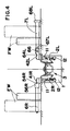
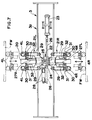
- Fig. 4 is a front view partially in lateral cross section of the carrier, showing the right-hand front hold member and left-hand rear hold member of its front wheel hold means;
- Fig. 5 is a partial plan view of the carrier, showing the drive of its traveler;
- Fig. 6 is a partial side view of the carrier, showing the traveler drive;
- Fig. 7 is a partial plan view of the carrier, showing its front wheel direction regulation means;
- Fig. 8 is a partial side view in longitudinal cross section of the carrier, showing the frame mover of the front wheel direction regulation means;
- Fig. 9 is a partial plan view of the carrier, showing the front wheel hold means;
- Fig. 10 is a partial side view of the carrier, showing the front wheel hold means;
- Fig. 11 is a partial plan view partially cut away of the carrier, showing one of its floating tables;
- Fig. 12 is a partial side view of the carrier, showing the floating table.
- With reference to the drawings, the car body carrier according to the embodiment of the present invention carries a car body M with wheels by pushing the front wheels FW, which are idle wheels for steering, between the conveyors constituting the car carriage lines in facilities such as those for manufacturing, inspecting, lifting, elevating and storing cars, or on the carriage lines between the facilities. In this embodiment, the carrier is explained as carrying a car body M, as stated above, on the carriage path L provided from ends of a pair of parallel conveyors for carrying a car body with the wheels supported on them to the specified position from which a car goes out.
- As shown in Figs. 1 - 4, the car body carrier includes a
traveler 3, which can travel along the carriage path L. Thetraveler 3 is supported movably on a pair ofguide rails traveler 3 includes a front wheel direction or orientation regulation means 5 havingdeflection prevention members - The
traveler 3 also includes a front wheel hold means 8, which has a pair of front holdmembers rear hold members front members rear members - The
traveler 3 is a drive means for moving the frontwheel direction regulator 5 and holder 8 together along the carriage path L. As shown in Figs. 2 - 4, thetraveler 3 includes acarriage 3a and adrive 3b. - The
carriage 3a has front andrear support rollers 11, which roll on the upper surfaces of theguide rails carriage 3a also has front and rear flotation orrelief preventing rollers 12, which contact with the lower surfaces of the rails. Thecarriage 3a further has traveldirection regulating rollers 13 provided near its front end, which contact with the right and left surfaces of theright rail 2R. - As shown in Figs. 5 and 6, the
drive 3b has adrive roller 14 of large diameter, which contacts with the inner side of theright guide rail 2R. Thedrive 3b also hasbackup rollers 15 in rows in parallel with therail 2R. Therollers 15 contact with the outer side of therail 2R opposite to thedrive roller 14. Thedrive 3b further has aframe 16. Fixed to theframe 16 are a pair of front and rearslide guide rods 17, which extend horizontally at right angles with therails rods 17 support amovable frame 18, which can slide along it and carries adrive unit 19. Thedrive unit 19 has a vertical output shaft, which is fixed to thedrive roller 14. Fixed to eachslide guide rod 17 is aspring shoe 17b. Eachrod 17 supports a compression coil spring 17a around it between theshoe 17b andmovable frame 18. The springs 17a around therods 17 urge themovable frame 18 toward theright rail 2R, so that thedrive roller 14 engages or contacts compressively with the inner side of therail 2R. Thebackup rollers 15 are mounted on thedrive frame 16 through brackets 16a. - The
drive unit 19 includes a drive motor 18a for rotating thedrive roller 14. The motor 18a, its control and other electrical equipment or apparatus on thetraveler 3 are fed or energized through a cable (not shown). In such a case that the carriage path L is long, the equipment or apparatus may be fed from a feeding rail through a non-contact current collector or another current collector. - The normal rotation of the
drive roller 14 by means of the motor 18a moves thetraveler 3 forward along theguide rails roller 14 moves thetraveler 3 backward. - As shown in Figs. 7 and 8, the front wheel direction regulation means 5 carries the front and rear
deflection prevention members linear guide 20 and a pair of right and left, laterally movable frames 21R and 21L, which are guided by theguide 20, and which can move horizontally and perpendicularly to theguide rails frame mover 22 for synchronously protruding and retracting the frames 21R and 21L. The regulation means 5 further includes acylinder 23 for driving themover 22 to move the frames 21R and 21L. - The
frame mover 22 includes a rack and pinion mechanism. Thecarriage 3a includes asupport frame 24, on which a verticalrotating shaft 25 is supported rotatably. Fixed to theshaft 25 are aninput pinion 25a and anoutput pinion 25b. The piston rod of thecylinder 23 is connected to arack shaft 26, which is supported on thesupport frame 24 slidably in parallel to theguide rails rack shaft 26 engage with theinput pinion 25a. Connected to the laterally movable frames 21R and 21L are a pair of right and leftoutput rack shafts support frame 24 supports therack shafts rails rack shafts output pinion 25b. The limits of sliding movement of theinput rack shaft 26 are detected by limit switches 28. - The reciprocation of the piston rod of the
cylinder 23 drives theinput rack shaft 26 to rotate thepinions output pinion 25b reciprocates theoutput rack shafts deflection prevention rollers - The laterally movable frames 21R and 21L each support a pair of front and rear,
horizontal support rods 29, which can slide laterally thereon. The outer end of eachrod 29 has abracket 30, on which one of thedeflection prevention rollers rod 29 is urged laterally outward by acompression coil spring 31, which is interposed between the associated frame 21R or 21L andbracket 30. After therollers springs 31 are compressed, so that the frames 21R and 21L approach therollers limit switches 32, which are mounted on the frames 21R and 21L, through thebrackets 30. This detects the contact of therollers cylinder 23 can be stopped automatically. - In this embodiment, the rack-and-
pinion frame mover 22 reciprocates the laterally movable frames 21R and 21L with thedeflection prevention rollers rollers respective rollers switches 32 whether the wheels FW are centered or not. - As best shown in Fig. 1, the
deflection prevention members - In this embodiment, the carriage path L is linear along the conveyors RC and LC. Therefore, the pairs of front and rear
deflection prevention members members front members members members - As best shown in Figs. 9 and 10, the front wheel hold means 8 includes the
front hold members rear hold members hold members vertical pins rear pivoting devices - The
carriage 3a of thetraveler 3 includes alinear guide 51 in parallel with the carriage path L. Thefront pivoting device 43 includes amovable frame 52 supported longitudinally movably through a slider on a front portion of theguide 51. Thedevice 43 also includes acylinder 53 for reciprocating theframe 52 longitudinally. Thefront hold rollers roller bearings arms arms vertical pins 41R and 41L, respectively. The outer ends of thefront portions 54a of thearms frame 52 throughlinks - The
rear pivoting device 44 includes amovable frame 62, which is supported longitudinally movably through a slider on a rear portion of thelinear guide 51. Thedevice 44 also includes acylinder 63 for longitudinally reciprocating theframe 62. Therear hold rollers roller bearings 67R and 67L, respectively. Thebearings 67R and 67L are supported pivotably in vertical planes by thelongitudinal pins 66 on the outer ends of L-shapedarms arms vertical pins rear portions 64a of thearms frame 62 throughlinks rollers horizontal pins 66 to avoid obstacles on the carriage floors F. - The front and
rear pivoting devices rear hold members rear portions arms movable frames links members respective links frames cylinders frames cylinder 63 of therear pivoting device 44 to directly bear the large reaction force applied particularly on therear hold members cylinder 63 relatively small in size and capacity. - The
rear hold members rollers rollers support receiving rollers - The pair of right and left floating tables 9 shown in Fig. 1 are of the same structure. As shown in Figs. 11 and 12, the tables 9 are placed in a pair of right and left pits 71, respectively, which are each formed in one of the carriage floors F. Each table 9 includes a
table body 73, which is supported laterally movably throughsliders 72a on a pair of right and leftlinear guides 72 in one of the pits 71. Thetable body 73 is flush with the associated floor F. Between theguides 72 extends alateral guide shaft 74 in parallel with them, on which a pair of right and leftspring shoes 76a and 76b are supported slidably. Theshaft 74 also supports acompression coil spring 75 between theshoes 76a and 76b, which are urged onstoppers spring 75. Thetable body 73 has a pair of right andleft brackets 78a and 78b projecting from its lower surface. Thebrackets 78a and 78b contact with the outer surfaces of theshoes 76a and 76b, respectively, as stopped by therespective stoppers - If the front wheels FW of a car body M conveyed by the conveyors RC and LC are not centered, only one of the right and left pairs of
deflection prevention rollers frame mover 22 of the front wheel direction regulation means 5. The one-sided contact can be detected by the signals from the limit switches 32. Consequently, if a car body M not centered has been conveyed out and its front wheels FW have transferred onto thetable bodies 73 of the floating tables 9, then thecylinder 23 is actuated to urge therollers rollers table bodies 73. If the wheels FW have reached the centering positions, therollers cylinder 23 is automatically stopped. - When the
table bodies 73 move toward one of the right and left sides during centering, thebrackets 78a or 78b on the other side compress thesprings 75 through theadjacent spring shoes 76a or 76b. When the front wheels FW have moved from thetable bodies 73 onto the carriage floors F after centering, thebodies 73 having moved laterally with the wheels FW are returned automatically to their original positions by the restoring force or pressure of thesprings 75. - As explained above, when the front wheels FW have transferred onto the
table bodies 73 of the floating tables 9, thecylinder 23 of the front wheel direction regulation means 5 is actuated again. Alternatively, if it is judged by the detection signals from the limit switches 32 that the wheels FW of a car body M at the downstream end positions of the conveyors RC and LC are not centered, when thedeflection prevention members means 5 are operated on the wheels FW, it might be possible to keep thecylinder 23 operating, with the centering force acted on the wheels FW, while the car body M is carried until the wheels FW have moved onto the tables 9. - Explained below in detail is the method for carrying a car body M by means of the carrier described above.
- A car body M is conveyed at a specified speed with their right and left wheels on the conveyors RC and LC, respectively. The car body M being conveyed is fitted with a hand brake, a gear shifter, etc., which are free or neutral so that all of the wheels can idle. The wheels for steering, which may be the front wheels FW, are directed nearly forward or straight, but are not fixed and may therefore be somewhat inclined. A detector (not shown) detects the arrival of the car body M at specified positions near the downstream ends of the conveyors RC and LC. This starts the
traveler 3, which has waited at the start end position on the carriage path L. The start end position is upstream from the downstream ends of the conveyors RC and LC. The startedtraveler 3 travels forward in synchronism with the car body M on the conveyors RC and LC. Alternatively, the conveyors RC and LC are stopped. - Then, the
cylinder 23 of the front wheel direction regulation means 5 is actuated to make theframe mover 22 move the laterally movable frames 21R and 21L outward. This makes thedeflection prevention members rear pivoting devices rear hold members traveler 3 is started to travel forward at this stage. - If the
traveler 3 travels in synchronism with the conveyors RC and LC, therear hold members traveler 3 travels, the travel makes thesemembers - The
rear hold members rollers members members members members - The
rear hold members members pins 66, which are parallel with the direction of carriage, so as to easily avoid any obstacles on the carriage floors F. - If the car body M is not centered, the
cylinder 23 causes thedeflection prevention members table bodies 73 of the floating tables 9. This moves the front of the car body M laterally together with thetable bodies 73 to center the front. Then, the wheels FW are pushed to move from thetable bodies 73 onto the carriage floors F, so that the rear of the car body M follows and moves laterally. As a result, the car body M as a whole is centered. - If the car body M reaches the downstream end of the carriage path L (end of the travel path for the traveler 3), the
traveler 3 is stopped. Then, thecylinder 23 of the front wheel direction regulation means 5 is actuated to retract the laterally movable frames 21R and 21L with thedeflection prevention members rear pivoting devices rear hold members traveler 3 is moved backward to return to the start end position of the path L. - Features of this embodiment are as follows.
- 1. The
traveler 3 travels along the carriage path L in the middle between the wheel movement lanes of the path L. Thetraveler 3 is the drive means for moving the front wheel direction regulation means 5 and front wheel hold means 8 together along the path L. Thetraveler 3 supports the right and left pairs ofdeflection prevention members traveler 3 also supports the pair of right and left,front hold members rear hold members
This construction enables thesingle traveler 3 to support thedeflection prevention members rear hold members - 2. In the above construction 1, the front and
rear hold members vertical pins traveler 3. Thefront hold members rear hold members
This construction simplifies the mechanisms for switching thehold members - 3. In the above construction 2, the
traveler 3 as the drive means includes the pair of front and rear, drivingmovable frames hold member arm portion arm portions movable frames links frames hold members rear links rear hold member movable frame 62 are directed laterally when therear hold members
This construction enables the compressive stresses of thelinks rear hold members movable frame 62 longitudinally. Therefore, the cylinder oractuator 63 for moving theframe 62 can be small in size and relatively small in capacity. - 4. The
deflection prevention members
This construction enables the direction of the front wheels FW to be regulated securely by therollers rollers - 5. The
hold members
This construction prevents the rotating resistance of the front wheels from being high. In addition, car bodies can be pushed with the front wheels FW held without hindrance even if the distance between the wheels FW varies with the car types within the range of the lengths-of therollers - 6. The
rear hold members
This construction inclines a little toward the center of a car body M, not in parallel with the direction of carriage, the directions of the forces of therollers - 7. The
rear hold members members rollers
This construction enables the floor F to bear through therollers rear hold members members members members members pins 66, and therefore easily avoid obstacles, if any, on the floor F. - 8. The
frame mover 22 can move the right and left pairs ofdeflection prevention members cylinder 23 presses through themover 22 thesemembers table bodies 73, which can move laterally, and thesprings 75 for keeping thesebodies 73 in the neutral positions. While the wheels FW are placed on thetable bodies 73, they can be centered laterally together with thebodies 73 by the operation of themembers
This construction enables the front wheels FW of a car body M, and eventually the whole car body, to be centered at the start or beginning of carriage or at a suitable time during carriage by using thedeflection prevention members
Claims (9)
- An apparatus for carrying a car body having front and rear pairs of right and left wheels, which can idle, by moving the car body along a generally horizontal carriage path with the wheels rotating on a floor, said apparatus comprising:a front wheel direction regulation means having a pair of right and left deflection prevention members for contact with sides of the front wheels, respectively, in such a manner that the front wheels can rotate, in order to regulate the direction of the front wheels to the direction of carriage,a front wheel hold means having a pair of rear hold members for contact with the peripheral surfaces of the front wheels, respectively, behind the front wheels to push the front wheels forward in such a manner that the front wheels can rotate, and a pair of front hold members positioned in front of the front wheels, respectively, to prevent the front wheels from moving forward away from said rear hold members, and a drive means for moving said regulation means and said hold means together along said path,
- An apparatus according to Claim 1, wherein the carriage path including a pair of wheel movement lanes,
said drive means comprising a traveler for traveling in the middle between the lanes along the path,each of said deflection prevention members of the front wheel direction regulation means being supported by said traveler laterally movably between an operating position for contact with the inner side of the adjacent front wheel and a waiting position spaced inwardly from the wheel,each of said front hold members of the front wheel hold means being supported by said traveler switchably between an operating position in front of the adjacent front wheel and a waiting position inwardly out of the associated wheel movement lane,each of said rear hold members of the front wheel hold means being supported by said traveler switchably between an operating position in the rear of the adjacent front wheel and a waiting position inwardly out of the associated wheel movement lane, - An apparatus according to Claim 2, wherein each of said front and rear hold members of the front wheel hold means is supported horizontally pivotably at one end by a vertical pin on said traveler, said front hold members being switchable from their operating positions to their waiting positions by pivoting forward and inward by an angle of 90 degrees, said rear hold members being switchable from their operating positions to their waiting positions by pivoting backward and inward by an angle of 90 degrees.
- An apparatus according to Claim 3, wherein said traveler of the drive means includes a pair of front and rear driving movable frames, which can move longitudinally,each of said front and rear hold members having an arm portion at its pivotal end, said arm portion being directed longitudinally when the associated hold member is at its operating position, said arm portion and the adjacent movable frame being so interconnected by a link that the longitudinal movement of the frame turns the associated hold member horizontally by 90 degrees, said link at least between each of the rear hold members and the rear movable frame being directed laterally when the associated hold member is at its operating position.
- An apparatus according to any one of Claims 1 - 4, wherein each of said right and left deflection prevention members of the front wheel direction regulation means comprises a pair of front and rear rollers for contact with the side of the adjacent front wheel at a front place and a rear place on both sides of the axis of the wheel and below the axis, said rollers being so inclined that their axes extend near the axis of the wheel.
- An apparatus according to any one of Claims 1 - 5, wherein each of said front and rear hold members of the front wheel hold means comprises a long roller.
- An apparatus according to any one of Claims 1 - 6, wherein each of said rear hold members of the front wheel hold means comprises a long roller, which is larger in diameter toward its outer end.
- An apparatus according to any one of Claims 1 - 7, wherein each of said rear hold members of the front wheel hold means is supported at its inner end swingably in a vertical plane on a horizontal pin, each of said rear hold members supporting on its outer end a roller, which can rotate on the floor.
- An apparatus according to any one of Claims 1 - 8, and further comprising:means for moving said pair of deflection prevention members of the front wheel direction regulation means relative to each other synchronously in lateral symmetry,means for pressing through said moving means said deflection prevention members on the sides of the front wheels, anda pair of floating tables for receiving the front wheels, respectively, each of said tables having a table body, which can move laterally, and a spring for keeping said table body at a neutral position,whereby the front wheels can be centered laterally together with said table bodies by said deflection prevention members pushing the front wheels on said table bodies.
Priority Applications (1)
| Application Number | Priority Date | Filing Date | Title |
|---|---|---|---|
| EP96111439A EP0770541B1 (en) | 1995-10-27 | 1996-07-16 | Car body carrier |
Applications Claiming Priority (4)
| Application Number | Priority Date | Filing Date | Title |
|---|---|---|---|
| JP27952795 | 1995-10-27 | ||
| JP27952795A JP3194349B2 (en) | 1995-10-27 | 1995-10-27 | Vehicle transport method and device |
| JP179527/95 | 1995-10-27 | ||
| EP96111439A EP0770541B1 (en) | 1995-10-27 | 1996-07-16 | Car body carrier |
Publications (3)
| Publication Number | Publication Date |
|---|---|
| EP0770541A2 true EP0770541A2 (en) | 1997-05-02 |
| EP0770541A3 EP0770541A3 (en) | 1997-07-23 |
| EP0770541B1 EP0770541B1 (en) | 2001-10-24 |
Family
ID=26142068
Family Applications (1)
| Application Number | Title | Priority Date | Filing Date |
|---|---|---|---|
| EP96111439A Expired - Lifetime EP0770541B1 (en) | 1995-10-27 | 1996-07-16 | Car body carrier |
Country Status (1)
| Country | Link |
|---|---|
| EP (1) | EP0770541B1 (en) |
Cited By (1)
| Publication number | Priority date | Publication date | Assignee | Title |
|---|---|---|---|---|
| CN116002304A (en) * | 2023-01-10 | 2023-04-25 | 黄石市中城自动化科技有限公司 | Tray transferring and hanging system and transferring and hanging tray |
Citations (5)
| Publication number | Priority date | Publication date | Assignee | Title |
|---|---|---|---|---|
| FR1208598A (en) * | 1958-08-21 | 1960-02-24 | Improvements made to conveyors for wheeled vehicles, in particular those for garage installations | |
| GB953680A (en) * | 1962-04-19 | 1964-03-25 | Gilbert Peter | Improvements in or relating to vehicle transfer devices |
| GB1278600A (en) * | 1969-01-22 | 1972-06-21 | Rocket Mfg Company | Conveyor apparatus for moving a wheeled vehicle |
| JPS55167921U (en) * | 1979-05-21 | 1980-12-03 | ||
| DE3132177A1 (en) * | 1981-08-14 | 1983-02-24 | Gebr. Hofmann Gmbh & Co Kg Maschinenfabrik, 6100 Darmstadt | Conveying system for vehicles |
-
1996
- 1996-07-16 EP EP96111439A patent/EP0770541B1/en not_active Expired - Lifetime
Patent Citations (5)
| Publication number | Priority date | Publication date | Assignee | Title |
|---|---|---|---|---|
| FR1208598A (en) * | 1958-08-21 | 1960-02-24 | Improvements made to conveyors for wheeled vehicles, in particular those for garage installations | |
| GB953680A (en) * | 1962-04-19 | 1964-03-25 | Gilbert Peter | Improvements in or relating to vehicle transfer devices |
| GB1278600A (en) * | 1969-01-22 | 1972-06-21 | Rocket Mfg Company | Conveyor apparatus for moving a wheeled vehicle |
| JPS55167921U (en) * | 1979-05-21 | 1980-12-03 | ||
| DE3132177A1 (en) * | 1981-08-14 | 1983-02-24 | Gebr. Hofmann Gmbh & Co Kg Maschinenfabrik, 6100 Darmstadt | Conveying system for vehicles |
Cited By (2)
| Publication number | Priority date | Publication date | Assignee | Title |
|---|---|---|---|---|
| CN116002304A (en) * | 2023-01-10 | 2023-04-25 | 黄石市中城自动化科技有限公司 | Tray transferring and hanging system and transferring and hanging tray |
| CN116002304B (en) * | 2023-01-10 | 2023-09-19 | 黄石市中城自动化科技有限公司 | Tray transferring and hanging system and transferring and hanging tray |
Also Published As
| Publication number | Publication date |
|---|---|
| EP0770541B1 (en) | 2001-10-24 |
| EP0770541A3 (en) | 1997-07-23 |
Similar Documents
| Publication | Publication Date | Title |
|---|---|---|
| CA2180509C (en) | Car body carrier | |
| US4776085A (en) | Apparatus for use in automobile assembling | |
| EP3013632B1 (en) | Method and device for replacement of a battery in a vehicle | |
| EP0738673B1 (en) | Conveying system | |
| US5286156A (en) | Apparatus for transferring a motor vehicle in a multistory parking lot | |
| CN211140612U (en) | RGV dolly | |
| CN210174830U (en) | Multi-vehicle type electric passenger car's sharing intelligence trades power station of trading electricity fast | |
| CN111468955A (en) | Full-automatic production line for carrier roller | |
| US4378741A (en) | Interfaced conveyor systems and driverless vehicle for use therein | |
| KR20020062305A (en) | Lifting device with a guide device for loads | |
| GB1597229A (en) | Conveyor system | |
| CN214879937U (en) | Lift trailer | |
| US4347792A (en) | Driveless vehicle with speed control cam | |
| EP0770541B1 (en) | Car body carrier | |
| CN209157496U (en) | Welding packing production line | |
| JP3194348B2 (en) | Vehicle transport method and device | |
| US6843358B1 (en) | Rotatable transfer track device | |
| JP3307151B2 (en) | Transfer equipment using movable bodies | |
| JP3104782B2 (en) | Storage equipment | |
| CN214648671U (en) | AGV trolley for pipeline transportation in tunnel | |
| CN211939844U (en) | Full-automatic production line for carrier roller | |
| CN220765638U (en) | Part platen supply follower device | |
| CN108979251B (en) | Intelligent conveyer belt type carrier | |
| CN217943333U (en) | Vertical transverse moving intelligent mechanical arm | |
| CN117719824A (en) | Floor type split sliding rail for transporting frame materials |
Legal Events
| Date | Code | Title | Description |
|---|---|---|---|
| PUAI | Public reference made under article 153(3) epc to a published international application that has entered the european phase |
Free format text: ORIGINAL CODE: 0009012 |
|
| AK | Designated contracting states |
Kind code of ref document: A2 Designated state(s): BE DE FR GB IT NL SE |
|
| PUAL | Search report despatched |
Free format text: ORIGINAL CODE: 0009013 |
|
| AK | Designated contracting states |
Kind code of ref document: A3 Designated state(s): BE DE FR GB IT NL SE |
|
| 17P | Request for examination filed |
Effective date: 19970911 |
|
| 17Q | First examination report despatched |
Effective date: 19990118 |
|
| GRAG | Despatch of communication of intention to grant |
Free format text: ORIGINAL CODE: EPIDOS AGRA |
|
| GRAG | Despatch of communication of intention to grant |
Free format text: ORIGINAL CODE: EPIDOS AGRA |
|
| GRAH | Despatch of communication of intention to grant a patent |
Free format text: ORIGINAL CODE: EPIDOS IGRA |
|
| GRAH | Despatch of communication of intention to grant a patent |
Free format text: ORIGINAL CODE: EPIDOS IGRA |
|
| GRAA | (expected) grant |
Free format text: ORIGINAL CODE: 0009210 |
|
| AK | Designated contracting states |
Kind code of ref document: B1 Designated state(s): BE DE FR GB IT NL SE |
|
| PG25 | Lapsed in a contracting state [announced via postgrant information from national office to epo] |
Ref country code: NL Free format text: LAPSE BECAUSE OF FAILURE TO SUBMIT A TRANSLATION OF THE DESCRIPTION OR TO PAY THE FEE WITHIN THE PRESCRIBED TIME-LIMIT Effective date: 20011024 Ref country code: IT Free format text: LAPSE BECAUSE OF FAILURE TO SUBMIT A TRANSLATION OF THE DESCRIPTION OR TO PAY THE FEE WITHIN THE PRE;WARNING: LAPSES OF ITALIAN PATENTS WITH EFFECTIVE DATE BEFORE 2007 MAY HAVE OCCURRED AT ANY TIME BEFORE 2007. THE CORRECT EFFECTIVE DATE MAY BE DIFFERENT FROM THE ONE RECORDED.SCRIBED TIME-LIMIT Effective date: 20011024 Ref country code: BE Free format text: LAPSE BECAUSE OF FAILURE TO SUBMIT A TRANSLATION OF THE DESCRIPTION OR TO PAY THE FEE WITHIN THE PRESCRIBED TIME-LIMIT Effective date: 20011024 |
|
| REF | Corresponds to: |
Ref document number: 69616231 Country of ref document: DE Date of ref document: 20011129 |
|
| REG | Reference to a national code |
Ref country code: GB Ref legal event code: IF02 |
|
| ET | Fr: translation filed | ||
| PG25 | Lapsed in a contracting state [announced via postgrant information from national office to epo] |
Ref country code: SE Free format text: LAPSE BECAUSE OF FAILURE TO SUBMIT A TRANSLATION OF THE DESCRIPTION OR TO PAY THE FEE WITHIN THE PRESCRIBED TIME-LIMIT Effective date: 20020124 |
|
| NLV1 | Nl: lapsed or annulled due to failure to fulfill the requirements of art. 29p and 29m of the patents act | ||
| PLBE | No opposition filed within time limit |
Free format text: ORIGINAL CODE: 0009261 |
|
| STAA | Information on the status of an ep patent application or granted ep patent |
Free format text: STATUS: NO OPPOSITION FILED WITHIN TIME LIMIT |
|
| 26N | No opposition filed | ||
| PGFP | Annual fee paid to national office [announced via postgrant information from national office to epo] |
Ref country code: DE Payment date: 20090709 Year of fee payment: 14 |
|
| PG25 | Lapsed in a contracting state [announced via postgrant information from national office to epo] |
Ref country code: DE Free format text: LAPSE BECAUSE OF NON-PAYMENT OF DUE FEES Effective date: 20110201 |
|
| REG | Reference to a national code |
Ref country code: DE Ref legal event code: R119 Ref document number: 69616231 Country of ref document: DE Effective date: 20110201 |
|
| REG | Reference to a national code |
Ref country code: FR Ref legal event code: PLFP Year of fee payment: 20 |
|
| PGFP | Annual fee paid to national office [announced via postgrant information from national office to epo] |
Ref country code: GB Payment date: 20150715 Year of fee payment: 20 |
|
| PGFP | Annual fee paid to national office [announced via postgrant information from national office to epo] |
Ref country code: FR Payment date: 20150629 Year of fee payment: 20 |
|
| REG | Reference to a national code |
Ref country code: GB Ref legal event code: PE20 Expiry date: 20160715 |
|
| PG25 | Lapsed in a contracting state [announced via postgrant information from national office to epo] |
Ref country code: GB Free format text: LAPSE BECAUSE OF EXPIRATION OF PROTECTION Effective date: 20160715 |