EP0770445A2 - Control and positioning method of a beam or jet for machining a workpiece - Google Patents
Control and positioning method of a beam or jet for machining a workpiece Download PDFInfo
- Publication number
- EP0770445A2 EP0770445A2 EP96112931A EP96112931A EP0770445A2 EP 0770445 A2 EP0770445 A2 EP 0770445A2 EP 96112931 A EP96112931 A EP 96112931A EP 96112931 A EP96112931 A EP 96112931A EP 0770445 A2 EP0770445 A2 EP 0770445A2
- Authority
- EP
- European Patent Office
- Prior art keywords
- sensor
- positioning
- seam
- workpiece
- checking
- Prior art date
- Legal status (The legal status is an assumption and is not a legal conclusion. Google has not performed a legal analysis and makes no representation as to the accuracy of the status listed.)
- Granted
Links
- 238000000034 method Methods 0.000 title claims abstract description 24
- 238000003754 machining Methods 0.000 title claims description 6
- 230000001419 dependent effect Effects 0.000 claims abstract description 5
- 238000006073 displacement reaction Methods 0.000 claims description 12
- 238000011156 evaluation Methods 0.000 claims description 5
- 230000000694 effects Effects 0.000 claims description 4
- 238000012937 correction Methods 0.000 abstract description 4
- 238000005304 joining Methods 0.000 description 17
- 238000003466 welding Methods 0.000 description 8
- 238000012545 processing Methods 0.000 description 5
- 238000005520 cutting process Methods 0.000 description 4
- 238000004519 manufacturing process Methods 0.000 description 2
- 238000005259 measurement Methods 0.000 description 2
- 230000003287 optical effect Effects 0.000 description 2
- 230000005855 radiation Effects 0.000 description 2
- 239000011324 bead Substances 0.000 description 1
- 238000005422 blasting Methods 0.000 description 1
- 238000010276 construction Methods 0.000 description 1
- 230000007547 defect Effects 0.000 description 1
- 238000001514 detection method Methods 0.000 description 1
- 238000010586 diagram Methods 0.000 description 1
- 238000010191 image analysis Methods 0.000 description 1
- 238000012994 industrial processing Methods 0.000 description 1
- 210000001503 joint Anatomy 0.000 description 1
- 238000011031 large-scale manufacturing process Methods 0.000 description 1
- 239000002184 metal Substances 0.000 description 1
- 238000012544 monitoring process Methods 0.000 description 1
- 230000005693 optoelectronics Effects 0.000 description 1
- 238000003908 quality control method Methods 0.000 description 1
- XLYOFNOQVPJJNP-UHFFFAOYSA-N water Substances O XLYOFNOQVPJJNP-UHFFFAOYSA-N 0.000 description 1
Images
Classifications
-
- B—PERFORMING OPERATIONS; TRANSPORTING
- B23—MACHINE TOOLS; METAL-WORKING NOT OTHERWISE PROVIDED FOR
- B23K—SOLDERING OR UNSOLDERING; WELDING; CLADDING OR PLATING BY SOLDERING OR WELDING; CUTTING BY APPLYING HEAT LOCALLY, e.g. FLAME CUTTING; WORKING BY LASER BEAM
- B23K9/00—Arc welding or cutting
- B23K9/12—Automatic feeding or moving of electrodes or work for spot or seam welding or cutting
- B23K9/127—Means for tracking lines during arc welding or cutting
-
- G—PHYSICS
- G01—MEASURING; TESTING
- G01R—MEASURING ELECTRIC VARIABLES; MEASURING MAGNETIC VARIABLES
- G01R31/00—Arrangements for testing electric properties; Arrangements for locating electric faults; Arrangements for electrical testing characterised by what is being tested not provided for elsewhere
-
- B—PERFORMING OPERATIONS; TRANSPORTING
- B23—MACHINE TOOLS; METAL-WORKING NOT OTHERWISE PROVIDED FOR
- B23K—SOLDERING OR UNSOLDERING; WELDING; CLADDING OR PLATING BY SOLDERING OR WELDING; CUTTING BY APPLYING HEAT LOCALLY, e.g. FLAME CUTTING; WORKING BY LASER BEAM
- B23K26/00—Working by laser beam, e.g. welding, cutting or boring
- B23K26/02—Positioning or observing the workpiece, e.g. with respect to the point of impact; Aligning, aiming or focusing the laser beam
- B23K26/04—Automatically aligning, aiming or focusing the laser beam, e.g. using the back-scattered light
- B23K26/044—Seam tracking
-
- B—PERFORMING OPERATIONS; TRANSPORTING
- B23—MACHINE TOOLS; METAL-WORKING NOT OTHERWISE PROVIDED FOR
- B23K—SOLDERING OR UNSOLDERING; WELDING; CLADDING OR PLATING BY SOLDERING OR WELDING; CUTTING BY APPLYING HEAT LOCALLY, e.g. FLAME CUTTING; WORKING BY LASER BEAM
- B23K2101/00—Articles made by soldering, welding or cutting
- B23K2101/18—Sheet panels
- B23K2101/185—Tailored blanks
Definitions
- the invention relates to a method for checking and positioning a beam for machining workpieces, a first sensor (seam search system) in front of the beam or a specification determining the path to be followed by the beam, and a second sensor after the beam checking the activity of the beam, and a device therefor.
- the binding errors that form due to poor beam positioning are particularly critical for welds because they are covered by the wider seam bead.
- a slightly widened seam root can also lead to invisible, internal binding defects when welding through.
- a fundamental disadvantage of these methods is that the line search systems must start from a fixed, predetermined laser beam position. It is not possible to relate the measured position coordinates to the actual beam position. As a remedy, a calibration process is carried out periodically, but at least after each adjustment of the beam path, but this leads to an interruption in production assumes. The changes in position of the laser beam caused by thermal effects in the beam generator and the beam guidance are completely disregarded. The result is a reduction in the accuracy of the welding process.
- a conceivable solution to the problem could be to implement a beam position sensor system in the beam guidance system that is already present through the seam search system.
- sensors are generally not suitable for on-line operation, at least a considerable amount of additional work is to be expected.
- the present invention is based on the object of specifying a method and a device of the above-mentioned type, with which a beam, in particular a laser beam, is continuously checked and positioned and corrected for a basic position.
- the solution to this task is that the specification or the recording results of the first sensor about a target position of the beam are compared with recording results of the second sensor about an actual position of the beam taking into account the speed-dependent relative displacement of the beam / workpiece and if there is a deviation of the Actual position is corrected from the target position of the beam to a basic position.
- This system according to the invention is not limited to the production of a welded connection between two workpieces and here in particular to laser welding, it can be used in all path-guided blasting processes. Above all, this includes cutting processes with high-energy radiation.
- an image processing system for recognizing the position of the joining line generates a reference coordinate system.
- a second image processing system can refer to this reference coordinate system, provided that the image-generating sensors are fixed on a common rigid mounting surface and adjusted to one another.
- the subsequent image processing system characterizes the welded seam, also with regard to its position in the common reference coordinate system.
- both sensor heads In order to achieve an exact, complete image overlay, both sensor heads must be installed together in a stationary manner only the speed-dependent displacement time, be it the workpieces or the beam, is known, which is required, for example, to get from a coordinate zero point of the image field of the first sensor to the corresponding position in the image field of the second sensor.
- this shifting time is easy to record with standard measuring systems and can be used to compare the images to be overlaid. With a known feed movement of the parts to be welded or cut, an exact assignment of the actual profile to the target profile can be achieved.
- the point of impact of the focused laser beam with respect to the actual position of the joining line can be determined with pinpoint accuracy by the image analysis program. Knowing this reference value now enables, on the one hand, taking into account the known values of focus diameter and seam width, a direct statement about the probability of the occurrence of internal binding errors. On the other hand, since the thermally caused drift of the beam position produces relatively slow changes in position, a correction of the beam position can be carried out in a simple manner.
- the present invention is not limited to a one-dimensional feed.
- the monitoring and positioning of a beam can also be implemented in the same way in two- or three-dimensional feed.
- the two sensors can then work with the same or different methods. Practice will show which qualitative requirements are to be placed on the individual processes. If the method according to the invention is to be used when cutting by means of a beam, the sensor leading the beam is unnecessary in most cases.
- the specification available in an electronic memory takes over the task of the sensor for determining the target position and also the corresponding guidance of the beam.
- two workpieces 1 and 2 are to be connected to one another by a beam 3.
- the area of the connection between the two workpieces 1 and 2 in front of the beam 3 is referred to as the joining line 4, the area after the beam 3 as the weld seam 5.
- the beam 3 comes from a beam source (not shown in more detail) on a displacement device 6, which can consist, for example, of a cross slide.
- the displacement device 6 can be displaced two-dimensionally in the x or y direction.
- three-dimensional displaceability is also conceivable. The only essential thing is that the displacement device 6 allows the beam 3 to be guided along the joining line 4 and aligned with it.
- the beam 3 is preceded by a sensor 7, which is also referred to as a seam search system.
- a sensor 7 With this sensor 7, the course of the joining line 4 is continuously determined and the course of the joining line 4 via a control unit 8 on the basis of the speed-dependent displacement time of the workpieces - or the displacement time of the beam if this is shifted relative to the workpieces determined, this control unit 8 sets the displacement device 6 in accordance with the measurement results of the sensor 7 in motion, so that the beam 3 is always directed exactly at the joining line 4, preferably at a center line of the joining line 4, not shown in detail.
- the beam 3 is to be followed by a further sensor 9, which is also connected to the control unit 8.
- This second sensor 9 monitors the weld seam 5.
- the sensor 7, which leads the beam 3, works in the so-called light section method.
- a stripe pattern in the present case consisting of five parallel stripes 10, is projected onto the area of the joining line 4 at an angle to the optical axis of the sensor optics.
- the strips 10 run essentially transversely to the weld seam, but can also be spaced differently.
- the strips are interrupted in the area of the joining line 4 or dislocations take place which are recognized by the sensor optics.
- a course of the joining lines can then be determined on the basis of a number of points corresponding to the number of strips.
- the second sensor 9 also works according to the same principle, with the weld seam 5 being illuminated with a corresponding stripe pattern 11 here.
- the beam 3 deviates from its position shown in solid lines to a position indicated by the broken line, for example due to a thermally induced drift, this cannot be determined by the sensor 7, since this sensor 7 always assumes that the beam 3 is in the basic position.
- the subsequent sensor 9 determines a course of the weld seam 5 which differs from the sensor 7, since the measurement results fed to the control unit 8, which consist, for example, of position coordinates obtained by image analysis, no longer match. This is also indicated schematically in dashed lines.
- the displacement unit is now moved in accordance with the correction value obtained, so that the beam 3 is moved back into the basic position.
Abstract
Description
Die Erfindung betrifft ein Verfahren zum Kontrollieren und Positionieren eines Strahls zum Bearbeiten von Werkstücken, wobei ein erster Sensor (Nahtsuchsystem) vor dem Strahl bzw. eine Vorgabe den vom Strahl nachzufahrenden Weg bestimmt, und ein zweiter Sensor nach dem Strahl die Tätigkeit des Strahles kontrolliert, sowie eine Vorrichtung hierfür.The invention relates to a method for checking and positioning a beam for machining workpieces, a first sensor (seam search system) in front of the beam or a specification determining the path to be followed by the beam, and a second sensor after the beam checking the activity of the beam, and a device therefor.
In einer Vielzahl von vor allem industriellen Bearbeitungsverfahren ist es notwendig, einen Strahl zu kontrollieren bzw. zu positionieren. Dies gilt beispielsweise für das Laserstrahl- oder Wasserstrahlschneiden. In beiden Fällen wird durch eine meist elektronische Einrichtung der Weg des Strahls vorgegeben. Der Strahl hat dann diesem Weg zu folgen. Die Schnittqualität hängt unter anderem davon ab, dass sich der Strahl exakt an die vorgegebene Route hält.In a large number of mainly industrial processing methods, it is necessary to control or position a beam. This applies, for example, to laser beam or water jet cutting. In both cases, the path of the beam is specified by a mostly electronic device. The ray then has to follow this path. The cut quality depends, among other things, on the fact that the beam adheres exactly to the specified route.
Ähnliches gilt noch in grösserem Ausmasse für ein Schweissen mit einem Strahl und insbesondere für das Laserstrahlschweissen. Allerdings kommen gerade die Vorteile von durch Laserstrahlschweissen im Stumpfstossverfahren gefertigten Blechteilen in der Grosserienproduktion, z.B. im Automobilbau als "tailored blanks" bekannt, nur dann zur Geltung, wenn die hohen Anforderungen dieses Verfahrens an geometrische Teiletoleranzen, Schnittkantenqualität und Eigenschaften der Laserstrahlung erfüllt werden.The same applies to a greater extent for welding with a beam and in particular for laser beam welding. However, the advantages of sheet metal parts produced by laser beam welding in the butt joint process in large-scale production, for example known as "tailored blanks" in automobile construction, only come into play when the high requirements are met this process in terms of geometrical part tolerances, cutting edge quality and properties of the laser radiation.
Bei einem üblichen Fokusdurchmesser 0,2 bis 0,4 mm ist zum Erreichen einer hochwertigen Schweissverbindung eine exakte Positionierung des Laserstrahls auf eine Fügelinie zwischen den beiden zu verbindenden Werkstücken erforderlich. Die maximale Positionstoleranz sollte bei Vorliegen eines technischen Nullspalts 0,1 mm nicht überschreiten. Falls vom Schmelzbad zudem Spalten überbrückt werden müssen, ist diese Toleranz weiter einzuengen.With a usual focus diameter of 0.2 to 0.4 mm, an exact positioning of the laser beam on a joining line between the two workpieces to be connected is required to achieve a high-quality welded connection. The maximum position tolerance should not exceed 0.1 mm if there is a technical zero gap. If the weld pool also has to bridge gaps, this tolerance must be narrowed further.
Die sich aufgrund mangelhafter Strahlpositionierung ausbildenden Bindefehler sind besonders kritisch bei Einschweissungen, da sie durch die breitere Nahtoberaupe verdeckt werden. Auch bei Durchschweissungen kann eine etwas verbreiterte Nahtwurzel zu nicht sichtbaren, inneren Bindefehlern führen.The binding errors that form due to poor beam positioning are particularly critical for welds because they are covered by the wider seam bead. A slightly widened seam root can also lead to invisible, internal binding defects when welding through.
Hinreichend hohe Positioniergenauigkeiten werden heute mittels optoelektronischer Sensoren oder Bildverarbeitungssystemen erreicht, welche den tatsächlichen Verlauf der Fügelinie, d.h., der Stosslinie der beiden Werkstücke vor dem Strahl als Folge von Korrekturkoordinaten direkt an die Maschinensteuerung übermitteln. Auf diese Weise kann ein Laserkopf mit Genauigkeiten von ca. 0,05 mm zur Naht orientiert werden. Ein derartiges Nahtsuchsystem ist beispielsweise in der DE-OS 43 12 241 gezeigt.Sufficiently high positioning accuracies are achieved today by means of optoelectronic sensors or image processing systems, which transmit the actual course of the joining line, i.e. the butt line of the two workpieces in front of the beam as a result of correction coordinates, directly to the machine control. In this way, a laser head can be oriented to the seam with accuracies of approx. 0.05 mm. Such a seam search system is shown for example in DE-OS 43 12 241.
Ein grundsätzlicher Nachteil bei diesen Verfahren liegt darin, dass die Fügelinien-Suchsysteme von einer fest vorgegebenen Laserstrahlposition ausgehen müssen. Ein Bezug der gemessenen Lagekoordinaten auf die tatsächliche Strahllage ist nicht möglich. Zum Behelf wird periodisch, zumindest jedoch nach jeder Justage des Strahlenganges, ein Kalibriervorgang vorgenommen, was aber eine Produktionsunterbrechung voraussetzt. Völlig unberücksichtigt bleiben die durch thermische Wirkungen im Strahlerzeuger und der Strahlführung hervorgerufenen Lageänderungen des Laserstrahls. Die Folge ist eine Verminderung der Genauigkeit des Schweissvorganges.A fundamental disadvantage of these methods is that the line search systems must start from a fixed, predetermined laser beam position. It is not possible to relate the measured position coordinates to the actual beam position. As a remedy, a calibration process is carried out periodically, but at least after each adjustment of the beam path, but this leads to an interruption in production assumes. The changes in position of the laser beam caused by thermal effects in the beam generator and the beam guidance are completely disregarded. The result is a reduction in the accuracy of the welding process.
Eine denkbare Lösung der Problematik könnte in einer Implementierung einer Strahllagensensorik in das bereits durch den Nahtsuchsystem vorhandene Führungssystem für den Strahl bestehen. Derartige Sensoriken sind jedoch in der Regel nicht für den On-line-Betrieb geeignet, zumindest ist mit einem erheblichen Mehraufwand zu rechnen.A conceivable solution to the problem could be to implement a beam position sensor system in the beam guidance system that is already present through the seam search system. However, such sensors are generally not suitable for on-line operation, at least a considerable amount of additional work is to be expected.
Bekannt ist ferner, dass eine Schweissnaht nach dem Strahl kontrolliert wird. Dabei wird allerdings die Lage der Fügelinie nicht berücksichtigt, sondern lediglich die Qualität der Schweissnaht ermittelt.It is also known that a weld seam is checked after the beam. However, the position of the joining line is not taken into account, but only the quality of the weld seam is determined.
Der vorliegenden Erfindung liegt die Aufgabe zugrunde, ein Verfahren und eine Vorrichtung der oben genannten Art anzugeben, mit denen eine laufende Kontrolle und Positonierung eines Strahls, insbesondere eines Laserstrahls und dessen Korrektur auf eine Grundposition erfolgt.The present invention is based on the object of specifying a method and a device of the above-mentioned type, with which a beam, in particular a laser beam, is continuously checked and positioned and corrected for a basic position.
Zur Lösung dieser Aufgabe führt, dass die Vorgabe oder die Aufnahmeergebnisse des ersten Sensors über eine Soll-Lage des Strahls mit Aufnahmeergebnissen des zweiten Sensors über eine Ist-Lage des Strahls unter Berücksichtigung der geschwindigkeitsabhängigen relativen Verschiebung Strahl/Werkstück verglichen werden und bei einer Abweichung der Ist-Lage von der Soll-Lage der Strahl auf eine Grundposition korrigiert wird.The solution to this task is that the specification or the recording results of the first sensor about a target position of the beam are compared with recording results of the second sensor about an actual position of the beam taking into account the speed-dependent relative displacement of the beam / workpiece and if there is a deviation of the Actual position is corrected from the target position of the beam to a basic position.
Das bedeutet, dass durch den zweiten Sensor auch der Verlauf einer Naht, insbesondere einer Schweissnaht, nach dem Strahl ermittelt und mit dem Verlauf bzw. einem gewünschten Verlauf vor dem Strahl verglichen wird. Bevorzugt geschieht dies zusammen mit einer Qualitätskontrolle der Schweissnaht selbst.This means that the course of a seam, in particular a weld seam, after the beam is also determined by the second sensor and compared with the course or a desired course in front of the beam. Preferably happens this together with a quality control of the weld seam itself.
Dieses erfindungsgemässe System ist nicht etwa auf die Herstellung einer Schweissverbindung zwischen zwei Werkstücken und hier insbesondere auf das Laserschweissen beschränkt, es kann Anwendung bei allen bahngeführten Strahlverfahren finden. Vor allem gehören hierzu auch die Schneidverfahren mit energiereicher Strahlung.This system according to the invention is not limited to the production of a welded connection between two workpieces and here in particular to laser welding, it can be used in all path-guided blasting processes. Above all, this includes cutting processes with high-energy radiation.
Die Lösung des Problems wird vor allem dadurch ermöglicht, dass ein bildverarbeitendes System zum Erkennen der Lage der Fügelinie ein Referenz-Koordinatensystem erzeugt. Ein zweites bildverarbeitendes System kann auf dieses Referenz-Koordinatensystem Bezug nehmen, unter der Voraussetzung, dass die bildgenerierenden Sensoriken auf einer gemeinsamen starren Montagefläche fixiert und aufeinander justiert sind.The solution to the problem is made possible above all by the fact that an image processing system for recognizing the position of the joining line generates a reference coordinate system. A second image processing system can refer to this reference coordinate system, provided that the image-generating sensors are fixed on a common rigid mounting surface and adjusted to one another.
Da ein solches zweites Sensorsystem beispielsweise in einer Laser-Schweissanlage vielfach in einer Position unmittelbar nach der Schweissposition ohnehin benötigt wird, um die automatische Kontrolle der erzeugten Nahtgeometrie vorzunehmen, ist der Aufwand für dieses zweite Sensorsystem äusserst gering. Die Anforderungen an die optische Bildaufnahme wie auch die Messrate des zweiten Sensorsystems sind vergleichbar mit denjenigen des ersten Systems zur Detektion der Fügelinie, so dass in einfacher Weise ein nahezu identischer Aufbau realisiert werden kann.Since such a second sensor system, for example in a laser welding system, is often required in a position immediately after the welding position in order to carry out the automatic control of the seam geometry generated, the effort for this second sensor system is extremely low. The requirements for the optical image recording as well as the measuring rate of the second sensor system are comparable to those of the first system for the detection of the joining line, so that an almost identical structure can be realized in a simple manner.
Während mit dem ersten bildverarbeitenden System also die Lage der zu schweissenden Naht fortlaufend berechnet wird, charakterisiert das nachfolgende bildverarbeitende System die gerade geschweisste Naht, auch hinsichtlich ihrer Lage im gemeinsamen Referenz-Koordinatensystem. Um eine genaue, vollständige Bildüberlagerung zu erzielen, muss bei der stationären gemeinsamen Montage von beiden Sensorköpfen lediglich die geschwindigkeitsabhängige Verschiebezeit, sei es der Werkstücke, sei es des Strahls, bekannt sein, die benötigt wird, um z.B. von einem Koordinaten-Nullpunkt des Bildfeldes des ersten Sensors in die entsprechende Lage im Bildfeld des zweiten Sensors zu gelangen. Diese Verschiebezeit ist jedoch mit marktgängigen Messsystemen einfach aufzunehmen und kann zum Abgleich der zu überlagernden Bilder herangezogen werden. Bei einer bekannten Vorschubbewegung der zu schweissenden bzw. zu schneidenden Teile ist damit eine genaue Zuordnung des Ist-Verlaufes zum Soll-Verlauf zu erreichen.While the position of the seam to be welded is continuously calculated with the first image processing system, the subsequent image processing system characterizes the welded seam, also with regard to its position in the common reference coordinate system. In order to achieve an exact, complete image overlay, both sensor heads must be installed together in a stationary manner only the speed-dependent displacement time, be it the workpieces or the beam, is known, which is required, for example, to get from a coordinate zero point of the image field of the first sensor to the corresponding position in the image field of the second sensor. However, this shifting time is easy to record with standard measuring systems and can be used to compare the images to be overlaid. With a known feed movement of the parts to be welded or cut, an exact assignment of the actual profile to the target profile can be achieved.
Mittels der beschriebenen Bildüberlagerung kann durch das Bildanalyseprogramm punktgenau der Auftreffpunkt des fokusierten Laserstrahls in Bezug auf die tatsächliche Lage der Fügelinie ermittelt werden. Die Kenntnis dieser Bezugsgrösse ermöglicht nun einerseits bei Berücksichtigung der bekannten Werte von Fokusdurchmesser und Nahtbreite eine direkte Aussage zur Wahrscheinlichkeit des Auftretens von inneren Bindefehlern. Andererseits kann, da die thermisch verursachte Drift der Strahlposition relativ langsame Lageänderungen erzeugt, in einfacher Weise eine Korrektur der Strahllage durchgeführt werden.By means of the image overlay described, the point of impact of the focused laser beam with respect to the actual position of the joining line can be determined with pinpoint accuracy by the image analysis program. Knowing this reference value now enables, on the one hand, taking into account the known values of focus diameter and seam width, a direct statement about the probability of the occurrence of internal binding errors. On the other hand, since the thermally caused drift of the beam position produces relatively slow changes in position, a correction of the beam position can be carried out in a simple manner.
Selbstverständlich ist die vorliegende Erfindung nicht auf einen eindimensionalen Vorschub beschränkt. In gleicher Weise realisierbar ist die Überwachung und Positionierung eines Strahls auch im zwei- oder dreidimensionalen Vorschub.Of course, the present invention is not limited to a one-dimensional feed. The monitoring and positioning of a beam can also be implemented in the same way in two- or three-dimensional feed.
Aus dem Stand der Technik ist eine Vielzahl von Verfahren zum Ermitteln des Verlaufs einer Fügelinie bzw. einer Schweissnaht bekannt. All diese Verfahren können bei der vorliegenden Erfindung Anwendung finden. Beispielhaft soll das Lichtschnittverfahren und das Verfahren mit Graubildauswertung erwähnt werden. Eine Erklärung des Lichtschnittverfahrens ist beispielsweise in der DE-OS 43 12 241 zu finden, eine Erklärung der Ermittlung der Fugengeometrie mittels Graubildauswertung findet sich in DVS-Berichte, Band 94 (1985), Seite 44 ff.A large number of methods for determining the course of a joining line or a weld seam are known from the prior art. All of these methods can be used in the present invention. The light section method and the method with gray image evaluation should be mentioned as examples. An explanation of the light section method is for example in DE-OS 43 12 241 An explanation of the determination of the joint geometry by means of gray image evaluation can be found in DVS reports, Volume 94 (1985), page 44 ff.
Jenachdem können die beiden Sensoren mit gleichen oder unterschiedlichen Verfahren arbeiten. Hierbei wird die Praxis zeigen, welche qualitativen Anforderungen an die einzelnen Verfahren zu stellen sind. Soll das erfindungsgemässe Verfahren beim Schneiden mittels eines Strahls angewandt werden, so erübrigt sich in den meisten Fällen der dem Strahl vorlaufende Sensor. Hier übernimmt die in einem elektronischen Speicher vorhandene Vorgabe die Aufgabe des Sensors zur Bestimmung der Soll-Lage und auch die entsprechende Führung des Strahls.The two sensors can then work with the same or different methods. Practice will show which qualitative requirements are to be placed on the individual processes. If the method according to the invention is to be used when cutting by means of a beam, the sensor leading the beam is unnecessary in most cases. Here, the specification available in an electronic memory takes over the task of the sensor for determining the target position and also the corresponding guidance of the beam.
Weitere Vorteile, Merkmale und Einzelheiten der Erfindung ergeben sich aus der nachfolgenden Beschreibung bevorzugter Ausführungsbeispiele sowie anhand der Zeichnung; diese zeigt in
Figur 1 eine teilweise blockschaltbildlich dargestellte Draufsicht auf eine Vorrichtung zum Kontrollieren und Positionieren eines Strahls zum Bearbeiten von Werkstücken;Figur 2 eine Draufsicht auf die Vorrichtung gemässFigur 1 mit schematisch dargestellter Ermittlung der Position des Strahls.
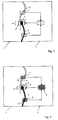
- Figure 1 is a partially block diagram top view of a device for checking and positioning a beam for machining workpieces;
- FIG. 2 shows a plan view of the device according to FIG. 1 with a schematically illustrated determination of the position of the beam.
Gemäss Figur 1 sollen zwei Werkstücke 1 und 2 miteinander durch einen Strahl 3 verbunden werden. Der Bereich der Verbindung zwischen den beiden Werkstücken 1 und 2 vor dem Strahl 3 wird als Fügelinie 4, der Bereich nach dem Strahl 3 als Schweissnaht 5 bezeichnet.According to FIG. 1, two
Der Strahl 3 kommt von einer nicht näher gezeigten Strahlquelle an einer Verschiebeeinrichtung 6, welche beispielsweise aus einem Kreuzschlitten bestehen kann. In diesem Fall ist die Verschiebeeinrichtung 6 zweidimensional in Richtung x bzw. y verschiebbar. Denkbar ist allerdings auch eine dreidimensionale Verschiebbarkeit. Wesentlich allein ist, dass durch die Verschiebeeinrichtung 6 der Strahl 3 entlang der Fügelinie 4 und auf diese ausgerichtet geführt werden kann.The
Damit der Strahl 3 entlang der Fügelinie 4 geführt werden kann, ist dem Strahl 3 ein Sensor 7 vorgeschaltet, der auch als Nahtsuchsystem bezeichnet wird. Mit diesem Sensor 7 wird der Verlauf der Fügelinie 4 laufend ermittelt und anhand der geschwindigkeitsabhängigen Verschiebezeit der Werkstücke - oder der Verschiebezeit des Strahls, falls dieser gegenüber den Werkstücken verschoben wird - der Verlauf der Fügelinie 4 über eine Steuereinheit 8 ermittelt, wobei diese Steuereinheit 8 die Verschiebeeinrichtung 6 entsprechend den Messergebnissen des Sensors 7 in Bewegung setzt, so dass der Strahl 3 immer genau auf die Fügelinie 4, bevorzugt auf eine nicht näher dargestellte Mittellinie der Fügelinie 4, gerichtet ist.So that the
Erfindungsgemäss soll dem Strahl 3 ein weiterer Sensor 9 nachgeschaltet sein, der ebenfalls mit der Steuereinheit 8 in Verbindung steht. Dieser zweite Sensor 9 beobachtet die Schweissnaht 5.According to the invention, the
Die Funktionsweise der vorliegenden Erfindung soll insbesondere beispielhaft anhand von Figur 2 beschrieben werden:The mode of operation of the present invention is to be described in particular by way of example with reference to FIG. 2:
Der Sensor 7, der dem Strahl 3 vorläuft, arbeitet dabei im sogenannten Lichschnittverfahren. Dabei wird schräg zur optischen Achse der Sensoroptik ein Streifenmuster, im vorliegenden Fall aus fünf parallelen Streifen 10 bestehend, auf den Bereich der Fügelinie 4 projiziert. Dabei verlaufen die Streifen 10 im wesentlichen quer zur Schweissnaht, können aber auch unterschiedlich beabstandet sein. Im Bereich der Fügelinie 4 werden die Streifen unterbrochen, oder es finden Versetzungen statt, die von der Sensoroptik erkannt werden. Ein Verlauf der Fügelinien kann dann anhand einer der Streifenzahl entsprechenden Anzahl von Punkten bestimmt werden.The
Gemäss Figur 2 arbeitet nach demselben Prinzip auch der zweite Sensor 9, wobei hier die Schweissnaht 5 mit entsprechendem Streifenmuster 11 ausgeleuchtet wird.According to FIG. 2, the
Weicht nun der Strahl 3 im Laufe der Zeit beispielsweise durch eine thermisch verursachte Drift von seiner durchgezogen gezeigten Position in eine gestrichelt angedeutete Position ab, so kann dies durch den Sensor 7 nicht festgestellt werden, da dieser Sensor 7 immer davon ausgeht, dass der Strahl 3 sich in Grundposition befindet. Dagegen ermittelt aber der nachfolgende Sensor 9 einen von dem vom Sensor 7 abweichenden Verlauf der Schweissnaht 5, da die der Steuereinheit 8 zugeleiteten Messergebnisse, die beispielsweise aus durch Bildanalysen gewonnenen Lagekoordinaten bestehen, nicht mehr übereinstimmen. Dies ist ebenfalls schematisch gestrichelt angedeutet. Mittels der Steuereinheit 8 wird nun die Verschiebeeinheit entsprechend dem erhaltenen Korrekturwert bewegt, so dass der Strahl 3 wieder in die Grundposition gefahren wird.If, in the course of time, the
Claims (3)
dadurch gekennzeichnet,
dass die Vorgabe oder Aufnahmeergebnisse des ersten Sensors (7) über eine Soll-Lage des Strahls (3) mit Aufnahmeergebnissen des zweiten Sensors (9) über eine Ist-Lage des Strahls (3) unter Berücksichtigung der geschwindigkeitsabhängigen relativen Verschiebung Strahl/Werkstück verglichen werden und bei einer Abweichung der Ist-Lage von der Soll-Lage der Strahl (3) auf eine Grundposition korrigiert wird.Method for checking and positioning a beam (3) for machining workpieces, a first sensor (7) (seam search system) in front of the beam or a specification determining the path to be followed by the beam (3) and a second sensor (9) after beam (3) controls the activity of the beam,
characterized,
that the specification or recording results of the first sensor (7) about a target position of the beam (3) are compared with recording results of the second sensor (9) about an actual position of the beam (3), taking into account the speed-dependent relative beam / workpiece displacement and if the actual position deviates from the target position, the beam (3) is corrected to a basic position.
Applications Claiming Priority (3)
| Application Number | Priority Date | Filing Date | Title |
|---|---|---|---|
| CH2823/95 | 1995-10-06 | ||
| CH282395 | 1995-10-06 | ||
| CH282395 | 1995-10-06 |
Publications (3)
| Publication Number | Publication Date |
|---|---|
| EP0770445A2 true EP0770445A2 (en) | 1997-05-02 |
| EP0770445A3 EP0770445A3 (en) | 1998-08-12 |
| EP0770445B1 EP0770445B1 (en) | 2001-11-07 |
Family
ID=4242408
Family Applications (1)
| Application Number | Title | Priority Date | Filing Date |
|---|---|---|---|
| EP96112931A Expired - Lifetime EP0770445B1 (en) | 1995-10-06 | 1996-08-12 | Control and positioning method of a beam or jet for machining a workpiece |
Country Status (15)
| Country | Link |
|---|---|
| US (1) | US5877960A (en) |
| EP (1) | EP0770445B1 (en) |
| JP (1) | JP2895448B2 (en) |
| KR (1) | KR100420722B1 (en) |
| CN (1) | CN1089284C (en) |
| AR (1) | AR003737A1 (en) |
| AT (1) | ATE208243T1 (en) |
| BR (1) | BR9605006A (en) |
| CA (1) | CA2183779C (en) |
| DE (1) | DE59608130D1 (en) |
| DK (1) | DK0770445T3 (en) |
| FI (1) | FI963937A (en) |
| NO (1) | NO964226L (en) |
| PL (1) | PL180628B1 (en) |
| RU (1) | RU2155654C2 (en) |
Cited By (11)
| Publication number | Priority date | Publication date | Assignee | Title |
|---|---|---|---|---|
| DE102007030395A1 (en) * | 2007-06-29 | 2009-01-02 | Trumpf Werkzeugmaschinen Gmbh + Co. Kg | Continuous laser beam welding of plate-shaped workpiece e.g. pipe along welding direction of workpiece, comprises detecting markings staggered to joint gap in workpiece in welding direction before and after the welded point at the workpiece |
| EP2022595A1 (en) * | 2007-07-23 | 2009-02-11 | Grünberger, Thomas | Method and device for configuring a processing position |
| WO2010000529A1 (en) * | 2008-07-02 | 2010-01-07 | Robert Bosch Gmbh | Motor-driven working device |
| DE102009042986B3 (en) * | 2009-09-25 | 2011-03-03 | Precitec Kg | Welding head and method for joining a workpiece |
| DE102010011253A1 (en) | 2010-03-12 | 2011-09-15 | Precitec Kg | Laser processing head and method for processing a workpiece by means of a laser beam |
| WO2012116795A1 (en) * | 2011-03-03 | 2012-09-07 | Brose Fahrzeugteile Gmbh & Co. Kommanditgesellschaft, Coburg | Method for monitoring a lateral offset of an actual weld seam configuration relative to a desired weld seam configuration, assembly and motor vehicle seat |
| DE102012204207A1 (en) | 2012-03-16 | 2013-09-19 | Trumpf Werkzeugmaschinen Gmbh + Co. Kg | Method for laser welding of workpiece sections along welding direction in joining area, involves positioning laser machining head vertically to welding direction in fixed spacing to determined position of geometric feature |
| WO2014057290A1 (en) * | 2012-10-12 | 2014-04-17 | Meta Vision Systems Limited | Methods and systems for weld control |
| DE102018008873A1 (en) | 2017-11-13 | 2019-05-16 | Matthias Sehrschön | Method and apparatus for machining a workpiece with a jet |
| DE102018217919A1 (en) * | 2018-10-19 | 2020-04-23 | Trumpf Werkzeugmaschinen Gmbh + Co. Kg | Method for determining a corrected processing head position and processing machine |
| CN112935541A (en) * | 2021-02-01 | 2021-06-11 | 西南石油大学 | Laser tracking large-scale curved plate fillet welding system and method |
Families Citing this family (26)
| Publication number | Priority date | Publication date | Assignee | Title |
|---|---|---|---|---|
| JPH09269808A (en) * | 1996-03-29 | 1997-10-14 | Fanuc Ltd | Cnc data correcting method |
| US6230072B1 (en) * | 1998-02-09 | 2001-05-08 | John W. Powell | Boiler automated welding system (BAWS) |
| KR100889061B1 (en) * | 2000-10-24 | 2009-03-16 | 엘파트로닉 아게 | Device and method for machining workpieces |
| US7081599B2 (en) | 2000-10-24 | 2006-07-25 | Elpatronic Ag | Apparatus and method for processing workpieces |
| JP3424001B2 (en) * | 2000-12-28 | 2003-07-07 | 川崎重工業株式会社 | Laser welding method and laser welding apparatus |
| DE10111662A1 (en) * | 2001-03-09 | 2002-09-26 | Thyssenkrupp Stahl Ag | Method and device for robot-controlled cutting and welding with laser radiation |
| US6766216B2 (en) * | 2001-08-27 | 2004-07-20 | Flow International Corporation | Method and system for automated software control of waterjet orientation parameters |
| KR100922478B1 (en) * | 2001-11-15 | 2009-10-21 | 프리시텍 비전 게엠베하 운트 코. 카게 | Method and device for detecting a joint between workpieces and use of the method |
| AT412456B (en) * | 2003-04-07 | 2005-03-25 | Fronius Int Gmbh | SEAM TRACKING SENSOR |
| CA2463409A1 (en) * | 2004-04-02 | 2005-10-02 | Servo-Robot Inc. | Intelligent laser joining head |
| EP1632305A1 (en) * | 2004-09-04 | 2006-03-08 | Trumpf Werkzeugmaschinen GmbH + Co. KG | Process for determining and process for adjusting the reciprocal position of the axis of a laser machining beam and the axis of a processing gas jet on a laser working machine as well as laser working machine with equipment for executing the processes |
| CN100341658C (en) * | 2005-07-04 | 2007-10-10 | 中国航空工业第一集团公司北京航空制造工程研究所 | High-energy beam welding process multi-signal fusion-monitoring instrument |
| JP2009083022A (en) * | 2007-09-28 | 2009-04-23 | Sugino Mach Ltd | Jet-stream processing device and origin correction method in jet-stream processing device |
| EP2062674B1 (en) * | 2007-11-20 | 2016-11-02 | TRUMPF Werkzeugmaschinen GmbH + Co. KG | Method for preparing and carrying out a laser welding process |
| US8600552B2 (en) | 2009-10-30 | 2013-12-03 | Honda Motor Co., Ltd. | Information processing method, apparatus, and computer readable medium |
| US8716627B2 (en) * | 2010-09-10 | 2014-05-06 | Honeywell International Inc. | Welding systems and methods |
| US9003936B2 (en) | 2011-07-29 | 2015-04-14 | Flow International Corporation | Waterjet cutting system with standoff distance control |
| RU2495737C1 (en) * | 2012-02-21 | 2013-10-20 | Федеральное государственное унитарное предприятие "Российский федеральный ядерный центр - Всероссийский научно-исследовательский институт технической физики имени академика Е.И. Забабахина" | Method of electron beam welding control |
| US9884406B2 (en) | 2014-01-15 | 2018-02-06 | Flow International Corporation | High-pressure waterjet cutting head systems, components and related methods |
| US10596717B2 (en) | 2015-07-13 | 2020-03-24 | Flow International Corporation | Methods of cutting fiber reinforced polymer composite workpieces with a pure waterjet |
| DK3292947T3 (en) * | 2016-09-07 | 2022-06-20 | Water Jet Sweden Ab | Fluid jet cutting machine and method |
| JP6831302B2 (en) | 2017-06-21 | 2021-02-17 | トヨタ自動車株式会社 | Laser processed product manufacturing method and battery manufacturing method |
| JP2022503883A (en) | 2018-09-28 | 2022-01-12 | コーニング インコーポレイテッド | Rotary light source used to modify the board |
| DE102018217487A1 (en) * | 2018-10-12 | 2020-04-16 | Trumpf Werkzeugmaschinen Gmbh + Co. Kg | Machine for cutting a plate-shaped workpiece |
| CN110773858A (en) * | 2019-11-20 | 2020-02-11 | 桂林航天工业学院 | Electron beam welding device and welding method |
| RU2763706C1 (en) * | 2021-03-16 | 2021-12-30 | федеральное государственное бюджетное образовательное учреждение высшего образования "Казанский национальный исследовательский технический университет им.А.Н. Туполева - КАИ" | Method for laser welding of dissimilar metal alloys |
Citations (3)
| Publication number | Priority date | Publication date | Assignee | Title |
|---|---|---|---|---|
| DE2608720A1 (en) * | 1976-03-03 | 1977-09-08 | Fritz Richter | Arc welding with automatic burner alignment - using optical scanner in electronic circuit which adjusts burner position |
| DE3801626C1 (en) * | 1988-01-21 | 1988-12-29 | Daimler-Benz Ag, 7000 Stuttgart, De | Rotating circular scanner, working according to the triangulation principle, as optical seam position sensor for a welding torch |
| US4916286A (en) * | 1987-01-13 | 1990-04-10 | Hitachi, Ltd. | Method and an apparatus for controlling work performed by an automatic work processing machine |
Family Cites Families (13)
| Publication number | Priority date | Publication date | Assignee | Title |
|---|---|---|---|---|
| US4199674A (en) * | 1978-12-26 | 1980-04-22 | Butler Manufacturing Company | Weld head control and guidance system |
| JPS56122673A (en) * | 1980-03-04 | 1981-09-26 | Shin Meiwa Ind Co Ltd | Location detecting sensor of groove welding line |
| JPS58107273A (en) * | 1981-12-18 | 1983-06-25 | Japan Steel & Tube Constr Co Ltd | Method and device for detecting welding arc |
| US4571479A (en) * | 1983-03-14 | 1986-02-18 | Mitsubishi Denki Kabushiki Kaisha | Welding machine with automatic seam tracking |
| US4588872A (en) * | 1984-03-22 | 1986-05-13 | Bollinger John G | Self-guided welding machine |
| JPS62114787A (en) * | 1985-11-13 | 1987-05-26 | Toyota Motor Corp | Laser beam welding device with welding position corrector |
| DE3632952A1 (en) * | 1986-09-27 | 1988-04-07 | Hoesch Ag | METHOD AND DEVICE FOR THE CONTINUOUS PRODUCTION OF TUBULAR BODIES BY LASER LENGTH SEAL WELDING |
| US4907169A (en) * | 1987-09-30 | 1990-03-06 | International Technical Associates | Adaptive tracking vision and guidance system |
| US4843287A (en) * | 1987-12-31 | 1989-06-27 | Westinghouse Electric Corp. | Path contriving system for look-ahead sensor in a robotic control system |
| DE3830892C1 (en) * | 1988-09-10 | 1989-09-28 | Fried. Krupp Gmbh, 4300 Essen, De | |
| US4831233A (en) * | 1988-09-28 | 1989-05-16 | The United States Of America As Represented By The Administrator Of The National Aeronautics And Space Administration | Optically controlled welding system |
| JPH05293648A (en) * | 1992-04-21 | 1993-11-09 | Kawasaki Steel Corp | Direct vision monitor for arc welding |
| DE4312241A1 (en) * | 1993-04-15 | 1994-10-20 | Deutsche Aerospace | Method for measuring welds (seams, welded seams) |
-
1996
- 1996-08-12 EP EP96112931A patent/EP0770445B1/en not_active Expired - Lifetime
- 1996-08-12 AT AT96112931T patent/ATE208243T1/en active
- 1996-08-12 DE DE59608130T patent/DE59608130D1/en not_active Expired - Lifetime
- 1996-08-12 DK DK96112931T patent/DK0770445T3/en active
- 1996-08-20 CA CA002183779A patent/CA2183779C/en not_active Expired - Lifetime
- 1996-08-29 US US08/706,403 patent/US5877960A/en not_active Expired - Lifetime
- 1996-09-11 RU RU96117980/02A patent/RU2155654C2/en not_active IP Right Cessation
- 1996-09-27 AR ARP960104529A patent/AR003737A1/en unknown
- 1996-10-01 KR KR1019960043430A patent/KR100420722B1/en not_active IP Right Cessation
- 1996-10-02 FI FI963937A patent/FI963937A/en not_active Application Discontinuation
- 1996-10-02 JP JP8262077A patent/JP2895448B2/en not_active Expired - Lifetime
- 1996-10-04 NO NO964226A patent/NO964226L/en not_active Application Discontinuation
- 1996-10-04 CN CN96112721A patent/CN1089284C/en not_active Expired - Lifetime
- 1996-10-04 BR BR9605006A patent/BR9605006A/en not_active IP Right Cessation
- 1996-10-04 PL PL96316402A patent/PL180628B1/en unknown
Patent Citations (3)
| Publication number | Priority date | Publication date | Assignee | Title |
|---|---|---|---|---|
| DE2608720A1 (en) * | 1976-03-03 | 1977-09-08 | Fritz Richter | Arc welding with automatic burner alignment - using optical scanner in electronic circuit which adjusts burner position |
| US4916286A (en) * | 1987-01-13 | 1990-04-10 | Hitachi, Ltd. | Method and an apparatus for controlling work performed by an automatic work processing machine |
| DE3801626C1 (en) * | 1988-01-21 | 1988-12-29 | Daimler-Benz Ag, 7000 Stuttgart, De | Rotating circular scanner, working according to the triangulation principle, as optical seam position sensor for a welding torch |
Non-Patent Citations (4)
| Title |
|---|
| PATENT ABSTRACTS OF JAPAN vol. 11, no. 333 (M-637), 30.Oktober 1987 & JP 62 114787 A (TOYOTA MOTOR CORP), 26.Mai 1987, * |
| PATENT ABSTRACTS OF JAPAN vol. 18, no. 79 (M-1557), 9.Februar 1994 & JP 05 293648 A (KAWASAKI STEEL CORP), 9.November 1993, * |
| PATENT ABSTRACTS OF JAPAN vol. 5, no. 206 (M-104), 26.Dezember 1981 & JP 56 122673 A (SHIN MEIWA IND CO LTD), 26.September 1981, * |
| PATENT ABSTRACTS OF JAPAN vol. 7, no. 211 (M-243), 17.September 1983 & JP 58 107273 A (NIHON KOUKAN KOUJI KK), 25.Juni 1983, * |
Cited By (19)
| Publication number | Priority date | Publication date | Assignee | Title |
|---|---|---|---|---|
| DE102007030395B4 (en) * | 2007-06-29 | 2010-09-30 | Trumpf Werkzeugmaschinen Gmbh + Co. Kg | Method and device for laser beam welding of a workpiece |
| DE102007030395A1 (en) * | 2007-06-29 | 2009-01-02 | Trumpf Werkzeugmaschinen Gmbh + Co. Kg | Continuous laser beam welding of plate-shaped workpiece e.g. pipe along welding direction of workpiece, comprises detecting markings staggered to joint gap in workpiece in welding direction before and after the welded point at the workpiece |
| EP2022595A1 (en) * | 2007-07-23 | 2009-02-11 | Grünberger, Thomas | Method and device for configuring a processing position |
| WO2010000529A1 (en) * | 2008-07-02 | 2010-01-07 | Robert Bosch Gmbh | Motor-driven working device |
| DE102009042986B3 (en) * | 2009-09-25 | 2011-03-03 | Precitec Kg | Welding head and method for joining a workpiece |
| WO2011035913A1 (en) | 2009-09-25 | 2011-03-31 | Precitec Kg | Welding head and method for joining a workpiece |
| US10092977B2 (en) | 2009-09-25 | 2018-10-09 | Precitec Gmbh & Co. Kg | Welding head and method for joining a workpiece |
| US9259801B2 (en) | 2010-03-12 | 2016-02-16 | Precitec Kg | Laser processing head and method for processing a workpiece by means of a laser beam |
| DE102010011253A1 (en) | 2010-03-12 | 2011-09-15 | Precitec Kg | Laser processing head and method for processing a workpiece by means of a laser beam |
| WO2011110357A1 (en) | 2010-03-12 | 2011-09-15 | Precitec Kg | Laser processing head and method for processing a workpiece by means of a laser beam |
| DE102010011253B4 (en) * | 2010-03-12 | 2013-07-11 | Precitec Kg | Laser processing head, robot apparatus and method for processing a workpiece by means of a laser beam |
| WO2012116795A1 (en) * | 2011-03-03 | 2012-09-07 | Brose Fahrzeugteile Gmbh & Co. Kommanditgesellschaft, Coburg | Method for monitoring a lateral offset of an actual weld seam configuration relative to a desired weld seam configuration, assembly and motor vehicle seat |
| US9649726B2 (en) | 2011-03-03 | 2017-05-16 | Brose Fahrzeugteile Gmbh & Co., Kommanditgesellschaft, Coburg | Method for monitoring a lateral offset of an actual weld seam configuration relative to a desired weld seam configuration, assembly and motor vehicle seat |
| DE102012204207B4 (en) * | 2012-03-16 | 2015-02-19 | Trumpf Werkzeugmaschinen Gmbh + Co. Kg | Method for laser beam welding |
| DE102012204207A1 (en) | 2012-03-16 | 2013-09-19 | Trumpf Werkzeugmaschinen Gmbh + Co. Kg | Method for laser welding of workpiece sections along welding direction in joining area, involves positioning laser machining head vertically to welding direction in fixed spacing to determined position of geometric feature |
| WO2014057290A1 (en) * | 2012-10-12 | 2014-04-17 | Meta Vision Systems Limited | Methods and systems for weld control |
| DE102018008873A1 (en) | 2017-11-13 | 2019-05-16 | Matthias Sehrschön | Method and apparatus for machining a workpiece with a jet |
| DE102018217919A1 (en) * | 2018-10-19 | 2020-04-23 | Trumpf Werkzeugmaschinen Gmbh + Co. Kg | Method for determining a corrected processing head position and processing machine |
| CN112935541A (en) * | 2021-02-01 | 2021-06-11 | 西南石油大学 | Laser tracking large-scale curved plate fillet welding system and method |
Also Published As
| Publication number | Publication date |
|---|---|
| AR003737A1 (en) | 1998-09-09 |
| CN1089284C (en) | 2002-08-21 |
| ATE208243T1 (en) | 2001-11-15 |
| PL316402A1 (en) | 1997-04-14 |
| US5877960A (en) | 1999-03-02 |
| CA2183779A1 (en) | 1997-04-07 |
| DK0770445T3 (en) | 2002-02-18 |
| EP0770445A3 (en) | 1998-08-12 |
| NO964226L (en) | 1997-04-07 |
| JPH09126726A (en) | 1997-05-16 |
| KR100420722B1 (en) | 2004-05-24 |
| FI963937A (en) | 1997-04-07 |
| FI963937A0 (en) | 1996-10-02 |
| KR970022336A (en) | 1997-05-28 |
| CA2183779C (en) | 2007-06-19 |
| RU2155654C2 (en) | 2000-09-10 |
| JP2895448B2 (en) | 1999-05-24 |
| NO964226D0 (en) | 1996-10-04 |
| EP0770445B1 (en) | 2001-11-07 |
| MX9604523A (en) | 1997-07-31 |
| CN1154283A (en) | 1997-07-16 |
| DE59608130D1 (en) | 2001-12-13 |
| BR9605006A (en) | 1998-06-23 |
| PL180628B1 (en) | 2001-03-30 |
Similar Documents
| Publication | Publication Date | Title |
|---|---|---|
| EP0770445B1 (en) | Control and positioning method of a beam or jet for machining a workpiece | |
| EP3710196B1 (en) | Laser machining system and method for laser machining | |
| EP2544849B1 (en) | Laser machning head und method of machining a workpiece using a laser beam | |
| EP1979124B1 (en) | Laser beam welding head, its use and beam welding method | |
| EP0367924B1 (en) | Procedure and apparatus for determing the position of a seam for laser welding | |
| EP1099506B1 (en) | Method and device for measuring process parameters of a material machining process | |
| DE102013219220A1 (en) | Method for laser remote processing of a workpiece on a throat and device therefor | |
| EP1904260A1 (en) | Method and device for determining the lateral relative displacement between a processing head and a workpiece | |
| DE102015015330B4 (en) | Processing device and method for monitoring a processing process carried out with a processing device | |
| DE102017115922C5 (en) | Method and device for measuring and setting a distance between a machining head and a workpiece and associated method for regulation | |
| DE102016001661B3 (en) | Measuring device and method for determining a relative inclination of a workpiece by means of optical coherence tomography during processing | |
| EP0817698B1 (en) | Continuous butt-welding process and device for metal sheets, in particular for building car bodies in the car industry | |
| DE102010005896A1 (en) | Laser welding robot for connecting components by a welding seam, comprises a laser welding device arranged on an arm of the robot, a coupling device for laser radiation, a laser head and an electronic control | |
| EP2418040B1 (en) | Method of controlling a device for laser welding | |
| DE102016014564A1 (en) | Measuring device for monitoring a machining process using measurement information acquired at different measuring positions | |
| DE102008027393A1 (en) | Optical monitoring device | |
| EP1395385A1 (en) | Method and device for the robot-controlled cutting of workpieces to be assembled by means of laser radiation | |
| DE102017010055A1 (en) | Laser beam welding of geometric figures with OCT seam guide | |
| EP2091699B1 (en) | Method and device for fine-positioning a tool having a handling device | |
| DE4026759A1 (en) | LASER WELDING SYSTEM WORKING WITH WELDING SHOCK TRACKING | |
| EP1238746A2 (en) | Method and device for robotically controlled laser cutting and welding | |
| DE202014105648U1 (en) | Device for joining workpieces to a lap joint | |
| WO2014012610A1 (en) | Method and device for contactless distance measurement | |
| EP1399287B1 (en) | Method for laser-cutting structural components to be joined | |
| DE102012204207B4 (en) | Method for laser beam welding |
Legal Events
| Date | Code | Title | Description |
|---|---|---|---|
| PUAI | Public reference made under article 153(3) epc to a published international application that has entered the european phase |
Free format text: ORIGINAL CODE: 0009012 |
|
| AK | Designated contracting states |
Kind code of ref document: A2 Designated state(s): AT BE CH DE DK LI NL SE |
|
| PUAL | Search report despatched |
Free format text: ORIGINAL CODE: 0009013 |
|
| AK | Designated contracting states |
Kind code of ref document: A3 Designated state(s): AT BE CH DE DK LI NL SE |
|
| 17P | Request for examination filed |
Effective date: 19990212 |
|
| RAP3 | Party data changed (applicant data changed or rights of an application transferred) |
Owner name: ELPATRONIC AG |
|
| GRAG | Despatch of communication of intention to grant |
Free format text: ORIGINAL CODE: EPIDOS AGRA |
|
| 17Q | First examination report despatched |
Effective date: 20010125 |
|
| GRAG | Despatch of communication of intention to grant |
Free format text: ORIGINAL CODE: EPIDOS AGRA |
|
| GRAH | Despatch of communication of intention to grant a patent |
Free format text: ORIGINAL CODE: EPIDOS IGRA |
|
| GRAH | Despatch of communication of intention to grant a patent |
Free format text: ORIGINAL CODE: EPIDOS IGRA |
|
| GRAA | (expected) grant |
Free format text: ORIGINAL CODE: 0009210 |
|
| AK | Designated contracting states |
Kind code of ref document: B1 Designated state(s): AT BE CH DE DK LI NL SE |
|
| REF | Corresponds to: |
Ref document number: 208243 Country of ref document: AT Date of ref document: 20011115 Kind code of ref document: T |
|
| REG | Reference to a national code |
Ref country code: CH Ref legal event code: EP |
|
| REF | Corresponds to: |
Ref document number: 59608130 Country of ref document: DE Date of ref document: 20011213 |
|
| REG | Reference to a national code |
Ref country code: DK Ref legal event code: T3 |
|
| PLBE | No opposition filed within time limit |
Free format text: ORIGINAL CODE: 0009261 |
|
| STAA | Information on the status of an ep patent application or granted ep patent |
Free format text: STATUS: NO OPPOSITION FILED WITHIN TIME LIMIT |
|
| 26N | No opposition filed | ||
| PGFP | Annual fee paid to national office [announced via postgrant information from national office to epo] |
Ref country code: NL Payment date: 20080813 Year of fee payment: 13 Ref country code: DK Payment date: 20080814 Year of fee payment: 13 |
|
| REG | Reference to a national code |
Ref country code: CH Ref legal event code: PUE Owner name: PRECITEC VISION GMBH & CO. KG Free format text: SOUTEC SOUDRONIC AG#ROTFARB 3#8413 NEFTENBACH (CH) -TRANSFER TO- PRECITEC VISION GMBH & CO. KG#UNTERORTSTRASSE 48#65760 ESCHBORN (DE) Ref country code: CH Ref legal event code: PUE Owner name: SOUDRONIC AG Free format text: ELPATRONIC AG#INDUSTRIESTRASSE 35#8962 BERGDIETIKON (CH) -TRANSFER TO- SOUDRONIC AG#INDUSTRIESTRASSE 35#8962 BERGDIETIKON (CH) Ref country code: CH Ref legal event code: PUE Owner name: SOUTEC SOUDRONIC AG Free format text: SOUDRONIC AG#INDUSTRIESTRASSE 35#8962 BERGDIETIKON (CH) -TRANSFER TO- SOUTEC SOUDRONIC AG#ROTFARB 3#8413 NEFTENBACH (CH) Ref country code: CH Ref legal event code: NV Representative=s name: E. BLUM & CO. AG PATENT- UND MARKENANWAELTE VSP |
|
| PGFP | Annual fee paid to national office [announced via postgrant information from national office to epo] |
Ref country code: BE Payment date: 20080918 Year of fee payment: 13 |
|
| BECA | Be: change of holder's address |
Owner name: PRECITEC VISION G.M.B.H. & CO. K.G.UNTERORTSTRASSE Effective date: 20090219 |
|
| BECH | Be: change of holder |
Owner name: PRECITEC VISION G.M.B.H. & CO. K.G.UNTERORTSTRASSE Effective date: 20090219 Owner name: PRECITEC VISION G.M.B.H. & CO. K.G. Effective date: 20090219 |
|
| BERE | Be: lapsed |
Owner name: PRECITEC VISION G.M.B.H. & CO. K.G. Effective date: 20090831 |
|
| REG | Reference to a national code |
Ref country code: NL Ref legal event code: V1 Effective date: 20100301 Ref country code: CH Ref legal event code: NV Representative=s name: BOHEST AG |
|
| REG | Reference to a national code |
Ref country code: DK Ref legal event code: EBP |
|
| PG25 | Lapsed in a contracting state [announced via postgrant information from national office to epo] |
Ref country code: BE Free format text: LAPSE BECAUSE OF NON-PAYMENT OF DUE FEES Effective date: 20090831 |
|
| PG25 | Lapsed in a contracting state [announced via postgrant information from national office to epo] |
Ref country code: NL Free format text: LAPSE BECAUSE OF NON-PAYMENT OF DUE FEES Effective date: 20100301 Ref country code: DK Free format text: LAPSE BECAUSE OF NON-PAYMENT OF DUE FEES Effective date: 20090831 |
|
| REG | Reference to a national code |
Ref country code: CH Ref legal event code: PCAR Free format text: NEW ADDRESS: HOLBEINSTRASSE 36-38, 4051 BASEL (CH) |
|
| PGFP | Annual fee paid to national office [announced via postgrant information from national office to epo] |
Ref country code: CH Payment date: 20150824 Year of fee payment: 20 Ref country code: DE Payment date: 20150825 Year of fee payment: 20 |
|
| PGFP | Annual fee paid to national office [announced via postgrant information from national office to epo] |
Ref country code: SE Payment date: 20150824 Year of fee payment: 20 Ref country code: AT Payment date: 20150820 Year of fee payment: 20 |
|
| REG | Reference to a national code |
Ref country code: DE Ref legal event code: R071 Ref document number: 59608130 Country of ref document: DE |
|
| REG | Reference to a national code |
Ref country code: CH Ref legal event code: PL |
|
| REG | Reference to a national code |
Ref country code: SE Ref legal event code: EUG |
|
| REG | Reference to a national code |
Ref country code: AT Ref legal event code: MK07 Ref document number: 208243 Country of ref document: AT Kind code of ref document: T Effective date: 20160812 |