EP0770219B1 - Optisches messgerat und verfahren - Google Patents
Optisches messgerat und verfahren Download PDFInfo
- Publication number
- EP0770219B1 EP0770219B1 EP95924875A EP95924875A EP0770219B1 EP 0770219 B1 EP0770219 B1 EP 0770219B1 EP 95924875 A EP95924875 A EP 95924875A EP 95924875 A EP95924875 A EP 95924875A EP 0770219 B1 EP0770219 B1 EP 0770219B1
- Authority
- EP
- European Patent Office
- Prior art keywords
- light
- diffracting
- structures
- detector
- light source
- Prior art date
- Legal status (The legal status is an assumption and is not a legal conclusion. Google has not performed a legal analysis and makes no representation as to the accuracy of the status listed.)
- Expired - Lifetime
Links
- 230000003287 optical effect Effects 0.000 title claims description 150
- 238000000691 measurement method Methods 0.000 title 1
- 238000000034 method Methods 0.000 claims description 131
- 238000010168 coupling process Methods 0.000 claims description 52
- 238000005859 coupling reaction Methods 0.000 claims description 52
- 238000005259 measurement Methods 0.000 claims description 49
- 238000012545 processing Methods 0.000 claims description 44
- 239000007788 liquid Substances 0.000 claims description 39
- 239000000758 substrate Substances 0.000 claims description 37
- 230000005693 optoelectronics Effects 0.000 claims description 31
- 230000008878 coupling Effects 0.000 claims description 26
- 239000004065 semiconductor Substances 0.000 claims description 24
- 238000006073 displacement reaction Methods 0.000 claims description 21
- 230000005855 radiation Effects 0.000 claims description 18
- 230000005540 biological transmission Effects 0.000 claims description 17
- 239000000463 material Substances 0.000 claims description 15
- 239000002245 particle Substances 0.000 claims description 12
- 238000009826 distribution Methods 0.000 claims description 8
- 230000003993 interaction Effects 0.000 claims description 8
- 238000002156 mixing Methods 0.000 claims description 6
- 238000002296 dynamic light scattering Methods 0.000 claims description 4
- 238000002366 time-of-flight method Methods 0.000 claims description 4
- 238000006243 chemical reaction Methods 0.000 claims description 2
- 239000007789 gas Substances 0.000 description 36
- 230000005670 electromagnetic radiation Effects 0.000 description 26
- 238000001514 detection method Methods 0.000 description 22
- 238000002310 reflectometry Methods 0.000 description 15
- 230000001427 coherent effect Effects 0.000 description 13
- 108010025899 gelatin film Proteins 0.000 description 12
- 108010010803 Gelatin Proteins 0.000 description 11
- 230000000875 corresponding effect Effects 0.000 description 11
- 239000008273 gelatin Substances 0.000 description 11
- 229920000159 gelatin Polymers 0.000 description 11
- 235000019322 gelatine Nutrition 0.000 description 11
- 235000011852 gelatine desserts Nutrition 0.000 description 11
- 239000000243 solution Substances 0.000 description 8
- 230000004075 alteration Effects 0.000 description 7
- 238000004519 manufacturing process Methods 0.000 description 7
- 230000003746 surface roughness Effects 0.000 description 7
- KFZMGEQAYNKOFK-UHFFFAOYSA-N Isopropanol Chemical compound CC(C)O KFZMGEQAYNKOFK-UHFFFAOYSA-N 0.000 description 6
- 238000002360 preparation method Methods 0.000 description 5
- 239000007787 solid Substances 0.000 description 5
- XLYOFNOQVPJJNP-UHFFFAOYSA-N water Substances O XLYOFNOQVPJJNP-UHFFFAOYSA-N 0.000 description 5
- 238000012937 correction Methods 0.000 description 4
- 230000001419 dependent effect Effects 0.000 description 4
- 238000013461 design Methods 0.000 description 4
- 150000002500 ions Chemical class 0.000 description 4
- 238000003756 stirring Methods 0.000 description 4
- 230000008901 benefit Effects 0.000 description 3
- 230000000694 effects Effects 0.000 description 3
- 239000010410 layer Substances 0.000 description 3
- 230000009467 reduction Effects 0.000 description 3
- 238000011160 research Methods 0.000 description 3
- 238000013519 translation Methods 0.000 description 3
- XKRFYHLGVUSROY-UHFFFAOYSA-N Argon Chemical compound [Ar] XKRFYHLGVUSROY-UHFFFAOYSA-N 0.000 description 2
- 229910001218 Gallium arsenide Inorganic materials 0.000 description 2
- 239000007864 aqueous solution Substances 0.000 description 2
- 238000012993 chemical processing Methods 0.000 description 2
- 230000001143 conditioned effect Effects 0.000 description 2
- 230000001747 exhibiting effect Effects 0.000 description 2
- 239000011521 glass Substances 0.000 description 2
- 239000004848 polyfunctional curative Substances 0.000 description 2
- 239000011241 protective layer Substances 0.000 description 2
- 230000035945 sensitivity Effects 0.000 description 2
- 239000004332 silver Substances 0.000 description 2
- 229910052709 silver Inorganic materials 0.000 description 2
- -1 silver halide Chemical class 0.000 description 2
- 230000003595 spectral effect Effects 0.000 description 2
- 241001479434 Agfa Species 0.000 description 1
- 229910002621 H2PtCl6 Inorganic materials 0.000 description 1
- 230000001133 acceleration Effects 0.000 description 1
- 239000004411 aluminium Substances 0.000 description 1
- XAGFODPZIPBFFR-UHFFFAOYSA-N aluminium Chemical compound [Al] XAGFODPZIPBFFR-UHFFFAOYSA-N 0.000 description 1
- 229910052782 aluminium Inorganic materials 0.000 description 1
- JOSWYUNQBRPBDN-UHFFFAOYSA-P ammonium dichromate Chemical compound [NH4+].[NH4+].[O-][Cr](=O)(=O)O[Cr]([O-])(=O)=O JOSWYUNQBRPBDN-UHFFFAOYSA-P 0.000 description 1
- 230000003321 amplification Effects 0.000 description 1
- 238000004458 analytical method Methods 0.000 description 1
- 239000007900 aqueous suspension Substances 0.000 description 1
- 229910052786 argon Inorganic materials 0.000 description 1
- 230000008859 change Effects 0.000 description 1
- 239000003795 chemical substances by application Substances 0.000 description 1
- 239000003086 colorant Substances 0.000 description 1
- 238000004040 coloring Methods 0.000 description 1
- 230000002596 correlated effect Effects 0.000 description 1
- 239000006059 cover glass Substances 0.000 description 1
- 230000003247 decreasing effect Effects 0.000 description 1
- 239000008367 deionised water Substances 0.000 description 1
- 238000011161 development Methods 0.000 description 1
- 230000009977 dual effect Effects 0.000 description 1
- 230000005672 electromagnetic field Effects 0.000 description 1
- 239000000839 emulsion Substances 0.000 description 1
- 229920006335 epoxy glue Polymers 0.000 description 1
- 238000007687 exposure technique Methods 0.000 description 1
- 239000000499 gel Substances 0.000 description 1
- 239000002241 glass-ceramic Substances 0.000 description 1
- 239000003292 glue Substances 0.000 description 1
- 230000005484 gravity Effects 0.000 description 1
- 230000010354 integration Effects 0.000 description 1
- 238000004599 local-density approximation Methods 0.000 description 1
- 238000007620 mathematical function Methods 0.000 description 1
- 239000000203 mixture Substances 0.000 description 1
- 238000003199 nucleic acid amplification method Methods 0.000 description 1
- 239000011148 porous material Substances 0.000 description 1
- 230000008569 process Effects 0.000 description 1
- 230000001681 protective effect Effects 0.000 description 1
- 231100000489 sensitizer Toxicity 0.000 description 1
- 238000000926 separation method Methods 0.000 description 1
- 230000008961 swelling Effects 0.000 description 1
- 230000001131 transforming effect Effects 0.000 description 1
- 238000000827 velocimetry Methods 0.000 description 1
Images


Classifications
-
- G—PHYSICS
- G01—MEASURING; TESTING
- G01S—RADIO DIRECTION-FINDING; RADIO NAVIGATION; DETERMINING DISTANCE OR VELOCITY BY USE OF RADIO WAVES; LOCATING OR PRESENCE-DETECTING BY USE OF THE REFLECTION OR RERADIATION OF RADIO WAVES; ANALOGOUS ARRANGEMENTS USING OTHER WAVES
- G01S7/00—Details of systems according to groups G01S13/00, G01S15/00, G01S17/00
- G01S7/48—Details of systems according to groups G01S13/00, G01S15/00, G01S17/00 of systems according to group G01S17/00
- G01S7/481—Constructional features, e.g. arrangements of optical elements
- G01S7/4811—Constructional features, e.g. arrangements of optical elements common to transmitter and receiver
-
- G—PHYSICS
- G01—MEASURING; TESTING
- G01P—MEASURING LINEAR OR ANGULAR SPEED, ACCELERATION, DECELERATION, OR SHOCK; INDICATING PRESENCE, ABSENCE, OR DIRECTION, OF MOVEMENT
- G01P3/00—Measuring linear or angular speed; Measuring differences of linear or angular speeds
- G01P3/36—Devices characterised by the use of optical means, e.g. using infrared, visible, or ultraviolet light
- G01P3/366—Devices characterised by the use of optical means, e.g. using infrared, visible, or ultraviolet light by using diffraction of light
-
- G—PHYSICS
- G01—MEASURING; TESTING
- G01S—RADIO DIRECTION-FINDING; RADIO NAVIGATION; DETERMINING DISTANCE OR VELOCITY BY USE OF RADIO WAVES; LOCATING OR PRESENCE-DETECTING BY USE OF THE REFLECTION OR RERADIATION OF RADIO WAVES; ANALOGOUS ARRANGEMENTS USING OTHER WAVES
- G01S17/00—Systems using the reflection or reradiation of electromagnetic waves other than radio waves, e.g. lidar systems
- G01S17/02—Systems using the reflection of electromagnetic waves other than radio waves
- G01S17/50—Systems of measurement based on relative movement of target
- G01S17/58—Velocity or trajectory determination systems; Sense-of-movement determination systems
-
- G—PHYSICS
- G01—MEASURING; TESTING
- G01S—RADIO DIRECTION-FINDING; RADIO NAVIGATION; DETERMINING DISTANCE OR VELOCITY BY USE OF RADIO WAVES; LOCATING OR PRESENCE-DETECTING BY USE OF THE REFLECTION OR RERADIATION OF RADIO WAVES; ANALOGOUS ARRANGEMENTS USING OTHER WAVES
- G01S7/00—Details of systems according to groups G01S13/00, G01S15/00, G01S17/00
- G01S7/48—Details of systems according to groups G01S13/00, G01S15/00, G01S17/00 of systems according to group G01S17/00
- G01S7/497—Means for monitoring or calibrating
Definitions
- the present invention relates to a method and an apparatus for the determination of a condition or state of an object based on quasi-elastic interaction between the object and light transmitted to the object where light is transmitted to the object from a light source through an optical structure and light that has interacted with the object is collected and detected.
- Prior art methods and apparatus of the above kind are based on the use of various conventional refractive elements such as beam splitters, refractive lenses and prisms, and birefringent elements, and suffer from a number of disadvantages.
- One of the disadvantages is that the conventional refractive elements refracting the electromagnetic radiation are bulky and often difficult to adjust, and since a relatively large number of elements is required, the prior art apparatus of the above kind is relatively large, and expensive to manufacture.
- Yet another disadvantage is that use of bulky conventional refractive elements for beam splitting usually leads to unequal path lengths for the splitted beams, the difference often being in the order of centimetres, which makes it necessary to use light sources with a long coherence length, such as gas lasers, when coherent detection is needed.
- Still another disadvantage is that since the refractive properties of conventional refractive elements are sensitive to ambient conditions, e.g. temperature, humidity, vibrations, etc., the determination is dependent on ambient conditions.
- gas lasers are bulky and expensive and require large, bulky, and expensive power supplies.
- the emitted energy of the laser can shift between different modes so that the light intensity at different wavelengths varies up and down and in some instances a 100 % modulation of the laser light has been seen leading to severe signal variations in the measurement apparatus.
- a time-of-flight laser anemometer comprising means to split a laser beam into two angular beams of orthogonal polarization, means for expanding and focusing the beam into two focal spots in the measuring volume, means for collecting light and imaging enlarged scatterings from the focal spots at two pinholes in front of two detectors, and means for cross-correlating signals of the two detectors.
- a holographic optical element is used to diffract two light beams onto two spots on the object.
- the rotation of the object causes the light from the two spots scattered by the surface of the object to be Doppler shifted.
- the difference between the Doppler shifts of the light scattered from the two spots on the object indicates the rotational speed of the object.
- Lars Lading et al. "Analysis of a surface-scattering spectrometer", Journal of the Optical Society of America, Vol. 6, No. 11, November 1989, discloses an apparatus for measuring the spatial and temporal statistics of surface fluctuations, in particular, thermally excited capillary waves on liquid surfaces.
- an optical device for determination of surface velocity of a moving object e.g., a bar code during scanning
- the device comprises a diffractive optical element for focusing two beams of light incident upon it on two regions of the object. The distance between the two regions are independent of the distance between the device and the object but it is wavelength dependent.
- a miniaturized apparatus for measurement of distance and angle comprises an integrated optical device with a first diffracting region for diffraction of a light beam into a diffracted beam bundle.
- the beam bundle impinges on a diffracting means of the apparatus directing the beam bundle to perpendicularly impinge upon second and third diffracting regions of the integrated optical device.
- the second and third diffracting regions comprise circular gratings that are easy to manufacture and that couple the beam bundles into planar respective waveguides of the integrated optical device for transmission to a coupler of the device in which the light bundles interfere with each other so that their phase relationship can be detected by detectors included in the integrated optical device.
- the present invention is based on intensive research in the field of optical measurement apparatuses of the above kind, comprising research in different configurations of the measurement apparatuses, in different components of the measurement apparatuses, such as optical components, electronic components, mechanical components, etc., in different signal processing techniques of the measurement apparatuses, such as photon statistics and correlation, frequency and phase determination of detector signals, such as photon currents, diode currents, etc.
- diffracting structure(s) of the diffractive optical element can be designed so that the determinations obtained by the use of the measurement apparatus is substantially independent of the wavelength of the light source or sources of the measurement apparatus.
- the wavelength of the semiconductor lasers varies considerably, often 5 %, from one sample to the other and further the wavelength of each sample varies as a function of temperature, typically the temperature drift is 0.25 nm per °C.
- the diffractive optical element is designed so that determinations obtained by the use of the measurement apparatus is substantially independent of the wavelength of the light source, the semiconductor lasers can be used without affecting the accuracy of the determinations.
- the semiconductor lasers have several improved qualities compared to gas lasers, such as noise qualities, mode qualities, size, price, etc.
- a GaAs laser supplied from a battery has intensity fluctuations below 0.01% while a gas laser is specified to have fluctuations below 1%.
- the signal to laser noise ratio can be improved up to 60 dB by the use of semiconductor lasers instead of gas lasers.
- Another advantageous feature of the diffractive optical element that facilitates the use of semiconductor lasers is that it is possible to design the element to cope with the coherence length of the light source of the apparatus.
- the path length differences of different beams of the measurement apparatus are less than the coherence length of the light source.
- the path length differences are of the order of millimetres to centimetres while the path length differences obtained when a diffractive optical element is used without difficulty can be designed to be less than one wavelength.
- the use of diffractive optical elements reduces the coherence requirements of the light sources used in the measurement apparatus as there is substantially no need for longitudinal coherence while good transversal coherence is still needed.
- the occurrence of a number of modes as in a gas laser can reduce both the transversal and the longitudinal coherence while the requirement of the measurement apparatus of transversal coherence is easily fulfilled by a semiconductor laser.
- diffractive optical element it is possible to integrate several diffracting structures in one diffractive optical element, thereby integrating several optical functions, such as lenses, beam splitters, etc. in one optical component.
- the possibility of integrating several optical functions in one diffractive element makes it possible to implement optical functions which can not be implemented with classical optical components as the physical size of these components restricts the possibilities of positioning of the components, e.g. it is not possible to create two parallel light beams of equal polarisation with an arbitrary small distance between them using classical optical components.
- the above mentioned objects are fulfilled by providing a method with the above mentioned advantages for the determination of a condition or state of an object based on quasi-elastic interaction between the object and light transmitted to the object, comprising transmitting the light to the object from a light source through at least one diffractive optical element and collecting and detecting light that has interacted with the object, each of the at least one diffractive optical element incorporating at least one diffracting region, the at least one diffractive optical element defining both the functional principle of the method and the calibration of the method, in such a way that both the functional principle and the calibration are substantially exclusively defined by the at least one diffractive optical element, characterized in that the diffracting region comprises at least two diffracting structures laterally displaced relative to each other and designed so that the axes of the transmitted beams radiated by the at least two diffracting structures, respectively, are substantially parallel and the spacing between the axes is substantially independent of the wavelength of the light source and/or that the angle between intersecting beams radiated by at least one
- an apparatus for carrying out the method above comprising a light source for generating a beam of light, a receiver means for collecting and detecting light that has interacted with the object, a beam transmission means for the transmission of light from the light source to the object comprising at least one diffractive optical element each of which comprises at least one diffracting region, the at least one diffractive optical element defining both the function and the calibration of the apparatus in such a way that both the function and the calibration are substantially exclusively defined by the at least one diffractive optical element characterized in that the diffracting region comprises at least two diffracting structures laterally displaced relative to each other and designed so that the axes of the transmitted beams radiated by the at least two diffracting structures, respectively, are substantially parallel and the spacing between the axes is substantially independent of the wavelength of the light source and/or that the angle between intersecting beams radiated by at least one diffracting region depends on the wavelength in such a way that the resulting calibration of the method is substantially independent of the wavelength of the light
- a condition or state of an object designates any macroscopic condition or state of the object, such as size, form, colour, temperature, position, velocity, acceleration, rotation, vibration, deformation, viscosity, tension, etc.
- quasi-elastic interaction designates any macroscopic interaction between light incident on an object and the object that do not lead to any changes in the quantum energies of the molecules of the object, such as reflection, refraction, scattering, diffraction, etc. of the incident light.
- a diffractive optical element is an optical device that diffracts light.
- a diffracting region is an area of a diffractive optical element containing diffracting structures.
- a diffracting region is surrounded by diffracting structure free regions.
- a diffracting structure is a pattern of refractive index variations or of surface relief structures on a scale much smaller than the illuminated area.
- a diffracting structure can be designed with specific desired optical functions, such as the optical function of a specific lens, a beamsplitter, an integration of classical optical components, a mathematical function, etc.
- Several diffracting structures may or may not overlap partly or fully in a diffracting region of a diffractive optical element.
- the expression "mixing" is intended to mean a coherent superposition of the electromagnetic fields in such a way that the photodetector output contains spectral components at the different frequencies of the superposed fields.
- the expression "scattered radiation” is intended to mean a pertubated wave front of the radiation with which an object interacts which wavefront is altered or changed in such a way that the far field comprises a large solid angle, i.e. a solid angle much larger than the far field solid angle of the unperturbed radiation.
- This scattering may be caused by rough surfaces, by small particles, or by other kinds of refractive index structures.
- diffracted radiation is intended to mean a pertubated wave front the perturbation of which is caused by a collection of diffracting structure.
- spatial scale is intended to designate the characteristic length within which the reflectivity or roughness exhibits little change. Two points on a surface with a mutual spacing smaller than the spatial scale will most likely have the same reflectivity or height deviation. With a much larger spacing there is no correlation between reflectivities or height deviations.
- the number of conventional refractive elements such as beam splitters, lenses, etc., for processing the electromagnetic radiation can be reduced, or even avoided, it is ensured that the apparatus is relatively simple to assemble, and thereby that the cost of manufacture of the apparatus is relatively low.
- one aspect of the invention relates to methods and apparatuses utilizing parallel light beams transmitted to the object, such as methods and apparatuses of time-of-flight velocimetry, where the diffracting structures have been designed so that the parallel light beams emerging from the diffracting structures stays parallel independently of the wavelength of the light source and the distance between the parallel light beams also stays constant, independent of the wavelength of the light source.
- a measurement of the time for an object to pass from one of the parallel light beams to the other is independent of the position of the object along the beams and independent of the wavelength of the light source.
- Another aspect of the invention relates to methods and apparatuses utilizing crossing light beams, such as methods and apparatuses of Laser Doppler Velocimetry, where the diffracting structures have been designed so that the angle between the crossing light beams emerging from the diffracting structures varies as a specific function of the wavelength of the light source in such a way that a measurement of the difference in Doppler shift of an object that passes the crossing point of the two crossing beams is independent of the wavelength of the light source as the variation of the angle between the crossing beams as a function of the wavelength of the light source compensates for the variation of the difference in Doppler shift as a function of the wavelength of the light source.
- the splitting and direction of the electromagnetic radiation onto two spatially separated regions of the object by diffraction is performed by partly overlapping two diffracting structures having a relative displacement equal to the spacing between the two spatially separated regions of the object, and by providing substantially parallel axes of the two beams.
- the diffracting structures provide substantially parallel axes of the two beams in the two regions of the object, the wavelength dependence is the same for both focused beams whereby it is ensured that the determination is independent of the wavelength, e.g. small changes of the wavelength have no impact on the spacing between the two beams even if the measuring volume is slightly displaced.
- the diffractive elements of the transmitter means comprise two partly overlapping diffracting structures having a relative displacement equal to the spacing between the two spatially separated regions of the object, and providing substantially parallel axes of the two beams.
- the two partially overlapping diffracting structures ensure that the determinations are independent of the wavelength of the electromagnetic radiation.
- the diffractive elements of the transmitter means comprise two overlapping diffracting structures having a relative displacement shorter than the spacing between the two spatially separated regions on the object, preferably two fully overlapping diffracting structures and providing substantially non-parallel axes of the two beams.
- the larger overlap between the diffracting structures ensures that a larger fraction of the beam of the electromagnetic radiation is utilized compared to an overlap of the two overlapping diffracting structures having a relative displacement equal to the spacing between the two spatially separated regions of the object.
- the determination is dependent on the wavelength of the electromagnetic radiation and on the distance to the object.
- a further advantage of the embodiment comprising fully overlapping diffracting structures is a simpler manufacturing procedure.
- the beam generation means is wavelength stabilized, e.g. such as for a wavelength stabilized laser.
- the receiver means may consist of any suitable radiation collecting means for collecting the scattered or diffracted radiation from the object, and of any suitable radiation focusing means for directing the collected, scattered or diffracted radiation onto the detector means.
- the collection and direction of the scattered or diffracted radiation is performed by at least one diffracting structure.
- the collection and direction of the scattered or diffracted radiation is performed by fully or partly overlapping two diffracting structures.
- the diffractive elements of the receiver means comprise two fully or two partly overlapping diffracting structures whereby it is obtained that the receiver means are realized to allow for a robust, compact apparatus.
- both the transmitter means and the receiver means comprise diffractive elements having suitable diffracting structures.
- the coherent detection mode, the two partly overlapping, diffracting structures of the receiver means and the transmitter means, respectively have the same relative position and the same apertures whereby the cross correlation between the generated detector signals from the two regions of the object is maximized, and the generated detector signals are dominated by the effects of the surface roughness or cross particle components.
- the detector signal bandwidth is determined by the reciprocal value of the transit time which it takes the object element to pass one beam.
- the modulation of the detector signals may be close to unity.
- the coherent detection mode is particularly useful for objects where the surface or the measuring volume is able to generate fully developed speckle patterns.
- the detection may be formed by redirecting the collected light into the laser and, thus, using the laser also as a parametric amplifier.
- a detector signal may then be generated by measuring the laser light output or the laser drive current.
- the apertures of the two diffracting structures of the receiver means are larger than the apertures of the diffracting structures of the transmitter means, whereby the generated detector signals may be dominated by reflectivity variations of the object and less influenced by surface roughness. Further, the bandwidth is determined by the spatial scale of the reflectivity variations, single particle contributions and the velocity of the object element.
- the incoherent detection mode is particularly useful for objects having surfaces exhibiting significant reflectivity variations.
- the one or more diffractive elements having suitable diffracting structures are diffractive elements which comprise diffracting structures which are able to diffract the electromagnetic radiation of the desired wavelength with suitable diffraction efficiencies into desired diffraction angles, and with suitable focal lengths to focus the two beams on one or more regions of the object, and with suitable extent to provide spot sizes on the object of suitable sizes.
- the diffracting region by means of which light which has interacted with the object is collected and imaged on at least one light detector is situated on the same diffractive optical element as the at least one diffracting region through which the light transmitted to the object has passed.
- the diffractive elements consist of diffractive lenses selected among the group consisting of holographic optical elements such as elements comprising interferometrically generated holograms, computer-generated holograms including kinoforms, E-beam written holograms, edge-illuminated holograms, waveguide coupled holograms, deep surface relief holograms, micromachined holograms, and Fresnel zone plates.
- holographic optical elements such as elements comprising interferometrically generated holograms, computer-generated holograms including kinoforms, E-beam written holograms, edge-illuminated holograms, waveguide coupled holograms, deep surface relief holograms, micromachined holograms, and Fresnel zone plates.
- the application of diffractive optical elements according to the invention have lead to a quantum leap in reduction of the size and price of measurement apparatuses of the above kind and in increase of the robustness of the measurements obtained using the measurement apparatuses regarding variations in ambient conditions and in wavelength and other properties of the light source.
- the diffractive elements consist of a monolithic structure comprising a suitable, mechanical stable substrate, and a layer of optical recording material having recorded a structure of diffracting structures whereby it is ensured that a particularly robust and compact apparatus can be obtained.
- the diffractive element is supported on a suitable, mechanical stable substrate it is obtained that the sensitivity of the diffractive elements to ambient conditions is predominantly determined by the properties of the substrate.
- Suitable, mechanical stable substrates comprise substrates being transparent or substantially transparent at the applied wavelength, e.g. glass and glass ceramics.
- the one or more diffractive elements are incorporated into an integrated opto-electronic element.
- the integrated opto-electronic element comprises a substrate, and a waveguide comprising the suitable diffracting structures integrated therein or in the interface between the waveguide and the substrate.
- the waveguide may consist of any suitable waveguide for integrated opto-electronic elements known in the art.
- the waveguide is integrated with the substrate, i.e. either in the surface or in the bulk of the substrate.
- the opto-electronic element preferably comprises in-coupling means.
- the optoelectronic element preferably comprises out-coupling means.
- the in-coupling means and out-coupling means may consist of any suitable optical waveguide in- and out-coupling device known in the art.
- the in-coupling means, the out-coupling means, or both consist of coupling devices selected among the group consisting of a diffracting structure incorporated in the waveguide or in the interface between the waveguide and the substrate, a prism, or a butt coupling.
- the waveguides transmitting light received from the object to the light detectors must be able to transmit several light modes and, thus, a multimode waveguide structure is needed in the receiver part of the opto-electronic element.
- the beam generation means and the detector means can be incorporated in the integrated opto-electronic element in any suitable manner known in the art.
- the beam generation means, the detection means, or both are externally connected to the integrated opto-electronic element.
- said beam generation means, detection means, or both are embedded in the opto-electronic element.
- Signal processing means to be used according to the invention comprises any suitable signal processing device incorporating frequency determination, timing and/or correlation procedures known in the art.
- the signal processing means consist of an integrated signal processor device incorporable into the integrated opto-electronic element.
- Particularly useful integrated signal processor devices have incorporated delay lock loops.
- the beam generation means may consist of any suitable beam generation means for generating a beam of electromagnetic radiation known in the art, such as a gas laser, a semiconductor laser, a superluminescent diode, etc.
- the beam generation means consist of a semiconductor laser.
- any suitable detector applicable to detect and convert the electromagnetic radiation used in a particular application into electric signals may be applied.
- the detector means consist of one or more detectors depending on the condition or state to be determined.
- the detector means consist of semiconductor detectors.
- One particular advantage of the present invention is that a compact, low price, non-stabilized semiconductor laser can be used as source of the electromagnetic radiation, optionally in conjunction with a semiconductor diode detector in e.g. an integrated source-detector assembly.
- the electromagnetic radiation may have any suitable wavelength which can be selected by the person skilled in the art.
- the choice of wavelength of the electromagnetic radiation primarily depends on the scattering or diffraction properties of the object and the transmission properties of the medium between the apparatus and the object.
- the wavelength of the electromagnetic radiation chosen for the determination of the velocity or a velocity-derived parameter of a solid object moving in a gas such as the atmosphere may be different from that of a solid object moving in a liquid such as water.
- the choice of wavelength depends on the available source of electromagnetic radiation and the detector or detectors.
- a further criteria for the choice of wavelength comprises the conditions of the practical implementation of the diffractive element in order to obtain sufficient diffraction efficiency and a minimal cross-talk of superimposed diffracting structures.
- the wavelength of the electromagnetic radiation is in the range from UV radiation to radio waves in the radar region.
- the wavelength is in the range from about 400 nm to about 1600 nm, and more preferably from about 600 nm to about 900 nm.
- the wavelength is about 820 nm.
- the electromagnetic radiation may be coherent or non-coherent. It is preferred that the electromagnetic radiation is coherent.
- the invention provides a method and an apparatus for the determination of the velocity or a velocity-derived parameter of a moving object using the time-of-flight method.
- the time-of-flight method two light spots are provided and the time for an object to travel from one of the spots to the other is measured.
- the velocity of the object along the line defined by the two spots can be calculated.
- the object enters one of the spots the light scattered, diffracted, reflected or refracted by the object is detected by a light detector.
- One or two light detectors may be used. If one detector is used the magnitude of the velocity may be determined while the direction can not be determined. It two detectors are use, one for each spot, the direction of the movement of the object can also be determined.
- the diffractive splitting and direction of the electromagnetic radiation onto two spatially separated regions of the object is performed by two partly overlapping diffracting structures laterally displaced relative to each other a distance substantially identical to the spacing between the two spatially separated regions of the object and designed so that the axes of the transmitted beams radiated by the at least two diffracting structures respectively are substantially parallel and the spacing between the axes is substantially independent of the wavelength of the light source.
- the light which has interacted with the object is collected and imaged on at least one light detector by means of two fully or partly overlapping diffracting structures.
- the diffractive elements of the transmitter means comprise two overlapping diffracting structures having a relative displacement shorter than the spacing between the two spatially separated regions on the object, preferably two fully overlapping diffracting structures, and providing substantially non-parallel axes of the two beams.
- the coherent detection mode, the two partly overlapping, diffracting structures of the receiver means and the transmitter means, respectively have the same relative position and the same apertures whereby the normalised cross correlation between the generated detector signals from the two regions of the object is maximized, and the generated detector signals are dominated by the effects of the surface roughness or cross particle components.
- the detector signal bandwidth is determined by the reciprocal value of the transit time which it takes the object element to pass one beam.
- the modulation of the detector signals may be close to unity.
- the coherent detection mode is particularly useful for objects where the surface or the measuring volume is able to generate fully developed speckle patterns.
- the apertures of the two diffracting structures of the receiver means are larger than the apertures of the diffracting structures of the transmitter means, whereby the generated detector signals may be dominated by reflectivity variations of the object and less influenced by surface roughness. Further, the bandwidth is determined by the spatial scale of the reflectivity variations, single particle contributions and the velocity of the object element.
- the incoherent detection mode is particularly useful for objects having surfaces exhibiting significant reflectivity variations.
- the invention also provides a method and an apparatus for the determination of a velocity component and the size of an object, comprising multiplication of the method and the apparatus described above and adapting the signal processing means to determine time leg between pulses in detector signals.
- a reflected beam will sweep the volume around the object and will hit a detector positioned in a specific direction in relation to the spot on the object at a specific moment that depends on the size of the object.
- Light detectors positioned at different directions in relation to the spot will detect light from the object illuminated by the spot at different moments.
- the size of the object can be calculated from the time difference of detection by the two detectors.
- an apparatus wherein the diffracting structures are incorporated in a monolithic planar element together with an embedded light source and embedded detector and electronic signal processing means, the monolithic planar element providing the coupling of light from the light source to the transmitting diffracting structures and from the light collecting diffracting structures to the light detector by means of embedded optical waveguides.
- the invention also provides a method and an apparatus for the determination of velocity of an object using the differential Doppler velocity method.
- the so called measurement volume When two light beams of identical wavelengths cross each other a fringe pattern is created in the volume defined by the crossing beams, the so called measurement volume.
- an object passes the measurement volume, it scatters, reflects, refracts or diffracts light of fluctuating intensity as it passes alternating fringes with a high intensity of light and fringes with a very low light intensity.
- the frequency of the light intensity fluctuations is proportional to the velocity of the object in the direction perpendicular to the fringes and it is inversely proportional to the wavelength of the light beam.
- the frequency of the light fluctuations does not contain information of the direction of the movement of the object.
- the frequency of one of the light beams is shifted slightly with respect to the frequency of the other light beam, the fringe pattern will move across the measurement volume at a rate corresponding to the frequency shift.
- Such a frequency shift can be provided by an acousto-optic device, such as a Bragg cell. It is now possible to determine the direction of the movement of an object as a movement in the opposite direction of the movement of the fringes adds to the frequency shift while a movement in the same direction as the fringe movement subtracts from the frequency shift.
- the light signals originating from different sets of crossing beams may be separated by the use of beams of different frequencies (i.e. colours for visible light beams) or by the use of frequency shifting.
- a set of crossing light beams is provided by splitting a light beam from a laser into two beams of comparable light intensity. Frequency shifting is obtained by inserting an acousto-optic device in one of the splitted beams.
- the light beams can be provided by two separate lasers the frequency difference between which is locked to a preset value defining the frequency shift.
- the locking of the frequency difference between the two separate lasers preferably comprises optical mixing of light beams from the two lasers on a photodetector.
- the invention provides an apparatus for the determination of one velocity component of an object using the differential Doppler velocity method, comprising a light source for generating a beam of light, a transmitter means comprising one or more diffractive optical elements for splitting the beam of light into two intersecting beams crossing each other at the measurement volume at a known angle, a receiver means comprising: a light collecting means for collecting scattered or diffracted light from the measurement volume, and a light focusing means for directing said collected, scattered, or diffracted light onto detector means in which said collected, scattered, or diffracted light from the measurement volume is converted to electrical signals, and a signal processing means for determining the velocity component by processing the signals from said detector means.
- the diffractive optical elements of the transmitter means comprise diffracting regions for the radiation of the intersecting beams displaced a distance from each other which is substantially larger than a characteristic size of the individual diffracting regions.
- the diffractive optical elements of the transmitter means comprise two diffracting regions laterally displaced relative to each other and designed so that the angle between the intersecting beams radiated by the diffracting regions depends on the wavelength in such a way that the resulting calibration of the method is substantially independent of the wavelength of the light source.
- the crossing light beams emerge from transmitting diffracting structures on each of which a relatively weakly diffracting diffracting structure is superposed for the transmission of a light beam from the respective laser to a diffracting structure situated in front of the photodetector and being matched to the angle between the two light beams emerging from the two relatively weakly diffracting structure so that the light beams can be coherently detected by the photodetector.
- the receiver means comprise one or more diffractive optical elements.
- an apparatus for the determination of the multicomponent velocity of an object comprising for each velocity component to be determined an apparatus of the above kind.
- an apparatus for the determination of one or more velocity components and the size of a particle in the measurement volume comprising at least two apparatus of the above kind, wherein the signal processing means have been adapted to determine phase difference between at least two detector signals.
- an apparatus for the determination of one or more velocity components and/or the size of an object wherein the diffracting structures are incorporated in a monolithic planar element together with embedded light sources and embedded detector and electronic signal processing means, the monolithic planar element providing the coupling of light from the light source to the transmitting diffracting structures and from the light collecting diffracting structures to the light detector by means of embedded optical waveguides.
- a method and an apparatus for the determination of the dynamics of capillary waves on a gas/liquid interface based on dynamic light scattering is provided.
- an area of the gas/liquid interface is illuminated by two light beams of identical wavelengths and with a high and a low intensity, respectively.
- Light diffracted from the high intensity light beam by capillary waves on the surface is optically mixed with light reflected from the low intensity light beam by the surface.
- the gas/liquid interface is a simple gas/liquid interface without non-isotropic domains or layers, the mean frequency of the mixed signal indicates the viscosity of the liquid and the standard deviation of the frequency indicates the surface tension.
- a centrally placed diffracting structure transmits a first light beam of a relatively large fraction of the light power from the light source towards the surface of the gas/liquid interface and a second diffracting structure displaced from the first diffracting structure transmits a second light beam of a relatively small fraction of the light power from the light source towards the surface of the gas/liquid interface in such a way that the first light beam intersects the second light beam on the gas/liquid interface, and a third diffracting structure collects the light emerging from the intersecting point on the gas/liquid interface said light comprising a reflection of the second light beam and a diffraction by the capillary waves on the gas/liquid interface of the first light beam in such a way that optical heterodyning is achieved on the light detector to which the collected light is directed.
- a phase lock demodulator is used for the processing of the detector signal, the output of the phase lock loop being fed to a low pass filter and a band pass filter, respectively, the outputs from the two filters providing the inputs for a look-up table designed in such as a way that the output of the look-up table directly gives the viscosity and surface tension.
- an apparatus for the determination of the dynamics of capillary waves on a gas/liquid interface based on dynamic light scattering, comprising a light source for generating a beam of light a transmitter means comprising one or more diffractive optical elements for splitting the beam of light into two intersecting beams crossing each other at the surface of the gas/liquid interface, the diffractive optical elements comprising a beam splitting means for splitting the beam, such as a diffracting structure, an optical waveguide beam splitter, etc., a first diffracting structure for the transmission of a first light beam of a relatively large fraction of the light power from the light source towards the surface of the gas/liquid interface, and a second diffracting structure displaced from the first diffracting structure for the transmission of a second light beam of a relatively small fraction of the light power from the light source towards the surface of the gas/liquid interface in such a way that the first light beam intersects the second light beam on the gas/liquid interface, a receiver means comprising a third diffracting structure for
- the signal processing means comprise a phase lock demodulator for the processing of the detector signal, the output of the phase lock loop being fed to a low pass filter and a band pass filter, respectively, the outputs from the two filters providing the inputs for a look-up table designed in such as a way that the output of the look-up table directly gives the viscosity and surface tension.
- an apparatus wherein the diffracting structures are incorporated in a monolithic planar element together with embedded light sources and embedded detector and electronic signal processing means, the monolithic planar element providing the coupling of light from the light source to the transmitting diffracting structures and from the light collecting diffracting structures to the light detector by means of embedded optical waveguides.
- the invention also provides a method and an apparatus for the determination of displacement or vibration pattern of a surface of an object.
- light is transmitted to the object from a light source and light that has interacted with the object is collected by a light collecting system incorporating two diffracting structures generating two different images on a detector array, the patterns, in combination with a lens, defining both the functional principle of the method and the calibration of the method, in such a way that both the functional principle and the calibration are substantially exclusively defined by the diffracting structures and the lens and substantially independent of the properties of the light source.
- the two diffracting structures consist essentially of diffracting structures of slightly different spatial frequencies, whereby two displaced images are obtained.
- the mode of operation of this method and apparatus corresponds to creating an image of a grating on the surface of the object.
- On the detector two mutually displaced images of the object are provided.
- By relative displacements or vibrations of the object interference of the two mutually displaced images will create moire-like patterns on the detector indicating the magnitude and location of the relative displacement or vibration.
- a diffracting structure and a zone-plate lens are superposed, whereby a sharp and a smeared image are obtained.
- an apparatus for the determination of displacement or vibration pattern of a surface of an object comprising a light source for generating a beam of light transmitted to the object, a receiver means for the collection of light that has interacted with the object comprising two diffracting structures and a lens for the generation of two different images of the object, and a detector array positioned at the image plane of the two different images of the object for the conversion of the images to electrical signals, the diffracting structures, in combination with the lens, defining both the functional principle and the calibration of the apparatus, in such a way that both the function and the calibration are substantially exclusively defined by the diffracting structures and the lens and substantially independent of the properties of the light source.
- the invention also provides a method and an apparatus for the determination of time-resolved relative displacements on a surface of an object.
- the principle mode of operation of this method and apparatus corresponds to the mode of operation of the method and apparatus described previously, but the present method only measures on a set of spots on the surface of the object and not on an area of the object.
- this method comprises using a set of superposed diffracting structures and a Fourier-transforming lens, thereby generating a set of spots on the surface, the light that has interacted with the surface being collected by the same Fourier-transforming lens, and passing an annular part of the diffractive element where another set of diffracting structures is superposed which causes the light from the pairs of spots to be combined on the detector elements, the diffracting structures, in combination with a lens, defining both the functional principle of the method and the calibration of the method, in such a way that both the functional principle and the calibration are substantially exclusively defined by the diffracting structures and the lens and substantially independent of the properties of the light source.
- an apparatus for the determination of time-resolved relative displacements on a surface of an object comprising a light source for generating a beam of light, a transmitter means comprising a diffractive optical element comprising a set of superposed diffracting structures for splitting the beam of light into at least two angularly separated beams and a Fourier-transforming lens for focusing the at least two beams in at least two spots on the surface of the object, a receiver means comprising the Fourier-transforming lens of the transmitter means for collecting light that has interacted with the surface of the object and for transmitting the collected light to an annular diffracting region of the diffractive optical element of the transmitter means, a lens that in combination with said annular diffracting region combines light from spot pairs, and detector elements each of which converts the combined light from a specific spot pair to an electrical signal, and a signal processing means for processing the signals from said detector means, the diffracting structures in combination with a lens, defining both the function principle and the calibration of the
- the invention also provides a method and an apparatus for the determination of the distance to an object by triangulation.
- the method comprises performing the determination by means of diffracting structures incorporated in a monolithic planar element together with an embedded light source and an embedded detector array, the coupling of light from the light source to a transmitting diffracting structure being provided by an embedded wave-guide, the coupling from a receiving diffracting structure to the detector array being provided by a set of embedded waveguides.
- the transmitting diffracting structure provides a collimated beam, the receiving diffracting structure being displaced relative to the position of the transmitting diffracting structure incorporating a chirped diffracting structure such that light reflected from a surface at a specific distance from the diffractive optical element is directed to a detector corresponding to that distance.
- an apparatus for the determination of the distance to an object by triangulation comprising a light source for generating a beam of light, a transmitter means comprising a diffractive optical element for transmitting a beam of light to the object, a receiver means comprising a receiving diffracting structure being displaced relative to the position of the transmitting diffracting structure incorporating a chirped diffracting structure and a detector array, wherein the chirped diffracting structure directs light reflected from the surface of the object at a specific distance from the diffractive optical element to a detector in the detector array that corresponds to that distance.
- the transmitting diffracting structure provides a collimated beam.
- the changes of the angle of the light beam emerging from the transmitting diffracting structure as a function of the wavelength of the light source corresponds to the focusing by the chirped diffracting structure as a function of the angle of the light beam incident on the chirped diffracting structure in such a way that the determination of distance is substantially exclusively defined by the diffracting structures and substantially independent of the wavelength of the light source.
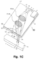
- FIG. 1A, 1B, 1C and 1D Sketches and cross-sectional views of preferred embodiments of time-of-flight velocimeters according to the invention are shown in Figs. 1A, 1B, 1C and 1D.
- a laser beam 20 provided by a laser 10 is directed on to a diffractive optical transmitter and receiver element 80 having incorporated two transmitter diffracting structures 81,82 for splitting the beam 20 into two beams 21,22 and for focusing said two beams onto two non-intersecting closely spaced focal areas 71,72 on a moving object element 70.
- correlated detector signals 51,52 are generated and processed by signal processing means 60 comprising an electronic time-of-flight correlator 60 providing an output signal 61 proportional to the time-of- flight or the velocity of the object between the focal areas 71,72.
- Fig. 1C shows a preferred embodiment of the invention in form of an integrated opto-electronic element 90 comprising a substrate 91 and a waveguide 92 for distribution of light from a laser 10 to the transmitter diffracting structures 81,82 and for collection and distribution of light from the receiver diffracting structures 83,84 to the detectors 41,42, the light from said laser 10 being edge-coupled to the waveguide 92 and the detectors 41,42 being integrally incorporated in the waveguide 92.
- the dashed lines indicate the beam confinements of the respective beams, e.g. the laser beam 20 and the two transmitted beams 21 and 22.
- Fig. 1D shows a cross section, corresponding to line A-A' of Fig. 1C, of an embodiment of the invention, comprising in-coupling means 93 consisting of a diffracting structure incorporated in the waveguide 92 for surface coupling of light from the laser 10 to the waveguide 92, and comprising out-coupling means 94 consisting of a diffracting structure incorporated in the waveguide 92 for surface coupling of light from the waveguide 92 to the detectors 41 and 42.
- the signal processing means 60 consist of an integrated signal processor mounted on the substrate 91.
- Figs. 2A (top view) and 2B (cross-sectional view along the line IIB-IIB) show a diffractive optical element 80 comprising:
- the semiconductor laser 10 and detectors 41,42 are normal components in integrated optics, and the integrated signal processor 60 is an integrated electronic processor, e.g. a delay lock loop or an equivalent processor, electronically connected to the semiconductor detectors 41,42.
- the integrated signal processor 60 is an integrated electronic processor, e.g. a delay lock loop or an equivalent processor, electronically connected to the semiconductor detectors 41,42.
- the surface waveguide 92, and the diffracting structures 81,82, 83,84, and 93,94 can be realized using e.g. the methods disclosed by P.J. Cronkite and G.N. Lawrence in “Focusing Grading Coupler Design Methods Using Holographic Optical Elements", Applied Optics, Vol. 27, 1988, pp. 679- 683.
- the time-of-flight measurement according to the invention can be performed in basically three different operational modes as illustrated in Figs. 3A, 3B and 3C showing crosssectional top views of various sizes and relative positions of the apertures of the diffracting structures of the transmitter means 81 and the receiver means 83, respectively.
- Figs. 3A, 3B and 3C showing crosssectional top views of various sizes and relative positions of the apertures of the diffracting structures of the transmitter means 81 and the receiver means 83, respectively.
- Figs. 3A, 3B and 3C showing crosssectional top views of various sizes and relative positions of the apertures of the diffracting structures of the transmitter means 81 and the receiver means 83, respectively.
- Figs. 3A, 3B and 3C showing crosssectional top views of various sizes and relative positions of the apertures of the diffracting structures of the transmitter means 81 and the receiver means 83, respectively.
- the circumference of the diffractive optical element 80 is not shown either.
- the aperture of the diffracting structures of the transmitter means 81 has the same size and relative position as the aperture of the diffracting structures of the receiver means 83.
- the apertures of the diffracting structures are of the same size as the mean speckle size.
- the generated detector signals are dominated by the surface roughness and cross particle interference components, the detector signal bandwidth is determined by the reciprocal value of the transit time which it takes the object element to pass one beam, i.e. the beam diameter and the velocity of the object element, and the modulation of the detector signals may be close to unity.
- the aperture of the diffracting structures of the receiver means 83 is larger than the aperture of the diffracting structures of the transmitter means 81.
- the modulation of the generated detector signal caused by speckles (surface roughness) is decreased, and the amplitude modulation of the signal caused by variations in reflectivity or transmittivity provides a larger contribution to the detected signal than in the coherent detection mode.
- the detector signal is dominated by reflectivity or transmissivity variations, the bandwidth is determined by the spatial scale of reflectivity or transmissivity variations, single particle contributions, and the velocity of the object element, and the modulation of the detector signals is generally lower than unity.
- Fig. 3C shows another variant of the diffracting structure for the incoherent detection mode in which the diffracting structures of the transmitter means 81 are annually overlapped by the diffracting structures of the receiver means 83.
- the axes of the respective diffracting structures are orientated so that the direction of the transmitted radiation coincides with the direction of the received scattered or diffracted radiation.
- the effective aperture (as determined by the diameter of the reference beam) of the diffracting structures of the receiver 83 is identical to the aperture of the diffracting structures of the transmitter means 81 as in the coherent detection mode.
- the scattered light interferes with reference beams.
- the detector signals are dominated by surface roughness, reflectivity or transmissivity variations, and single particle interference, the detector signal bandwidth is determined by the beam diameter and the velocity of the object being measured, and the modulation of the detector signals comprises a large DC component caused by the reference beam.
- Reference beam detection mode may be applied if a parametric amplification of the signal is needed, because the detector signal has an amplitude proportional to the product of the reference field amplitude and the scattered or diffracted field amplitude in weak scattering or weak diffracting mode, i.e. in cases where the scattered or diffracted power is much smaller than the power of the directly transmitted beam.
- the time-of-flight measuring principle according to the invention can be implemented in a number of different configurations of the transmitter means (Figs. 4A-4C) and the receiver means (Figs. 5A-5C) which configurations can be combined for selected purposes.
- Fig. 4A shows a transmitter configuration of the transmitter means consisting of an electromagnetic radiation source 10 having a wavelength in the optical range and providing a beam of electromagnetic radiation, and a diffractive optical element 80 receiving and directing the electromagnetic radiation on to two spots 71,72 on the object 70.
- the diffractive optical element 80 comprises two partially overlapping diffracting structures which are displaced a distance corresponding to the distance between the two spots on the object.
- the two beams have substantially parallel optical axes.
- This configuration is preferred for most applications.
- Fig. 4B is similar to Fig. 4A with the exception that the two diffracting structures fully overlap and provide nonparallel optical axes of the two beams. This configuration is simpler and has a higher efficiency than the one shown in Fig. 4A because both beams have the same intensity, whereas the exact calibration depends on the distance to the object.
- Fig. 4C is similar to Fig. 4A with the exception that the functions of splitting up and focusing of the electromagnetic beam of the diffracting structures are divided into two separate diffractive optical elements 80A,80B. This configuration is particularly useful in cases where a large focal depth is to be combined with a larger beam separation.
- Fig. 5A shows a configuration of the receiver means consisting of an object 70 scattering or diffracting electromagnetic radiation from two spots 71,72.
- the light scattered or diffracted from the two spots 71,72 is collected by the diffractive optical element 80 and directed on to the detectors 41,42.
- the diffractive optical element 80 comprises two fully overlapping diffracting structures.
- Fig. 5B is similar to Fig. 5A with the exception that the two diffracting structures do not fully overlap.
- Fig. 5C is similar to Fig. 5B with the exception that the receiver receives forward scattered or diffracted light.
- any of the transmitter means configurations shown in Figs. 4A-4C may be combined with any of the receiver means configurations shown in Figs. 5A-5C.
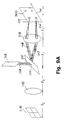
- Fig. 6A shows a preferred embodiment of the Doppler velocimeter apparatus according to the invention in form of an integrated opto-electronic element 100 that can be designed according to the same principles as the integrated opto-electronic elements 90 shown in Figs. 1C and 1D and thoroughly described in the previous paragraphs.
- the integrated opto-electronic element 100 comprises a substrate 101 and a waveguide 102 for distribution of light from a first laser 103 to a first transmitter diffracting structure 104, from a second laser 105 to a second transmitter diffracting structure 106, from a first relatively weakly diffracting diffracting structure 107 superposed on the transmitting diffracting structure 104 to a diffracting structure 108 situated in front of the photodetector 109, from a second relatively weakly diffracting diffracting structure 110 superposed on the transmitting diffracting structure 106 to the diffracting structure 108, which is matched to the angle between the two light beams emerging from the two relatively weakly diffracting structures 107, 110 so that the light beams can be coherently detected by the photodetector 109, and for collection and distribution of light from the receiver diffracting structure 111 to a light detector 112.
- the dashed lines indicate the beam confinements of the respective beams, e.g. the laser beam 113 and the two transmitted beams 114 and 115.
- the two light beams 114, 115 emerging from the transmitting diffracting structures 104, 106 cross each other at the measurement volume 116.
- a fringe pattern is created in the measurement volume 116 defined by the crossing beams 114, 115.
- an object passes through the measurement volume, it scatters, reflects, refracts or diffracts light of fluctuating intensity as it passes alternating fringes with a high intensity of light and fringes with a very low light intensity.
- the frequency of the light intensity fluctuations is proportional to the velocity of the object in the direction perpendicular to the fringes and it is inversely proportional to the wavelength of the light beam.
- the frequency of the light fluctuations does not contain information of the direction of the movement of the object.
- the frequency of one of the light beams 115 is shifted slightly with respect to the frequency of the other light beam 114, the fringe pattern will move across the measurement volume at a rate corresponding to the frequency shift.
- a moving fringe pattern it is possible to determine the direction of the movement of an object as a movement in the opposite direction of the movement of the fringes adds to the frequency shift while a movement in the same direction as the fringe movement subtracts from the frequency shift.
- the frequency shift is provided by providing the light beams 114, 115 by two separate lasers 103, 105 the frequency difference between which is locked to a preset value defining the frequency shift.
- the locking of the frequency difference between the two separate lasers 103, 105 comprises optical mixing of light beams 117, 118 from the two lasers on a photodetector 109.
- the light beams 117, 118 are diffracted by relatively weakly diffracting diffracting structures 107, 110 superposed on the transmitting diffracting structures 104, 106 and they are combined by a diffracting structures 108 situated in front of the photodetector 109, the diffracting structure 108 being matched to the angle between the two light beams 117, 118 emerging from the two relatively weakly diffracting structures 107, 110 so that the light beams can be coherently detected by the photodetector 109.
- the electrical signal from the photodetector 109 is fed to a phase-locked loop 119 that generates a control signal for the laser 105 to control the frequency of the light beam 115.
- the two diffracting regions 104, 106 are laterally displaced relative to each other and designed so that the angle between the intersecting beams 114, 115 radiated by the diffracting regions 104, 106 depends on the wavelength in such a way that the resulting calibration of the method is substantially independent of the wavelength of the light sources 103, 105.
- the light emerging from an object passing through the measurement volume 116 is collected by a receiving diffracting structure 111 that couples the received light into the waveguide 102 for transmission of the received light to the light detector 112.
- the signal processing means 120 consist of an integrated signal processor mounted on the substrate 100.
- Fig. 6B shows parts of another embodiment of a Doppler velocimeter according to the invention, wherein a semiconductor laser 140 generates a light beam 141 that is transmitted to a Bragg cell 142.
- the Bragg cell 142 splits the beam 141 into two beams 143, 144 where one beam 144 is frequency shifted relatively to the other beam 143.
- the two beams 143, 144 are diffracted by two diffracting structures 145, 146 whereby the crossing beams 147, 148 are generated.
- Light emerging from an object passing the measurement volume 149 is collected by a receiving diffracting structure 150 that collects and directs the received light to the light detector 151.
- Fig. 7 shows a preferred embodiment of the viscoelastic determination apparatus according to the invention in form of an integrated opto-electronic element 200 that can be designed according to the same principles as the integrated opto-electronic elements 90 shown in Figs. 1C and 1D and thoroughly described in the corresponding paragraphs.
- the integrated opto-electronic element 200 comprises a substrate 201 and a waveguide 202 for distribution of light from a laser 203 to a first transmitter diffracting structure 204 and to a second transmitter diffracting structure 205, and for collection and distribution of light from the receiver diffracting structure 206 to a light detector 207.
- the dashed lines indicate the beam confinements of the respective beams, e.g. the two transmitted beams 208, 209.
- the light beam from the laser 203 are splitted into two beams 211, 212 by a beam splitter (not shown), such as a diffracting structure an optical waveguide beam splitter, etc.
- the two light beams 208, 209 emerging from the transmitting diffracting structures 204, 205 are of different light intensities and cross each other at the gas/liquid interface 210.
- the capillary waves on the gas/liquid interface 210 diffract and reflect light incident on the gas/liquid interface 210.
- a receiver means comprising a third diffracting structure 206 collects light emerging from the intersecting area on the gas/liquid interface 210.
- the collected light comprises reflected light from the light beam 208 of weak light intensity and a diffracted light from the capillary waves on the gas/liquid interface of the light beam of strong light intensity. Furthermore, the receiving diffracting structure 206 transmits the collected light to a light detector 207 in such a way that optical heterodyning is achieved on the light detector 207 which convert the light to electrical signals. It has already been proven that the frequency differences of the reflected and the diffracted light contain information about the presence and propagation of capillary waves on the gas/liquid surface 210. It has been shown that the mean of the frequencies indicates the viscosity of the liquid while the standard deviation indicates the surface tension of the liquid.
- the signal processing means of the viscoelastic determination apparatus comprise a phase lock demodulator 213 for the processing of the detector 207 signal, the output of the phase lock loop 213 being fed to a low pass filter 214 and a band pass filter 215, respectively, the outputs from the two filters providing the inputs for a look-up table integrated circuit 216 designed in such as a way that the outputs of the look-up table directly give the viscosity and the surface tension.
- Fig. 8 shows a preferred embodiment of the differential electronic speckle apparatus according to the invention used to determine differential displacement or vibration pattern of a surface of an object.
- Light is transmitted to the object 250 from a light source 251 through a beam expander 252.
- Light that has interacted with the object 250 is collected by a light collecting system 253 with two diffracting structures 254, 255 that, in combination with a lens 256, generate two different images on a detector array 257.
- the two diffracting structures 254, 255 consist essentially of diffracting structures of slightly different spatial frequencies, whereby two displaced images are generated in the detector array 257.
- the mode of operation of the apparatus can be understood by imagining that an image of a grating is created on the surface of the object. Then, two mutually displaced images of the object are provided on the detector 257. By relative displacements or vibrations of the object 250 interference of the two mutually displaced images will create moire-like patterns on the detector 256 indicating the magnitude and location of the relative displacement or vibration.
- a diffracting structure and a zone-plate lens can be superposed, whereby a sharp and a smeared image are obtained on the detector array 256.
- Figs. 9A and 9B show a preferred embodiment of the differential vibrometer according to the invention used to determine time-resolved relative displacements on a surface of an object.
- the principle mode of operation of this method and apparatus corresponds to the mode of operation of the differential electronic speckle apparatus described above, but the present method measures on a set of spots 300 on the surface of the object 301 and not on an area of the object 301.
- a laser 302 generates a light beam 303 incident on a diffractive optical element 304 comprising a set of superposed diffracting structures 305 for splitting the laser beam 303 into at least two angularly separated beams 306, 307.
- a Fourier-transforming lens 308 focuses the at least two beams 306, 307 in at least two spots 309, 310 on the surface of the object 301.
- Light that has interacted with the surface of the object is collected by the Fourier-transforming lens 308 and transmitted to an annular diffracting region 313 of the diffractive optical element 304 where another set of diffracting structures 314 is superposed which, in combination with a lens 315, causes light from pairs of spots to be combined on the detector elements 316.
- the diffracting structures 305 are designed so that when combined with the Fourier transforming lens 308 the resulting calibration of the method is substantially independent of the wavelength of the light source 302.
- Fig. 10 shows a preferred embodiment of the distance determination apparatus according to the invention.
- a laser 353 generates a light beam transmitted to a diffracting structure 354 that transmits a light beam 359, preferably a collimated light beam, to the surface 357 of the object.
- Light 360 reflected from the surface 357 of the object is collected by a chirped diffracting structure 355 and transmitted to a detector array 356 so that light 360 reflected from a surface 357 at a specific distance from the diffractive optical element 350 is directed to a detector 358 corresponding to that distance.
- the diffracting structures 354, 355 are designed so that the changes of the angle of the light beam 359 emerging from the transmitting diffracting structure 354 as a function of the wavelength of the light source 353 corresponds to the focusing by the chirped diffracting structure 355 as a function of the angle of the light beam 360 incident on the chirped diffracting structure pattern 355 in such a way that the determination of distance is independent of the wavelength of the light source 353.
- Monolithic holographic optical elements can be prepared by methods known in the art.
- Diameter of the aperture 7 mm Distance between the two spots on the object 700 microns Diffraction angle of transmitter beam relative to the normal of the hologram 9° Focusing distance to the object 117 mm Spot size on the object 70 microns
- All the focal lengths refer to a wavelength of 820 nm.
- the monolithic holographic optical element is demonstrated by the preparation of a so-called volume phase hologram for which it is possible to store multiple diffracting structures superimposed with negligible cross-talk by angular multiplexing. Also, the volume phase hologram facilitates the recording of diffractive optical elements with a diffraction efficiency approaching 100%.
- Figs. 11A and 11B for exposure of the recording material is based on the Leigh & Upatnieks off axis geometry, cf. R.R.A. Syms, "Practical Volume Holography", p. 119, Clarendon Press Oxford, 1990, which facilitates the separation of the readout beam and the diffracted beam.
- the holographic optical element 610 comprises a substrate 611, e.g. an AGFA 8 E 75 glass plate, having a layer of photosensitive material 612, e.g. dichromated gelatin, said substrate being placed on an absorbing layer 613, e.g. a Schott filter RG 630 index matched to the substrate by an immersion oil for reducing the formation of spurious diffracting structures caused by the Fresnel reflections from the rear side of the substrate.
- a substrate 611 e.g. an AGFA 8 E 75 glass plate
- a layer of photosensitive material 612 e.g. dichromated gelatin
- an absorbing layer 613 e.g. a Schott filter RG 630 index matched to the substrate by an immersion oil for reducing the formation of spurious diffracting structures caused by the Fresnel reflections from the rear side of the substrate.
- Fig. 11A shows the exposure configuration for recording the transmitter diffracting structures comprising the object beam 614 and the reference beam 615 both having an angle ⁇ to the normal of the substrate.
- the symmetrical reference and object beams are used to create an unslanting diffracting structure, i.e. a fringe pattern perpendicular to the film surface.
- This type of diffracting structure significantly reduces the effects of swelling or shrinkage of the holographic film due to the chemical processing.
- the direction of the translation of the substrate between exposures is indicated by the arrow the distance of translation being the distance between the two spots on the object, e.g. 700 microns.
- Gaussian beams were used in the exposure.
- the exposure geometry of the receiver diffracting structure is shown in Fig. 11B.
- the angle ⁇ between the reference beam and the normal to the substrate was 3,3°. It was found, experimentally, that if the substrate was tilted 10° clockwise prior to exposure, a considerable reduction in aberrations of the receiver hologram could be achieved.
- Fig. 11C the layout of the processed hologram can be seen for a substrate of 50 mm in diameter showing a transmitter hologram 618 comprising the two overlapping diffracting structures for providing the two spots on the object and a receiver hologram 619 for receiving and directing the collected, scattered or diffracted light onto the detector means.
- the angle ⁇ between the reference beam and the normal to the substrate was 5,3°.
- the aperture of the exposed region was 4 mm in diameter.
- the calibration of the sensor was determined by the offset between the two transmitting holograms. This offset was achieved by a translation of the substrate between the exposures. In this embodiment the substrate was translated 700 microns.
- a dichromated gelatin film was prepared as follows: 2.00 g of gelatin (Bloom Strength 250, Fluka Lot No. 48724) was added to 100 ml of deionised water and allowed to swell for 15 minutes at room temperature (20-25°C) under continuous stirring with a magnetic stirrer.
- the gelatin-water suspension was heated to 50°C and the gelatin allowed to dissolve.
- the solution was kept at a temperature of 50°C for 5 minutes under continuous stirring.
- the dichromated gelatin solution was filtered through a 0.5 ⁇ m pore size filter (MillexTM, Millipore).
- the filtered dichromated gelatin solution was allowed to cool to 30-35°C and then using a precision pipette of 2 ml fixed volume applied to a glass plate (50 mm diameter gravity settling plate) cleaned and maintained at 10°C
- the applied dichromated gelatin solution was allowed to gel at 10°C for 15 minutes, the temperature of the plate was increased to 14-15°C, and the dichromated gelatin film was allowed to dry for 12 hours.
- a thickness of 20 tim dry pre-exposed dichromated gelatin film was obtained.
- the prepared dichromated gelatin film was sequentially exposed by applying the above-mentioned interferometric exposure techniques and parameter specifications of the transmitter and receiver holograms.
- the dichromated gelatin film was developed through a series of chemical processing steps at an ambient relative humidity of 40-50%.
- the film was immersed in a fixer containing 25 ml hardener (Aditan) per 1000 ml fixer solution (AGFA G-350), and agitated continuously for 3 minutes at a temperature of 20-25°C bulk hardening of the gelatin and converting unreacted Cr +6 ions to Cr +3 ions (as observed by a purple colouring of the solution due to Cr[H 2 O] +3 ions).
- Aditan hardener
- AGFA G-350 1000 ml fixer solution
- the film was rinsed in running water for 5 minutes at a temperature of 35°C. Unreacted fixing agent and Cr +3 ions were removed and the hardened gelatin film was allowed to swell.
- the swollen gelatin film was dehydrated for 3 minutes in a 50% mixture of water and 2-propanol at a temperature of 20-25°C, and 3 minutes in a 100 * 2-propanol at a temperature of 20-25°C, thereby fixing the refractive index modulation of the phase diffracting structure Residual water was removed under vacuum.
- the developed dichromated gelatin film was conditioned in a desiccator for 24 hours removing traces of water.
- the final film thickness of the dichromated gelatin film was 50 tim.
- a cover glass was applied to the surface of the conditioned, developed dichromated gelatin film using an epoxy glue, e.g. EpotekTM 301, or an UV-curable glue, e.g. NorlandTM 61, under conditions of low humidity, e.g. less than 30% relative humidity, or protective inert atmosphere N 2 or Ar.
- an epoxy glue e.g. EpotekTM 301
- an UV-curable glue e.g. NorlandTM 61
- a time-of-flight surface velocimeter according to the invention consisting of:
- a sandpaper having a particle size of 40 tim was mounted on a rotary disc in a position providing a tangential velocity of 3.3 m/s.
- a cross-correlation of the measured detector signals was provided showing a maximum cross correlation at 211 ⁇ s corresponding to a measure velocity of 3.32 m/s for a distance between the spots of 700 tim.
Claims (116)
- Verfahren zum Bestimmen einer Bedingung bzw. eines Zustandes eines Objektes (70, 250, 301, 357) auf der Grundlage quasi-elastischer Wechselwirkung zwischen dem Objekt (70, 250, 301, 357) und Licht (21, 22, 114, 115, 147, 148, 208, 209, 306, 307, 359), das zu dem Objekt (70, 250, 301, 357) übertragen wird, das die Übertragung des Lichtes zu dem Objekt (70, 250, 301, 357) von einer Lichtquelle (10, 103, 105, 140, 203, 251, 302, 353) über wenigstens ein beugendes optisches Element (80, 258, 304) und das Auffangen sowie Erfassen von Licht (23, 24, 254, 255, 360), das in Wechselwirkung mit dem Objekt (70, 250, 301, 357) getreten ist, umfaßt, wobei das wenigstens eine optische Beugungselement (80, 304, 258) wenigstens einen beugenden Bereich enthält, das wenigstens eine optische Beugungselement (80, 258, 304) sowohl das funktionelle Prinzip des Verfahrens als auch die Kalibrierung des Verfahrens definiert und zwar so, daß sowohl das funktionelle Prinzip als auch die Kalibrierung im wesentlichen ausschließlich durch das wenigstens eine optische Beugungselement (80, 258, 304) definiert werden,
dadurch gekennzeichnet, daß:
der beugende Bereich wenigstens zwei beugende Strukturen (81, 82) umfaßt, die zueinander seitlich versetzt und so ausgelegt sind, daß die Achsen der übertragenen Strahlen (21, 22), die von den wenigstens zwei beugenden Strukturen (81, 82) ausgestrahlt werden, jeweils im wesentlichen parallel sind und der Abstand zwischen den Achsen im wesentlichen unabhängig von der Wellenlänge der Lichtquelle (10, 103, 105, 140, 203, 251, 302, 353) ist,
und/oder, daß
der Winkel zwischen einander schneidenden Strahlen (114, 115, 147, 148, 208, 209, 306, 307, 359, 360), die von wenigstens einem beugenden Bereich (104, 106, 145, 146, 204, 205, 305, 354) ausgestrahlt werden, von der Wellenlänge abhängt, und zwar so, daß die resultierende Kalibrierung des Verfahrens im wesentlichen unabhängig von der Wellenlänge der Lichtquelle (103, 105, 140, 203, 302, 353) ist, so daß das Bestimmen im wesentlichen unabhängig von den Eigenschaften der Lichtquelle ist. - Verfahren nach Anspruch 1, wobei die Bedingung bzw. der Zustand eine dynamische Bedingung bzw. ein dynamischer Zustand ist.
- Verfahren nach Anspruch 1 oder 2, wobei das optische Beugungselement (80, 258, 304) mehr als einen beugenden Bereich umfaßt, der wenigstens eine beugende Struktur (81, 82, 83, 84, 104, 106, 111, 145, 146, 150, 204, 205, 206, 254, 255, 305, 314, 354, 355) umfaßt.
- Verfahren nach einem der Ansprüche 1-3, wobei die wenigstens zwei zueinander seitlich versetzten beugenden Strukturen (81, 82, 104, 106, 145, 146, 204, 205) einander teilweise überlappen.
- Verfahren nach Anspruch 4, wobei die Flächen, die von den wenigstens zwei zueinander seitlich versetzten beugenden Strukturen (81, 82, 104, 106, 145, 146, 204, 205) eingenommen werden, im wesentlichen die gleiche Größe und Form haben und/oder die beugenden Strukturen (81, 82, 104, 106, 145, 146, 204, 205) im wesentlichen identisch sind.
- Verfahren nach Anspruch 4 oder 5, wobei die Überlappung der wenigstens zwei zueinander seitlich versetzten beugenden Strukturen (81, 82, 104, 106, 145, 146, 204, 205) so bestimmt wird, daß die im wesentlichen bestmögliche Nutzung des Raum-Bandbreiten-Produktes gewährleistet ist.
- Verfahren nach einem der Ansprüche 1-3, wobei die beugenden Bereiche (104, 106, 145, 146, 204, 205), die einander schneidende Strahlen ausstrahlen, um einen Abstand zueinander versetzt sind, der im wesentlichen größer ist als eine charakteristische Größe der einzelnen beugenden Bereiche (104, 106, 145, 146, 204, 205).
- Verfahren nach einem der vorangehenden Ansprüche, wobei Licht (23, 24, 254, 255, 360), das in Wechselwirkung mit dem Objekt (70, 250, 301, 357) getreten ist, mittels eines beugenden Bereiches (83, 84, 111, 150, 206, 254, 255, 314, 355) aufgefangen und auf wenigstens einem Lichtdetektor (41, 42, 112, 151, 207, 257, 316, 356, 358) abgebildet wird.
- Verfahren nach Anspruch 8, wobei die Fläche jeder der beugenden Strukturen (83, 84, 111, 150, 206, 314, 355), mittels derer Licht, das mit dem Objekt (70, 250, 301, 357) in Wechselwirkung getreten ist, aufgefangen und auf wenigstens einem Lichtdetektor (41, 42, 112, 151, 207, 257, 316, 356, 358) abgebildet wird, im wesentlichen identisch mit der Fläche einer der beugenden Strukturen (81, 82, 104, 106, 145, 146, 204, 205, 305, 354) ist, durch die das Licht (21, 22, 114, 115, 147, 148, 208, 209, 306, 307, 359), das zu dem Objekt (70, 250, 301, 357) übertragen wurde, hindurchgetreten ist, wenn ein vollständig entwickeltes Tupfenmuster auftritt.
- Vefahren nach Anspruch 8, wobei die Fläche jeder der beugenden Strukturen (83, 84, 111, 150, 206), mittels derer Licht, das mit dem Objekt (70, 250, 301, 357) in Wechselwirkung getreten ist, aufgefangen und auf wenigstens einem Lichtdetektor (41, 42, 112, 151, 207, 257, 316, 356, 358) abgebildet wird, größer ist als die Fläche einer der beugenden Strukturen (81, 82, 104, 106, 145, 146, 204, 205, 305, 354), durch die das Licht (21, 22, 114, 115, 147, 148, 208, 209, 306, 307, 359) das zu dem Objekt (70, 250, 301, 357) übertragen wurde, hindurchgetreten ist, wenn ein vollständig entwickeltes Tupfenmuster auftritt.
- Verfahren nach einem der Ansprüche 8-10, wobei der beugende Bereich (83, 84, 111, 150, 206, 314, 355), mittels dessen Licht, das mit dem Objekt (70, 250, 301, 357), in Wechselwirkung getreten ist, aufgefangen und auf wenigstens einem Lichtdetektor (41, 42, 112, 151, 207, 257, 316, 356, 358) abgebildet wird, sich auf dem gleichen optischen Beugungselement (80, 258, 258, 304) befindet wie der wenigstens eine beugende Bereich (81, 82, 104, 106, 145, 146, 204, 205, 305, 354), durch den das Licht (21, 22, 114, 115, 208, 209), das zu dem Objekt (70, 250, 301, 357) übertragen wurde, hindurchgetreten ist.
- Verfahren nach einem der vorangehenden Ansprüche, wobei die optischen Beugungselemente (80, 258, 304) Beugungslinsen umfassen, die aus der Gruppe holographischer optischer Elemente, wie beispielsweise der Elemente ausgewählt werden, die interferometrisch erzeugte Hologramme, computererzeugte Hologramme einschließlich Kinoformen, elektronenstrahlgeschriebene Hologramme, Randausleuchtungshologramme, wellenleitergekoppelte Hologramme, Tiefen-Oberflächenrelief-Hologramme, mikrobearbeitete Hologramme und Fresnel-Zonen-Platten umfassen.
- Verfahren nach einem der vorangehenden Ansprüche, wobei das eine bzw. die mehreren optischen Beugungselemente (80, 258, 304) eine monolithische Struktur (90, 100, 200) umfassen, die umfaßt; ein geeignetes, mechanisch stabiles Substrat (91, 101, 201) und eine Schicht aus optischem Aufzeichnungsmaterial, auf die beugende Strukturen (81, 82, 83, 84, 104, 106, 111, 145, 146, 150, 204, 205, 206, 254, 255, 305, 314, 354, 355), aufgezeichnet sind.
- Verfahren nach einem der vorangehenden Ansprüche, wobei das eine oder die mehreren optischen Beugungselemente (80, 258, 304, 350, 610) in ein integriertes optoelektronisches Element (90, 100, 200) eingebaut sind.
- Verfahren nach Anspruch 14, wobei das integrierte optoelektronische Element (90, 100, 200) ein Substrat (91, 101, 201) und einen Wellenleiter (92, 102, 202) umfaßt, der die geeigneten beugenden Strukturen (81, 82, 83, 84, 104, 106, 111, 145, 146, 150, 204, 205, 206, 254, 255, 305, 314, 354, 355) umfaßt, die in diesen bzw. in die Grenzfläche zwischen dem Wellenleiter (92, 102, 202) und dem Substrat (91, 101, 201) integriert sind.
- Verfahren nach Anspruch 15, wobei der Wellenleiter (92, 102, 202) eine Einheit mit dem Substrat (91, 101, 201) bildet.
- Verfahren nach einem der Ansprüche 14-16, wobei das integrierte optoelektronische Element (90, 100, 200) eine Einkopplungseinrichtung (92) zum Einkoppeln von Licht von der Lichtquelle (40, 103, 105, 140, 203, 251, 302, 353) in den Wellenleiter (92, 102, 202) hinein umfaßt.
- Verfahren nach einem der Ansprüche 14-17, wobei das integrierte optoelektronische Element (90, 100, 200) eine Auskopplungseinrichtung (94) zum Auskoppeln des aufgefangenen, gestreuten bzw. gebeugten Lichtes (23, 24, 254, 255, 360) aus dem Wellenleiter (92, 102, 202) heraus umfaßt.
- Verfahren nach den Ansprüchen 17 oder 18, wobei die Einkopplungseinrichtung (92) und die Auskopplungseinrichtung (94) bzw. beide aus Kopplungsvorrichtungen bestehen, die aus der Gruppe ausgewählt sind, die aus einer beugenden Struktur (93, 94), die in den Wellenleiter (92, 102, 202) oder in die Grenzfläche zwischen dem Wellenleiter (92, 102, 202) und dem Substrat (91, 101, 201) integriert ist, einem Prisma, oder einer Stirnflächenkopplung besteht.
- Verfahren nach den Ansprüchen 14-19, wobei die Strahlerzeugungseinrichtung, die Detektoreinrichtung oder beide extern mit dem integrierten optoelektronischen Element (90, 100, 200) verbunden sind.
- Verfahren nach den Ansprüchen 14-19, wobei die Strahlerzeugungseinrichtung, die Detektoreinrichtung oder beide in das integrierte optoelektronische Element (90, 100, 200) eingebettet sind.
- Verfahren nach einem der Ansprüche 14-21, wobei die Signalverarbeitungseinrichtungen (60, 120, 213) einen integrierten Signalprozessor umfassen, der in das integrierte optoelektronische Element (90, 100, 200) eingebaut werden kann.
- Verfahren nach einem der vorangehenden Ansprüche, wobei die Detektoreinrichtungen (41, 42, 112, 151, 207, 257, 356, 358) wenigstens einen Halbleiter-Detektor umfassen.
- Verfahren nach einem der vorangehenden Ansprüche, wobei die Lichtquelle (10, 103, 105, 140, 203, 251, 302, 353) ein Laser ist.
- Verfahren nach Anspruch 24, wobei die Lichtquelle (10, 103, 105, 140, 203, 251, 302, 353) ein Halbleiterlaser ist.
- Verfahren nach einem der Ansprüche 1-23, wobei die Lichtquelle (10, 103, 105, 140, 203, 251, 302, 353) eine Superlumineszenzdiode ist.
- Verfahren nach einem der vorangehenden Ansprüche, wobei die Wellenlänge des Lichtes im Bereich von UV-Strahlung bis zu Funkwellen im Radarbereich, insbesondere im Bereich von ungefähr 400 nm bis 1600 nm, vorzugsweise ungefähr 600 nm bis 900 nm, liegt.
- Verfahren nach einem der vorangehenden Ansprüche, wobei es sich bei dem Bestimmen um das Bestimmen der Geschwindigkeit bzw. eines von der Geschwindigkeit abgeleiteten Parameters eines sich bewegenden Objektes (70) unter Verwendung des Laufzeitverfahrens handelt.
- Verfahren nach Anspruch 28, wobei das beugende Aufspalten und Leiten des Lichtes auf zwei räumlich getrennte Bereiche (71, 72) des Objektes (70) durch zwei einander teilweise überlappende beugende Strukturen (81, 82) ausgeführt wird, die zueinander seitlich um einen Abstand versetzt sind, der im wesentlichen identisch mit dem Zwischenraum zwischen den zwei räumlich getrennten Bereichen (71, 72) des Objektes (70) ist, und die so ausgelegt sind, daß die Achsen der übertragenen Strahlen (21, 22), die von den wenigstens zwei beugenden Strukturen (81, 82) ausgestrahlt werden, jeweils im wesentlichen parallel zueinander sind und der Abstand zwischen den Achsen im wesentlichen unabhängig von der Wellenlänge der Lichtquelle (10) ist.
- Verfahren nach Anspruch 28 oder 29, wobei Licht, das mit dem Objekt (70) in Wechselwirkung getreten ist, mittels zweier, einander vollständig oder teilweise überlappender beugender Strukturen (83, 84) aufgefangen und auf wenigstens einem Lichtdetektor (41, 42) abgebildet ist.
- Verfahren nach einem der Ansprüche 28-30, wobei die Beugungselemente (80) der Übertragungseinrichtung zwei einander überlappende beugende Strukturen (81, 82), deren Versetzung zueinander kürzer ist als der Zwischenraum zwischen den zwei räumlich getrennten Bereichen (71, 72) auf dem Objekt (70), vorzugsweise zwei einander vollständig überlappende beugende Strukturen (81, 82), umfassen, die im wesentlichen nichtparallele Achsen der beiden Strahlen (21, 22) erzeugen.
- Verfahren nach einem der Ansprüche 28-31, wobei die zwei einander teilweise überlappenden beugenden Strukturen der Empfangseinrichtung und der Übertragungseinrichtung jeweils die gleiche relative Position und die gleichen Öffnungen haben wie die beugenden Strukturen (81, 82) der Übertragungseinrichtung.
- Verfahren nach einem der Ansprüche 28-32, wobei die Öffnungen der beugenden Strukturen (83, 84) der Empfangseinrichtung größer sind als die Öffnungen der beugenden Strukturen (81, 82) der Übertragungseinrichtung.
- Verfahren nach einem der Ansprüche 1-27, wobei es sich bei dem Bestimmen um das Bestimmen der Geschwindigkeit eines Objektes (70, 250, 301, 357) unter Verwendung des differentiellen Doppler-Geschwindigkeits-Verfahrens handelt.
- Verfahren nach Anspruch 34, wobei es sich bei dem Bestimmen um das Bestimmen einer Geschwindigkeitskomponente eines Objektes (70, 250, 301, 357) handelt.
- Verfahren nach Anspruch 35, wobei das Licht zu den zwei übertragenden beugenden Strukturen (104, 106, 145, 146, 204, 205) durch zwei separate Laser (103, 105) erzeugt wird, deren Frequenzdifferenz auf einem voreingestellten Wert gehalten wird.
- Verfahren nach Anspruch 36, wobei das Halten der Frequenzdifferenz zwischen den zwei separaten Lasern (103, 105) das optische Mischen von Lichtstrahlen von den zwei Lasern auf einem Photodetektor (109) umfaßt.
- Verfahren nach Anspruch 37, wobei eine beugende Struktur (107, 110) mit relativ schwacher Beugung über jeder der übertragenden beugenden Strukturen (104, 106) angeordnet ist, um einen Lichtstrahl von dem entsprechenden Laser (103, 105) zu einer beugenden Struktur (108) zu übertragen, die sich vor dem Photodetektor (109) befindet und an den Winkel zwischen den zwei Lichtstrahlen (117, 118) angepaßt ist, die aus den zwei relativ schwach beugenden Strukturen (107, 110) austreten, so daß die Lichtstrahlen (117, 118) von dem Photodetektor (109) kohärent erfaßt werden können.
- Verfahren nach Anspruch 35, wobei ein Laser (140, 203) eingesetzt wird.
- Verfahren nach Anspruch 35, wobei ein Laser (140) eingesetzt wird, und die Frequenzverschiebung mittels einer integrierten akustooptischen Struktur (142) erzielt wird.
- Verfahren nach Anspruch 40, wobei die integrierte akustooptische Struktur eine Bragg'sche Zelle (142) ist.
- Verfahren nach einem der Ansprüche 34-41, wobei es sich bei dem Bestimmen um ein Mehrkomponenten-Bestimmen der Geschwindigkeit eines Objektes (70, 250, 301, 357) handelt, das wiederholtes Duplizieren des Einkomponenten-Geschwindigkeitsbestimmens der Ansprüche 35-41 umfaßt.
- Verfahren nach einem der Ansprüche 1-27, wobei es sich bei dem Bestimmen um ein Bestimmen der Dynamik von Kapillarwellen an einer Gas-/Flüssigkeits-Grenzfläche auf der Grundlage dynamischer Lichtstreuung handelt.
- Verfahren nach Anspruch 43, wobei eine mittig angeordnete beugende Struktur (204) einen ersten Lichtstrahl (208) mit einem relativ großen Anteil der Lichtenergie von der Lichtquelle (203) auf die Oberfläche der Gas-/Flüssigkeits-Grenzfläche (210) zu überträgt, und ein zweiter beugender Bereich (205), der zu der ersten beugenden Struktur (204) versetzt ist, einen zweiten Lichtstrahl (209) mit einem relativ kleinen Anteil der Lichtenergie von der Lichtquelle (203) auf die Oberfläche der Gas-/Flüssigkeits-Grenzfläche (210) zu überträgt, und zwar so, daß der erste Lichtstrahl (208) den zweiten Lichtstrahl (209) an der Gas-/Flüssigkeits-Grenzfläche schneidet, und eine dritte beugende Struktur (206) das Licht auffängt, das aus dem Schnittpunkt aus der Gas-/Flüssigkeits-Grenzfläche (210) austritt, wobei das Licht eine Reflexion des zweiten Lichtstrahls (209) und eine Beugung des ersten Lichtstrahls (208) durch die Kapillarwellen an der Gas-/Flüssigkeits-Grenzfläche (210) umfaßt, und zwar so, daß optische Überlagerung auf dem Lichtdetektor (207) erreicht wird, auf den das aufgefangene Licht gerichtet wird.
- Verfahren nach Anspruch 43 oder 44, wobei ein Phasenverriegelungs-Demodulator (213) eingesetzt wird, um das Signal des Detektors (207) zu verarbeiten, wobei der Ausgang des Phasenverriegelungkreises (213) jeweils einem Tiefpaßfilter (214) und einem Bandpaßfilter (215) zugeführt wird, und die Ausgänge der zwei Filter (214, 215) die Eingänge für eine Verweistabelle (216) bilden, die so ausgelegt ist, daß der Ausgang der Verweistabelle (216) direkt die Viskosität und die Oberflächenspannung angibt.
- Verfahren nach einem der Ansprüche 1-27, wobei es sich bei dem Bestimmen um ein Bestimmen der Verschiebung bzw. des Schwingungsmusters einer Oberfläche eines Objektes (250) handelt.
- Verfahren nach Anspruch 46, das das Übertragen von Licht zu dem Objekt (250) von einer Lichtquelle (251) und das Auffangen von Licht, das mit dem Objekt (250) in Wechselwirkung getreten ist, über ein Lichtauffangsystem (253) umfaßt, das zwei beugende Strukturen (254, 255) enthält, die zwei verschiedene Bilder auf einer Detektoranordnung (257) erzeugen, wobei die Muster zusammen mit einer Linse (256) sowohl das funktionelle Prinzip des Verfahrens als auch die Kalibrierung des Verfahrens definieren, und zwar so, daß sowohl das funktionelle Prinzip als auch die Kalibrierung im wesentlichen ausschließlich durch die beugenden Strukturen (254, 255) und die Linse (256) und im wesentlichen unabhängig von den Eigenschaften der Lichtquelle (251) definiert werden.
- Verfahren nach Anspruch 47, wobei die zwei beugenden Strukturen (254, 255) im wesentlichen aus beugenden Strukturen mit geringfügig verschiedenen räumlichen Frequenzen bestehen, so daß zwei zueinander versetzte Bilder entstehen.
- Verfahren nach Anspruch 48, wobei eine beugende Struktur und eine Zonenlinse übereinander angeordnet sind, so daß ein scharfes und ein unscharfes Bild entstehen.
- Verfahren nach einem der Ansprüche 1-27, wobei es sich bei dem Bestimmen um ein Bestimmen zeitaufgelöster relativer Verschiebungen auf einer Oberfläche eines Objektes (301) handelt.
- Verfahren nach Anspruch 50, das den Einsatz einer Gruppe übereinander angeordneter beugender Strukturen (305) und einer Fourier-Transfomations-Linse (308) umfaßt, so daß eine Gruppe (305) von Punkten (309, 310) auf der Oberfläche erzeugt wird, das Licht, das mit der Oberfläche in Wechselwirkung getreten ist, von der gleichen Fourier-Transformations-Linse (308) aufgefangen wird und einen ringförmigen Teil (313) des Beugungselementes (304) passiert, in dem eine weitere Gruppe beugender Strukturen (314) übereinander angeordnet ist, so daß das Licht von den Paaren von Punkten (309, 310) auf den Detektorelementen (316) kombiniert wird, wobei die beugenden Strukturen (305, 314) zusammen mit einer Linse sowohl das funktionelle Prinzip des Verfahrens als auch die Kalibrierung des Verfahrens definieren, und zwar so, daß sowohl das funktionelle Prinzip als auch die Kalibrierung im wesentlichen ausschließlich durch die beugenden Strukturen (305, 314) und die Linse (308) und im wesentlichen unabhängig von den Eigenschaften der Lichtquelle (10, 103, 105, 251, 302, 353) definiert werden.
- Verfahren nach einem der Ansprüche 1-27, wobei es sich bei dem Bestimmen um das Bestimmen des Abstandes zu einem Objekt (357) durch Triangulation handelt.
- Verfahren nach Anspruch 52, das das Ausführen des Bestimmens mittels beugender Strukturen umfaßt, die zusammen mit einer eingebetteten Lichtquelle (353) und einer eingebetteten Detektoranordnung (358) in ein monolithisches planares Element (351) eingebaut sind, wobei das Koppeln von Licht von der Lichtquelle (353) zu einer übertragenden beugenden Struktur (354) durch einen eingebetteten Wellenleiter (352) ermöglicht wird, und das Koppeln von einer empfangenden beugenden Struktur (355) zu der Detektoranordnung (358) durch eine Gruppe eingebetteter Wellenleiter (352) ermöglicht wird.
- Verfahren nach Anspruch 53, wobei die übertragende beugende Struktur (354) einen kollimierten Strahl (359) erzeugt und die empfangende beugende Struktur (355) in bezug auf die Position der übertragenden beugenden Struktur (354) versetzt ist, die eine beugende Chirp-Struktur (355) enthält, so daß Licht (360), das von einer Oberfläche (357) in einem bestimmten Abstand zu dem optischen Beugungselement (351) reflektiert wird, zu einem Detektor (356) geleitet wird, der diesem Abstand entspricht.
- Verfahren nach Anspruch 53 oder 54, wobei die Veränderungen des Winkels des Lichtstrahls (359), der aus der übertragenden beugenden Struktur (354) austritt, als eine Funktion der Wellenlänge der Lichtquelle (353) der Fokussierung durch die beugende Chirp-Struktur (355) als eine Funktion des Winkels des Lichtstrahls (360), der auf die beugende Chirp-Struktur (355) auftrifft, entspricht, und zwar so, daß das Bestimmen des Abstandes im wesentlichen ausschließlich durch die beugenden Strukturen (354, 355) und im wesentlichen unabhängig von der Wellenlänge der Lichtquelle (353) definiert wird.
- Vorrichtung zum Bestimmen einer Bedingung bzw. eines Zustandes eines Objektes (70, 250, 301, 357) auf der Grundlage quasi-elastischer Wechselwirkung zwischen dem Objekt (70, 250, 301, 357) und Licht (21, 22, 114, 115, 147, 148, 208, 209, 306, 307, 359), das zu dem Objekt (70, 250, 301, 357) übertragen wird, die umfaßt:dadurch gekennzeichnet, daß:a) eine Lichtquelle (10, 103, 105, 140, 203, 251, 302, 353), die einen Lichtstrahl (21, 22, 114, 115, 147, 148, 208, 209, 306, 307, 359) erzeugt,b) eine Empfangseinrichtung (41, 42, 112, 151, 207, 257, 356, 358), die Licht (23, 24, 254, 255, 360), das mit dem Objekt (70, 250, 301, 357) in Wechselwirkung getreten ist, auffängt und erfaßt,c) eine Strahlübertragungseinrichtung, die Licht (21, 22, 114, 115, 147, 148, 208, 209, 306, 307, 359) von der Lichtquelle (10, 103, 105, 140, 203, 251, 302, 353) zu dem Objekt (70, 250, 301, 357) überträgt und wenigstens ein optisches Beugungselement (80, 258, 304) umfaßt, von denen jedes wenigstens einen beugenden Bereich umfaßt, wobei das wenigstens eine optische Beugungselement (80, 258, 304) sowohl die Funktion als auch die Kalibrierung der Vorrichtung definiert, und zwar so, daß sowohl die Funktion als auch die Kalibrierung im wesentlichen ausschließlich durch das wenigstens eine optische Beugungselement (80, 258, 304) definiert werden,
der beugende Bereich wenigstens zwei beugende Strukturen (81, 82) umfaßt, die zueinander seitlich versetzt und so ausgelegt sind, daß die Achsen der übertragenen Strahlen (21, 22), die von den wenigstens zwei beugenden Strukturen (81, 82) ausgestrahlt werden, jeweils im wesentlichen parallel zueinander sind und der Abstand zwischen den Achsen im wesentlichen unabhängig von der Wellenlänge der Lichtquelle (10, 251) ist,
und/oder daß,
der Winkel zwischen einander schneidenden Strahlen (114, 115, 147, 148, 208, 209, 306, 307, 359, 360), die von wenigstens einem beugenden Bereich (104, 106, 145, 146, 204, 205, 305, 354) ausgestrahlt werden, von der Wellenlänge abhängt, und zwar so, daß die resultierende Kalibrierung des Verfahrens im wesentlichen unabhängig von der Wellenlänge der Lichtquelle (103, 105, 140, 203, 302, 353) ist, so daß das Bestimmen im wesentlichen unabhängig von den Eigenschaften der Lichtquelle ist. - Vorrichtung nach Anspruch 56, wobei das beugende optische Element (80, 258, 304) mehr als einen beugenden Bereich umfaßt, der wenigstens eine beugende Struktur (81, 82, 83, 84, 104, 106, 111, 145, 146, 150, 204, 205, 206, 254, 255, 305, 314, 354, 355) umfaßt.
- Vorrichtung nach Anspruch 56 oder 57, wobei die wenigstens zwei zueinander seitlich versetzten beugenden Strukturen (81, 82, 104, 106, 145, 146, 204, 205) einander teilweise überlappen.
- Vorrichtung nach Anspruch 58, wobei die Flächen, die von den wenigstens zwei zueinander seitlich versetzten beugenden Strukturen (81, 82, 104, 106, 145, 146, 204, 205) eingenommen werden, im wesentlichen die gleiche Größe und Form haben und/oder die beugenden Strukturen (81, 82, 104, 106, 145, 146, 204, 205) im wesentlichen identisch sind.
- Vorrichtung nach Anspruch 58 oder 59, wobei die Überlappung der wenigstens zwei seitlich zueinander versetzten beugenden Strukturen (81, 82, 104, 106, 145, 146, 204, 205) so bestimmt wird, daß die im wesentlichen bestmögliche Nutzung des Raum-Bandbreiten-Produktes der Vorrichtung gewährleistet ist.
- Vorrichtung nach Anspruch 56 oder 57, wobei die beugenden Bereiche (104, 106, 145, 146, 204, 205), die einander schneidende Strahlen ausstrahlen, um einen Abstand zueinander versetzt sind, der im wesentlichen größer ist als eine charakteristische Größe der einzelnen beugenden Bereiche (104, 106, 145, 146, 204, 205).
- Vorrichtung nach einem der Ansprüche 56-61, wobei Licht (23, 24, 254, 255, 360), das in Wechselwirkung mit dem Objekt (70, 250, 301, 357) getreten ist mittels eines beugenden Bereiches (83, 84, 111, 150, 206, 254, 255, 314, 355) aufgefangen und auf wenigstens einem Lichtdetektor (41, 42, 112, 151, 207, 257, 316, 356, 358) abgebildet wird.
- Vorrichtung nach Anspruch 62, wobei die Fläche jeder der beugenden Strukturen (83, 84, 111, 150, 206, 314, 355), mittels derer Licht, das mit dem Objekt (70, 250, 301, 357) in Wechselwirkung getreten ist, aufgefangen und auf wenigstens einem Lichtdetektor (41, 42, 112, 151, 207, 257, 316, 356, 358) abgebildet wird, im wesentlichen identisch mit der Fläche einer der beugenden Strukturen (81, 82, 104, 106, 145, 146, 204, 205, 305, 354) ist, durch die das Licht (21, 22, 114, 115, 147, 148, 208, 209, 306, 307, 359), das zu dem Objekt (70, 260, 301, 357) übertragen wurde, hindurchgetreten ist, wenn ein vollständig entwickeltes Tupfenmuster auftritt.
- Vorrichtung nach Anspruch 62, wobei die Fläche jeder der beugenden Strukturen (83, 84, 111, 150, 206, 314, 355), mittels derer Licht, das mit dem Objekt (70, 250, 301, 357) in Wechselwirkung getreten ist, aufgefangen und auf wenigstens einem Lichtdetektor (41, 42, 112, 151, 207, 257, 316, 356, 358) abgebildet wird, größer ist als die Fläche einer der beugenden Strukturen (81, 82, 104, 106, 145, 146, 204, 205, 305, 354), durch die das Licht (21, 22, 114, 115, 147, 148, 208, 209, 306, 307, 359), das zu dem Objekt (70, 250, 301, 357) übertragen wurde, hindurchgetreten ist, wenn ein vollständig entwickeltes Tupfenmuster auftritt.
- Vorrichtung nach einem der Ansprüche 62 - 64, wobei der beugende Bereich (83, 84, 111, 150, 206, 314, 355), mittels dessen Licht, das mit dem Objekt (70, 250, 301, 357) in Wechselwirkung getreten ist, aufgefangen und auf wenigstens einem Lichtdetektor (41, 42, 112, 151, 207 257, 316, 356, 358) abgebildet wird, sich auf dem gleichen optischen Beugungselement (80, 258, 304) befindet wie der wenigstens eine beugende Bereich (81, 82, 104, 106, 145, 146, 204, 205, 305, 354), durch den das Licht (21, 22, 114, 115, 147, 148, 208, 209, 306, 307, 359), das zu dem Objekt (70, 250, 301, 357) übertragen wurde, hindurchgetreten ist.
- Vorrichtung nach einem der Ansprüche 56 - 65, wobei die optischen Beugungselemente (80, 258, 304) Beugungslinsen umfassen, die aus der Gruppe holographischer optischer Elemente, wie beispielsweise der Elemente ausgewählt werden, die interferometrisch erzeugte Hologramme, computererzeugte Hologramme einschließlich Kinoformen, elektronenstrahlgeschriebene Hologramme, Randausleuchtungshologramme, wellenleitergekoppelte Hologramme, Tiefen-Oberflächenrelief-Hologramme, mikrobearbeitete Hologramme und Fresnel-Zonen-Platten umfassen.
- Vorrichtung nach einem der Ansprüche 56 - 66, wobei das eine bzw. die mehreren optischen Beugungselemente (80, 258, 304, 350, 610) eine monolithische Struktur (90, 100, 200) umfassen, die umfaßt: ein geeignetes, mechanisch stabiles Substrat (91, 101, 201) und eine Schicht aus optischem Aufzeichnungsmaterial, auf die beugende Strukturen (81, 82, 83, 84, 104, 106, 111, 145, 146, 150, 204, 205, 206, 254, 255, 305, 314, 354, 355) aufgezeichnet sind.
- Vorrichtung nach einem der Ansprüche 56 - 67, wobei das eine bzw. die mehreren optischen Beugungselemente (80, 258, 304, 350, 610) in ein integriertes optoelektronisches Element (90, 100, 200) eingebaut sind.
- Vorrichtung nach Anspruch 68, wobei das integrierte optoelektronische Element (90, 100, 200) ein Substrat (91, 101, 201) und einen Wellenleiter (92, 102, 202) umfaßt, der die geeigneten beugenden Strukturen (81, 82, 83, 84, 104, 106, 111, 145, 146, 150, 204, 205, 206, 254, 255, 305, 314, 354, 355) umfaßt, die in diesen bzw. in die Grenzfläche zwischen dem Wellenleiter (92, 102, 202) und dem Substrat (91, 101, 201) integriert sind.
- Vorrichtung nach Anspruch 69, wobei der Wellenleiter (92, 102, 202) eine Einheit mit dem Substrat (91, 101, 201) bildet.
- Vorrichtung nach einem der Ansprüche 68 - 70, wobei das integrierte optoelektronische Element (90, 100, 200) eine Einkopplungseinrichtung (193) zum Einkoppeln von Licht von der Lichtquelle (10, 103, 105, 140, 203, 251, 302, 353) in den Wellenleiter (92, 102, 202) hinein umfaßt.
- Vorrichtung nach einem der Ansprüche 69 - 71, wobei das integrierte optoelektronische Element (90, 100, 200) eine Auskopplungseinrichtung (94) zum Auskoppeln des aufgefangenen, gestreuten bzw. gebeugten Lichtes (23, 24, 254, 255, 360) aus dem Wellenleiter (92, 102, 202) heraus umfaßt.
- Vorrichtung nach den Ansprüchen 71 oder 72, wobei die Einkopplungseinrichtung (93), die Auskopplungseinrichtung (94) oder beide aus Kopplungseinrichtungen bestehen, die aus der Gruppe ausgewählt sind, die aus einer beugenden Struktur (93, 94), die in den Wellenleiter (92, 102, 202) bzw. in die Grenzfläche zwischen dem Wellenleiter (92, 102, 202) und dem Substrat (91, 101, 201) integriert ist, einem Prisma oder einer Stirnflächenkopplung besteht.
- Vorrichtung nach den Ansprüchen 68 - 73, wobei die Strahlerzeugungseinrichtung (10, 103, 105, 140, 203, 251, 302, 353), die Detektoreinrichtung (41, 42, 112, 151, 207, 257, 356, 358) oder beide extern mit dem integrierten optoelektronischen Element (90, 100, 200) verbunden sind.
- Vorrichtung nach den Ansprüchen 68 - 73, wobei die Strahlerzeugungseinrichtung (10, 103, 105, 140, 203, 251, 302, 353), die Detektoreinrichtung (41, 42, 112, 151, 207, 257, 356, 358) oder beide in das integrierte optoelektronische Element (90, 100, 200) eingebettet sind.
- Vorrichtung nach einem der Ansprüche 68 - 75, wobei die Signalverarbeitungseinrichtungen (60, 120, 213) einen integrierten Signalprozessor umfassen, der in das integrierte optoelektronische Element (90, 100, 200) eingebaut werden kann.
- Vorrichtung nach einem der Ansprüche 56 - 76, wobei die Detektoreinrichtungen (41, 42, 112, 151, 207, 257, 356, 358) wenigstens einen Halbleiter-Detektor umfassen.
- Vorrichtung nach einem der Ansprüche 56 - 77, wobei die Lichtquelle (10, 103, 105, 140, 203, 251, 302, 353) ein Laser ist.
- Vorrichtung nach Anspruch 78, wobei die Lichtquelle (10, 103, 105, 140, 203, 251, 302, 353) ein Halbleiterlaser ist.
- Vorrichtung nach einem der Ansprüche 56 - 77, wobei die Lichtquelle (10, 103, 105, 140, 203, 251, 302, 353) eine Superlumineszenzdiode ist.
- Vorrichtung nach einem der Ansprüche 56 - 80, wobei die Wellenlänge des Lichtes im Bereich von UV-Strahlung bis zu Funkwellen im Radarbereich, insbesondere im Bereich von ungefähr 400 nm bis ungefähr 1600 nm, vorzugsweise ungefähr 600 nm bis 900 nm, liegt.
- Vorrichtung nach einem der Ansprüche 56 - 81 zum Bestimmen der Geschwindigkeit bzw. eines von der Geschwindigkeit abgeleiteten Parameters eines sich bewegenden Objektes (70) unter Verwendung des Laufzeitverfahrens, die umfaßt:a) eine Lichtquelle (10), die einen Lichtstrahl erzeugt,b) eine Übertragungseinrichtung, die eines oder mehrere optische Beugungselemente (80) umfaßt, die den Lichtstrahl (20) in zwei Strahlen (21, 22) teilen und die zwei Strahlen (21, 22) fokussieren und auf zwei räumlich getrennte Bereiche (71, 72) des Objektes (70) leiten, wobei die Bereiche (71, 72) einen bekannten Abstand zueinander haben,c) eine Empfangseinrichtung, die umfaßt:i) eine Lichtauffangeinrichtung (83, 84) die gestreutes bzw. gebeugtes Licht (23, 24) von den beiden Bereichen (71, 72) auffängt, undii) eine Lichtfokussiereinrichtung (83, 84), die das aufgefangene, gestreute bzw. gebeugte Licht (23, 24) auf Detektoreinrichtungen (41, 42) leitet, in denen das aufgefangene, gestreute bzw. gebeugte Licht (23, 24) von den zwei räumlich getrennten Bereichen (71, 72) in elektrische Signale (51, 52) umgewandelt wird, ohne miteinander vermischt zu werden, undd) eine Signalverarbeitungseinrichtung (60), die die Geschwindigkeit bzw. den von der Geschwindigkeit abgeleiteten Parameter bestimmt, indem sie die Signale (51, 52) von den Detektoreinrichtungen (41, 42) verarbeitet.
- Vorrichtung nach Anspruch 82, wobei die optischen Beugungselemente (80) der Übertragungseinrichtungen zwei einander teilweise überlappende beugende Strukturen (81, 82) umfassen, die zueinander seitlich um einen Abstand versetzt sind, der im wesentlichen identisch mit dem Zwischenraum zwischen den zwei räumlich getrennten Bereichen (71, 72) des Objektes (70) ist, und die so ausgelegt sind, daß die Achsen der übertragenen Strahlen (21, 22), die von den wenigstens zwei beugenden Strukturen (81, 82) ausgestrahlt werden, jeweils im wesentlichen parallel zueinander sind und der Abstand zwischen den Achsen im wesentlichen unabhängig von der Wellenlänge der Lichtquelle (10) ist.
- Vorrichtung nach Anspruch 82 oder 83, wobei die beugenden Elemente (80) der Übertragungseinrichtung zwei einander überlappende beugende Strukturen (81, 82), deren Versetzung zueinander kürzer ist als der Zwischenraum zwischen den zwei räumlich getrennten Bereichen (71, 72) auf dem Objekt (70), vorzugsweise zwei einander vollständig überlappende beugende Strukturen (81, 82), umfassen, die im wesentlichen nichtparallele Achsen der beiden Strahlen (21, 22) erzeugen.
- Vorrichtung nach einem der Ansprüche 82 - 84, wobei die Empfangseinrichtungen ein oder mehrere optische Beugungselemente (80) umfassen.
- Vorrichtung nach Anspruch 85, wobei die Empfangseinrichtungen zwei einander vollständig oder teilweise überlappende beugende Strukturen (83, 84) umfassen.
- Vorrichtung nach einem der Ansprüche 82 - 86, wobei die zwei einander teilweise überlappenden beugenden Strukturen (81, 82, 83, 84) der Empfangseinrichtung und der Übertragungseinrichtung jeweils die gleiche relative Position und die gleichen Öffnungen haben.
- Vorrichtung nach einem der Ansprüche 82 - 87, wobei die Öffnungen der beugenden Strukturen (83, 84) der Empfangseinrichtung größer sind als die Öffnungen der beugenden Strukturen (81, 82) der Übertragungseinrichtung.
- Vorrichtung nach einem der Ansprüche 56 - 81 zum Bestimmen einer Geschwindigkeitskomponente und der Größe eines Objektes (70, 250, 301, 357), die wenigstens zwei Vorrichtungen nach einem der Ansprüche 82 - 88 umfaßt, wobei die Signalverarbeitungseinrichtungen (60) so ausgeführt sind, daß sie die Zeitverzögerung zwischen Impulsen der zwei Gruppen von Detektorsignalen bestimmen.
- Vorrichtung nach Anspruch 89, die lediglich zwei Detektoren (41, 42) umfaßt.
- Vorrichtung nach einem der Ansprüche 82 bis 90, wobei die beugenden Strukturen (81, 82, 83, 84) zusammen mit einer eingebetteten Lichtquelle (10) und einem eingebetteten Detektor (41, 42) sowie einer elektronischen Signalverarbeitungseinrichtung (60) in ein monolithisches planares Element (90) eingebaut sind, wobei das monolithische plane Element (90) das Koppeln von Licht von der Lichtquelle (10) zu den übertragenden beugenden Strukturen (81, 82) und von den lichtauffangenden beugenden Strukturen (83, 84) zu dem Lichtdetektor (41, 42) mittels eingebetteter optischer Wellenleiter (92) ermöglicht.
- Vorrichtung nach einem der Ansprüche 56 - 81 zum Bestimmen einer Geschwindigkeitskomponente eines Objektes unter Verwendung des differenziellen Doppler-Geschwindigkeits-Verfahrens, die umfaßt:a) eine Lichtquelle (103, 105, 140, 203, 302, 353), die einen Lichtstrahl erzeugt,b) eine Übertragungseinrichtung, die ein oder mehrere optische Beugungselemente umfaßt, die den Lichtstrahl in zwei einander schneidende Strahlen (114, 115, 147, 148, 208, 209, 306, 307) teilen, die einander an dem Meßvolumen (116, 149) in einem bekannten Winkel kreuzen,c) eine Empfangseinrichtung, die umfaßt:i) eine Lichtauffangeinrichtung, die gestreutes bzw. gebeugtes Licht (360) von dem Meßvolumen (116, 149) einfängt, undii) eine Lichtfokussiereinrichtung (111, 150, 206, 314, 355), die das aufgefangene, gestreute bzw. gebeugte Licht (360) auf Detektoreinrichtungen (112, 151, 207, 257, 316, 356) leitet, in denen das aufgefangene, gestreute bzw. gebeugte Licht (360) von dem Meßvolumen (116, 149) in elektrische Signale umgewandelt wird, undd) eine Signalverarbeitungseinrichtung (120, 213), die die Geschwindigkeitskomponente bestimmt, indem sie die Signale von den Detektoreinrichtungen verarbeitet.
- Vorrichtung nach Anspruch 92, wobei die optischen Beugungselemente der Übertragungseinrichtungen beugende Bereiche (104, 106, 145, 146, 204, 205) umfassen, die die einander schneidenden Strahlen (114, 115, 147, 148, 208, 209, 306, 307) ausstrahlen, die um einen Abstand zueinander versetzt sind, der im wesentlichen größer ist als eine charakteristische Größe der einzelnen beugenden Bereiche (104, 106, 145, 146, 204, 205).
- Vorrichtung nach Anspruch 92 oder 93, wobei die optischen Beugungselemente der Übertragungseinrichtungen zwei beugende Bereiche (104, 106, 145, 146, 204, 205) umfassen, die zueinander seitlich versetzt und so ausgelegt sind, daß der Winkel zwischen den einander schneidenden Strahlen (114, 115, 147, 148, 208, 209, 306, 307), die von den beugenden Bereichen (104, 106, 145, 146, 204, 205) ausgestrahlt werden, von der Wellenlänge abhängt, und zwar so, daß die resultierende Kalibrierung des Verfahrens im wesentlichen unabhängig von der Wellenlänge der Lichtquelle (103, 105, 140, 203, 302, 353) ist.
- Vorrichtung nach einem der Ansprüche 92 - 94, wobei die Empfangseinrichtungen eines oder mehrere optische Beugungselemente umfassen.
- Vorrichtung nach einem der Ansprüche 92 - 95, wobei das Licht zu den zwei übertragenden beugenden Strukturen (104, 106, 145, 146, 204, 205) durch zwei separate Laser (103, 105) erzeugt wird, deren Frequenzdifferenz auf einem voreingestellten Wert gehalten wird.
- Vorrichtung nach Anspruch 96, wobei das Halten der Frequenzdifferenz zwischen den zwei separaten Lasern (103, 105) das optische Mischen von Lichtstrahlen von den zwei Lasern auf einem Photodetektor umfaßt.
- Vorrichtung nach Anspruch 96, wobei eine beugende Struktur (107, 110) mit relativ schwacher Beugung über jeder der übertragenden beugenden Strukturen (104, 106) angeordnet ist, um einen Lichtstrahl von dem entsprechenden Laser (103, 105) zu einer beugenden Struktur (108) zu übertragen, die sich vor dem Photodetektor (109) befindet und an den Winkel zwischen den zwei Lichtstrahlen (117, 118) angepaßt ist, die aus den zwei relativ schwach beugenden Strukturen (107, 110) austreten, so daß die Lichtstrahlen (117, 118) von dem Photodetektor (109) kohärent erfaßt werden können.
- Vorrichtung nach Anspruch 96, wobei ein Laser (140, 203) eingesetzt wird.
- Vorrichtung nach Anspruch 96, wobei ein Laser (140) eingesetzt wird und die Frequenzverschiebung mittels einer integrierten akustooptischen Struktur (142) erreicht wird.
- Vorrichtung nach Anspruch 100, wobei die integrierte akustooptische Struktur eine Bragg'sche Zelle (142) ist.
- Vorrichtung nach einem der Ansprüche 92 - 101, wobei die beugenden Strukturen zusammen mit eingebetteten Lichtquellen (103, 105, 251, 302, 353) und einem eingebetteten Detektor (112, 151, 207, 257, 316, 356, 358) sowie elektronischen Signalverarbeitungseinrichtungen (120, 213) in ein monolithisches planares Element (100, 200) eingebaut sind, wobei das monolithische plane Element (100, 200) das Koppeln von Licht von der Lichtquelle (103, 105, 251, 302, 353) zu den übertragenden beugenden Strukturen (104, 106, 145, 146, 204, 205) und von den lichtauffangenden beugenden Strukturen (111, 150, 206, 314, 355) zu dem Lichtdetektor (112, 151, 207, 257, 316, 356, 358) mittels eingebetteter optischer Wellenleiter (102, 202) ermöglicht.
- Vorrichtung nach einem der Ansprüche 56 - 81 zum Bestimmen einer Mehrkomponenten-Geschwindigkeit eines Objektes (70, 250, 301, 357), die für jede zu bestimmende Geschwindigkeitskomponente eine Vorrichtung nach einem der Ansprüche 90 - 100 umfaßt.
- Vorrichtung nach einem der Ansprüche 56 - 81 zum Bestimmen einer oder mehrerer Geschwindigkeitskomponenten und der Größe eines Teilchens in dem Meßvolumen, das wenigstens zwei Vorrichtungen nach einem der Ansprüche 90 - 100 umfaßt, wobei die Signalverarbeitungseinrichtungen so ausgeführt sind, daß sie die Phasendifferenz zwischen wenigstens zwei Detektorsignalen bestimmen.
- Vorrichtung nach Anspruch 103 oder 104, wobei die beugenden Strukturen zusammen mit eingebetteten Lichtquellen (103, 105, 251, 302, 353) und einem eingebetteten Detektor (112, 151, 207, 257, 316, 356, 358) sowie elektronischen Signalverarbeitungseinrichtungen (102, 203) in ein monolithisches planares Element (100, 200) eingebaut sind, wobei das monolithische plane Element (100, 200) das Koppeln von Licht von der Lichtquelle (103, 105, 251, 302, 353) zu den übertragenden beugenden Strukturen (104, 106, 145, 146, 204, 205) und von den lichtauffangenden beugenden Strukturen (111, 150, 206, 314, 355) zu dem Lichtdetektor (112, 151, 207, 257, 316, 356, 358) mittels eingebetteter optischer Wellenleiter (102, 202) ermöglicht.
- Vorrichtung nach einem der Ansprüche 56 - 81 zum Bestimmen der Dynamik von Kapillarwellen an einer Gas-/Flüssigkeits-Grenzfläche (210) auf der Grundlage dynamischer Lichtstreuung, die umfaßt:a) eine Lichtquelle (203), die einen Lichtstrahl erzeugt,b) eine Übertragungseinrichtung, die ein oder mehrere optische Beugungselemente umfaßt, die den Lichtstrahl in zwei einander schneidende Strahlen (208, 209) teilen, die einander an der Oberfläche (210) der Gas-/Flüssigkeitsgrenzfläche kreuzen, wobei die optischen Beugungselemente umfassen:i) eine Strahlteileinrichtung, die den Strahl teilt,ii) eine erste beugende Struktur (204), die einen ersten Lichtstrahl (208) mit einem relativ großen Anteil der Lichtenergie von der Lichtquelle (203) auf die Oberfläche (210) der Gas-/Flüssigkeits-Grenzfläche zu übertragt, undiii) eine zweite beugende Struktur (205), die zu der ersten beugenden Struktur (204) versetzt ist und einen zweiten Lichtstrahl (209) mit einem relativ kleinen Anteil der Lichtenergie von der Lichtquelle (203) auf die Oberfläche (210) der Gas-/Flüssigkeits-Grenzfläche zu überträgt, und zwar so, daß der erste Lichtstrahl (208) den zweiten Lichtstrahl (209) an der Gas-/Flüssigkeits-Grenzfläche (210) schneidet,c) eine Empfangseinrichtung, die eine dritte beugende Struktur (206) umfaßt, die Licht, das von dem Schnittfläche an der Gas-/Flüssigkeits-Grenzfläche austritt, einfängt, wobei das Licht eine Reflektion des zweiten Lichtstrahls (209) und eine Beugung des ersten Lichtstrahls (208) durch die Kapillarwellen an der Gas-/Flüssigkeits-Grenzfläche (210) umfaßt, und den eingefangenen Lichtstrahl auf die Detektoreinrichtung (207) überträgt, und zwar so, daß optische Überlagerung auf dem Lichtdetektor (207) erreicht wird, der das Licht in elektrische Signale umwandelt, undd) eine Signalverarbeitungseinrichtung (216), die die mittlere und die Standardabweichung der Frequenzverteilung des Signals von der Detektoreinrichtung (207) bestimmt.
- Vorrichtung nach Anspruch 6, wobei die Signalverarbeitungseinrichtung (213) einen Phasenverriegelungs-Demodulator (213) umfaßt, der das Detektorsignal verarbeitet, wobei der Ausgang des Phasenverriegelkreises (213) jewells einem Tiefpaßfilter (214) bzw. einem Bandpaßfilter (215) zugeführt wird, und die Ausgänge der zwei Filter (214, 215) die Eingänge für eine Verweistabelle (216) bilden, die so ausgelegt ist, daß der Ausgang der Verweistabelle (216) direkt die Viskosität und die Oberflächenspannung angibt.
- Vorrichtung nach Anspruch 106 oder 107, wobei die beugenden Strukturen (204 206, 207) zusammen mit eingebetteten Lichtquellen (203) und einem eingebetteten Detektor (207) sowie elektronischen Signalverarbeitungseinrichtungen (213, 214, 215, 216) in ein monolithisches planares Element (200) eingebaut sind, wobei das monolithische plane Element (200) das Koppeln von Licht von der Lichtquelle (203) zu den übertragenden beugenden Strukturen (204, 205) und von den lichtauffangenden beugenden Strukturen (206) zu dem Lichtdetektor (207) mittels eingebetteter optischer Wellenleiter (202) ermöglicht.
- Vorrichtung nach einem der Ansprüche 56 - 81 zum Bestimmen der Verschiebung bzw eines Schwingungsmusters einer Oberfäche eines Objektes (250), die umfaßt:a) eine Lichtquelle (251), die einen Lichtstrahl erzeugt, der zu dem Objekt (250) übertragen wird,b) eine Empfangseinrichtung, die Licht, das mit dem Objekt (250) in Wechselwirkung getreten ist, auffängt und zwei beugende Strukturen (254, 255) sowie eine Linse (256), die zwei verschiedene Bilder des Objektes (250) erzeugen, und eine Detektoranordnung (257) umfaßt, die in der Bildebene der zwei verschiedenen Bilder des Objektes (250) angeordnet ist, und die Bilder in elektrische Signale umwandelt, wobei die beugenden Strukturen (254, 255) zusammen mit der Linse (256) sowohl das funktionelle Prinzip als auch die Kalibrierung der Vorrichtung definieren, und zwar so, daß sowohl die Funktion als die Kalibrierung im wesentlichen ausschließlich durch die beugenden Strukturen (254, 255) und die Linse (256) und Im wesentlichen unabhängig von den Eigenschaften der Lichtquelle (251) definiert werden.
- Vorrichtung nach Anspruch 109, wobei die zwei beugenden Strukturen (254, 255) im wesentlichen aus beugenden Strukturen mit geringfügig verschiedenen räumlichen Frequenzen bestehen, so daß zwei zueinander versetzte Bilder entstehen.
- Vorrichtung nach Anspruch 110, wobei eine beugende Struktur und eine Zonenlinse übereinander angeordnet sind, so daß ein scharfes und ein unscharfes Bild entstehen.
- Vorrichtung nach einem der Ansprüche 56 - 81 zum Bestimmen zeitaufgelöster relativer Verschiebungen auf einer Oberfläche eines Objektes (301) die umfaßt:wobei die beugenden Strukturen (305, 313) zusammen mit der Linse (308) sowohl das funktionelle Prinzip als auch die Kalibrierung der Vorrichtung definieren, und zwar so, daß sowohl die Funktion als auch die Kalibrierung im wesentlichen ausschließlich durch die beugenden Strukturen (305, 313) und die Linse (308) und im wesentlichen unabhängig von den Eigenschaften der Lichtquelle (302) definiert werden.a) eine Lichtquelle (302), die einen Lichtstrahl erzeugt,b) eine Übertragungseinrichtung, die ein beugendes optisches Element (304) umfaßt, das eine Gruppe übereinander angeordneter beugender Strukturen (305), die den Lichtstrahl in wenigstens zwei winklig getrennte Strahlen (306, 307) teilen, und eine Fourier-Transformations-Linse (308) umfaßt, die die wenigstens zwei Strahlen (306, 307) an wenigstens zwei Punkten (308, 309) auf die Oberfläche des Objektes (301) fokussiert,c) eine Empfangseinrichtung, die die Fourier-Transformations-Linse (308) der Übertragungseinrichtung, die Licht auffängt, das mit der Oberfläche des Objektes (301) in Wechselwirkung getreten ist, und das aufgefangene Licht zu einem ringförmigen beugenden Bereich (313) des optischen Beugungselementes (304) der Übertragungseinrichtung überträgt, eine Linse (315), die zusammen mit dem ringförmigen beugenden Bereich (313) Licht von Punktpaaren (309, 310) kombiniert, und Detektorelemente (316) umfaßt, von denen jedes das kombinierte Licht von einem bestimmten Punktpaar in ein elektrisches Signal umwandelt, undd) eine Signalverarbeitungseinrichtung, die die Signale von den Detektoreinrichtungen (316) verarbeitet,
- Vorrichtung nach einem der Ansprüche 56 - 81 zum Bestimmen des Abstandes zu einem Objekt (357) durch Triangulation, die umfaßt:a) eine Lichtquelle (353), die einen Lichtstrahl erzeugt,b) eine Übertragungseinrichtung, die ein beugendes optisches Element umfaßt, das einen Lichtstrahl (359) zu dem Objekt (357) überträgt,c) eine Empfangseinrichtung, die eine empfangende beugende Struktur (355), die in bezug auf die Position der übertragenden beugenden Struktur (354) versetzt ist, und eine beugende Chirp-Struktur (355) sowie eine Detektoranordnung (358) enthält, wobei die beugende Chirp-Struktur (355) von der Oberfläche (357) des Objektes in einem bestimmten Abstand zu dem optischen Beugungselement reflektiertes Licht (360) zu einem Detektor (356) in der Detektoranordnung (358) leitet, der diesem Abstand entspricht.
- Vorrichtung nach Anspruch 113, wobei die übertragende beugende Struktur (354) einen kollimierten Strahl (359) erzeugt.
- Vorrichtung nach Anspruch 113 oder 114, wobei die Veränderungen des Winkels des Lichtstrahls (359), der aus der übertragenden beugenden Struktur (354) austritt, als eine Funktion der Wellenlänge der Lichtquelle (353) der Fokussierung durch die beugende Chirp-Struktur (355) als eine Funktion des Winkels des Lichtstrahls (360), der auf die beugende Chirp-Struktur (355) auftrifft, entspricht, und zwar so, daß das Bestimmen des Abstandes im wesentlichen ausschließlich durch die beugenden Strukturen (354, 355) und im wesentlichen unabhängig von der Wellenlänge der Lichtquelle (353) definiert wird.
- Vorrichtung nach einem der Ansprüche 113 - 115, wobei die beugenden Strukturen zusammen mit eingebetteten Lasern (353) und Detektoren (358) sowie elektronischen Steuer- und Signalverarbeitungseinrichtungen in ein monolithisches planares Element (351) eingebaut sind, wobei das monolithische plane Element das Koppeln von Licht von den Lasem (353) zu den übertragenden beugenden Strukturen (354) und von den lichtauffangenden beugenden Strukturen (355) zu dem Lichtdetektor (358) mittels eingebetteter optischer Wellenleiter ermöglicht.
Applications Claiming Priority (7)
| Application Number | Priority Date | Filing Date | Title |
|---|---|---|---|
| DK821/94 | 1994-07-08 | ||
| DK82194 | 1994-07-08 | ||
| DK82194 | 1994-07-08 | ||
| DK1003/94 | 1994-08-30 | ||
| DK100394 | 1994-08-30 | ||
| DK100394 | 1994-08-30 | ||
| PCT/DK1995/000298 WO1996002009A1 (en) | 1994-07-08 | 1995-07-07 | An optical measurement method and apparatus |
Publications (2)
| Publication Number | Publication Date |
|---|---|
| EP0770219A1 EP0770219A1 (de) | 1997-05-02 |
| EP0770219B1 true EP0770219B1 (de) | 1999-10-20 |
Family
ID=26064721
Family Applications (1)
| Application Number | Title | Priority Date | Filing Date |
|---|---|---|---|
| EP95924875A Expired - Lifetime EP0770219B1 (de) | 1994-07-08 | 1995-07-07 | Optisches messgerat und verfahren |
Country Status (6)
| Country | Link |
|---|---|
| US (1) | US6323949B1 (de) |
| EP (1) | EP0770219B1 (de) |
| JP (1) | JPH10503279A (de) |
| AU (1) | AU2921795A (de) |
| DE (1) | DE69512914T2 (de) |
| WO (1) | WO1996002009A1 (de) |
Cited By (2)
| Publication number | Priority date | Publication date | Assignee | Title |
|---|---|---|---|---|
| DE102019124266A1 (de) * | 2019-09-10 | 2021-03-11 | Sick Ag | Optoelektronischer Sensor und Verfahren zum Erfassen von Objekten in einem Überwachungsbereich |
| EP3511697B1 (de) * | 2018-01-12 | 2023-07-12 | Drägerwerk AG & Co. KGaA | Anordnung und verfahren zur analyse eines fluids |
Families Citing this family (72)
| Publication number | Priority date | Publication date | Assignee | Title |
|---|---|---|---|---|
| CA2250400A1 (en) * | 1996-04-30 | 1997-11-06 | Metrika, Inc. | Method and device for measuring reflected optical radiation |
| US6320272B1 (en) | 1997-03-26 | 2001-11-20 | Forskningscenter Riso | Wind turbine with a wind velocity measurement system |
| AU6633798A (en) | 1998-03-09 | 1999-09-27 | Gou Lite Ltd. | Optical translation measurement |
| US7265439B1 (en) * | 1999-11-30 | 2007-09-04 | Avago Technologies Fiber Ip (Singapore) Pte. Ltd. | Low cost, high speed, high efficiency infrared transceiver |
| US6608668B2 (en) * | 2000-08-11 | 2003-08-19 | California Institute Of Technology | Sub miniaturized laser doppler velocimeter sensor |
| US6621561B2 (en) * | 2000-09-22 | 2003-09-16 | Virginia Tech Intellectual Properties | Doppler rotational velocity sensor |
| US6683679B2 (en) * | 2002-05-23 | 2004-01-27 | Trex Enterprises Corporation | Optical flow monitor |
| US7129508B2 (en) * | 2002-01-18 | 2006-10-31 | Honeywell International Inc. | Compact VCSEL sensor with multiple sensing capabilities |
| DK1520180T3 (da) * | 2002-07-05 | 2006-03-13 | Kamstrup As | Temperaturkompenseret optisk system baseret på et diffraktivt optisk element |
| US7453569B2 (en) | 2002-07-31 | 2008-11-18 | Jan Arwood Northby | Method and apparatus for measuring particle motion using scattered radiation |
| US7012688B2 (en) * | 2002-07-31 | 2006-03-14 | Jan Arwood Northby | Method and apparatus for measuring particle motion optically |
| US20050151968A1 (en) * | 2004-01-08 | 2005-07-14 | The Lxt Group | Systems and methods for continuous, on-line, real-time surveillance of particles in a fluid |
| US7295324B2 (en) * | 2004-07-13 | 2007-11-13 | Mitutoyo Corporation | System and method for improving accuracy in a speckle-based image correlation displacement sensor |
| US7126586B2 (en) * | 2004-09-17 | 2006-10-24 | Microsoft Corporation | Data input devices and methods for detecting movement of a tracking surface by detecting laser doppler self-mixing effects of a frequency modulated laser light beam |
| DE102005025183A1 (de) * | 2005-06-01 | 2006-12-07 | Sick Engineering Gmbh | Partikelkonzentrations-Messvorrichtung und Justageverfahren hierfür |
| DE102005025181A1 (de) * | 2005-06-01 | 2006-12-07 | Sick Engineering Gmbh | Partikelkonzentrations-Messvorrichtung und Messverfahren |
| DE102006003877B4 (de) * | 2005-12-09 | 2007-10-31 | Diehl Bgt Defence Gmbh & Co. Kg | Vibrometer |
| US7446860B1 (en) * | 2006-09-18 | 2008-11-04 | The United States Of America As Represented By The Administrator Of The National Aeronautics And Space Administration | Laser fresnel distance measuring system and method |
| US8537363B2 (en) * | 2006-11-21 | 2013-09-17 | Brown University | Picosecond ultrasonic system incorporating an optical cavity |
| JP4552956B2 (ja) * | 2007-04-03 | 2010-09-29 | セイコーエプソン株式会社 | 照明装置及びプロジェクタ |
| IE20080795A1 (en) * | 2007-10-03 | 2009-07-08 | Univ Limerick | A multipoint laser doppler vibrometer |
| WO2009073649A1 (en) * | 2007-12-04 | 2009-06-11 | Particle Measuring Systems, Inc. | Non-orthogonal particle detection systems and methods |
| FR2952190B1 (fr) * | 2009-10-30 | 2011-12-02 | Thales Sa | Procede de determination d'un parametre associe a la vibration d'un objet par vibrometrie laser |
| EP3151052A1 (de) | 2010-02-01 | 2017-04-05 | Illumina, Inc. | Fokussierungsverfahren und optische systeme sowie anordnungen damit |
| JP5296015B2 (ja) * | 2010-06-22 | 2013-09-25 | 株式会社日立ハイテクノロジーズ | 自動分析装置 |
| US9075566B2 (en) | 2012-03-02 | 2015-07-07 | Microsoft Technoogy Licensing, LLC | Flexible hinge spine |
| US9460029B2 (en) | 2012-03-02 | 2016-10-04 | Microsoft Technology Licensing, Llc | Pressure sensitive keys |
| WO2013167864A1 (en) | 2012-05-11 | 2013-11-14 | Milan Momcilo Popovich | Apparatus for eye tracking |
| US20130300590A1 (en) | 2012-05-14 | 2013-11-14 | Paul Henry Dietz | Audio Feedback |
| FR2994735B1 (fr) | 2012-08-22 | 2014-08-01 | Onera (Off Nat Aerospatiale) | Procede et dispositif d'imagerie telemetrique |
| JP2014182028A (ja) * | 2013-03-19 | 2014-09-29 | Omron Corp | 限定領域反射型光電センサ |
| US10209517B2 (en) | 2013-05-20 | 2019-02-19 | Digilens, Inc. | Holographic waveguide eye tracker |
| JP6134210B2 (ja) * | 2013-06-19 | 2017-05-24 | 株式会社日立ハイテクノロジーズ | 自動分析装置及び自動分析方法 |
| US10324733B2 (en) | 2014-07-30 | 2019-06-18 | Microsoft Technology Licensing, Llc | Shutdown notifications |
| US9304235B2 (en) | 2014-07-30 | 2016-04-05 | Microsoft Technology Licensing, Llc | Microfabrication |
| US10592080B2 (en) | 2014-07-31 | 2020-03-17 | Microsoft Technology Licensing, Llc | Assisted presentation of application windows |
| US9787576B2 (en) | 2014-07-31 | 2017-10-10 | Microsoft Technology Licensing, Llc | Propagating routing awareness for autonomous networks |
| US10678412B2 (en) | 2014-07-31 | 2020-06-09 | Microsoft Technology Licensing, Llc | Dynamic joint dividers for application windows |
| US10254942B2 (en) | 2014-07-31 | 2019-04-09 | Microsoft Technology Licensing, Llc | Adaptive sizing and positioning of application windows |
| JP2015083540A (ja) * | 2014-12-03 | 2015-04-30 | 株式会社リコー | 薄膜製造方法、圧電素子製造方法および記録ヘッド製造方法 |
| EP3245444B1 (de) | 2015-01-12 | 2021-09-08 | DigiLens Inc. | Umweltisolierte wellenleiteranzeige |
| WO2016113533A2 (en) | 2015-01-12 | 2016-07-21 | Milan Momcilo Popovich | Holographic waveguide light field displays |
| JP6867947B2 (ja) * | 2015-01-20 | 2021-05-12 | ディジレンズ インコーポレイテッド | ホログラフィック導波路ライダー |
| US9513480B2 (en) | 2015-02-09 | 2016-12-06 | Microsoft Technology Licensing, Llc | Waveguide |
| US10317677B2 (en) | 2015-02-09 | 2019-06-11 | Microsoft Technology Licensing, Llc | Display system |
| US9429692B1 (en) | 2015-02-09 | 2016-08-30 | Microsoft Technology Licensing, Llc | Optical components |
| US9827209B2 (en) | 2015-02-09 | 2017-11-28 | Microsoft Technology Licensing, Llc | Display system |
| US9372347B1 (en) | 2015-02-09 | 2016-06-21 | Microsoft Technology Licensing, Llc | Display system |
| US11086216B2 (en) | 2015-02-09 | 2021-08-10 | Microsoft Technology Licensing, Llc | Generating electronic components |
| US10018844B2 (en) | 2015-02-09 | 2018-07-10 | Microsoft Technology Licensing, Llc | Wearable image display system |
| US9535253B2 (en) | 2015-02-09 | 2017-01-03 | Microsoft Technology Licensing, Llc | Display system |
| US9423360B1 (en) | 2015-02-09 | 2016-08-23 | Microsoft Technology Licensing, Llc | Optical components |
| US10547796B2 (en) | 2015-07-14 | 2020-01-28 | Industrial Technology Research Institute | Calibration equipment and calibration method of a mechanical system |
| EP3359999A1 (de) | 2015-10-05 | 2018-08-15 | Popovich, Milan Momcilo | Wellenleiteranzeige |
| WO2017079483A1 (en) * | 2015-11-05 | 2017-05-11 | Luminar Technologies, Inc. | Lidar system with improved scanning speed for high-resolution depth mapping |
| EP3408684A4 (de) * | 2016-01-31 | 2019-10-02 | Velodyne LiDAR, Inc. | Auf lidar basierende 3d-bildgebung mit fernfeldbeleuchtungsüberlappung |
| EP3398007A1 (de) | 2016-02-04 | 2018-11-07 | DigiLens, Inc. | Holografischer optischer wellenleitertracker |
| US10598773B2 (en) * | 2016-03-02 | 2020-03-24 | University Of Washington | Systems and methods for measuring pressure distributions of acoustic beams from ultrasound sources |
| KR101815388B1 (ko) * | 2016-08-11 | 2018-01-08 | 서울대학교산학협력단 | 유체 속도 측정 장치 및 방법 |
| US10571585B2 (en) * | 2016-08-31 | 2020-02-25 | Chevron U.S.A. Inc. | System and method for time-lapsing seismic imaging |
| DE102017201127A1 (de) * | 2017-01-25 | 2018-07-26 | Robert Bosch Gmbh | Optische Anordnung und eine LIDAR-Vorrichtung mit einer derartigen optischen Anordnung |
| CA3057988A1 (en) * | 2017-03-31 | 2018-10-04 | Velodyne Lidar, Inc. | Integrated lidar illumination power control |
| US10834283B2 (en) | 2018-01-05 | 2020-11-10 | Datamax-O'neil Corporation | Methods, apparatuses, and systems for detecting printing defects and contaminated components of a printer |
| US10546160B2 (en) | 2018-01-05 | 2020-01-28 | Datamax-O'neil Corporation | Methods, apparatuses, and systems for providing print quality feedback and controlling print quality of machine-readable indicia |
| US10803264B2 (en) | 2018-01-05 | 2020-10-13 | Datamax-O'neil Corporation | Method, apparatus, and system for characterizing an optical system |
| US10795618B2 (en) | 2018-01-05 | 2020-10-06 | Datamax-O'neil Corporation | Methods, apparatuses, and systems for verifying printed image and improving print quality |
| JP2019211237A (ja) * | 2018-05-31 | 2019-12-12 | キヤノン株式会社 | 計測器、及び加工装置 |
| JP2022540931A (ja) * | 2019-07-16 | 2022-09-20 | シーウェア システムズ | 分光器の視野の拡大 |
| EP4022370A4 (de) | 2019-08-29 | 2023-08-30 | Digilens Inc. | Evakuierungs-bragg-gitter und herstellungsverfahren |
| KR102558600B1 (ko) * | 2020-12-11 | 2023-07-24 | 현대모비스 주식회사 | 라이다 센서 비유효 ToF 제거 시스템 및 방법 |
| CN114295082B (zh) * | 2021-12-10 | 2024-01-26 | 散裂中子源科学中心 | 一种基于近场散斑的曲面波前与面形高精度检测方法 |
| WO2023233561A1 (ja) * | 2022-06-01 | 2023-12-07 | 三菱電機株式会社 | 光集積型分光センサ、測定システム、および測定方法 |
Family Cites Families (7)
| Publication number | Priority date | Publication date | Assignee | Title |
|---|---|---|---|---|
| DE3702314C1 (de) * | 1987-01-27 | 1988-01-14 | Heidenhain Gmbh Dr Johannes | Lichtelektrische Messeinrichtung |
| FR2615281B1 (fr) * | 1987-05-11 | 1996-08-23 | Canon Kk | Dispositif de mesure d'une distance en mouvement relatif de deux objets mobiles l'un par rapport a l'autre |
| DE3918726C1 (de) * | 1989-06-08 | 1991-01-10 | Dr. Johannes Heidenhain Gmbh, 8225 Traunreut, De | |
| JPH03111762A (ja) * | 1989-09-26 | 1991-05-13 | Omron Corp | スペックル速度センサ |
| DK120692D0 (da) | 1992-09-30 | 1992-09-30 | Risoe Forskningscenter | Rotationsmaaling |
| DE4240735C2 (de) * | 1992-12-03 | 1996-07-11 | Computer Ges Konstanz | Optische Vorrichtung zur Bereitstellung von Meßsignalen |
| AU7424798A (en) | 1997-05-16 | 1998-12-11 | Forskningscenter Riso | Method and apparatus for determining angular displacement, surface translation , and twist |
-
1995
- 1995-07-07 WO PCT/DK1995/000298 patent/WO1996002009A1/en active IP Right Grant
- 1995-07-07 US US08/765,883 patent/US6323949B1/en not_active Expired - Fee Related
- 1995-07-07 EP EP95924875A patent/EP0770219B1/de not_active Expired - Lifetime
- 1995-07-07 JP JP8504066A patent/JPH10503279A/ja not_active Ceased
- 1995-07-07 AU AU29217/95A patent/AU2921795A/en not_active Abandoned
- 1995-07-07 DE DE69512914T patent/DE69512914T2/de not_active Expired - Fee Related
Cited By (3)
| Publication number | Priority date | Publication date | Assignee | Title |
|---|---|---|---|---|
| EP3511697B1 (de) * | 2018-01-12 | 2023-07-12 | Drägerwerk AG & Co. KGaA | Anordnung und verfahren zur analyse eines fluids |
| DE102019124266A1 (de) * | 2019-09-10 | 2021-03-11 | Sick Ag | Optoelektronischer Sensor und Verfahren zum Erfassen von Objekten in einem Überwachungsbereich |
| EP3792668A1 (de) * | 2019-09-10 | 2021-03-17 | Sick Ag | Optoelektronischer sensor und verfahren zum erfassen von objekten in einem überwachungsbereich |
Also Published As
| Publication number | Publication date |
|---|---|
| EP0770219A1 (de) | 1997-05-02 |
| JPH10503279A (ja) | 1998-03-24 |
| WO1996002009A1 (en) | 1996-01-25 |
| DE69512914D1 (de) | 1999-11-25 |
| US6323949B1 (en) | 2001-11-27 |
| AU2921795A (en) | 1996-02-09 |
| DE69512914T2 (de) | 2000-04-20 |
Similar Documents
| Publication | Publication Date | Title |
|---|---|---|
| EP0770219B1 (de) | Optisches messgerat und verfahren | |
| US5610705A (en) | Doppler velocimeter | |
| JP3083019B2 (ja) | 光学装置及び速度情報検出装置 | |
| US20100281986A1 (en) | multipoint laser doppler vibrometer | |
| JPH02196912A (ja) | 光学測定方法及びその装置 | |
| JP2003232608A (ja) | 凹面及びホログラムを有する非球面測定装置及び方法 | |
| WO1997028419A1 (en) | A white light velocity interferometer | |
| JP3144143B2 (ja) | 光学式変位測定装置 | |
| EP2603811A1 (de) | Vektorgeschwindigkeitsmesser | |
| JP2004527765A5 (de) | ||
| EP1476717B1 (de) | Optischer verschiebungssensor | |
| US6954273B2 (en) | Laser-based measuring apparatus for measuring an axial run-out in a cylinder of rotation and method for measuring the same utilizing opposing incident measuring light beams | |
| JP2895693B2 (ja) | レーザ測距装置 | |
| EP1520181B1 (de) | Laser-doppler-anemometry mit beugenden optischen elementen | |
| Tiziani | Optical techniques for shape measurements | |
| Hanson et al. | A surface velocimeter based on a holographic optical element and semiconductor components | |
| EP0553826B1 (de) | Detektoranordnung | |
| EP1520180B1 (de) | Temperaturkompensiertes optisches system auf der basis eines optischen beugungselements | |
| JPS63218827A (ja) | 光スペクトル検出装置 | |
| Dam-Hansen et al. | Holographic optical element for laser time-of-flight flow sensor | |
| WO1981003073A1 (en) | Process and apparatus for measurement of physical parameters of moving matter by means of coherent light source,by heterodyne detection of light reflected or scattered by moving matter | |
| JP3161879B2 (ja) | 角度測定方法及びその装置 | |
| Hanson et al. | Linear and angular velocity and displacement sensors for industrial use based on planar optical technology | |
| Beardsley | Rotation and torsional stress sensing via coherent optics | |
| JPH0536723B2 (de) |
Legal Events
| Date | Code | Title | Description |
|---|---|---|---|
| PUAI | Public reference made under article 153(3) epc to a published international application that has entered the european phase |
Free format text: ORIGINAL CODE: 0009012 |
|
| 17P | Request for examination filed |
Effective date: 19970210 |
|
| AK | Designated contracting states |
Kind code of ref document: A1 Designated state(s): DE FR GB |
|
| 17Q | First examination report despatched |
Effective date: 19970718 |
|
| GRAG | Despatch of communication of intention to grant |
Free format text: ORIGINAL CODE: EPIDOS AGRA |
|
| GRAG | Despatch of communication of intention to grant |
Free format text: ORIGINAL CODE: EPIDOS AGRA |
|
| GRAG | Despatch of communication of intention to grant |
Free format text: ORIGINAL CODE: EPIDOS AGRA |
|
| GRAH | Despatch of communication of intention to grant a patent |
Free format text: ORIGINAL CODE: EPIDOS IGRA |
|
| GRAH | Despatch of communication of intention to grant a patent |
Free format text: ORIGINAL CODE: EPIDOS IGRA |
|
| GRAA | (expected) grant |
Free format text: ORIGINAL CODE: 0009210 |
|
| AK | Designated contracting states |
Kind code of ref document: B1 Designated state(s): DE FR GB |
|
| PG25 | Lapsed in a contracting state [announced via postgrant information from national office to epo] |
Ref country code: FR Free format text: LAPSE BECAUSE OF FAILURE TO SUBMIT A TRANSLATION OF THE DESCRIPTION OR TO PAY THE FEE WITHIN THE PRESCRIBED TIME-LIMIT Effective date: 19991020 |
|
| REF | Corresponds to: |
Ref document number: 69512914 Country of ref document: DE Date of ref document: 19991125 |
|
| EN | Fr: translation not filed | ||
| PLBE | No opposition filed within time limit |
Free format text: ORIGINAL CODE: 0009261 |
|
| STAA | Information on the status of an ep patent application or granted ep patent |
Free format text: STATUS: NO OPPOSITION FILED WITHIN TIME LIMIT |
|
| 26N | No opposition filed | ||
| REG | Reference to a national code |
Ref country code: GB Ref legal event code: IF02 |
|
| PGFP | Annual fee paid to national office [announced via postgrant information from national office to epo] |
Ref country code: GB Payment date: 20050627 Year of fee payment: 11 |
|
| PGFP | Annual fee paid to national office [announced via postgrant information from national office to epo] |
Ref country code: DE Payment date: 20050714 Year of fee payment: 11 |
|
| PG25 | Lapsed in a contracting state [announced via postgrant information from national office to epo] |
Ref country code: GB Free format text: LAPSE BECAUSE OF NON-PAYMENT OF DUE FEES Effective date: 20060707 |
|
| PG25 | Lapsed in a contracting state [announced via postgrant information from national office to epo] |
Ref country code: DE Free format text: LAPSE BECAUSE OF NON-PAYMENT OF DUE FEES Effective date: 20070201 |
|
| GBPC | Gb: european patent ceased through non-payment of renewal fee |
Effective date: 20060707 |