EP0769868A2 - Bildverarbeitungssystem - Google Patents
Bildverarbeitungssystem Download PDFInfo
- Publication number
- EP0769868A2 EP0769868A2 EP96307592A EP96307592A EP0769868A2 EP 0769868 A2 EP0769868 A2 EP 0769868A2 EP 96307592 A EP96307592 A EP 96307592A EP 96307592 A EP96307592 A EP 96307592A EP 0769868 A2 EP0769868 A2 EP 0769868A2
- Authority
- EP
- European Patent Office
- Prior art keywords
- original
- reading unit
- reading
- image
- threshold value
- Prior art date
- Legal status (The legal status is an assumption and is not a legal conclusion. Google has not performed a legal analysis and makes no representation as to the accuracy of the status listed.)
- Withdrawn
Links
- 238000012545 processing Methods 0.000 title claims abstract description 13
- 238000000034 method Methods 0.000 claims description 12
- 238000003705 background correction Methods 0.000 claims description 5
- 230000003287 optical effect Effects 0.000 claims description 4
- 230000002401 inhibitory effect Effects 0.000 claims 1
- 238000010586 diagram Methods 0.000 description 12
- 238000012546 transfer Methods 0.000 description 6
- 238000010276 construction Methods 0.000 description 5
- 230000006870 function Effects 0.000 description 5
- 230000002411 adverse Effects 0.000 description 1
- 238000007796 conventional method Methods 0.000 description 1
- 238000004064 recycling Methods 0.000 description 1
Images


Classifications
-
- H—ELECTRICITY
- H04—ELECTRIC COMMUNICATION TECHNIQUE
- H04N—PICTORIAL COMMUNICATION, e.g. TELEVISION
- H04N1/00—Scanning, transmission or reproduction of documents or the like, e.g. facsimile transmission; Details thereof
- H04N1/40—Picture signal circuits
- H04N1/403—Discrimination between the two tones in the picture signal of a two-tone original
Definitions
- the invention relates to an image processing system for binarizing an image signal obtained by reading an image of an original.
- an image reading apparatus there is an apparatus such that an original reading function is added to a word processor.
- a scanner unit having therein a line image sensor is installed to a carriage for a serial thermal transfer printer and by setting a reading original in place of a printer recording paper, the original is read.
- an image existing in an area of (reading width of the line image sensor) x (one scanning width of the carriage) is read by one scan of the carriage, the reading original is subsequently fed in the direction which perpendicularly crosses the carriage scanning direction by a distance of the reading width of the line image sensor, and after that, the carriage is scanned once, thereby reading an image of the same area as mentioned above.
- the serial scanner system since the number of reading elements of the line image sensor is smaller than that of the line scanner system using the line image sensor having pixels of the number corresponding to the original width like a flat bed scanner, a small sensor or optical system can be used. Since an original paper feeding system and the carriage can commonly use a mechanism of the printer as it is, there is no need to buy both of the printer and the scanner. As mentioned above, the user can fairly cheaply get the original reading function. A handwritten illustration or a photograph which was read by the reading function can be inserted into an original document or an original can be read for an OCR or a facsimile apparatus.
- a conventional binarization reading apparatus such as a facsimile or the like has a background control function.
- Fig. 2 shows a background control of the facsimile or the like.
- Multivalue data before a binarizing process from the left side is first inputted to a terminal B of a comparator 201.
- a count value of a counter 202 which will be explained hereinlater, is inputted to a terminal A of the comparator 201.
- Fig. 2 shows an example in which as a color becomes white, a data value increases.
- a > B "1" is subtracted from the count value of the counter 202 and, when A ⁇ B, "1" is added to the count value.
- Such a process is not performed every pixel but is executed while being thinned out by thinning-out units 203 and 204. This is because it is necessary to prevent a situation such that a binarization threshold value, which will be explained hereinlater, excessively changes and exerts an adverse influence on the binarization result. Since most of the area of the ordinary original to be read corresponds to a background, the value of the counter 202 is converged to a value of the background. Such a value is divided into 1/2 by a divider 205, thereby setting to a binary threshold value. The multivalue data before the binarizing process is binarized by a comparator 206.
- the threshold value smoothly changes in the scanning direction of the carriage (subscanning direction of the line sensor)
- a large difference occurs in the threshold values between adjacent scanning areas, so that there is a case where an unnaturality occurs in the binarization result.
- an unnaturality occurs in the binarization result.
- Another object of the invention is to provide an image processing system using a serial scanner which can perform a binarization so that images in adjacent scanning ranges become natural.
- an image processing system comprising: a reading unit having therein a line sensor; first moving means for relatively moving the reading unit and an original in the subscanning direction of the line sensor; second moving means for relatively moving the reading unit and the original in the main scanning direction of the line sensor; control means for controlling in a manner such that the reading unit scans a first range on the original by the first moving means, a relative movement by the second moving means is performed, and further, the reading unit scans a second reading range adjacent to the first reading range by the first moving means; detecting means for detecting a background density of the original; determining means for detecting a background density in the first reading range by the detecting means and for determining a binarization threshold value which is used in the second reading range on the basis of an output of the detecting means and a present binarization threshold value; and binarizing means for binarizing an image signal read by the reading unit by the binarization threshold value that is determined by the determining means.
- an original image can be read by using a compact reading unit and a natural image output of a high quality can be also obtained.
- Fig. 3 shows a schematic construction of a main section of a "serial scanner apparatus" as an embodiment.
- reference numeral 301 denotes a recording head having 128 ink emission ports.
- the recording head 301 is detachable for a carriage 303.
- Reference numerals 304 and 305 denote guide shafts to movably hold the carriage 303 in the axial direction; 306 a belt to transfer a driving force of a carriage motor 307 to the carriage 303 in order to reciprocate the carriage 303 along the guide shafts 304 and 305 in the direction shown by arrows b; 308 a flexible printed card (FPC) to electrically connect the recording head 301 and a control board 309; and 310 a paper feed roller which is rotated by a roller motor 302 and conveys a recording paper 311 in the direction shown by an arrow a.
- FPC flexible printed card
- the recording head 301 has 128 ink emission ports.
- the carriage 303 scans once from the left to the right in the diagram, dots of maximum 128 lines are recorded on the recording paper 311.
- the paper feed roller 310 rotates and conveys the recording paper 311 by a distance of the recording width (dot width of 128 lines).
- the carriage 303 is moved from the right to the left in the diagram, thereby preparing for the next image recording.
- a desired recording is executed to the recording paper 311.
- the recording head 301 is detachable for the carriage 303.
- a scanner unit 402 (refer to Fig. 4) can be attached to the carriage 303.
- the scanner unit 402 photoelectrically converts an image of the original to be read which is conveyed by the paper feed roller 310 in place of the recording paper 311 and generates an electric signal.
- reference numeral 401 denotes an LED to expose an original 410 to be read; 403 a field lens to converge a reflected light from the original 410; 404 a mirror to curve the optical axial direction by 90°; and 405 a master lens to guide the reflected light from the original which was exposed by the LED 401 to a line image sensor 406.
- the line image sensor 406 has 128 photoelectric converting elements arranged on one line and generates an analog image signal at a level corresponding to a light/dark state of the original image.
- the original is conveyed to a predetermined reading position by the paper feed roller 310 in place of the recording paper 311.
- the carriage 303 to which the scanner unit 402 is attached scans from the left to the right in Fig. 3 in a manner similar to the foregoing recording operation.
- the image on the original is read by the line image sensor 406 by the width of 128 pixels. It is now assumed that the scan is executed in the direction which perpendicularly crosses the arranging direction (main scanning direction) of the line image sensor 406, namely, in the subscanning direction.
- the paper feed roller 310 rotates, conveys the original in the main scanning direction of the sensor by a distance of 128 pixels, moves the carriage 303 from the right to the left in the diagram, and prepares for the next image reading operation.
- the image of the original is read.
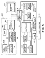
- Fig. 5 is a block diagram showing a whole construction of a serial scanner apparatus.
- the recording head 301 or scanner unit 402 is connected to a head connecting unit 2 in accordance with the use object.
- the recording head 301 is connected to the connecting unit 2.
- Recording data which is required for recording (or printing; hereinafter, referred to as "recording" characters, an image, or the like is transferred from a host computer 11 through an interface (I/F) 10 while being controlled by the host computer 11 and an operation control unit 8.
- a controller 5 receives the recording data and processes it into dot data to record dots onto the recording paper by the recording head 301, and stores the dot data after it was processed into a memory 25. Further, the controller 5 reads out the dot data from the memory 25 while being controlled by the operation control unit 8, supplies the dot data to the recording head 301 through the head connecting line 308 (FPC in Fig. 3) and head connecting unit 2, and records the characters, image, or the like onto the recording paper 311 by dots.
- the roller motor 302 is driven by a motor driver 6 which is controlled by the operation control unit 8 and controller 5 and conveys the recording paper 311.
- the carriage 303 is moved by the carriage motor 307 which is driven by a motor driver 7 that is controlled by the operation control unit 8 and controller 5.
- a sensor 9 detects whether the recording paper 311 or the original to be read has been set on a paper holding base plate (not shown) or not and, further, whether the carriage 303 is located at a start position or not, and the like.
- the operation control unit 8 executes various control operations for the image recording and the original reading in accordance with the various parameters.
- the scanner unit 402 is connected to the head connecting unit 2.
- the scanner unit 402 scans the original in a manner similar to the case where the recording head 301 operated upon recording.
- the LED 401 in the scanner unit 402 exposes the original and the line image sensor 406 having photoelectric converting characteristics detects the reflected light of the characters, image, or the like.
- the signal detected by the line image sensor 406 is amplified by an amplifier 19 to the optimum level among the levels which are treated by an analog/digital converter (hereinafter, simply referred to as an A/D converter) 20 and is inputted to the A/D converter 20.
- the converted digital data is subjected to a shading correction, an edge emphasis, and a binarizing process, which will be explained hereinlater, by an image processing IC 21 and is transferred as image data to the apparatus body.
- the image data is sent to the host computer 11 through a path opposite to that of a flow of the recording data upon recording mentioned above.
- the image data is transferred from the image processing IC 21 and is stored into the memory 25 through the head connecting unit 2, head connecting line 308, and controller 5.
- the controller 5 sends image data to the host computer 11 through the interface 10.
- the controller 5 converts the image data received from the image processing IC 21 to data of a form which can be easily treated by the interface 10 or host computer 11 and transfers while being controlled by the operation control unit 8.
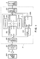
- Fig. 1 is a block diagram in the scanner unit 402.
- the digital data which was A/D converted as mentioned in the foregoing conventional technique is supplied to the image processing IC 21 and is amplified and, after that, it is shading corrected by a shading correction circuit 103.
- the shading corrected data is processed by the comparator 201, thinning-out units 203 and 204, and counter 202 in a manner as described in the foregoing related art.
- the thinning-out unit 203 operates so as to turn on the switch once per 16 pixels.
- the thinning-out unit 204 operates so as to turn on the switch once per 64 pixels.
- the value of the counter 202 is converged to a value corresponding to the background density of the original as mentioned above.
- the counter value can be transferred to the controller 5 through a transfer control unit 102, the head connecting unit 2, and head connecting line 308 by a request from the controller 5 of the apparatus body.
- the controller 5 can set an A input value of the comparator 206, namely, a binarization threshold value through the head connecting line 308, head connecting unit 2, and transfer control unit 102.
- the controller 5 sets various parameters necessary for reading, controls the motor 307 so as to scan the carriage 303 once, and reads the image data as much as one scan.
- the controller 5 After completion of one scan, the controller 5 requests the image processing IC 21 to obtain the value of the counter 202, namely, a background value in a range where it is read by one scan, executes a predetermined process by using the operation control unit 8, and obtains a value smaller than the background value. In the embodiment, a process of 1/2 is executed. The resultant value is compared with the binarization threshold value used in the present one scan. When a difference between them is equal to or less than a predetermined value (in the embodiment, 3), such a value is set to the binarization threshold value of the next reading scan.
- a predetermined value in the embodiment, 3
- 3 is added to the binarization threshold value of the next reading scan.
- 3 is subtracted from the binarization threshold value.
- the threshold value obtained as mentioned above is set to an A input of the comparator 206.
- the paper feed roller 310 rotates and conveys the original by a distance of 128 pixels.
- the next reading scan is performed. By repeating the above operations, a desired range of the original is read and the binarization is performed.
Landscapes
- Engineering & Computer Science (AREA)
- Multimedia (AREA)
- Signal Processing (AREA)
- Facsimile Image Signal Circuits (AREA)
- Image Input (AREA)
Applications Claiming Priority (2)
| Application Number | Priority Date | Filing Date | Title |
|---|---|---|---|
| JP7272394A JPH09116755A (ja) | 1995-10-20 | 1995-10-20 | シリアルスキャナ装置 |
| JP272394/95 | 1995-10-20 |
Publications (2)
| Publication Number | Publication Date |
|---|---|
| EP0769868A2 true EP0769868A2 (de) | 1997-04-23 |
| EP0769868A3 EP0769868A3 (de) | 1998-04-01 |
Family
ID=17513289
Family Applications (1)
| Application Number | Title | Priority Date | Filing Date |
|---|---|---|---|
| EP96307592A Withdrawn EP0769868A3 (de) | 1995-10-20 | 1996-10-18 | Bildverarbeitungssystem |
Country Status (3)
| Country | Link |
|---|---|
| US (1) | US6108456A (de) |
| EP (1) | EP0769868A3 (de) |
| JP (1) | JPH09116755A (de) |
Families Citing this family (6)
| Publication number | Priority date | Publication date | Assignee | Title |
|---|---|---|---|---|
| US6636335B1 (en) * | 1999-06-22 | 2003-10-21 | Mustek Systems, Inc. | Wide image scanner |
| US6796733B2 (en) | 2000-10-31 | 2004-09-28 | International Imaging Materials Inc. | Thermal transfer ribbon with frosting ink layer |
| US7471425B2 (en) * | 2002-04-23 | 2008-12-30 | Yin-Chun Huang | Scanning method by using sheet feed scanner |
| US7829162B2 (en) | 2006-08-29 | 2010-11-09 | international imagining materials, inc | Thermal transfer ribbon |
| US8536087B2 (en) | 2010-04-08 | 2013-09-17 | International Imaging Materials, Inc. | Thermographic imaging element |
| EP4359219A1 (de) | 2021-06-23 | 2024-05-01 | International Imaging Materials Inc. | Thermographisches aufzeichnungselement |
Family Cites Families (5)
| Publication number | Priority date | Publication date | Assignee | Title |
|---|---|---|---|---|
| NL175777C (nl) * | 1977-05-27 | 1984-12-17 | Nederlanden Staat | Schakeling voor de eliminatie van de achtergrondhelderheidsvariatie van een videosignaal. |
| DE3413651C3 (de) * | 1983-04-12 | 1997-11-20 | Canon Kk | Bildsignalverarbeitungsgerät |
| GB2152326B (en) * | 1983-12-26 | 1988-02-17 | Casio Computer Co Ltd | Document reading apparatus utilizing printer mechanism |
| US4593325A (en) * | 1984-08-20 | 1986-06-03 | The Mead Corporation | Adaptive threshold document duplication |
| EP0641115B1 (de) * | 1993-08-30 | 1999-03-24 | Hewlett-Packard Company | Bildabtastkopf für einen thermischen Tintenstrahldrucker |
-
1995
- 1995-10-20 JP JP7272394A patent/JPH09116755A/ja active Pending
-
1996
- 1996-10-16 US US08/733,010 patent/US6108456A/en not_active Expired - Fee Related
- 1996-10-18 EP EP96307592A patent/EP0769868A3/de not_active Withdrawn
Non-Patent Citations (1)
| Title |
|---|
| None |
Also Published As
| Publication number | Publication date |
|---|---|
| US6108456A (en) | 2000-08-22 |
| EP0769868A3 (de) | 1998-04-01 |
| JPH09116755A (ja) | 1997-05-02 |
Similar Documents
| Publication | Publication Date | Title |
|---|---|---|
| US8009931B2 (en) | Real-time processing of grayscale image data | |
| US5790932A (en) | Image forming apparatus for delaying the processing of image data whether the image represented by the image data is a predetermined image | |
| US5363454A (en) | Image processing apparatus | |
| US6108456A (en) | Image processing system | |
| US7175355B2 (en) | Printing apparatus and method with respect to medium | |
| US20030184808A1 (en) | Image processing apparatus and image forming apparatus | |
| US6353481B1 (en) | Technique for correcting printing errors in a shuttle type multifunctional apparatus | |
| JP3204970B2 (ja) | 所要サイズのスキャナをレーザープリンタに接続してそれと異なるサイズでコピーする方法 | |
| US8016499B2 (en) | Printing method with respect to scanning a medium | |
| JP3671682B2 (ja) | 画像認識装置 | |
| JPH0927909A (ja) | 画像読取装置 | |
| KR100218002B1 (ko) | 셔틀 스캐너 방식의 복합기에서 프린팅 영역 판별 방법 | |
| US6658170B1 (en) | Image processing apparatus and image processing method | |
| EP0744860B1 (de) | Bildlese- und Bildaufzeichnungsgerät | |
| JPH09298628A (ja) | 画像読取装置 | |
| JPH11164095A (ja) | スキャナの画像入力方法 | |
| KR100234431B1 (ko) | 셔틀 스캐너 방식 복합기의 스캔 영역 감지 장치 및 감지 방법 | |
| JP2885799B2 (ja) | 画像処理装置 | |
| JP3629959B2 (ja) | 画像認識装置 | |
| KR100277771B1 (ko) | 셔틀스캐닝방식의복합기에서보정용픽셀의위치측정방법 | |
| EP0889634A2 (de) | Dokumentgrösseerfassungsverfahren und -Vorrichtung | |
| JP4204682B2 (ja) | 画像形成装置 | |
| JP3278340B2 (ja) | 画像読取装置及び画像記録装置 | |
| KR100229509B1 (ko) | 셔틀 스캐너 방식 복합기에서 용지 선단 검출 및 정렬방법 | |
| JP3287731B2 (ja) | 画像読取装置 |
Legal Events
| Date | Code | Title | Description |
|---|---|---|---|
| PUAI | Public reference made under article 153(3) epc to a published international application that has entered the european phase |
Free format text: ORIGINAL CODE: 0009012 |
|
| AK | Designated contracting states |
Kind code of ref document: A2 Designated state(s): DE FR GB IT |
|
| PUAL | Search report despatched |
Free format text: ORIGINAL CODE: 0009013 |
|
| AK | Designated contracting states |
Kind code of ref document: A3 Designated state(s): DE FR GB IT |
|
| 17P | Request for examination filed |
Effective date: 19980813 |
|
| 17Q | First examination report despatched |
Effective date: 20020122 |
|
| STAA | Information on the status of an ep patent application or granted ep patent |
Free format text: STATUS: THE APPLICATION HAS BEEN WITHDRAWN |
|
| 18W | Application withdrawn |
Effective date: 20060529 |