EP0769801A2 - Metal halide lamp - Google Patents
Metal halide lamp Download PDFInfo
- Publication number
- EP0769801A2 EP0769801A2 EP96116763A EP96116763A EP0769801A2 EP 0769801 A2 EP0769801 A2 EP 0769801A2 EP 96116763 A EP96116763 A EP 96116763A EP 96116763 A EP96116763 A EP 96116763A EP 0769801 A2 EP0769801 A2 EP 0769801A2
- Authority
- EP
- European Patent Office
- Prior art keywords
- lamp
- metal halide
- halide
- filled
- halide lamp
- Prior art date
- Legal status (The legal status is an assumption and is not a legal conclusion. Google has not performed a legal analysis and makes no representation as to the accuracy of the status listed.)
- Granted
Links
Images


Classifications
-
- H—ELECTRICITY
- H01—ELECTRIC ELEMENTS
- H01J—ELECTRIC DISCHARGE TUBES OR DISCHARGE LAMPS
- H01J61/00—Gas-discharge or vapour-discharge lamps
- H01J61/02—Details
- H01J61/12—Selection of substances for gas fillings; Specified operating pressure or temperature
- H01J61/18—Selection of substances for gas fillings; Specified operating pressure or temperature having a metallic vapour as the principal constituent
-
- H—ELECTRICITY
- H01—ELECTRIC ELEMENTS
- H01J—ELECTRIC DISCHARGE TUBES OR DISCHARGE LAMPS
- H01J61/00—Gas-discharge or vapour-discharge lamps
- H01J61/82—Lamps with high-pressure unconstricted discharge having a cold pressure > 400 Torr
- H01J61/827—Metal halide arc lamps
-
- H—ELECTRICITY
- H01—ELECTRIC ELEMENTS
- H01J—ELECTRIC DISCHARGE TUBES OR DISCHARGE LAMPS
- H01J61/00—Gas-discharge or vapour-discharge lamps
- H01J61/02—Details
- H01J61/12—Selection of substances for gas fillings; Specified operating pressure or temperature
- H01J61/125—Selection of substances for gas fillings; Specified operating pressure or temperature having an halogenide as principal component
-
- H—ELECTRICITY
- H01—ELECTRIC ELEMENTS
- H01J—ELECTRIC DISCHARGE TUBES OR DISCHARGE LAMPS
- H01J61/00—Gas-discharge or vapour-discharge lamps
- H01J61/84—Lamps with discharge constricted by high pressure
- H01J61/86—Lamps with discharge constricted by high pressure with discharge additionally constricted by close spacing of electrodes, e.g. for optical projection
Definitions
- the present invention relates to a metal halide lamp used as a light source of a liquid crystal projector and the like.
- liquid crystal projectors or the like are known as means for enlarging and projecting an image of characters, figures, etc. Since a certain optical output is required for such an image projector, a metal halide lamp, which has a high luminous efficacy, is widely used as a light source for the image projector in general.
- a metal halide lamp which has a high luminous efficacy, is widely used as a light source for the image projector in general.
- an iodide of Nd, Dy, and Cs has been generally used as a halide to be filled in an arc tube.
- the lamp in which the iodide of Nd, Dy and Cs is filled (hereinafter described as Dy-Nd-Cs-I series lamp), as disclosed in Japanese Unexamined Patent Publication No. 3-219546, has an excellent luminous efficacy, however, it has the disadvantage that devitrification occurs in an early stage of its lifetime, particularly because of high reactivity between neodymium iodide (NdI 3 ) and silica glass of the arc tube.
- the lack of transparency decreases the intensity of light beam, reduces the luminous intensity and disperses the light beam, resulting in nonuniform illumination intensity and reduced brightness on a screen of the liquid crystal projector.
- the drawback of the Dy-Nd-Cs-I lamp as use as the light source of a liquid crystal projector is that the lifetime of the liquid crystal projector is short.
- Luminous characteristics of metal halide lamp containing rare earth halide discloses that a light source having a high luminous efficacy can be obtained by combining a rare earth halide with a halide of Tl or In.
- the low correlated color temperature of the light source disclosed therein is unsuitable for a light source of such things as a liquid crystal projector.
- An example of a light source disclosed therein is a metal halide lamp in which InI and TmI 3 are filled, and a correlated color temperature estimated from the relative spectral distribution diagram disclosed therein is about 4 500 K.
- a white color reference for an image projector such as liquid crystal projectors is about 9000 K.
- An object of the present invention is to provide a metal halide lamp as an alternative of a prior art Dy-Nd-Cs-I series lamp or In-Tm-I series lamp.
- the metal halide lamp has an emission spectrum distributed all over the visual inspection range, a high luminous efficacy, an appropriate color temperature and a long lifetime.
- a metal halide lamp of the present invention comprises
- the halide of Tb, Dy, Ho, Er, Tm, or a mixture of said Tb, Dy, Ho, Er, Tm is filled to such an extent that an evaporable amount of said halide depending on the temperature of said halide is the minimum filler amount and 3.0 mg/cc of said halide is the maximum thereof.
- lighting is conducted with a lamp power having a tube wall load of 48 W/cm 2 to 62 W/cm 2 .
- filled materials in the light transmitting container are excited by electromagnetic wave externally supplied and begin to emit.
- a halogen of the halide of In is iodine or bromine.
- a halogen of the halide of a rare earth element is iodine or bromine.
- the lamp In the metal halide lamp , the lamp is operated by AC current.
- a pair of electrodes to be electrically connected to an external power supply is arranged so that a distance between the pair of electrodes is 5 mm or less.
- a first problem of the prior art Dy-Nd-Cs-I series lamp is that, since the reactivity of NdI 3 and silica glass of an arc tube is intense, devitrification of a arc tube occurs at an early stage of its lifetime. This problem can be solved if a material having a lower devitrification level (weaker reactivity with silica glass) than that of NdI 3 is used for the filler of the lamp.
- devitrification levels of various metal halides are evaluated firstly by the following devitrification evaluation test.
- an ampoule composed of a tube made of silica glass, having a content volume of 5 cc and filled with 10 mg of metal halide, is heated at 1, 100 °C for 100 hours, and then a total transmittance of the ampoule is measured in order to evaluate the devitrification characteristic of the metal halide.
- the ratios (%) of the total transmittances of the ampoules after heating (after the test) to the total transmittances thereof measured before heating are shown in Table 1. A larger percentage means a lower level devitrification. Blanks in the table indicate that evaluation was not conducted.
- the total transmittances of ampoules filled with TbI 3 , DyI 3 , HoI 3 ErI 3 , TmI 3 , InI, SnI 3 , DyBr 3 , TmBr 3 , InBr and SnBr 3 , respectively, are larger than the total transmittance of an ampoule filled with NdI3, and indicate a low level devitrification characteristic.
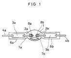
- FIG. 1 is a view showing a metal halide lamp of a first embodiment of the invention.
- reference numeral 1 denotes a light transmitting container as an arc tube made of quartz, at both ends of which sealing portions 6a, 6b are formed.
- metal foil conductors 3a, 3 b made of molybdenum are tightly attached.
- electrodes 2a, 2b, and outer lead wires 4a, 4b made of molybdenum are electrically connected, .
- the electrodes 2a, 2b are composed of tungsten rods 7a, 7b and tungsten coils 8a, 8b, respectively.
- the coils 8a, 8b are electrically fixed to tip portions of the tungsten rods 7a, 7b by welding, and serve as radiators of the electrodes 2a, 2b.
- the electrodes 2a, 2b are arranged in the arc tube 1 so as to face each other and maintain a distance of 3.5 ⁇ 0.5 mm therebetween.
- the arc tube 1 is nearly spherical, and has an inner diameter of about 10.8 mm, an inner volume of about 0.7 cc, and an inner surface area of about 3.6 cm 2 , in which 0.4 mg (0.57 mg/cc) of InI as a filling material, 1 mg (1.43 mg/cc) of HoI 3 as a rare earth iodide, 35 mg of Hg as a buffer gas, and 200 mbar of Ar as a start-up rare gas are filled.
- the metal halide lamp having the above- mentioned construction was supplied with electric power via external lead wires 4a, 4b to be lit with a rated lamp power of 200 W (tube wall load: 55 W/cm 2 ) and the emission characteristic was evaluated.
- FIG. 2 is a diagram showing a spectrum distribution of the metal halide lamp of this embodiment.
- the correlated color temperature and luminous efficacy of this case were respectively about 5500 K and about 87 lm/W. Rich emission is seen all across the visible range. The emission in the red color range is particularly rich.
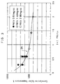
- FIG. 3 is a diagram showing the relation between the filler amount (mg) of InI per unit volume (axis of abscissa) and correlation color temperature (K) (axis of ordinate) wherein filler amounts of HoI 3 are taken as a parameter.
- Three marks ⁇ , ⁇ , ⁇ in FIGs. indicate lamps in which the filler amounts of HoI 3 are 0.57, 1.43 and 2.86 mg/cc, respectively.
- the correlated color temperature highly depends on the filler amounts of InI, as shown in curve 3A in the figure.
- the effect of filler amounts of HoI 3 on the correlation color temperature is relatively low. This is caused by the fact that InI generally conducts an unsaturated action, and HoI 3 generally conducts a saturated action.
- the correlated color temperature required for use as a light source depends on the usage purpose. When it is used for a light source of a liquid crystal projector or like apparatus, it is preferable that the correlated color temperature of the light source is about 4500 K or more. When the temperature is less than 4500 K, such bad conditions is occurred that the white color temperature on a screen becomes slightly yellow color temperature. It is preferable that the correlated color temperature of the light source is about 9000 K which is used as a white color reference in many liquid crystal projector or like apparatus. Results provided in FIG. 3show that a preferable filler amount of InI in correspondence to the requirement of such various relatively high correlated color temperatures is 0.1 mg/cc to 1.5 mg/cc in the metal halide lamp of the embodiment.
- Lamps in which each amount of InI is different and the other constructive details are the same as those of the metal halide lamp of the embodiment of FIG. 1, are operated by various powers and the correlated color temperatures of the lamps are detected.
- the results are shown in FIG. 14.
- the curves 14A, 14B, 14C show respectively the relations between the correlated color temperature and the filler amount of InI under 175 W (tube wall load: about 48 W/cm 2 ), 200 W (tube wall load: about 55 W/cm 2 ), and 225 W (tube wall load: about 62 W/cm 2 ).
- preferable correlated color temperature of about 4500 K - 9000 K can be obtained by such filler amount of InI of 0.1 mg/cc to 1.5 mg/cc even for different tube wall loads. But the higher the tube wall load is, the lower the correlated color temperature becomes. While the correlated color temperature is about 6800 K at a tube wall load of 55 W/cm 2 when the filler amount of InI is 0.57 mg/cc,the correlated color temperature is about 5800 K at a tube wall load of 62 W/cm 2 . But the more the filler amount of InI is, the less such lowering of the color temperature becomes.
- the filler amount of InI is about 1.5 mg/cc
- the variation ratio of the correlated color temperature against such change of tube wall load of 55 W/cm 2 to 62 W/cm 2 is less than 5 % and it can be negligible.
- Such results show that the correlated color temperature of about 4500 K or more can be obtained by making the filler amount of InI being 1. 5 mg/cc or less irrespective of amount of the tube wall load.
- the metal halide lamp of the embodiment was used as a light source for an optical system as shown in FIG. 4 to evaluate a maintenance factor of screen 13 illuminance to lighting time.
- reference numeral 10 denotes a light source
- reference numeral 11 denotes a converging mirror which reflects and converges light radiated from the light source 10
- reference numeral 12 denotes a projection lens system which projects the light converged by the converging mirror on the screen 13.
- Evaluation results are shown in FIG. 5 (curve 5A).
- the axis of abscissa indicates lighting time and the axis of ordinate indicates the maintenance factor of an average of illuminances of 13 points on the screen 13.
- FIG. 6 is a diagram showing a spectrum distribution of the metal halide lamp of the embodiment.
- the correlated color temperature and luminous efficacy in the case are about 6400 K and about 94 lm/W, respectively.
- the lamp wherein TmI 3 replaces HoI 3 is characterized by having a higher luminous efficacy than that of the embodiment. On the other hand, emission in the red color range is less satisfactory.
- the lamp is equivalent to the lamp wherein HoI 3 is filled
- the correlated color temperatures of the lamp of the present embodiment plotted in FIG. 3 fit to curve 3A which relates filler amounts of InI to correlated color temperatures.
- a preferable filler amount of INI in the lamp in which TmI 3 is used in lieu of HoI 3 in the present embodiment is 0.1 mg/cc to 1. 5 mg/cc, the same as in embodiment 1.
- FIG. 7 is a diagram (curve 7A) showing changes in maintenance factor of an average of illuminances of 13 points on the screen 13 to lighting time when the lamp of the present embodiment was used as a light source for the optical system shown in FIG. 4.
- curves 7B and 7C respectively.
- the average illuminance of the screen in the prior art Dy-Nd-Cs-I lamp after about 1 400 hours of lighting decreased to 50 % of that of an early stage of use, while the average illuminance of the lamp of the present embodiment, even after 2000 hours of lighting, maintains 60 % of that of the early stage of use.
- FIG. 7B it was newly found that lifetime is shortened with increase of filler amount of TmI 3 .
- the tendency was also observed in the HoI 3 -filled lamp, which is described in embodiment 1. Accordingly as small as possible filler amount of TmI 3 is preferable for lifetime.
- the minimum amount of TmI 3 is such amount being possible to evaporate (As the vapor pressures of TmI 3 and HoI 3 are low, the whole amount of filler does not evaporate).
- Meawhile an evaporable amount of said halide is determined by the temperature of said halide.
- the coolest temperature of the lamp of the embodiment is about 1000 K as like other general metal halide lamps and the saturation vapor pressure of TmI 3 at this temperature is about 4 ⁇ 10 -5 atm and therefore the amount of the evaporated TmI 3 within the lamp of 0.7 cc is about 0.0001 mg on the basis equation of gas state .
- FIG. 8 is a diagram showing the relationship between the filler amount of HoI 3 and the luminous efficacy in a lamp wherein HoI 3 replaced TmI 3 in the present embodiment.
- FIG. 9 is a diagram showing a spectrum distribution of the metal halide lamp of the present embodiment.
- the correlated color temperature and luminous efficacy in the case are about 7000 K and about 82 lm/W, respectively.
- the lamp wherein TbI 3 replaces HoI 3 is characterized by having a higher correlation color temperature indicated by the present embodiment.
- the correlated color temperature and luminous efficacy of another lamp of the present embodiment wherein 0.6 mg (0.86 mg/cc) of InI, and 2 mg (2.86 mg/cc) of TbI 3 are filled, are about 6300 K and about 80 lm/W, respectively.
- a preferable filler amount of InI in the lamp is 0.1 mg/cc to 1.5 mg/cc, the same as in the lamp of embodiment 1.
- FIG. 10 is a diagram showing a spectrum distribution of the metal halide lamp of the embodiment.
- the correlated color temperature and luminous efficacy in the case are about 5000 K and about 86 lm/W, respectively.
- the lamp of the present embodiment wherein ErI 3 is filled indicates the same emission distribution as that with HoI 3 . Given this characteristic, ErI 3 can completely replace HoI 3 .
- a preferable filler amount of InI is 0.1 mg/cc to 1.5 mg/cc, the same as in the lamp of embodiment 1.
- FIG. 11 is a diagram showing a spectrum distribution of the metal halide lamp of the present embodiment.
- the correlated color temperature and luminous efficacy in the case are about 6100 K and about 831 m/W, respectively.
- the lamp wherein TbI 3 is added to HoI 3 is characterized by emission distribution in which characteristics of both TbI 3 and HoI 3 are added. Emission around 500 nm wavelength, which is richer than that of the lamp in which only TbI 3 is filled, is an effect produced by TbI 3 , and emission around the red color range, which is richer than that of the lamp in which only TbI 3 is filled, is an effect produced by HoI 3 .
- FIG. 12 is a diagram showing a spectrum distribution of the metal halide lamp of the present embodiment.
- the correlated color temperature and luminous efficacy in the case are about 5300 K and about 801 m/W, respectively.
- InI InI
- InBr The replacement of InI by InBr is not limited to the case of the combination with HoI 3 , as indicated in the present embodiment. It is possible in combinations with TbI 3 , DyI 3 , ERI 3 , TmI 3 as well as a mixture of these iodides. Additionally, bromides may be used in lieu of iodides, and iodides may be combined with bromides.
- FIG. 13 is a diagram showing a spectrum distribution of the metal halide lamp of the present embodiment.
- the correlated color temperature and luminous efficacy in the case are about 7200 K and about 74 lm/W, respectively.
- a lamp in which HoBr3 replaced HoI 3 is characterized by a higher correlated color temperature than that of the present embodiment. Emission around 440 nm wavelength largely increased. The luminous efficacy decreased by 10 % to a level equivalent to that of the conventional Dy-Nd-Cs-I lamp.
- TmI 3 -filled lamp With respect to the TmI 3 -filled lamp described in embodiment 2, another lamp in which 1 mg (1.43 mg/cc) of TmBr 3 was filled in lieu of TmI 3 , it has a correlated color temperature of about 8600 K and a luminous efficacy of about 81 lm/W. The spectrum distribution of the lamp is shown in FIG. 14.
- a highly efficient metal halide lamp satisfying the requirement for various relatively high correlated color temperatures can be realized.
- the filler amount of said halide of the rare earth is in such range that an evaporable amount of said halide depending on the temperature of said halide is the minimum filler amount and 3.0 mg/cc of said halide is the maximum thereof , a metal halide lamp having a further extended lifetime can be realized.
- the arc length is 3.5 ⁇ 0.5mm, but when the arc length is 5 mm or less , same merits are obtained.
- the arc length is more than 5 mm, the efficacy increases but the correlated color temperature decreases.
- the luminous efficacy was less than 70 lm/W.
- a halide of Sn which indicated a low devitrification in the devitrification test results, and a iodide of In were combined, a luminous efficacy of 701 m/W or more could be obtained, but because of the low luminance, the lamp was unsuitable as a light source for a liquid crystal projector or the like.
- an economical light source having a good luminous efficacy and an emission spectrum covering the visible range, which can satisfy the requirement for various relatively high correlated color temperatures.
- This is made possible by in addition to a start-up rare gas , combining at least a halide of In and a halide of a rare earth element including Tb, Dy, Ho, Er and Tm, or a halide of a mixture of those selected from these elements.
- the currents applied to the lamps in the above mentioed embodiments are rectangular waveform of 270 Hz. It is preferable to use AC as the currents applied to the lamps in the present invention.
Landscapes
- Discharge Lamp (AREA)
- Manufacture Of Electron Tubes, Discharge Lamp Vessels, Lead-In Wires, And The Like (AREA)
- Discharge Lamps And Accessories Thereof (AREA)
Abstract
Description
- The present invention relates to a metal halide lamp used as a light source of a liquid crystal projector and the like.
- Recently, liquid crystal projectors or the like are known as means for enlarging and projecting an image of characters, figures, etc. Since a certain optical output is required for such an image projector, a metal halide lamp, which has a high luminous efficacy, is widely used as a light source for the image projector in general. In this kind of metal halide lamp, as disclosed in Japanese Unexamined Patent Publication No. 3-219546 for example, an iodide of Nd, Dy, and Cs has been generally used as a halide to be filled in an arc tube.
- The lamp in which the iodide of Nd, Dy and Cs is filled (hereinafter described as Dy-Nd-Cs-I series lamp), as disclosed in Japanese Unexamined Patent Publication No. 3-219546, has an excellent luminous efficacy, however, it has the disadvantage that devitrification occurs in an early stage of its lifetime, particularly because of high reactivity between neodymium iodide (NdI3) and silica glass of the arc tube. The lack of transparency decreases the intensity of light beam, reduces the luminous intensity and disperses the light beam, resulting in nonuniform illumination intensity and reduced brightness on a screen of the liquid crystal projector. Specifically, the drawback of the Dy-Nd-Cs-I lamp as use as the light source of a liquid crystal projector is that the lifetime of the liquid crystal projector is short.
- Recently from the viewpoint of saving energy, there is a demand for a light source having a higher luminous efficacy than that of the Dy-Nd-Cs lamp. "Luminous characteristics of metal halide lamp containing rare earth halide" (Journal of Lighting Society, vol. 65 No. 10, 1981, page 17) discloses that a light source having a high luminous efficacy can be obtained by combining a rare earth halide with a halide of Tl or In. However, the low correlated color temperature of the light source disclosed therein is unsuitable for a light source of such things as a liquid crystal projector. An example of a light source disclosed therein is a metal halide lamp in which InI and TmI3 are filled, and a correlated color temperature estimated from the relative spectral distribution diagram disclosed therein is about 4 500 K. On the other hand, a white color reference for an image projector such as liquid crystal projectors is about 9000 K.
- An object of the present invention is to provide a metal halide lamp as an alternative of a prior art Dy-Nd-Cs-I series lamp or In-Tm-I series lamp. The metal halide lamp has an emission spectrum distributed all over the visual inspection range, a high luminous efficacy, an appropriate color temperature and a long lifetime.
- A metal halide lamp of the present invention comprises
- a light transmitting container in which, in addition to a start-up rare gas, at least a halide of In, and a halide of Tb, Dy, Ho, Er, Tm, or a mixture of said Tb, Dy, Ho, Er, Tm are filled, wherein
- 0.1 mg/cc to 1.5 mg/cc of the halide of In is filled.
- In the metal halide lamp, the halide of Tb, Dy, Ho, Er, Tm, or a mixture of said Tb, Dy, Ho, Er, Tm is filled to such an extent that an evaporable amount of said halide depending on the temperature of said halide is the minimum filler amount and 3.0 mg/cc of said halide is the maximum thereof.
- In the metal halide lamp , lighting is conducted with a lamp power having a tube wall load of 48 W/cm2 to 62 W/cm2.
- In the metal halide lamp , filled materials in the light transmitting container are excited by electromagnetic wave externally supplied and begin to emit.
- In the metal halide lamp , a halogen of the halide of In is iodine or bromine.
- In the metal halide lamp , a halogen of the halide of a rare earth element is iodine or bromine.
- In the metal halide lamp , the lamp is operated by AC current.
- In the metal halide lamp , a pair of electrodes to be electrically connected to an external power supply is arranged so that a distance between the pair of electrodes is 5 mm or less.
-
- FIG. 1 is a view showing the construction of a metal halide lamp of an
embodiment 1 of the invention; - FIG. 2 is a diagram showing a distribution of the metal halide lamp of the
embodiment 1 of the invention; - FIG. 3 is a diagram showing the relation between amount of iodide filled in the lamp and correlated color temperature in the
embodiment 1 of the invention; - FIG. 4 is a view showing the construction of an optical system used for lifetime evaluation of a metal halide lamp of the invention;
- FIG. 5 is a diagram showing the relation between lighting time and illuminace maintenance factor of the metal halide lamp of the
embodiment 1 of the invention; - FIG. 6 is a diagram showing an emission distribution of a metal halide lamp of an
embodiment 2 of the invention; - FIG. 7 is a diagram showing the relation between lighting time and illuminance maintenance factor of the metal halide lamp of the
embodiment 2 of the invention; - FIG. 8 is a diagram showing the relation between amount of iodide filled in the lamp and correlated color temperature in the
embodiment 2 of the invention; - FIG. 9 is a diagram showing an emission distribution of a metal halide lamp of an embodiment 3 of the invention;
- FIG. 10 is a diagram showing an emission distribution of a metal halide lamp of an embodiment 4 of the invention;
- FIG. 11 is a diagram showing an emission distribution of a metal halide lamp of an embodiment 5 of the invention;
- FIG. 12 is a diagram showing an emission distribution of a metal halide lamp of an embodiment 6 of the invention;
- FIG. 13 is a diagram showing an emission distribution of a metal halide lamp of an embodiment 7 of the invention;
- FIG. 14 is a diagram showing a relation between the tube wall load and the correlated color temperature in the
embodiment 1 of the invention. - 1
- arc tube
- 2a
- electrode
- 2b
- electrode
- 10
- light source
- 11
- light beam condensing mirror
- 12
- projection lens system
- 13
- screen
- Referring to the drawings, preferred embodiments of the invention are described in detail below.
- A first problem of the prior art Dy-Nd-Cs-I series lamp is that, since the reactivity of NdI3 and silica glass of an arc tube is intense, devitrification of a arc tube occurs at an early stage of its lifetime. This problem can be solved if a material having a lower devitrification level (weaker reactivity with silica glass) than that of NdI3 is used for the filler of the lamp.
- From this viewpoint, devitrification levels of various metal halides are evaluated firstly by the following devitrification evaluation test. In the devitrification test, an ampoule composed of a tube made of silica glass, having a content volume of 5 cc and filled with 10 mg of metal halide, is heated at 1, 100 °C for 100 hours, and then a total transmittance of the ampoule is measured in order to evaluate the devitrification characteristic of the metal halide. The ratios (%) of the total transmittances of the ampoules after heating (after the test) to the total transmittances thereof measured before heating are shown in Table 1. A larger percentage means a lower level devitrification. Blanks in the table indicate that evaluation was not conducted.
TABLE 1 Material Total transmittance(%) Material Total transmittance(%) NdI3 94.6 NdBr3 97.0 TbI3 98.0 TbBr3 DyI3 94.8 DyBr3 99.0 HoI3 98.1 HoBr3 ErI3 98.6 ErBr3 TmI3 98.7 TmBr3 99.0 InI 99.0 InBr SnI3 99.0 SnBr3 99.0 - As shown in Table 1, the total transmittances of ampoules filled with TbI3, DyI3, HoI3 ErI3, TmI3, InI, SnI3, DyBr3, TmBr3, InBr and SnBr3, respectively, are larger than the total transmittance of an ampoule filled with NdI3, and indicate a low level devitrification characteristic.
- Accordingly various characteristics of combinations of these materials with a low level devitrification characteristic are investigated. As a result, as described below, excellent lifetime and luminous efficacy characteristics are obtained by adding a halide of Tb, Dy, Ho, Er, or Tm, or a mixture of these, to a halide of In.
- FIG. 1 is a view showing a metal halide lamp of a first embodiment of the invention. In FIG. 1,
reference numeral 1 denotes a light transmitting container as an arc tube made of quartz, at both ends of which sealingportions portions metal foil conductors metal foil conductors electrodes outer lead wires 4a, 4b made of molybdenum are electrically connected, . - The
electrodes tungsten rods tungsten coils coils tungsten rods electrodes electrodes arc tube 1 so as to face each other and maintain a distance of 3.5 ± 0.5 mm therebetween. - The
arc tube 1 is nearly spherical, and has an inner diameter of about 10.8 mm, an inner volume of about 0.7 cc, and an inner surface area of about 3.6 cm2, in which 0.4 mg (0.57 mg/cc) of InI as a filling material, 1 mg (1.43 mg/cc) of HoI3 as a rare earth iodide, 35 mg of Hg as a buffer gas, and 200 mbar of Ar as a start-up rare gas are filled. - The metal halide lamp having the above- mentioned construction was supplied with electric power via
external lead wires 4a, 4b to be lit with a rated lamp power of 200 W (tube wall load: 55 W/cm2) and the emission characteristic was evaluated. - FIG. 2 is a diagram showing a spectrum distribution of the metal halide lamp of this embodiment. The correlated color temperature and luminous efficacy of this case were respectively about 5500 K and about 87 lm/W. Rich emission is seen all across the visible range. The emission in the red color range is particularly rich.
- For the purpose of comparison, a lamp in which 1 mg of DyI3, 1 mg of NDI3, and 1 mg of CsI are filled in lieu of InI and HoI3, and the other constructive details are the same as those of the metal halide lamp of the embodiment of FIG. 1 (hereinafter described as Dy-Nd-Cs-I lamp) was evaluated. The luminous efficacy of the comparative metal halide lamp when being lit with the rated power was 77 lm/W. These results indicate that the metal halide lamp of this embodiment has a good luminous efficacy.
- Next, various different lamps were fabricated wherein filler amounts of InI and HoI3 differed and the other constructive details were the same as those of the metal halide lamp of the embodiment of FIG. 1. Examination was conducted on luminous efficacy of these lamps at the time they are operated with the rated power and further, on basic characteristics of the metal halide lamp in which InI and HoI3 are filled. The results will be described referring to FIGs. 3, 4 and 5.
- FIG. 3 is a diagram showing the relation between the filler amount (mg) of InI per unit volume (axis of abscissa) and correlation color temperature (K) (axis of ordinate) wherein filler amounts of HoI3 are taken as a parameter. Three marks ●, ○, □ in FIGs. indicate lamps in which the filler amounts of HoI3 are 0.57, 1.43 and 2.86 mg/cc, respectively.
- As seen in FIG. 3, it was found that the correlated color temperature highly depends on the filler amounts of InI, as shown in
curve 3A in the figure. However, the effect of filler amounts of HoI3 on the correlation color temperature is relatively low. This is caused by the fact that InI generally conducts an unsaturated action, and HoI3 generally conducts a saturated action. - The correlated color temperature required for use as a light source depends on the usage purpose. When it is used for a light source of a liquid crystal projector or like apparatus, it is preferable that the correlated color temperature of the light source is about 4500 K or more. When the temperature is less than 4500 K, such bad conditions is occurred that the white color temperature on a screen becomes slightly yellow color temperature. It is preferable that the correlated color temperature of the light source is about 9000 K which is used as a white color reference in many liquid crystal projector or like apparatus. Results provided in FIG. 3show that a preferable filler amount of InI in correspondence to the requirement of such various relatively high correlated color temperatures is 0.1 mg/cc to 1.5 mg/cc in the metal halide lamp of the embodiment.
- Additionally, it is apparent from the following description, that the range of preferable filler amounts of InI in correspondence to the requirement of such various relatively high correlated color temperature can apply to other lamp which has different tube wall load from that of the lamp of this embodiment.
- Lamps in which each amount of InI is different and the other constructive details are the same as those of the metal halide lamp of the embodiment of FIG. 1, are operated by various powers and the correlated color temperatures of the lamps are detected. The results are shown in FIG. 14. In the FIG. 14 the
curves 14A, 14B, 14C show respectively the relations between the correlated color temperature and the filler amount of InI under 175 W (tube wall load: about 48 W/cm2), 200 W (tube wall load: about 55 W/cm2), and 225 W (tube wall load: about 62 W/cm2). As a result it is apparent that preferable correlated color temperature of about 4500 K - 9000 K can be obtained by such filler amount of InI of 0.1 mg/cc to 1.5 mg/cc even for different tube wall loads. But the higher the tube wall load is, the lower the correlated color temperature becomes. While the correlated color temperature is about 6800 K at a tube wall load of 55 W/cm2 when the filler amount of InI is 0.57 mg/cc,the correlated color temperature is about 5800 K at a tube wall load of 62 W/cm2. But the more the filler amount of InI is, the less such lowering of the color temperature becomes. When the filler amount of InI is about 1.5 mg/cc, the variation ratio of the correlated color temperature against such change of tube wall load of 55 W/cm2 to 62 W/cm2 is less than 5 % and it can be negligible. Such results show that the correlated color temperature of about 4500 K or more can be obtained by making the filler amount of InI being 1. 5 mg/cc or less irrespective of amount of the tube wall load. - Next, the metal halide lamp of the embodiment was used as a light source for an optical system as shown in FIG. 4 to evaluate a maintenance factor of
screen 13 illuminance to lighting time. In FIG. 4,reference numeral 10 denotes a light source,reference numeral 11 denotes a converging mirror which reflects and converges light radiated from thelight source 10 andreference numeral 12 denotes a projection lens system which projects the light converged by the converging mirror on thescreen 13. Evaluation results are shown in FIG. 5 (curve 5A). In FIG. 5, the axis of abscissa indicates lighting time and the axis of ordinate indicates the maintenance factor of an average of illuminances of 13 points on thescreen 13. For the purpose of comparison, the results on the Dy-Nd-Cs-I lamp are also indicated (curve 5B). From these results, it is newly demonstrated that the metal halide lamp comprising InI and HoI3 has a longer lifetime than that of the prior art lamp wherein NdI3 is filled. These results are shown in Table 1 above, which support the results of the devitrification evaluation test. - Next, a lamp wherein 1 mg (1.43 mg/cc) of TmI3 is filled in lieu of HoI3, and the other constructive details are the same as those of the metal halide lamp of the embodiment of FIG. 1 will be described below.
- FIG. 6 is a diagram showing a spectrum distribution of the metal halide lamp of the embodiment. The correlated color temperature and luminous efficacy in the case are about 6400 K and about 94 lm/W, respectively.
- The lamp wherein TmI3 replaces HoI3 is characterized by having a higher luminous efficacy than that of the embodiment. On the other hand, emission in the red color range is less satisfactory.
- With respect to the correlated color temperature, the lamp is equivalent to the lamp wherein HoI3 is filled The correlated color temperatures of the lamp of the present embodiment plotted in FIG. 3 fit to
curve 3A which relates filler amounts of InI to correlated color temperatures. Accordingly, a preferable filler amount of INI in the lamp in which TmI3 is used in lieu of HoI3 in the present embodiment (in which a relatively high correlated color temperature is attained, which can not be attained in the prior art In-Tm-I series lamp) is 0.1 mg/cc to 1. 5 mg/cc, the same as inembodiment 1. - The lamp of the present embodiment is also characterized by a long lifetime. The same as FIG. 5, FIG. 7 is a diagram (
curve 7A) showing changes in maintenance factor of an average of illuminances of 13 points on thescreen 13 to lighting time when the lamp of the present embodiment was used as a light source for the optical system shown in FIG. 4. In addition, the results on a lamp of the present embodiment wherein 2 mg of TmI3 is filled, and the prior art Dy-Nd-Cs-I lamp are also indicated (curves embodiment 1. Accordingly as small as possible filler amount of TmI3 is preferable for lifetime. The minimum amount of TmI3 is such amount being possible to evaporate (As the vapor pressures of TmI3 and HoI3 are low, the whole amount of filler does not evaporate). Meawhile an evaporable amount of said halide is determined by the temperature of said halide. The coolest temperature of the lamp of the embodiment is about 1000 K as like other general metal halide lamps and the saturation vapor pressure of TmI3 at this temperature is about 4×10⁻⁵ atm and therefore the amount of the evaporated TmI3 within the lamp of 0.7 cc is about 0.0001 mg on the basis equation of gas state . However, because such an ultra small amount can not be weighed, an amount of 0.01 mg is a practical value. The maximum limitation amount is 2 mg (= about 3 mg/cc) from FIG. 7. This preferable range of filler amount of TmI 3 can be also applied to the HoI3-filled lamp which is described in the foregoingembodiment 1, from the same reason. - Additionally, even when a different amount of TmI3 or HoI3 is filled, TmI3 and HoI3 conduct saturation action, so that luminous efficacy is not adversely affected. FIG. 8 is a diagram showing the relationship between the filler amount of HoI3 and the luminous efficacy in a lamp wherein HoI3 replaced TmI3 in the present embodiment.
- Next, a lamp wherein 1 mg (1.43 mg/cc) of TbI3 is filled in lieu of HoI3, and the other constructive details are the same as those of the metal halide lamp of the embodiment of FIG. 1 will be described below.
- FIG. 9 is a diagram showing a spectrum distribution of the metal halide lamp of the present embodiment. The correlated color temperature and luminous efficacy in the case are about 7000 K and about 82 lm/W, respectively.
- The lamp wherein TbI3 replaces HoI3 is characterized by having a higher correlation color temperature indicated by the present embodiment. The emission of around 500 nm wavelength, which is richer than the red color range, contributes to the higher correlation color temperature.
- Additionally, the correlated color temperature and luminous efficacy of another lamp of the present embodiment, wherein 0.6 mg (0.86 mg/cc) of InI, and 2 mg (2.86 mg/cc) of TbI3 are filled, are about 6300 K and about 80 lm/W, respectively.
- In the lamp of the present embodiment, a preferable filler amount of InI in the lamp is 0.1 mg/cc to 1.5 mg/cc, the same as in the lamp of
embodiment 1. - From the results of the devitrification test shown in Table 1 and the results of
embodiments - Next, a lamp wherein 0.6 mg (0.86 mg/cc) of InI and 2 mg (2.86 mg/cc) of ErI3 in lieu of HoI3 are filled, and the other constructive details are the same as those of the metal halide lamp of the embodiment of FIG. 1, will be described below.
- FIG. 10 is a diagram showing a spectrum distribution of the metal halide lamp of the embodiment. The correlated color temperature and luminous efficacy in the case are about 5000 K and about 86 lm/W, respectively.
- The lamp of the present embodiment wherein ErI3 is filled indicates the same emission distribution as that with HoI3. Given this characteristic, ErI3 can completely replace HoI3.
- In the lamp of the present embodiment, a preferable filler amount of InI is 0.1 mg/cc to 1.5 mg/cc, the same as in the lamp of
embodiment 1. - A similar emission characteristic can also be obtained in a lamp of the present embodiment wherein Dy3 replaces ErI3. However, as apparent from Table 1 of devitrification test results, devitrification property is relatively strong, so that replacement with DyI3 slightly diminishes a prominent effect to lifetime.
- Next, a lamp will be described below wherein 0.6 mg (0.86 mg/cc) of InI and 1mg (1.43 mg/cc) of HoI3 are filled, and 1 mg (1.43 mg/cc) of TbI3 is added, and the other constructive details are the same as those of the metal halide lamp of the embodiment of FIG. 1.
- FIG. 11 is a diagram showing a spectrum distribution of the metal halide lamp of the present embodiment. The correlated color temperature and luminous efficacy in the case are about 6100 K and about 831 m/W, respectively.
- The lamp wherein TbI3 is added to HoI3 is characterized by emission distribution in which characteristics of both TbI3 and HoI3 are added. Emission around 500 nm wavelength, which is richer than that of the lamp in which only TbI3 is filled, is an effect produced by TbI3, and emission around the red color range, which is richer than that of the lamp in which only TbI3 is filled, is an effect produced by HoI3.
- The effects of such addition can be also attained by other combinations than the combination of HoI3 and TbI3. By appropriately combining TbI3, DyI3, HoI3, ErI3 and TmI3, a lamp which has unique characteristics can be attained. For example, in the case of a combination of HoI3 and TmI3, emission of TmI3 in the red color range, which is slightly less satisfactory, is improved by HoI3, and a higher luminous efficacy than that of a lamp in which only HoI3 is filled is produced by TmI3.
- Next, a lamp wherein 0.4 mg (0.57 mg/cc) of InBr is filled in lieu of InI, and the other constructive details are the same as those of the metal halide lamp of the embodiment of FIG. 1, will be described below.
- FIG. 12 is a diagram showing a spectrum distribution of the metal halide lamp of the present embodiment. The correlated color temperature and luminous efficacy in the case are about 5300 K and about 801 m/W, respectively.
- As indicated by the present embodiment, change in emission distribution due to the replacement by InBr was not observed. With respect to this point, the replacement of InI by InBr is possible. Additionally as apparent from devitrification test results in Table 1, no adverse effect on lifetime was found However, luminous efficacy is slightly lessened.
- The replacement of InI by InBr is not limited to the case of the combination with HoI3, as indicated in the present embodiment. It is possible in combinations with TbI3, DyI3, ERI3, TmI3 as well as a mixture of these iodides. Additionally, bromides may be used in lieu of iodides, and iodides may be combined with bromides.
- Next, a lamp wherein 1 mg (1.43 mg/cc) of HoBr3 is filled in lieu of HoI3 and the other constructive details are the same as those of the metal halide lamp of the embodiment of FIG. 1 will be described below.
- FIG. 13 is a diagram showing a spectrum distribution of the metal halide lamp of the present embodiment. The correlated color temperature and luminous efficacy in the case are about 7200 K and about 74 lm/W, respectively.
- A lamp in which HoBr3 replaced HoI3 is characterized by a higher correlated color temperature than that of the present embodiment. Emission around 440 nm wavelength largely increased. The luminous efficacy decreased by 10 % to a level equivalent to that of the conventional Dy-Nd-Cs-I lamp.
- With respect to the TmI3-filled lamp described in
embodiment 2, another lamp in which 1 mg (1.43 mg/cc) of TmBr3 was filled in lieu of TmI3, it has a correlated color temperature of about 8600 K and a luminous efficacy of about 81 lm/W. The spectrum distribution of the lamp is shown in FIG. 14. - As mentioned above, alteration of iodides of Ho and Tm to the bromides thereof causes a higher correlated color temperature and a decrease of about 10 % in luminous efficacy as a result. Despite the decrease in luminous efficacy, a longer lifetime is obtained than in the case of the iodides. It is demonstrated in the devitrification evaluation test results in Table 1 that Tm has a lower devitrification property in its bromide than in its iodide.
- Additionally, it is apparent that even in Dy and Nd, whose iodides indicated high devitrifications, the bromides thereof indicate low devitrifications which are comparable to that of TmBr3, and that the bromides of Ho, Tb and Er also result in a comparably long lifetime.
- It is also the case with these bromides, alteration of InI to InBr causes no detrimental effect.
- As mentioned above, by combining a halide of 0.1 mg/cc to 1.5 mg/cc of In with a halide of rare earth of Tb, Dy, Ho, Er, Tm or a mixture of elements selected from these rare earth elements, a highly efficient metal halide lamp satisfying the requirement for various relatively high correlated color temperatures can be realized. Additionally, when the filler amount of said halide of the rare earth is in such range that an evaporable amount of said halide depending on the temperature of said halide is the minimum filler amount and 3.0 mg/cc of said halide is the maximum thereof , a metal halide lamp having a further extended lifetime can be realized.
- In the embodiments the arc length is 3.5±0.5mm, but when the arc length is 5 mm or less , same merits are obtained. When the arc length is more than 5 mm, the efficacy increases but the correlated color temperature decreases.
- In the case where In was replaced by Ga, which also belongs to 3B, the luminous efficacy was less than 70 lm/W. In the case where a halide of Sn, which indicated a low devitrification in the devitrification test results, and a iodide of In were combined, a luminous efficacy of 701 m/W or more could be obtained, but because of the low luminance, the lamp was unsuitable as a light source for a liquid crystal projector or the like.
- Although in the aforementioned embodiments, examples of metal halide lamps having electrodes were described, a similar effect can be also obtained even in a so-called "no electrode" metal halide lamp in which no electrode is provided and a filler in the arc tube is excited and emits light.
- Although, in the above, preferred embodiments were described, the present invention is not restricted to the description mentioned above, and it is to be understood that modifications will be apparent to those skilled in the art without departing from the spirit of the invention. A similar effect can be obtained even in a lamp having a different wattage and different sizes, and also in the case where a material containing Na, Cs or the like is added to a filler in order to stabilize arc, a similar effect can be obtained.
- On the basis of the embodiments, it is possible, according to the invention, to obtain an economical light source having a good luminous efficacy and an emission spectrum covering the visible range, which can satisfy the requirement for various relatively high correlated color temperatures. This is made possible by in addition to a start-up rare gas , combining at least a halide of In and a halide of a rare earth element including Tb, Dy, Ho, Er and Tm, or a halide of a mixture of those selected from these elements.
- Additionally, since the progress of the reaction between a transparent container material and an additive metal is decelerated, devitrification is restricted as a consequence, and thereby a light source can be attained having a long lifetime, suitable to a light source for a liquid crystal projector, for example.
- Meanwhile the currents applied to the lamps in the above mentioed embodiments are rectangular waveform of 270 Hz. It is preferable to use AC as the currents applied to the lamps in the present invention.
Claims (8)
- A metal halide lamp comprisinga light transmitting container in which, in addition to a start-up rare gas, at least a halide of In, and a halide of Tb, Dy, Ho, Er, Tm, or a mixture of said Tb Dy, Ho, Er, Tm are filled,wherein 0.1 mg/cc to 1.5 mg/cc of the halide of In is filled.
- The metal halide lamp of claim 1, whereinthe halide of Tb, Dy, Ho, Er, Tm, or a mixture of said Tb, Dy, Ho, Er, Tm is filled to such an extent that an evaporable amount of said halide depending on the temperature of said halide is the minimum filler amount and 3.0 mg/cc of said halide is the maximum thereof.
- The metal halide lamp of claim 1 or 2, whereinlighting is conducted with a lamp power having a tube wall load of 48 W/cm2 to 62 W/cm2.
- The metal halide lamp of claim 2, whereinfilled materials in the light transmitting container are excited by electromagnetic wave externally supplied and begin to emit.
- The metal halide lamp of any one of claims 1 to 4, whereina halogen of the halide of In is iodine or bromine.
- The metal halide lamp of any one of claims 1 to 5, whereina halogen of the halide of a rare earth element is iodine or bromine.
- The metal halide lamp of claim 3, whereinthe lamp is operated by AC current.
- The metal halide lamp of claim 1 , 2 , or 3 , whereina pair of electrodes to be electrically connected to an external power supply is arranged so that a distance between the pair of electrodes is 5 mm or less.
Applications Claiming Priority (3)
| Application Number | Priority Date | Filing Date | Title |
|---|---|---|---|
| JP272647/95 | 1995-10-20 | ||
| JP27264795 | 1995-10-20 | ||
| JP27264795 | 1995-10-20 |
Publications (3)
| Publication Number | Publication Date |
|---|---|
| EP0769801A2 true EP0769801A2 (en) | 1997-04-23 |
| EP0769801A3 EP0769801A3 (en) | 1997-10-22 |
| EP0769801B1 EP0769801B1 (en) | 2002-01-02 |
Family
ID=17516844
Family Applications (1)
| Application Number | Title | Priority Date | Filing Date |
|---|---|---|---|
| EP96116763A Expired - Lifetime EP0769801B1 (en) | 1995-10-20 | 1996-10-18 | Method of operating a metal halide lamp |
Country Status (6)
| Country | Link |
|---|---|
| US (1) | US5965984A (en) |
| EP (1) | EP0769801B1 (en) |
| KR (1) | KR970023601A (en) |
| CN (1) | CN1086510C (en) |
| DE (1) | DE69618313T2 (en) |
| TW (1) | TW339447B (en) |
Cited By (2)
| Publication number | Priority date | Publication date | Assignee | Title |
|---|---|---|---|---|
| WO2002050868A1 (en) * | 2000-12-19 | 2002-06-27 | Fusion Lighting, Inc. | Discharge lamp with indium and erbium fill |
| US20210257206A1 (en) * | 2018-06-08 | 2021-08-19 | Ceravision Limited | A plasma light source with low metal halide dose |
Families Citing this family (15)
| Publication number | Priority date | Publication date | Assignee | Title |
|---|---|---|---|---|
| US20060255741A1 (en) * | 1997-06-06 | 2006-11-16 | Harison Toshiba Lighting Corporation | Lightening device for metal halide discharge lamp |
| JPH11238488A (en) | 1997-06-06 | 1999-08-31 | Toshiba Lighting & Technology Corp | Metal halide discharge lamp, metal halide discharge lamp lighting device and lighting device |
| JPH1154091A (en) * | 1997-07-31 | 1999-02-26 | Matsushita Electron Corp | Microwave discharge lamp |
| KR20000075542A (en) * | 1998-02-20 | 2000-12-15 | 모리시타 요이찌 | Hg free metal halide lamp |
| US6479946B2 (en) * | 1999-03-05 | 2002-11-12 | Matsushita Electric Industrial Co., Ltd. | Method and system for driving high pressure mercury discharge lamp, and image projector |
| EP1149404B1 (en) * | 1999-11-11 | 2006-06-28 | Koninklijke Philips Electronics N.V. | High-pressure gas discharge lamp |
| JP2003516613A (en) * | 1999-12-09 | 2003-05-13 | コーニンクレッカ フィリップス エレクトロニクス エヌ ヴィ | Metal halide lamp |
| DE10044562A1 (en) * | 2000-09-08 | 2002-03-21 | Philips Corp Intellectual Pty | Low pressure gas discharge lamp with mercury-free gas filling |
| KR20030016385A (en) * | 2001-05-10 | 2003-02-26 | 코닌클리즈케 필립스 일렉트로닉스 엔.브이. | High-pressure gas discharge lamp |
| DE10307067B8 (en) * | 2003-02-19 | 2005-01-13 | Sli Lichtsysteme Gmbh | Metal halide lamp |
| US7808181B1 (en) * | 2005-03-31 | 2010-10-05 | Koninklijke Philips Electronics N.V. | High intensity discharge lamp with terbium halide fill |
| DE202005005200U1 (en) * | 2005-04-01 | 2006-08-10 | Patent-Treuhand-Gesellschaft für elektrische Glühlampen mbH | metal halide |
| DE102006034833A1 (en) * | 2006-07-27 | 2008-01-31 | Patent-Treuhand-Gesellschaft für elektrische Glühlampen mbH | High pressure discharge lamp |
| US7486026B2 (en) * | 2006-11-09 | 2009-02-03 | General Electric Company | Discharge lamp with high color temperature |
| US7893619B2 (en) * | 2008-07-25 | 2011-02-22 | General Electric Company | High intensity discharge lamp |
Family Cites Families (11)
| Publication number | Priority date | Publication date | Assignee | Title |
|---|---|---|---|---|
| US3514659A (en) * | 1967-07-03 | 1970-05-26 | Sylvania Electric Prod | High pressure vapor discharge lamp with cesium iodide |
| BE754499A (en) * | 1969-08-08 | 1971-01-18 | Patent Treuhand Ges Fuer Elektrische Gluehlampen Mbh | HIGH PRESSURE DISCHARGE LAMP, MERCURY VAPOR WITH METAL HALOGENIDE ADDITIVE |
| US3988629A (en) * | 1974-10-07 | 1976-10-26 | General Electric Company | Thermionic wick electrode for discharge lamps |
| JPS5532338A (en) * | 1978-08-29 | 1980-03-07 | Mitsubishi Electric Corp | Metal halide lamp |
| JPH0773001B2 (en) * | 1985-10-18 | 1995-08-02 | 東芝ライテック株式会社 | Projection light source device |
| US4801846A (en) * | 1986-12-19 | 1989-01-31 | Gte Laboratories Incorporated | Rare earth halide light source with enhanced red emission |
| US5013968A (en) * | 1989-03-10 | 1991-05-07 | General Electric Company | Reprographic metal halide lamps having long life and maintenance |
| JP2650463B2 (en) * | 1989-05-31 | 1997-09-03 | 岩崎電気株式会社 | Metal halide lamp |
| JPH05334992A (en) * | 1992-05-29 | 1993-12-17 | Iwasaki Electric Co Ltd | Metallic vapor electric discharge lamp |
| US5479065A (en) * | 1992-12-28 | 1995-12-26 | Toshiba Lighting & Technology Corporation | Metal halide discharge lamp suitable for an optical light source having a bromine to halogen ratio of 60-90%, a wall load substantially greater than 40 W/cm2, and a D.C. potential between the anode and cathode |
| JPH06342641A (en) * | 1993-05-31 | 1994-12-13 | Iwasaki Electric Co Ltd | Short arc metal halide lamp |
-
1996
- 1996-10-18 EP EP96116763A patent/EP0769801B1/en not_active Expired - Lifetime
- 1996-10-18 KR KR1019960046633A patent/KR970023601A/en not_active Withdrawn
- 1996-10-18 US US08/733,594 patent/US5965984A/en not_active Expired - Fee Related
- 1996-10-18 TW TW085112780A patent/TW339447B/en active
- 1996-10-18 DE DE69618313T patent/DE69618313T2/en not_active Expired - Fee Related
- 1996-10-21 CN CN96122653A patent/CN1086510C/en not_active Expired - Fee Related
Cited By (2)
| Publication number | Priority date | Publication date | Assignee | Title |
|---|---|---|---|---|
| WO2002050868A1 (en) * | 2000-12-19 | 2002-06-27 | Fusion Lighting, Inc. | Discharge lamp with indium and erbium fill |
| US20210257206A1 (en) * | 2018-06-08 | 2021-08-19 | Ceravision Limited | A plasma light source with low metal halide dose |
Also Published As
| Publication number | Publication date |
|---|---|
| CN1156896A (en) | 1997-08-13 |
| US5965984A (en) | 1999-10-12 |
| EP0769801B1 (en) | 2002-01-02 |
| KR970023601A (en) | 1997-05-30 |
| CN1086510C (en) | 2002-06-19 |
| EP0769801A3 (en) | 1997-10-22 |
| DE69618313T2 (en) | 2002-06-06 |
| TW339447B (en) | 1998-09-01 |
| DE69618313D1 (en) | 2002-02-07 |
Similar Documents
| Publication | Publication Date | Title |
|---|---|---|
| US5965984A (en) | Indium halide and rare earth metal halide lamp | |
| US7057349B2 (en) | Lightening device for metal halide discharge lamp | |
| EP0605248B1 (en) | Metal halide discharge lamp suitable for an optical light source | |
| US6265827B1 (en) | Mercury-free metal halide lamp | |
| EP1063681B1 (en) | Metal halide discharge lamps | |
| US7098596B2 (en) | Mercury-free arc tube for discharge lamp unit | |
| US5864210A (en) | Electrodeless hid lamp and electrodeless hid lamp system using the same | |
| CA2015508A1 (en) | High efficacy electrodeless high intensity discharge lamp | |
| GB2210498A (en) | Electrodeless discharge lamp | |
| JPH0565976B2 (en) | ||
| EP0400980B1 (en) | Metal halide lamp | |
| EP1310984B1 (en) | High pressure mercury lamp, illumination device using the high-pressure mercury lamp, and image display apparatus using the illumination device | |
| US6946797B2 (en) | Metal halide fill, and associated lamp | |
| US20060255741A1 (en) | Lightening device for metal halide discharge lamp | |
| US5773932A (en) | Metal halide lamp with reduced color shadowing | |
| US5512800A (en) | Long life metal halide lamp and an illumination optical apparatus and image display system using same | |
| JP3241611B2 (en) | Metal halide lamp | |
| EP0908926B1 (en) | Metal halide lamp | |
| JP3178460B2 (en) | High pressure mercury lamp and high pressure mercury lamp light emitting device | |
| JP3307272B2 (en) | Discharge lamp and video projector using this discharge lamp | |
| JPH11111219A (en) | Short arc type metal halide discharge lamp, metal halide discharge lamp device and lighting device | |
| JP3239621B2 (en) | Metal halide lamp and illumination optical device | |
| JP3239721B2 (en) | Metal halide lamp | |
| JP3378361B2 (en) | Metal halide lamp, illumination optical device and image display device | |
| JPH06342641A (en) | Short arc metal halide lamp |
Legal Events
| Date | Code | Title | Description |
|---|---|---|---|
| PUAI | Public reference made under article 153(3) epc to a published international application that has entered the european phase |
Free format text: ORIGINAL CODE: 0009012 |
|
| AK | Designated contracting states |
Kind code of ref document: A2 Designated state(s): DE FR GB |
|
| PUAL | Search report despatched |
Free format text: ORIGINAL CODE: 0009013 |
|
| AK | Designated contracting states |
Kind code of ref document: A3 Designated state(s): DE FR GB |
|
| 17P | Request for examination filed |
Effective date: 19980205 |
|
| 17Q | First examination report despatched |
Effective date: 19990324 |
|
| RTI1 | Title (correction) |
Free format text: METHOD OF OPERATING A METAL HALIDE LAMP |
|
| GRAG | Despatch of communication of intention to grant |
Free format text: ORIGINAL CODE: EPIDOS AGRA |
|
| GRAG | Despatch of communication of intention to grant |
Free format text: ORIGINAL CODE: EPIDOS AGRA |
|
| GRAH | Despatch of communication of intention to grant a patent |
Free format text: ORIGINAL CODE: EPIDOS IGRA |
|
| GRAH | Despatch of communication of intention to grant a patent |
Free format text: ORIGINAL CODE: EPIDOS IGRA |
|
| GRAA | (expected) grant |
Free format text: ORIGINAL CODE: 0009210 |
|
| REG | Reference to a national code |
Ref country code: GB Ref legal event code: IF02 |
|
| AK | Designated contracting states |
Kind code of ref document: B1 Designated state(s): DE FR GB |
|
| REF | Corresponds to: |
Ref document number: 69618313 Country of ref document: DE Date of ref document: 20020207 |
|
| ET | Fr: translation filed | ||
| PLBE | No opposition filed within time limit |
Free format text: ORIGINAL CODE: 0009261 |
|
| STAA | Information on the status of an ep patent application or granted ep patent |
Free format text: STATUS: NO OPPOSITION FILED WITHIN TIME LIMIT |
|
| 26N | No opposition filed | ||
| PGFP | Annual fee paid to national office [announced via postgrant information from national office to epo] |
Ref country code: FR Payment date: 20051010 Year of fee payment: 10 |
|
| PGFP | Annual fee paid to national office [announced via postgrant information from national office to epo] |
Ref country code: GB Payment date: 20051012 Year of fee payment: 10 |
|
| PGFP | Annual fee paid to national office [announced via postgrant information from national office to epo] |
Ref country code: DE Payment date: 20051014 Year of fee payment: 10 |
|
| PG25 | Lapsed in a contracting state [announced via postgrant information from national office to epo] |
Ref country code: DE Free format text: LAPSE BECAUSE OF NON-PAYMENT OF DUE FEES Effective date: 20070501 |
|
| GBPC | Gb: european patent ceased through non-payment of renewal fee |
Effective date: 20061018 |
|
| REG | Reference to a national code |
Ref country code: FR Ref legal event code: ST Effective date: 20070629 |
|
| PG25 | Lapsed in a contracting state [announced via postgrant information from national office to epo] |
Ref country code: GB Free format text: LAPSE BECAUSE OF NON-PAYMENT OF DUE FEES Effective date: 20061018 |
|
| PG25 | Lapsed in a contracting state [announced via postgrant information from national office to epo] |
Ref country code: FR Free format text: LAPSE BECAUSE OF NON-PAYMENT OF DUE FEES Effective date: 20061031 |