EP0769785B1 - Storage rack for storing nuclear fuel elements and storage facility with at least one such storage rack - Google Patents
Storage rack for storing nuclear fuel elements and storage facility with at least one such storage rack Download PDFInfo
- Publication number
- EP0769785B1 EP0769785B1 EP95810649A EP95810649A EP0769785B1 EP 0769785 B1 EP0769785 B1 EP 0769785B1 EP 95810649 A EP95810649 A EP 95810649A EP 95810649 A EP95810649 A EP 95810649A EP 0769785 B1 EP0769785 B1 EP 0769785B1
- Authority
- EP
- European Patent Office
- Prior art keywords
- storage
- channels
- storage framework
- metal strips
- sheet metal
- Prior art date
- Legal status (The legal status is an assumption and is not a legal conclusion. Google has not performed a legal analysis and makes no representation as to the accuracy of the status listed.)
- Expired - Lifetime
Links
Images
Classifications
-
- G—PHYSICS
- G21—NUCLEAR PHYSICS; NUCLEAR ENGINEERING
- G21C—NUCLEAR REACTORS
- G21C19/00—Arrangements for treating, for handling, or for facilitating the handling of, fuel or other materials which are used within the reactor, e.g. within its pressure vessel
- G21C19/02—Details of handling arrangements
- G21C19/06—Magazines for holding fuel elements or control elements
- G21C19/07—Storage racks; Storage pools
-
- Y—GENERAL TAGGING OF NEW TECHNOLOGICAL DEVELOPMENTS; GENERAL TAGGING OF CROSS-SECTIONAL TECHNOLOGIES SPANNING OVER SEVERAL SECTIONS OF THE IPC; TECHNICAL SUBJECTS COVERED BY FORMER USPC CROSS-REFERENCE ART COLLECTIONS [XRACs] AND DIGESTS
- Y02—TECHNOLOGIES OR APPLICATIONS FOR MITIGATION OR ADAPTATION AGAINST CLIMATE CHANGE
- Y02E—REDUCTION OF GREENHOUSE GAS [GHG] EMISSIONS, RELATED TO ENERGY GENERATION, TRANSMISSION OR DISTRIBUTION
- Y02E30/00—Energy generation of nuclear origin
- Y02E30/30—Nuclear fission reactors
Definitions
- the invention relates to a storage rack for storage nuclear fuel elements according to the generic term of the Claim 1 and a bearing arrangement with a such storage rack.
- a storage rack known from DE-OS 29 30 237 of the type mentioned are those for receiving the fuel elements certain vertical channels by stacking arranged sheet metal strips formed, which with their Edges formed over and over these can be inserted into each other crosswise and mutually are held in their position, the intersecting Sheet strips each by half their width dimension are offset from each other in height.
- Sheet metal strips are used individually, each a lower layer of parallel metal strips created and then an upper layer from across the Sheet metal strips of the lower layer running upper Sheet metal strips with their incisions in the incisions the lower metal strip is inserted. That in each increasing overall height by hand the relatively long and relatively thin metal strips requires a considerable installation effort when Assembly of the by a variety, e.g. several hundred storage racks to be formed into sheet metal strips.
- the invention has for its object a less work and costs than before mountable storage rack in a compared to previous To create designs of simplified construction.
- the embodiment according to the invention allows one Mechanization of assembly and allows for simple Way a further expansion or change of Bearing arrangement.
- the grate elements can as largely torsionally rigid assembly units stacked on top of each other and in a simple way, through self-centering merging of the coupling parts with the corresponding groove-like depressions of each adjacent grating element coupled together become.
- Another advantage of Execution according to the invention is that the layered sheet metal strips each either to one piece, the entire cross section of the storage rack covering assembly units or multi-part, each a part, e.g. half or a quarter of Cross-section of the storage rack covering Assembly units can be summarized.
- Multi-part assembly units can each the corresponding part of the cross-section of the storage rack made accessible and / or for other purposes, e.g. as Reserve section.
- the Sheet metal strips can be made in relatively large series manufactured, to any size grating elements summarized and in this easy-to-use form for maintenance and repair work and / or for a later expansion of the storage capacity in reserve being held.
- the embodiment according to claim 3 results in a storage rack from particularly easy to use Grid elements, which in particular without additional Lanyards can be coupled together.
- the storage rack can also simple grating elements be composed, each by corresponding simply formed sheet metal strips are formed and which with each other over the loose between the metal strips usable coupling parts are connectable.
- the embodiment according to claim 5 results in one dimensionally stable supporting structure of the storage rack.
- a bearing arrangement with at least one Storage rack according to the invention is the subject of Claim 6.
- the bearing arrangement according to claim 7 allows simple Way an increase in the storage rack and thus one appropriate enlargement, if necessary a Doubling, storage capacity.
- the upper storage rack with the lower storage rack in a simple way on the projections formed on the grating elements concerned and wells are firmly coupled.
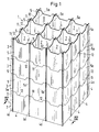
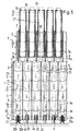
- the bearing arrangement according to Figure 1 contains one in one Storage pool usable storage rack 1 with one on the Bottom of the storage pool supportable lower Grating element 2 and more, on this attachable, stackable in layers Assembly units in the form of corresponding Grid elements 3, of which only in the drawing three are shown.
- Grid elements 2 and 3 are each arranged by crosswise, standing Sheet metal strips 4 and 4a or 5 and 5a formed, each made of a neutron absorbing material, e.g. one Boron alloy, and which vertical channels 7 to Inclusion of one fuel element 17 to be stored limit.
- the metal strips 4 and 4a or 5 and 5a each extend horizontally over one Row of several channels 7 and are by means of their Incisions 8 and 8a at the edges (Fig.
- the Grating elements 2 and 3 can each have one Part, e.g. half or a quarter of the cross section of the storage rack 1 or, as in the illustrated Example, across its entire cross-section.
- the incisions 8 and 8a each over half the height or Width of the metal strips 4 and 5 or 4a and 5a extend.
- the design described is a achieved secure plug connection, and the Grid elements 2 and 3 can each with essentially sub-pages or tops lying in one plane are carried out, whereby the grating elements 2 and 3 easily placed on top of each other and separated can be.
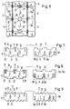
- the metal strips 5 and 5a are on their upper and lower edges, in addition to cuts 8 and 8a, depending on the type of toothing with their Longitudinally distributed, tooth-like Projections 11 and corresponding groove-like Recesses 12 carried out for merging with the corresponding depressions 12 or projections 11 of the plug-in plates 4, 4a and 5 and 5a of each in Setting direction of adjacent grating element 2 or 3 are determined.
- Fig.1 can the metal strips 4 and 4a of the lower Grid element 2 with flat, toothless lower Edges. Deviating from the shown Execution, the metal strips 5 and 5a of the top grating element 3 with toothless upper Edges.
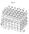
- the intermediate pieces 13 are shown as cubic coupling parts executed by which the Grid elements 2 and 3 each with the in the direction of installation adjacent grating element 3 or 2 form-fitting can be connected.
- the intermediate pieces 13 can also with not shown guide grooves for the respective recess 13 'delimiting sections of the Metal strips 4, 4a, 5 and 5a may be provided.
- Corresponding depressions 12 ' can also be between the intersecting metal strips 4 and 4a or 5 and 5a arranged and in any shape, e.g. rectangular, triangular, trapezoidal or, as in Fig. 6 shown to be semicircular.
- the Intermediate pieces 13 in any shape, 6 in the form of loose in the recesses 12 ' usable button-like coupling parts executed be, each one between two end plates 26 arranged, in the relevant recess 12 ' have insertable cylindrical guide shaft 27.
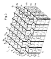
- channels 7 double-walled i.e. by two one each wall areas forming a flowable space a neutron absorbing material against the in Transverse direction adjacent channel 7 or against Shielded outside of the storage rack 1.
- the protrusions 11 and the Wells 12 can also be in any shape, e.g. 9 triangular according to Fig. 1 and 7 trapezoidal or, as shown in Figures 3 and 8, rectangular, with pointed or with rounded corners, be executed.
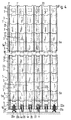
- the bearing arrangement according to Figure 4 contains a lower one Storage rack 1 corresponding to the version according to Fig. 1, with channels 7 for receiving dash-dotted lines shown fuel assemblies 17, and one on the Storage rack 1 attachable upper storage rack 1 'with the channels 7 of the storage rack 1 aligned channels 7 ' to accommodate at a second altitude fuel elements 17 'to be stored.
- the lower fuel assemblies 17 with their foot parts 18 via support pieces 20, 20a on the floor of the storage pool supported.
- Most supports, as shown the support pieces 20 are in one in the lower Grid element 2 trained, the channels 7th dividing support structure 21 vertically movable arranged and each with one over the support structure 21st protruding support part 22 executed.
- the support parts 22 are each with a vertical game S over the Support structure 21 positionable, which game S corresponding vertical relative movements between the Carrier pieces 20 and the support structure 21 allows.
- Suspension means 22a can be in the support structure 21 fixed threaded bushings are provided, in which the Support pieces 20a screwable and thus height adjustable and are held lockable.
- About the support pieces 20 and 20a can the weight of the fuel assemblies 17 without Load on the storage rack 1 on the bottom of the Storage basin are transferred.
- the storage rack 1 is an upper storage rack 1 'which can be fitted, like the lower storage rack 1, one above the other stackable, stackable and in described manner can be coupled to each other in a form-fitting manner Grid elements 3 assembled.
- the one from above upper fuel elements 17 'which can be inserted into the channels 7' can with their feet 18 over not shown Intermediate pieces or, as shown, directly on the Head portions 19 of the lower fuel assemblies supported which with positioning parts for the foot parts 18 can be provided. Accordingly, this can also be done Weight of the upper fuel assemblies 17 'without additional Load the lower storage rack 1 on the bottom of the Storage basin are transferred.
- Storage racks 1 and 1 ' can each be shown with several upright connecting parts 23 be carried out, each with at least the lower one Grid element 2 and the top grate element 3 of the storage rack 1 or with the lowest and the uppermost of the grating elements 3 of the storage rack 1 ' are firmly connected, creating a dimensionally stable Support structure of the relevant storage rack 1 or 1 ' is achievable.
- a version is also possible in which the lower Fuel elements 17 each with a side play in corresponding openings of the support structure 21 arranged and, independently of this, with their Foot sections 18 each directly on the floor of the Bearing base supported and with its head 19 over guide means, not shown, in each case Channel 7 are guided vertically movable.
- the lower grating element 2 in one particularly light construction.
- the upper Storage rack 1 ' also with respect to the channels 7 of lower storage rack 1 laterally Channels 7 'run that the top fuel assemblies 17 'each at the intersection of sheet metal strips 5 and 5a of the uppermost grating element 3 of the storage rack 1 can be supported.
- the lower grating element 2 is only executed by the weight of storage racks 1 and 1 'and the top Fuel elements 17 'loaded.
- the top are Fuel elements 17 'each in a surrounding shell 24 arranged a neutron absorbing material.
- the Sleeves 24 are each with the fuel assemblies 17 'in question firmly connected and shaped so that they with the Fuel elements 17 'each in one of the upper channels 17' Form an installation unit that can be inserted in the vertical direction.
- the upper storage rack 1 ' can also be used a height that is smaller than that Height of the lower storage rack 1 and therefore only a fraction of the length of the fuel assemblies 17 ' corresponds.
- the Grid elements 3 of the upper storage rack 1 ' also a weldable material and in essential as a guide arrangement for the through the Fuel elements 17 'and the shells 24 formed Installation units are designed.
- the grating elements 2, 3 can with any, even different height dimensions be carried out, which an adjustment of the height of the Storage rack 1 or 1 'to the length dimensions of the fuel elements 17 and 17 'to be stored in each case allow.
- Grid elements 2, 3 composed Storage rack body also on a separate, e.g. in shape one supported on the floor of the storage pool Base plate trained, the fuel assemblies Support structure arranged and / or with one on the top grating element 3, e.g. plate-shaped, upper support structure.
- an embodiment is also possible in which only one Number of sheet metal strips of each of the grating elements 2, 3, e.g. with double-walled design e.g. everyone second sheet metal strip, with depressions 12, 12 'and Projections 11 or spacers 13 are provided.
- a storage rack 1 that can be inserted into a storage pool contains several vertical channels 7 for receiving Fuel elements 17.
- the walls of the channels 7 are by themselves crossing sheet metal strips 4, 4a, 5, 5a from one neutron absorbing material formed, which in several, stackable in layers, dimensionally stable grating elements 2, 3 are arranged.
- the grating elements 2, 3 are each with several, to the upper and lower edges of their metal strips 4, 4a, 5, 5a formed groove-like depressions 12 and several, the corresponding wells 12 of the adjacent grating element 2 or 3 assigned Coupling parts 11 are provided, which are shaped such that with grating elements 2, 3 placed one on top of the other Coupling parts 11 and recesses 12 at least partially interlock positively. Accordingly, it can Storage rack 1 in a low work and Cost-effective, simple construction be carried out, which is a mechanization of assembly allowed and easy further expansion or allows a change in the bearing arrangement.
Landscapes
- Physics & Mathematics (AREA)
- Engineering & Computer Science (AREA)
- Plasma & Fusion (AREA)
- General Engineering & Computer Science (AREA)
- High Energy & Nuclear Physics (AREA)
- Stackable Containers (AREA)
- Battery Mounting, Suspending (AREA)
Description
Die Erfindung betrifft ein Lagergestell zum Lagern
nuklearer Brennelemente entsprechend dem Oberbegriff des
Patentanspruchs 1 sowie eine Lageranordnung mit einem
derartigen Lagergestell.The invention relates to a storage rack for storage
nuclear fuel elements according to the generic term of the
Bei einem aus der DE-OS 29 30 237 bekannten Lagergestell der genannten Art sind die zur Aufnahme der Brennelemente bestimmten vertikalen Kanäle durch übereinanderstehend angeordnete Blechstreifen gebildet, welche mit an ihren Rändern ausgebildeten Einschnitten versehen und über diese kreuzweise ineinandersteckbar und gegenseitig in ihrer Lage gehalten sind, wobei die sich kreuzenden Blechstreifen jeweils um deren halbe Breitenabmessung gegeneinander höhenversetzt angeordnet sind. Beim Zusammenbau des bekannten Lagergestells müssen die Blechstreifen einzeln eingesetzt werden, wobei jeweils eine untere Lage aus zueinander parallelen Blechstreifen erstellt und hierauf eine obere Lage aus quer zu den Blechstreifen der unteren Lage verlaufenden oberen Blechstreifen mit ihren Einschnitten in die Einschnitte der unteren Blechstreifen eingeführt wird. Das in jeweils zunehmender Bauhöhe von Hand erfolgende Ineinanderstecken der relativ langen und relativ dünnen Blechstreifen erfordert einen erheblichen Montageaufwand beim Zusammenbau des durch eine Vielzahl, z.B. mehreren hundert, Blechstreifen zu bildenden Lagergestells.In a storage rack known from DE-OS 29 30 237 of the type mentioned are those for receiving the fuel elements certain vertical channels by stacking arranged sheet metal strips formed, which with their Edges formed over and over these can be inserted into each other crosswise and mutually are held in their position, the intersecting Sheet strips each by half their width dimension are offset from each other in height. At the Assembly of the known storage rack must Sheet metal strips are used individually, each a lower layer of parallel metal strips created and then an upper layer from across the Sheet metal strips of the lower layer running upper Sheet metal strips with their incisions in the incisions the lower metal strip is inserted. That in each increasing overall height by hand the relatively long and relatively thin metal strips requires a considerable installation effort when Assembly of the by a variety, e.g. several hundred storage racks to be formed into sheet metal strips.
Der Erfindung liegt die Aufgabe zugrunde, ein mit geringerem Arbeits- und Kostenaufwand als bisher montierbares Lagergestell in einer gegenüber bisherigen Ausführungen vereinfachten Bauweise zu schaffen.The invention has for its object a less work and costs than before mountable storage rack in a compared to previous To create designs of simplified construction.
Diese Aufgabe wird erfindungsgemäss durch die
kennzeichnenden Merkmale des Patentanspruchs 1 gelöst.This object is achieved by the
characterizing features of
Die erfindungsgemässe Ausführung gestattet eine Mechanisierung der Montage und ermöglicht auf einfache Weise einen weiteren Ausbau bzw. eine Aenderung der Lageranordnung. Ein wesentlicher Vorteil besteht insbesondere darin, dass die mit hoher Genauigkeit und in grossen Serien herstellbaren Blechstreifen an einer speziell ausgerüsteten Montagestelle maschinell zusammengeführt, ineinandergesteckt und z.B. mittels einer Pressvorrichtung zu Gitterrostelementen vorgefertigt werden können. Die Gitterrostelemente können als weitgehend verwindungssteife Montageeinheiten übereinandergestapelt und auf einfache Weise, durch selbstzentrierendes Zusammenführen der Kupplungsteile mit den entsprechenden nutenartigen Vertiefungen des jeweils benachbarten Gitterrostelements miteinander verkuppelt werden. Entsprechend können die zur Aufnahme der Brennelemente bestimmten Kanäle des Lagergestells in wenigen, leicht ausführbaren Arbeitsgängen erstellt werden, wobei die ineinandergreifenden Kupplungsteile und Vertiefungen eine sichere gegenseitige Zentrierung und eine feste Positionierung der Gitterrostelemente gewährleisten. Ein weiterer Vorteil der erfindungsgemässen Ausführung besteht darin, dass die schichtweise angeordneten Blechstreifen jeweils entweder zu einteiligen, den ganzen Querschnitt des Lagergestells überdeckenden Montageeinheiten oder zu mehrteiligen, je einen Teil, z.B. die Hälfte oder ein Viertel, des Querschnitts des Lagergestells überdeckenden Montageeinheiten zusammengefasst sein können. Bei mehrteilig ausgebildeten Montageeinheiten kann jeweils der entsprechende Teil des Querschnitts des Lagergestells zugänglich gemacht und/oder für andere Zwecke, z.B. als Reserveabschnitt, bereitgestellt werden. Die Blechstreifen können in relativ grossen Serien hergestellt, zu beliebig grossen Gitterrostelementen zusammengefasst und in dieser leicht zu handhabenden Form für Wartungs- und Reparaturarbeiten und/oder für eine spätere Erweiterung der Lagerkapazität in Reserve gehalten werden.The embodiment according to the invention allows one Mechanization of assembly and allows for simple Way a further expansion or change of Bearing arrangement. There is a major advantage especially in that with high accuracy and in large series of producible sheet metal strips on one mechanically equipped assembly point merged, nested and e.g. by means of a pressing device for grating elements can be prefabricated. The grate elements can as largely torsionally rigid assembly units stacked on top of each other and in a simple way, through self-centering merging of the coupling parts with the corresponding groove-like depressions of each adjacent grating element coupled together become. Correspondingly, those for receiving the Fuel elements in certain channels of the storage rack few, easy to perform operations be, the interlocking coupling parts and Deepen a secure mutual centering and a fixed positioning of the grate elements guarantee. Another advantage of Execution according to the invention is that the layered sheet metal strips each either to one piece, the entire cross section of the storage rack covering assembly units or multi-part, each a part, e.g. half or a quarter of Cross-section of the storage rack covering Assembly units can be summarized. At Multi-part assembly units can each the corresponding part of the cross-section of the storage rack made accessible and / or for other purposes, e.g. as Reserve section. The Sheet metal strips can be made in relatively large series manufactured, to any size grating elements summarized and in this easy-to-use form for maintenance and repair work and / or for a later expansion of the storage capacity in reserve being held.
Ausgestaltungen des Erfindungsgegenstandes sind in den abhängigen Ansprüchen angegeben.Embodiments of the subject matter of the invention are in the dependent claims specified.
Gemäss Anspruch 2 kann auf einfache Weise, mit gegenüber
bisherigen Ausführungen wesentlich verringertem
Herstellungs- und Montageaufwand, aus entsprechend lose
aufeinander stapelbaren Gitterrostelementen ein
Lagergestell in doppelwandiger Ausführung zusammengebaut
werden, bei der die Wände der Kanäle je durch einen
Zwischenraum von der Wand des benachbarten Kanals
getrennt sind. Entsprechend kann die
neutronenabsorbierende Wirkung der Kanalwände erhöht bzw.
eine vorbestimmte Wirkung durch Verwendung von geringer
legiertem und damit kostengünstigerem Material erzielt
sowie eine verbesserte Kühlung der Kanalwände
gewährleistet werden. According to
Die Ausführung nach Anspruch 3 ergibt ein Lagergestell
aus besonders einfach zu handhabenden
Gitterrostelementen, welche insbesondere ohne zusätzliche
Verbindungsmittel miteinander koppelbar sind.The embodiment according to
Gemäss Anspruch 4 kann das Lagergestell auch aus einfacher ausgeführten Gitterrostelementen zusammengesetzt sein, welche je durch entsprechend einfach geformte Blechstreifen gebildet sind und welche miteinander über die zwischen die Blechstreifen lose einsetzbaren Kupplungsteile verbindbar sind.According to claim 4, the storage rack can also simple grating elements be composed, each by corresponding simply formed sheet metal strips are formed and which with each other over the loose between the metal strips usable coupling parts are connectable.
Die Ausführung nach Anspruch 5 ergibt eine in sich
formstabile Tragstruktur des Lagergestells.The embodiment according to
Eine Lageranordnung mit mindestens einem erfindungsgemässen Lagergestell ist Gegenstand des Anspruchs 6.A bearing arrangement with at least one Storage rack according to the invention is the subject of Claim 6.
Die Lageranordnung nach Anspruch 7 gestattet auf einfache
Weise eine Aufstockung des Lagergestells und damit eine
entsprechende Vergrösserung, gegebenenfalls eine
Verdoppelung, der Lagerkapazität.The bearing arrangement according to
Gemäss Anspruch 8 kann das obere Lagergestell mit dem
unteren Lagergestell auf einfache Weise über die an den
betreffenden Gitterrostelementen ausgebildeten Vorsprünge
und Vertiefungen fest verkoppelt werden.According to
Gemäss Anspruch 9 können die in der zweiten Höhenlage angeordneten Brennelemente je auf einem der bereits im unteren Lagergestell befindlichen Brennelemente, und damit ohne zusätzliche Belastung des unteren Lagergestells, abgestützt werden. According to claim 9 can in the second altitude arranged fuel assemblies each on one of the already fuel assembly located in the lower storage rack, and thus without additional strain on the lower one Storage rack are supported.
Gemäss Anspruch 10 können die in der zweiten Höhenlage angeordneten Brennelemente auch über die Kreuzungsstellen der Blechstreifen des obersten Gitterrostelementes des unteren Lagergestells auf diesem abgestützt werden.According to claim 10 can in the second altitude arranged fuel assemblies also over the crossing points the metal strip of the top grate element of the lower storage rack are supported on this.
Gemäss Anspruch 11 kann das obere Lagergestell mit einer
Bauhöhe ausgeführt werden, die nur einem Bruchteil der
Länge der in der zweiten Höhenlage einzulagernden
Brennelemente entspricht, so dass die Lageranordnung mit
einer gesamten Bauhöhe ausgeführt werden kann, die
wesentlich kleiner ist als die doppelte Länge der zu
lagernden Brennelemente.According to
Die Erfindung wird anhand von in der Zeichnung schematisch dargestellten Ausführungsbeispielen erläutert. Es zeigen:
- Fig.1
- ein erfindungsgemäss ausgebildetes Lagergestell einer Lageranordnung für nukleare Brennelemente in einer perspektivischen Teilansicht,
- Fig.2 u. 3
- weitere Lagergestelle, je in einer abgewandelten Ausführungsform und je in einer auseinandergezogenen perspektivischen Teilansicht,
- Fig.4
- eine erfindungsgemäss ausgebildete Lageranordnung in einer abgewandelten Ausführungsform, mit einem unteren Lagergestell und einem auf dieses aufsetzbaren oberen Lagergestell, in einem auseinandergezogenen Teillängsschnitt entsprechend der Linie IV - IV in Fig.1,
- Fig.5
- eine weitere Lageranordnung nach einer abgewandelten Ausführungsform, in einem Teillängsschnitt entsprechend der Darstellung nach Fig.4,
- Fig.6
- eine Einzelheit eines Lagergestells in einer gegenüber der Ausführung nach Fig.2 abgewandelten Ausführungsform, in einem Teillängsschnitt entsprechend der Linie VI - VI in Fig.2,
- Fig.7, 8 u. 9
- weitere Einzelheiten von Lagergestellen, je nach einer abgewandelten Ausführungsform.
- Fig. 1
- 2 shows a perspective view of a storage rack of a storage arrangement for nuclear fuel elements,
- Fig. 2 u. 3rd
- further storage racks, each in a modified embodiment and each in an exploded partial perspective view,
- Fig. 4
- 2 shows a bearing arrangement designed according to the invention in a modified embodiment, with a lower storage rack and an upper storage rack which can be placed thereon, in an exploded partial longitudinal section according to line IV-IV in FIG. 1,
- Fig. 5
- another bearing arrangement according to a modified embodiment, in a partial longitudinal section corresponding to the representation of Figure 4,
- Fig. 6
- 2 shows a detail of a storage rack in an embodiment modified from the embodiment according to FIG. 2, in a partial longitudinal section along the line VI-VI in FIG. 2,
- Fig. 7, 8 u. 9
- further details of storage racks, depending on a modified embodiment.
Die Lageranordnung nach Fig.1 enthält ein in ein
Lagerbecken einsetzbares Lagergestell 1 mit einem auf dem
Boden des Lagerbeckens abstützbaren unteren
Gitterrostelement 2 und mehreren, auf dieses
aufsetzbaren, schichtweise übereinander stapelbaren
Montageeinheiten in Form von entsprechenden
Gitterrostelementen 3, von denen in der Zeichnung nur
drei dargestellt sind. Die Gitterrostelemente 2 und 3
sind je durch kreuzweise angeordnete, stehende
Blechstreifen 4 und 4a bzw. 5 und 5a gebildet, welche je
aus einem neutronenabsorbierenden Werkstoff, z.B. einer
Borlegierung, bestehen und welche vertikale Kanäle 7 zur
Aufnahme je eines zu lagernden Brennelements 17
begrenzen. Die Blechstreifen 4 und 4a bzw. 5 und 5a
erstrecken sich je in waagrechter Richtung über eine
Reihe von mehreren Kanälen 7 und sind mittels an ihren
Rändern angebrachten Einschnitten 8 und 8a (Fig.7)
ineinandersteckbar ausgeführt und durch diese
Steckverbindung gegenseitig in ihrer Lage gehalten und zu
einem verwindungssteifen Einbauteil verbunden. Die
Gitterrostelemente 2 und 3 können sich je über einen
Teil, z.B. die Hälfte oder ein Viertel, des Querschnitts
des Lagergestells 1 oder, wie beim dargestellten
Beispiel, über dessen ganzen Querschnitt erstrecken. The bearing arrangement according to Figure 1 contains one in one
Storage pool
Wie insbesondere aus der Fig.7 hervorgeht, können sich
die Einschnitte 8 und 8a je über die halbe Höhe bzw.
Breite der Blechstreifen 4 und 5 bzw. 4a und 5a
erstrecken. Durch die beschriebene Ausführung wird eine
sichere Steckverbindung erzielt, und die
Gitterrostelemente 2 und 3 können mit je im wesentlichen
in einer Ebene liegenden Unterseiten bzw. Oberseiten
ausgeführt werden, wodurch die Gitterrostelemente 2 und 3
leicht aufeinander aufgesetzt und voneinander getrennt
werden können.As can be seen in particular from FIG
the
Die Blechstreifen 5 und 5a sind an ihren oberen und
unteren Rändern, zusätzlich zu den Einschnitten 8 und 8a,
je nach Art einer Verzahnung mit über ihre
Längserstreckung verteilt angeordneten, zahnartigen
Vorsprüngen 11 und entsprechenden nutenartigen
Vertiefungen 12 ausgeführt, die zum Zusammenführen mit
den entsprechenden Vertiefungen 12 bzw. Vorsprüngen 11
der Steckbleche 4, 4a sowie 5 und 5a des jeweils in
Aufsetzrichtung benachbarten Gitterrostelementes 2 bzw. 3
bestimmt sind. Entsprechend der Darstellung nach Fig.1
können die Blechstreifen 4 und 4a des unteren
Gitterrostelements 2 mit ebenen, unverzahnten unteren
Rändern ausgeführt sein. Abweichend von der dargestellten
Ausführung, können die Blechstreifen 5 und 5a des
obersten Gitterrostelements 3 mit unverzahnten oberen
Rändern ausgeführt sein.The
In der Zeichnung sind einander entsprechende Teile mit
gleichen Bezugszeichen versehen. Beim Lagergestell nach
Fig.2 sind die Blechstreifen 4, 4a und 5 und 5a mit
Vertiefungen 12' ausgeführt, welche je in Aufsetzrichtung
fluchtend zu den in den entsprechenden, am benachbarten
Blechstreifen 5, 5a bzw. 4, 4a ausgebildeten Vertiefungen
12' angeordnet sind und welche je zur Aufnahme eines in
die betreffende Vertiefung 12' des einen Blechstreifens
4, 4a bzw. 5, 5a einsetzbar und mit der in
Aufsetzrichtung benachbarten Vertiefung 12' des
benachbarten Blechstreifens 5, 5a bzw. 4, 4a
zusammenführbaren, separaten Zwischenstücks 13 bestimmt
sind. Die Vertiefungen 12' sind darstellungsgemäss je im
Bereich der Kreuzungsstellen der Blechstreifen 4 und 4a
bzw. 5 und 5a angeordnet und rechteckförmig ausgeführt.
Die Zwischenstücke 13 sind darstellungsgemäss als
kubische Kupplungsteile ausgeführt, durch welche die
Gitterrostelemente 2 und 3 je mit dem in Aufsetzrichtung
benachbarten Gitterrostelement 3 bzw. 2 formschlüssig
verbunden werden können. Die Zwischenstücke 13 können
auch mit nicht dargestellten Führungsnuten für die die
jeweilige Vertiefung 13' begrenzenden Abschnitte der
Blechstreifen 4, 4a, 5 und 5a versehen sein.Corresponding parts are shown in the drawing
provided with the same reference numerals. With the storage rack after
2 are the
Entsprechende Vertiefungen 12' können auch zwischen den
sich kreuzenden Blechstreifen 4 und 4a bzw. 5 und 5a
angeordnet und in beliebigen Formen, z.B. rechteckförmig,
dreieckförmig, trapezförmig oder, wie in Fig.6
dargestellt, halbrund ausgeführt sein. Ebenso können die
Zwischenstücke 13 in entsprechend beliebigen Formen,
gemäss Fig.6 in Form von lose in die Vertiefungen 12'
einsetzbaren knopfartigen Kupplungsteilen ausgeführt
sein, welche je einen zwischen zwei Endplatten 26
angeordneten, in die betreffende Vertiefung 12'
einführbaren zylindrischen Führungsschaft 27 aufweisen.Corresponding depressions 12 'can also be between the
intersecting
Beim Lagergestell nach Fig.3 sind die Kanäle 7
doppelwandig ausgeführt, d.h. durch je zwei einen
durchströmbaren Zwischenraum bildende Wandpartien aus
einem neutronenabsorbierenden Material gegen den in
Querrichtung benachbarten Kanal 7 bzw. gegen die
Aussenseite des Lagergestells 1 abgeschirmt. Dabei sind
die je einen Wandabschnitt einer Reihe der Kanäle 7
bildenden Blechstreifen 4 und 4a bzw. 5 und 5a je in
einem entsprechenden Abstand A von einem einen
Wandabschnitt der jeweils benachbarten Reihe der Kanäle 7
bildenden zweiten Blechstreifen 4, 4a, 5, 5a bzw. von
einem einen Teil der Aussenwand des Lagergestells
bildenden Randblechstreifen 14, 14a und 15, 15a
angeordnet.3 are the
Entsprechend der Darstellung nach Fig.8 sind die
Blechstreifen 5 und 15 sowie die nicht näher
dargestellten Blechstreifen 4 und 14 je mit über die
eine, darstellungsgemäss obere Hälfte verlaufenden
doppelten Einschnitten 8 versehen, während die
Blechstreifen 5a und 15a sowie 4a und 14a je mit über die
andere, untere Hälfte angeordneten doppelten Einschnitten
8a ausgeführt sind, die jeweils ein Ineinanderstecken der
die doppelwandige Gitterrostkonstruktion bildenden
Blechstreifen ermöglicht. Die Vorsprünge 11 und die
Vertiefungen 12 können ebenfalls in beliebigen Formen,
z.B. gemäss Fig.9 dreieckförmig, gemäss Fig.1 und 7
trapezförmig oder, wie in den Fig.3 und 8 dargestellt,
rechteckförmig, mit spitzen oder mit abgerundeten Ecken,
ausgeführt sein. Es versteht sich, dass auch beim
Lagergestell nach Fig.3 mit doppelwandig ausgeführten
Kanälen 7 die Gitterrostelemente 2 und 3 an den
aufeinander aufsetzbaren Rändern ihrer Blechstreifen 4,
5, 14, 15 bzw. 4a, 5a, 14a und 15a mit in Aufsetzrichtung
fluchtenden Vertiefungen 12' ausgeführt und durch in
diese lose einsetzbare Kupplungsteile in Form von
separaten Zwischenstücken je mit dem benachbarten
Gitterrostelement 3 bzw. 2 formschlüssig gekoppelt werden
können.According to the representation according to Figure 8, the
Die Lageranordnung nach Fig.4 enthält ein unteres
Lagergestell 1 entsprechend der Ausführung nach Fig.1,
mit Kanälen 7 zur Aufnahme von strichpunktiert
dargestellten Brennelementen 17, sowie ein auf das
Lagergestell 1 aufsetzbares oberes Lagergestell 1' mit zu
den Kanälen 7 des Lagergestells 1 fluchtenden Kanälen 7'
zur Aufnahme von in einer zweiten Höhenlage
einzulagernden Brennelementen 17'. Bei dieser Ausführung
sind die unteren Brennelemente 17 mit ihren Fusspartien
18 über Tragstücke 20, 20a auf dem Boden des Lagerbeckens
abgestützt. Die meisten Tragstücke, darstellungsgemäss
die Tragstücke 20, sind in einer im unteren
Gitterrostelement 2 ausgebildeten, die Kanäle 7
unterteilenden Stützkonstruktion 21 vertikal beweglich
angeordnet und je mit einem über die Stützkonstruktion 21
vorstehenden Stützteil 22 ausgeführt. Die Stützteile 22
sind je mit einem vertikalen Spiel S über der
Stützkonstruktion 21 positionierbar, welches Spiel S
entsprechend vertikale Relativbewegungen zwischen den
Tragstücken 20 und der Stützkonstruktion 21 zulässt. Eine
über den Querschnitt des Lagergestells 1 verteilt
angeordnete Teilzahl der Tragstücke, darstellungsgemäss
die Tragstücke 20a, sind mit der Stützkonstruktion 21
über Tragmittel 22a gekoppelt, über welche das untere
Gitterrostelement 2 und damit das ganze Lagergestell 1
auf diesen Tragstücken 20a abgestützt sind. Als
Tragmittel 22a können in der Stützkonstruktion 21
befestigte Gewindebüchsen vorgesehen sein, in denen die
Tragstücke 20a einschraubbar und damit höhenverstellbar
und feststellbar gehalten sind. Ueber die Tragstücke 20
und 20a kann das Gewicht der Brennelemente 17 ohne
Belastung des Lagergestells 1 auf den Boden des
Lagerbeckens übertragen werden.The bearing arrangement according to Figure 4 contains a lower one
Das in Fig.4 in abgehobener Stellung dargestellte, auf
das Lagergestell 1 aufsetzbare obere Lagergestell 1' ist,
wie das untere Lagergestell 1, aus übereinander
stapelbaren, aufeinander aufsetzbaren und in
beschriebener Weise miteinander formschlüssig kuppelbaren
Gitterrostelementen 3 zusammengesetzt. Die von oben her
in die Kanäle 7' einführbaren oberen Brennelemente 17'
können mit ihren Fusspartien 18 über nicht dargestellte
Zwischenstücke oder, wie dargestellt, unmittelbar auf den
Kopfpartien 19 der unteren Brennelemente abgestützt
werden, welche mit Positionierteilen für die Fusspartien
18 versehen sein können. Entsprechend kann auch das
Gewicht der oberen Brennelemente 17' ohne zusätzliche
Belastung des unteren Lagergestells 1 auf den Boden des
Lagerbeckens übertragen werden.The shown in Figure 4 in the raised position
the
Die Lagergestelle 1 und 1' können darstellungsgemäss je
mit mehreren aufrecht angeordneten Verbindungsteilen 23
ausgeführt sein, welche je zumindest mit dem unteren
Gitterrostelement 2 und dem obersten Gitterrostelement 3
des Lagergestells 1 bzw. mit dem untersten und dem
obersten der Gitterrostelemente 3 des Lagergestells 1'
fest verbunden sind, wodurch jeweils eine formstabile
Tragkonstruktion des betreffenden Lagergestells 1 bzw. 1'
erzielbar ist.
Es ist auch eine Ausführung möglich, bei der die unteren
Brennelemente 17 je mit einem seitlichen Spiel in
entsprechenden Oeffnungen der Stützkonstruktion 21
angeordnet und, von dieser unabhängig, mit ihren
Fusspartien 18 je unmittelbar auf dem Boden des
Lagerbodens abgestützt und mit ihren Kopfpartien 19 über
nicht dargestellte Führungsmittel je im betreffenden
Kanal 7 vertikal beweglich geführt sind. Bei dieser
Ausführung kann das untere Gitterrostelement 2 in einer
besonders leichten Bauweise ausgeführt werden.A version is also possible in which the
Entsprechend der Darstellung nach Fig.5 kann das obere
Lagergestell 1' auch mit gegenüber den Kanälen 7 des
unteren Lagergestells 1 seitlich so weit versetzten
Kanälen 7' ausgeführt sein, dass die oberen Brennelemente
17' je auf den Kreuzungsstellen der Blechstreifen 5 und
5a des obersten Gitterrostelements 3 des Lagergestells 1
abgestützt werden können. Entsprechend wird das Gewicht
der oberen Brennelemente 17' über die Wände der Kanäle 7
auf das vom Gewicht der unteren Brennelemente 17
entlastete untere Gitterrostelement 2 und über dieses auf
den Boden des Lagerbeckens übertragen. Bei dieser
Ausführung wird das untere Gitterrostelement 2 nur durch
das Gewicht der Lagergestelle 1 und 1' und der oberen
Brennelemente 17' belastet.According to the representation of Figure 5, the upper
Storage rack 1 'also with respect to the
Wie aus der Fig.5 weiter hervorgeht, sind die oberen
Brennelemente 17' je in einer sie umgebenden Hülle 24 aus
einem neutronenabsorbierenden Werkstoff angeordnet. Die
Hüllen 24 sind je mit den betreffenden Brennelementen 17'
fest verbunden und so geformt, dass sie mit den
Brennelementen 17' je eine in einen der oberen Kanäle 17'
in vertikaler Richtung einführbare Einbaueinheit bilden.
Darstellungsgemäss kann das obere Lagergestell 1' mit
einer Bauhöhe ausgeführt sein, welche kleiner ist als die
Bauhöhe des unteren Lagergestells 1 und welche daher nur
einem Bruchteil der Länge der Brennelemente 17'
entspricht. Bei dieser Ausführung können die
Gitterrostelemente 3 des oberen Lagergestells 1' auch aus
einem schweissbaren Werkstoff bestehen und im
wesentlichen als Führungsanordnung für die durch die
Brennelemente 17' und die Hüllen 24 gebildeten
Einbaueinheiten ausgebildet sein.As can be seen from Fig.5, the top are
Fuel elements 17 'each in a surrounding
Es sind zahlreiche abgewandelte Ausführungsformen der
Erfindung möglich. Die Gitterrostelemente 2, 3 können mit
beliebigen, auch unterschiedlichen Höhenabmessungen
ausgeführt sein, welche eine Anpassung der Bauhöhe des
Lagergestells 1 bzw. 1' an die Längenabmessungen der
jeweils einzulagernden Brennelemente 17 bzw. 17'
gestatten. Ein aus vorstehend beschriebenen
Gitterrostelementen 2, 3 zusammengesetzter
Lagergestellkörper auch auf einer separaten, z.B. in Form
einer auf dem Boden des Lagerbeckens abgestützten
Grundplatte ausgebildeten, die Brennelemente tragenden
Stützkonstruktion angeordnet und/oder mit einer auf das
oberste Gitterrostelement 3 aufsetzbaren, z.B.
plattenförmigen, oberen Haltekonstruktion verbunden sein.
Ferner ist auch eine Ausführung möglich, bei der nur eine
Teilzahl der Blechstreifen jedes der Gitterrostelemente
2, 3, z.B. bei doppelwandiger Ausführung z.B. jeder
zweite Blechstreifen, mit Vertiefungen 12, 12' und
Vorsprüngen 11 bzw. Zwischenstücken 13 versehen sind.There are numerous modified embodiments of the
Invention possible. The
Zusammenfassend lässt sich die Erfindung wie folgt beschreiben:In summary, the invention can be summarized as follows describe:
Ein in ein Lagerbecken einsetzbares Lagergestell 1
enthält mehrere vertikale Kanäle 7 zur Aufnahme von
Brennelementen 17. Die Wände der Kanäle 7 sind durch sich
kreuzende Blechstreifen 4, 4a, 5, 5a aus einem
neutronenabsorbierenden Werkstoff gebildet, welche in
mehreren, schichtweise übereinander stapelbaren,
formstabilen Gitterrostelementen 2, 3 angeordnet sind.
Die Gitterrostelemente 2, 3 sind je mit mehreren, an den
oberen und unteren Rändern ihrer Blechstreifen 4, 4a, 5,
5a ausgebildeten nutenartigen Vertiefungen 12 und mit
mehreren, den entsprechenden Vertiefungen 12 des
benachbarten Gitterrostelements 2 bzw. 3 zugeordneten
Kupplungsteilen 11 versehen, welche so geformt sind, dass
bei aufeinander aufgesetzten Gitterrostelementen 2, 3 die
Kupplungsteile 11 und Vertiefungen 12 zumindest teilweise
formschlüssig ineinandergreifen. Entsprechend kann das
Lagergestell 1 in einer mit geringem Arbeits- und
Kostenaufwand realisierbaren, einfachen Bauweise
ausgeführt werden, welche eine Mechanisierung der Montage
gestattet und auf einfache Weise einen weiteren Ausbau
bzw. eine Aenderung der Lageranordnung ermöglicht.A
Claims (11)
- Storage framework for the storage of nuclear fuel elements (17, 17') with a plurality of vertical channels (7, 7') arranged next to one another for the purpose of receiving the fuel elements (17, 17'), with the walls of the channels being made of sheet metal strips (4, 4a, 5, 5a) formed of a neutron absorbing material placed one above the other and crossing one another characterised in that the sheet metal strips (4, 4a, 5, 5a) are arranged in a plurality of assembly units which can be placed layer-wise one upon another and are separable from one another and are united in these assembly units to a respective form-stable grid element (2, 3); and in that the grid elements (2, 3) are each provided with a plurality of groove-like recesses (12, 12'), formed at least in some of the sheet metal strips (4, 4a, 5, 5a) at their upper and lower edges, and are provided with a plurality of coupling parts for the purpose of being inserted into the corresponding recesses (12, 12') of the neighbouring grid elements (2 and/or 3), which are formed in such a manner that when the grid elements (2, 3) are placed one upon another the coupling parts and recesses (12, 12') at least partially engage one another in a form fitted manner.
- Storage framework in accordance with claim 1 with grid elements (2, 3) in which the sheet metal strips (4, 4a, 5, 5a) forming a respective wall section of a row of the channels (7, 7') are each arranged at a distance (A) from an additional sheet metal strip (4, 4a, 5, 5a, 14, 14a, 15, 15a) forming a wall section of a neighbouring row of the channels (7, 7') or an outer wall of the storage framework, with these additional sheet metal strips (4, 4a, 5, 5a, 14, 14a, 15, 15a) being likewise-executed with groove-like recesses (12, 12').
- Storage framework in accordance with claim 1 or 2 characterised in that the groove-like recesses (12) are bounded by tooth-like projections (11) distributed over the longitudinal extent of the sheet metal strips (4, 4a, 5, 5a, 14, 14a, 15, 15a), which are designed as coupling parts and formed such that when the grid elements (2, 3) are placed one upon the other the projections (11) and recesses (12) engage one another in the manner of meshed teeth.
- Storage framework in accordance with claim 1 or 2 characterised in that the groove-like recesses (12') of the sheet metal strips (4, 4a, 5, 5a, 14, 14a, 15, 15a) are each arranged to be aligned in the direction of placement; and in that the coupling parts are each formed by a separate intermediate piece (13) which can be inserted into one of the recesses (12') and brought together with the neighbouring recess (12').
- Storage framework in accordance with one of the preceding claims characterised in that the grid elements (2, 3) placed one upon the other are arranged between a plurality of connection parts (23) placed upright, which are each firmly connected at least to the lowermost and to the uppermost of the grid elements (2, 3).
- Storage arrangement with at least one storage framework in accordance with one of the above claims.
- Storage arrangement in accordance with claim 6 characterised in that for the reception of upper fuel elements (17') to be stored at a second vertical level an upper storage framework (1') is provided which can be placed on the upper part of the one, lower storage framework (1) and which contains at least one grid element (3) executed corresponding to the grid elements (2, 3) of the lower storage framework 1) in which upper channels (7') corresponding to the channels (7) of the lower storage framework (1) are formed.
- Storage arrangement in accordance with claim 6 characterised in that the lowermost grid element (3) of the upper storage framework (1) is executed with groove-like recesses (12, 12') which are intended to be brought together with the corresponding coupling parts (11, 13) projecting from the uppermost grid element 3) of the lower storage framework (1).
- Storage arrangement in accordance with claim 7 or 8 characterised in that the channels (7') of the upper storage framework (1') are executed to be aligned with the channels (7') of the lower storage framework (1).
- Storage arrangement in accordance with claim 5 or 6 characterised in that the channels (7') of the upper storage framework (1') are executed to be displaced laterally with respect to the channels (7) of the lower storage framework 1).
- Storage arrangement in accordance with one of the claims 7 to 9 characterised in that the channels (7') of the upper storage framework (1') are each formed as a guidance channel for receiving a sheath (24) made of a neutron absorbing material connected to the upper fuel element (17') to be stored.
Priority Applications (4)
| Application Number | Priority Date | Filing Date | Title |
|---|---|---|---|
| DE59505388T DE59505388D1 (en) | 1995-10-18 | 1995-10-18 | Storage rack for storing nuclear fuel elements and storage arrangement with at least one such storage rack |
| EP95810649A EP0769785B1 (en) | 1995-10-18 | 1995-10-18 | Storage rack for storing nuclear fuel elements and storage facility with at least one such storage rack |
| ES95810649T ES2130557T3 (en) | 1995-10-18 | 1995-10-18 | SUPPORT FOR THE STORAGE OF NUCLEAR FUEL ELEMENTS AND STORAGE DEVICE THAT INCLUDES AT LEAST SUCH SUPPORT. |
| ZA968729A ZA968729B (en) | 1995-10-18 | 1996-10-16 | Storage framework for the storage of nuclear fuel elements and a storage arrangement with at least one such storage framework |
Applications Claiming Priority (1)
| Application Number | Priority Date | Filing Date | Title |
|---|---|---|---|
| EP95810649A EP0769785B1 (en) | 1995-10-18 | 1995-10-18 | Storage rack for storing nuclear fuel elements and storage facility with at least one such storage rack |
Publications (2)
| Publication Number | Publication Date |
|---|---|
| EP0769785A1 EP0769785A1 (en) | 1997-04-23 |
| EP0769785B1 true EP0769785B1 (en) | 1999-03-17 |
Family
ID=8221807
Family Applications (1)
| Application Number | Title | Priority Date | Filing Date |
|---|---|---|---|
| EP95810649A Expired - Lifetime EP0769785B1 (en) | 1995-10-18 | 1995-10-18 | Storage rack for storing nuclear fuel elements and storage facility with at least one such storage rack |
Country Status (4)
| Country | Link |
|---|---|
| EP (1) | EP0769785B1 (en) |
| DE (1) | DE59505388D1 (en) |
| ES (1) | ES2130557T3 (en) |
| ZA (1) | ZA968729B (en) |
Families Citing this family (2)
| Publication number | Priority date | Publication date | Assignee | Title |
|---|---|---|---|---|
| ES2205974B1 (en) * | 2001-05-24 | 2005-05-01 | Equipos Nucleares, S.A. | SEGMENTED FRAME OF INTERRELATED CELLULAR MATRIX, TO STORE FUELS FROM NUCLEAR REACTORS. |
| JP4621699B2 (en) * | 2007-02-13 | 2011-01-26 | 株式会社東芝 | Spent fuel storage rack |
Family Cites Families (4)
| Publication number | Priority date | Publication date | Assignee | Title |
|---|---|---|---|---|
| FR2462767A2 (en) * | 1978-08-12 | 1981-02-13 | Babcock Brown Boveri Reaktor | Nuclear fuel element storage frame - with freedom of motion for grid sheets relative to structure |
| DE2930237C2 (en) | 1979-07-26 | 1984-02-09 | Brown Boveri Reaktor GmbH, 6800 Mannheim | Frame for the vertical storage of elongated nuclear reactor fuel elements |
| DE2904362C2 (en) * | 1979-02-06 | 1982-04-15 | Brown Boveri Reaktor GmbH, 6800 Mannheim | Storage rack for nuclear reactor fuel elements |
| FR2680909B1 (en) * | 1991-09-04 | 1994-04-01 | Atea Ste Atlantique Tech Avancee | RACK FOR STORING OR TRANSPORTING NUCLEAR FUEL AND MANUFACTURING METHOD THEREOF. |
-
1995
- 1995-10-18 DE DE59505388T patent/DE59505388D1/en not_active Expired - Lifetime
- 1995-10-18 ES ES95810649T patent/ES2130557T3/en not_active Expired - Lifetime
- 1995-10-18 EP EP95810649A patent/EP0769785B1/en not_active Expired - Lifetime
-
1996
- 1996-10-16 ZA ZA968729A patent/ZA968729B/en unknown
Also Published As
| Publication number | Publication date |
|---|---|
| DE59505388D1 (en) | 1999-04-22 |
| ZA968729B (en) | 1997-05-21 |
| ES2130557T3 (en) | 1999-07-01 |
| EP0769785A1 (en) | 1997-04-23 |
Similar Documents
| Publication | Publication Date | Title |
|---|---|---|
| EP1899553B1 (en) | Ceiling formwork system | |
| EP0536571B1 (en) | Piling column for stacked material | |
| EP0054827A1 (en) | Fuel assembly for a boiling water nuclear reator | |
| DE3833875A1 (en) | GRID FOR DOUBLE FLOORS | |
| DE20107472U1 (en) | Support structure for general objects | |
| DE29724813U1 (en) | floor element | |
| EP0517117B1 (en) | Wooden plant container | |
| DE2835392A1 (en) | STORAGE RACK FOR CORE REACTOR FUEL ELEMENTS | |
| EP0769785B1 (en) | Storage rack for storing nuclear fuel elements and storage facility with at least one such storage rack | |
| CH681998A5 (en) | Wall element comprising body of artificial resin concrete - has fixture inserted in side surfaces with on one side surface projecting holder pins of metal | |
| DE2926780C2 (en) | Formwork panel | |
| EP0014422B1 (en) | Storage rack for nuclear reactor fuel elements | |
| DE8702930U1 (en) | Bottle crate | |
| DE2703582C2 (en) | Frame construction for ceramic products | |
| DE29620192U1 (en) | Component set consisting of at least three identical cab-shaped container elements | |
| EP0384023A1 (en) | Carrier board for roof turfings | |
| EP0273086B1 (en) | Building element kit and usage of the same | |
| DE3127080A1 (en) | Plantable display wall | |
| DE2755573C2 (en) | Base frame, especially for plansifters | |
| EP0106919B1 (en) | Composite setter for the firing in a kiln of ceramic tiles or other similar articles | |
| DE69207764T2 (en) | STORAGE RACK FOR COMBUSED CORE REACTOR FUEL ELEMENTS | |
| EP0759623B1 (en) | Storage installation for nuclear fuel assemblies and storage rack therefor | |
| DE9201219U1 (en) | Wine bottle rack | |
| EP0317937A1 (en) | Formwork system | |
| DE2540145B2 (en) | Spacers |
Legal Events
| Date | Code | Title | Description |
|---|---|---|---|
| PUAI | Public reference made under article 153(3) epc to a published international application that has entered the european phase |
Free format text: ORIGINAL CODE: 0009012 |
|
| AK | Designated contracting states |
Kind code of ref document: A1 Designated state(s): BE CH DE ES FR GB LI NL SE |
|
| AX | Request for extension of the european patent |
Free format text: LT;SI |
|
| RBV | Designated contracting states (corrected) |
Designated state(s): BE CH DE ES FR GB LI NL SE |
|
| 17P | Request for examination filed |
Effective date: 19970925 |
|
| GRAG | Despatch of communication of intention to grant |
Free format text: ORIGINAL CODE: EPIDOS AGRA |
|
| 17Q | First examination report despatched |
Effective date: 19980520 |
|
| GRAG | Despatch of communication of intention to grant |
Free format text: ORIGINAL CODE: EPIDOS AGRA |
|
| GRAH | Despatch of communication of intention to grant a patent |
Free format text: ORIGINAL CODE: EPIDOS IGRA |
|
| RAP1 | Party data changed (applicant data changed or rights of an application transferred) |
Owner name: CCI AG |
|
| GRAH | Despatch of communication of intention to grant a patent |
Free format text: ORIGINAL CODE: EPIDOS IGRA |
|
| GRAA | (expected) grant |
Free format text: ORIGINAL CODE: 0009210 |
|
| AK | Designated contracting states |
Kind code of ref document: B1 Designated state(s): BE CH DE ES FR GB LI NL SE |
|
| REG | Reference to a national code |
Ref country code: CH Ref legal event code: NV Representative=s name: SULZER MANAGEMENT AG Ref country code: CH Ref legal event code: EP |
|
| GBT | Gb: translation of ep patent filed (gb section 77(6)(a)/1977) |
Effective date: 19990319 |
|
| REF | Corresponds to: |
Ref document number: 59505388 Country of ref document: DE Date of ref document: 19990422 |
|
| REG | Reference to a national code |
Ref country code: ES Ref legal event code: FG2A Ref document number: 2130557 Country of ref document: ES Kind code of ref document: T3 |
|
| ET | Fr: translation filed | ||
| PLBE | No opposition filed within time limit |
Free format text: ORIGINAL CODE: 0009261 |
|
| STAA | Information on the status of an ep patent application or granted ep patent |
Free format text: STATUS: NO OPPOSITION FILED WITHIN TIME LIMIT |
|
| 26N | No opposition filed | ||
| REG | Reference to a national code |
Ref country code: GB Ref legal event code: IF02 |
|
| REG | Reference to a national code |
Ref country code: CH Ref legal event code: NV Representative=s name: INTELLECTUAL PROPERTY SERVICES GMBH, CH |
|
| PGFP | Annual fee paid to national office [announced via postgrant information from national office to epo] |
Ref country code: GB Payment date: 20141021 Year of fee payment: 20 Ref country code: DE Payment date: 20141022 Year of fee payment: 20 Ref country code: SE Payment date: 20141021 Year of fee payment: 20 Ref country code: ES Payment date: 20141028 Year of fee payment: 20 Ref country code: CH Payment date: 20141021 Year of fee payment: 20 Ref country code: FR Payment date: 20141022 Year of fee payment: 20 |
|
| PGFP | Annual fee paid to national office [announced via postgrant information from national office to epo] |
Ref country code: NL Payment date: 20141021 Year of fee payment: 20 |
|
| PGFP | Annual fee paid to national office [announced via postgrant information from national office to epo] |
Ref country code: BE Payment date: 20141021 Year of fee payment: 20 |
|
| REG | Reference to a national code |
Ref country code: DE Ref legal event code: R071 Ref document number: 59505388 Country of ref document: DE |
|
| REG | Reference to a national code |
Ref country code: NL Ref legal event code: MK Effective date: 20151017 |
|
| REG | Reference to a national code |
Ref country code: CH Ref legal event code: PL |
|
| REG | Reference to a national code |
Ref country code: GB Ref legal event code: PE20 Expiry date: 20151017 |
|
| REG | Reference to a national code |
Ref country code: SE Ref legal event code: EUG |
|
| REG | Reference to a national code |
Ref country code: ES Ref legal event code: FD2A Effective date: 20160126 |
|
| PG25 | Lapsed in a contracting state [announced via postgrant information from national office to epo] |
Ref country code: GB Free format text: LAPSE BECAUSE OF EXPIRATION OF PROTECTION Effective date: 20151017 |
|
| PG25 | Lapsed in a contracting state [announced via postgrant information from national office to epo] |
Ref country code: ES Free format text: LAPSE BECAUSE OF EXPIRATION OF PROTECTION Effective date: 20151019 |