EP0769462B1 - Verfahren und Vorrichtung zum gleichmässigen Verteilen von Feststoffen in fein verteilter Form, in einem Behälter - Google Patents
Verfahren und Vorrichtung zum gleichmässigen Verteilen von Feststoffen in fein verteilter Form, in einem Behälter Download PDFInfo
- Publication number
- EP0769462B1 EP0769462B1 EP96402138A EP96402138A EP0769462B1 EP 0769462 B1 EP0769462 B1 EP 0769462B1 EP 96402138 A EP96402138 A EP 96402138A EP 96402138 A EP96402138 A EP 96402138A EP 0769462 B1 EP0769462 B1 EP 0769462B1
- Authority
- EP
- European Patent Office
- Prior art keywords
- deflector elements
- solid
- vessel
- rotation
- level
- Prior art date
- Legal status (The legal status is an assumption and is not a legal conclusion. Google has not performed a legal analysis and makes no representation as to the accuracy of the status listed.)
- Expired - Lifetime
Links
- 238000000034 method Methods 0.000 title claims abstract description 22
- 239000007787 solid Substances 0.000 title claims abstract description 21
- 230000008569 process Effects 0.000 claims abstract description 10
- 230000000694 effects Effects 0.000 claims description 7
- 238000011068 loading method Methods 0.000 abstract description 25
- 238000009827 uniform distribution Methods 0.000 abstract description 5
- 239000003054 catalyst Substances 0.000 description 16
- 239000002245 particle Substances 0.000 description 9
- 230000035699 permeability Effects 0.000 description 7
- 238000010586 diagram Methods 0.000 description 6
- 239000000126 substance Substances 0.000 description 4
- 230000008901 benefit Effects 0.000 description 3
- 230000003197 catalytic effect Effects 0.000 description 3
- 230000008859 change Effects 0.000 description 3
- 238000009826 distribution Methods 0.000 description 3
- 238000006243 chemical reaction Methods 0.000 description 2
- 230000000052 comparative effect Effects 0.000 description 2
- 229930195733 hydrocarbon Natural products 0.000 description 2
- 150000002430 hydrocarbons Chemical class 0.000 description 2
- 230000004048 modification Effects 0.000 description 2
- 238000012986 modification Methods 0.000 description 2
- 238000003860 storage Methods 0.000 description 2
- 239000011800 void material Substances 0.000 description 2
- 239000011324 bead Substances 0.000 description 1
- 230000015556 catabolic process Effects 0.000 description 1
- 238000005336 cracking Methods 0.000 description 1
- 230000007423 decrease Effects 0.000 description 1
- 238000006477 desulfuration reaction Methods 0.000 description 1
- 230000023556 desulfurization Effects 0.000 description 1
- 229940082150 encore Drugs 0.000 description 1
- VJYFKVYYMZPMAB-UHFFFAOYSA-N ethoprophos Chemical compound CCCSP(=O)(OCC)SCCC VJYFKVYYMZPMAB-UHFFFAOYSA-N 0.000 description 1
- 239000007789 gas Substances 0.000 description 1
- 238000009434 installation Methods 0.000 description 1
- 239000007788 liquid Substances 0.000 description 1
- 239000007937 lozenge Substances 0.000 description 1
- 238000004519 manufacturing process Methods 0.000 description 1
- 238000005259 measurement Methods 0.000 description 1
- 230000008520 organization Effects 0.000 description 1
- 239000003208 petroleum Substances 0.000 description 1
- 230000001737 promoting effect Effects 0.000 description 1
- 238000003908 quality control method Methods 0.000 description 1
- 238000002407 reforming Methods 0.000 description 1
Images

Classifications
-
- B—PERFORMING OPERATIONS; TRANSPORTING
- B65—CONVEYING; PACKING; STORING; HANDLING THIN OR FILAMENTARY MATERIAL
- B65G—TRANSPORT OR STORAGE DEVICES, e.g. CONVEYORS FOR LOADING OR TIPPING, SHOP CONVEYOR SYSTEMS OR PNEUMATIC TUBE CONVEYORS
- B65G69/00—Auxiliary measures taken, or devices used, in connection with loading or unloading
- B65G69/04—Spreading out the materials conveyed over the whole surface to be loaded; Trimming heaps of loose materials
- B65G69/0458—Spreading out the materials conveyed over the whole surface to be loaded; Trimming heaps of loose materials with rotating means, e.g. tables, arms
-
- B—PERFORMING OPERATIONS; TRANSPORTING
- B01—PHYSICAL OR CHEMICAL PROCESSES OR APPARATUS IN GENERAL
- B01J—CHEMICAL OR PHYSICAL PROCESSES, e.g. CATALYSIS OR COLLOID CHEMISTRY; THEIR RELEVANT APPARATUS
- B01J8/00—Chemical or physical processes in general, conducted in the presence of fluids and solid particles; Apparatus for such processes
- B01J8/0015—Feeding of the particles in the reactor; Evacuation of the particles out of the reactor
- B01J8/002—Feeding of the particles in the reactor; Evacuation of the particles out of the reactor with a moving instrument
-
- B—PERFORMING OPERATIONS; TRANSPORTING
- B01—PHYSICAL OR CHEMICAL PROCESSES OR APPARATUS IN GENERAL
- B01J—CHEMICAL OR PHYSICAL PROCESSES, e.g. CATALYSIS OR COLLOID CHEMISTRY; THEIR RELEVANT APPARATUS
- B01J2208/00—Processes carried out in the presence of solid particles; Reactors therefor
- B01J2208/00743—Feeding or discharging of solids
- B01J2208/00752—Feeding
-
- B—PERFORMING OPERATIONS; TRANSPORTING
- B01—PHYSICAL OR CHEMICAL PROCESSES OR APPARATUS IN GENERAL
- B01J—CHEMICAL OR PHYSICAL PROCESSES, e.g. CATALYSIS OR COLLOID CHEMISTRY; THEIR RELEVANT APPARATUS
- B01J2208/00—Processes carried out in the presence of solid particles; Reactors therefor
- B01J2208/00743—Feeding or discharging of solids
- B01J2208/00769—Details of feeding or discharging
- B01J2208/00778—Kinetic energy reducing devices in the flow channel
Definitions
- the present invention relates to a method and a device for the uniform distribution of a solid under divided form in an enclosure. It concerns more particularly filling silos with grain, or chemical reactors with a catalyst in the form divided.
- solid in divided form is meant a solid in the form of balls, grains, cylinders, lozenges, sticks or, more generally, particles of any shape, but of dimensions relatively weak.
- the catalysts used in the chemical transformation reactions or hydrocarbons for example reforming, cracking, desulfurization of hydrocarbons or petroleum fractions, hydrotreatment processes in general, arise in the form of beads, extrudates or multi-lobe elements small dimensions.
- the Applicant has itself proposed methods of dense load using moving equipment, which includes a shaft driven in rotation by a motor means and several stages of flexible deflector elements such as straps (see EP-A-007,854 and EP-A-116,246).
- Such devices do not allow loading continuous reactor with a uniform filling profile. Indeed, as will be seen in more detail below, it is necessary to change the rotation speed of the crew mobile when the enclosure fills. These modifications pose major technical problems for operators because it is very difficult to predict the effect of these speed changes on the quality of the load. A very small change in rotation speed can disturb the rain effect, i.e. the amount of particles deflected by the moving part.
- the object of the present invention is to limit these significant disadvantages.
- the Applicant has, in fact, established that the relative positions of the straps or, more generally, deflector elements articulated to different levels of the motor shaft and driven in rotation by it, are of importance essential.
- This crew is disposed either, as in the technique anterior, so as to distribute the strips of uniformly different levels of the crew to cover a maximum of the surface presented to the grains and therefore obtain a minimum crew void rate rotating, but on the contrary with the deflector elements of each level arranged directly above each other, not offset from each other as in the prior art, so as to give all of the moving crew a higher vacuum rate than that obtained with the arrangement of the deflector elements adopted in the prior art.
- rate of empty of the moving part we mean the ratio (in%) of the surface not covered by the deflectors on the total surface of the moving crew, once the elements deflectors deployed in the enclosure.
- This new organization of the deflectors of the moving part which gives the latter a vacuum rate between 30% and 80%, depending on the dimensions of generally used straps, has the effect that, so completely surprising, the filling of a reactor, with the process according to the present invention allows to obtain a dense loading similar to the prior art of the Applicant, with, in addition, a better quality of this loading and horizontal preferential orientation of grains of catalyst, thus improving the contacts between the catalyst, liquids or gases.
- the arrangement of the deflectors adopted according to the invention allows, while promoting the control of the permeability of the moving part, better control machine parameters, thereby reducing the number of interventions for checks and adjustments and reducing the loading time accordingly.
- grain permeability is meant the amount (in%) of grains of catalyst passing through the crew mobile in rotation, without being deflected by an impact on a strap.
- the present invention therefore relates to a method of uniform distribution of a solid in divided form in an enclosure, in which the solid falls on a crew mobile comprising an axis driven in rotation by a means motor and deflector elements integral in rotation with this axis and arranged along several staggered levels vertically around it, characterized in that each level has the same number of elements deflectors of substantially identical shapes, in that these deflector elements are arranged symmetrically by relative to the axis of rotation, in that the elements deflectors of each level are arranged vertically at plumb with each other and in that the whole of the moving equipment has a vacuum rate, expressed in%, generally between 30 and 80.
- the speed of drive of the elements deflectors is as slow as possible, usually between about 25 and about 140 revolutions per minute and preferably between 40 and 140 revolutions per minute.
- This advantage is particularly interesting in the case of the loading of large reactors (diameter greater than about 5 meters), because it avoids any risk of breakage or grain attrition, which could result from too high speed during impact at the end of the deflectors.
- the various levels of deflectors which are among two or more and preferably three or four are spaced from each other by a distance between 2 and 15 centimeters and, preferably, between 4 and 8 centimeters.
- the deflectors of the moving assembly according to this invention can have various and varied forms, but will advantageously be flexible straps such as described in patent EP-A-116 246.
- Each stage of straps will include at least two straps and preferably from four to twelve, these strips being arranged around the axis of rotation and preferably having shapes and identical dimensions.
- their longitudinal dimension can be between 10 centimeters and 2 meters and preferably between 10 centimeters and 1 meter.
- the present invention therefore makes it possible to obtain important advantages both in the quality of the load and for operators, especially in the case of loading of chemical reactors.
- the slopes of the calculated catalytic beds with respect to the horizontal, in loaded reactors according to the present invention are less than 5 degrees.
- the present invention also relates to a device for uniform distribution of a solid in the form divided into an enclosure, comprising at the top from this a means of supplying solid to be distributed which pours this solid substantially vertically into the enclosure, and a mobile assembly arranged in the enclosure below the supply means, this mobile assembly comprising an axis driven in rotation by a motor means and deflector elements integral in rotation with this axis and arranged along several staggered levels vertically around it, this device being characterized in that each level is provided with the same number of deflectors of shape substantially identical, in that these deflector elements are arranged vertically perpendicular to each other, and in that the means of securing the deflector elements and of the axis are such that at each level, these elements have the same rotation speed and remain vertical one from others during the whole loading process of the enclosure.
- the means for rotating the deflector elements will therefore include a motor shaft arranged vertically, on which the flexible deflector elements will be articulated so that they can lift and deviate angularly from the axis of the tree under the effect of the centrifugal force.
- Movable deflectors may have all forms known in the prior art: discs continuous, circular sectors, propeller portions, straps preferably rectangular, triangular or trapezoidal etc ....
- the deflector elements can also have all forms known in the technique: flattened, rectangular, cylindrical, helical, preferably rectangular.
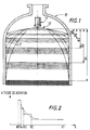
- FIG. 1 represents an enclosure 10 equipped with a loading device 11, comprising a movable assembly 12, of the type described in EP-A-007,854 or EP-A-116,246.
- a loading device 11 comprising a movable assembly 12, of the type described in EP-A-007,854 or EP-A-116,246.
- the length paths T of the particles loaded in the enclosure varies as the level of these particles rises in the enclosure, and it is necessary to interrupt the loading several times to adapt the speed of rotation of the moving element, the speed of rotation increasing when passing from a first level H 1 to successive levels H 2 , ..., H 5 as the enclosure fills.
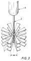
- this crew mobile includes three sets of eight straps semi-rigid 1, arranged at three spaced levels vertically.
- the strips 1 here have a trapezoidal shape and are articulated on the same motor shaft 2 around axes horizontal, on which they are for example mounted swivel, so that it can be lifted under the effect of centrifugal force, when driven in rotation by the motor means.
- a pipe feeds a hopper of storage 4 arranged above the strips 1, so as to pour the particles to be distributed onto these strips.
- the strips 1 of different stages of the moving equipment are arranged at vertical to each other, and like them are driven by the same motor shaft 2, they remain in this same relative position throughout the particle distribution.
- the two reactors are respectively loaded with the same mobile equipment.
- the crew straps are all identical and distributed according to three levels and arranged symmetrically with respect to the axis of rotation, to each of these levels. These strips, eight in number per level, are trapezoidal in shape. They are made in reinforced rubber, and measure 70 centimeters in length, 5 and 10 centimeters for small and large widths, and 0.6 cm thick.
- Each of the two loadings is carried out with a rate of vacuum of the different moving assembly, as indicated in the Table 1 below. This is achieved with provisions different straps at each of the three levels of the crew.
- the vacuum rate of 52% (crew adjustment mobile for loading the reactor R2) is the value maximum obtained for this type of straps and therefore corresponds to a provision thereof consistent with this invention.
- the vacuum rate of 4% (crew adjustment mobile for loading the reactor R1) corresponds to a arrangement of strips of the type of the prior art of the Applicant (see FR-A-2538795 on this subject).
Landscapes
- Chemical & Material Sciences (AREA)
- Engineering & Computer Science (AREA)
- Mechanical Engineering (AREA)
- Organic Chemistry (AREA)
- Chemical Kinetics & Catalysis (AREA)
- Devices And Processes Conducted In The Presence Of Fluids And Solid Particles (AREA)
- Feeding, Discharge, Calcimining, Fusing, And Gas-Generation Devices (AREA)
- Filling Or Emptying Of Bunkers, Hoppers, And Tanks (AREA)
- Mixers Of The Rotary Stirring Type (AREA)
- Filling Of Jars Or Cans And Processes For Cleaning And Sealing Jars (AREA)
- Solid State Image Pick-Up Elements (AREA)
- Manufacture, Treatment Of Glass Fibers (AREA)
- Processing Of Meat And Fish (AREA)
- Catalysts (AREA)
Claims (10)
- Verfahren zur gleichförmigen Verteilung eines Feststoffmaterials in zerteilter Form in einem Behälter, bei welchem das Feststoffmaterial auf ein bewegliches Aggregat herabfällt, das eine durch einen Antriebsmotor zur Rotation angetriebene Welle (2) und mit dieser Welle drehstarr verbundene Ablenkelemente (1) aufweist, die auf verschiedenen vertikal versetzten Niveaus bzw. Etagen um die Welle angeordnet sind,
dadurch gekennzeichnet, daß
jeweils jedes Niveau bzw. jede Etage mit der gleichen Anzahl Ablenkelemente (1) von im wesentlichen gleicher Form versehen ist, daß diese Ablenkelemente (1) bezüglich der Rotationswelle symmetrisch angeordnet sind, daß die Ablenkelemente der verschiedenen einzelnen Niveaus bzw. Etagen jeweils vertikal übereinander ausgerichtet angeordnet sind, und daß das bewegliche Aggregat als Ganzes einen prozentualen Leer-bzw. Freianteil zwischen 30 und 80 aufweist. - Verfahren nach Anspruch 1, dadurch gekennzeichnet, daß die Drehzahl der Ablenkelemente (1) zwischen 25 und 140 U/min und vorzugsweise zwischen 40 und 140 U/min beträgt.
- Vorrichtung zur gleichförmigen Verteilung eines Feststoffmaterials in zerteilter Form in einem Behälter, welche im oberen Teil des Behälters eine Aufgabevorrichtung (3) zur Zufuhr des zu verteilenden Feststoffmaterials in den Behälter aufweist, welche das Feststoffmaterial im wesentlichen vertikal in den Behälter einschüttet, sowie ein in dem Behälter unterhalb der Aufgabevorrichtung angeordnetes bewegliches Aggregat, welches eine von einem Antriebsmotor zur Rotation angetriebene Welle (2) sowie mit dieser Welle drehfest verbundene Ab-bzw. Umlemkelemente (1), die auf mehreren vertikal versetzten Niveaus bzw. Etagen um diese Welle angeordnet sind, aufweist,
dadurch gekennzeichnet, daß
auf jedem Niveau bzw. Etage jeweils eine gleiche Anzahl Ablenkelemente (1) von im wesentlichen gleicher Form vorgesehen ist, daß die Ablenkelemente (1) der verschiedenen Niveaus bzw. Etagen jeweils vertikal übereinander ausgerichtet angeordnet sind, und daß die Verbindungsmittel der Ablenkelemente (1) mit der Welle (2) so ausgebildet sind, daß auf jedem Niveau bzw. jeder Etage diese Elemente jeweils dieselbe Drehzahl besitzen und während des gesamten Beschickungsvorgangs des Behälters vertikal miteinander ausgerichtet bleiben, wobei das bewegliche Aggregat einen prozentualen Leer- bzw. Freianteil zwischen 30 und 80 aufweist. - Vorrichtung nach Anspruch 3, dadurch gekennzeichnet, daß die Ablenkelemente (1) in an sich bekannter Weise an der Welle gelenkig befestigt sind, derart, daß sie sich unter der Wirkung der Zentrifugalkraft aufrichten können.
- Vorrichtung nach einem der Ansprüche 3 und 4, dadurch gekennzeichnet, daß die Ablenkelemente (1) auf wenigstens zwei, vorzugsweise drei oder vier vertikal vesetzten Niveaus bzw. Etagen angeordnet sind.
- Vorrichtung nach einem der Ansprüche 3 bis 5, dadurch gekennzeichnet, daß die Niveaus bzw. Etagen der Ablenkelemente (1) voneinander einen Abstand zwischen 2 und 14 cm, vorzugsweise zwischen 4 und 8 cm, besitzen.
- Vorrichtung nach einem der Ansprüche 2 bis 6, dadurch gekennzeichnet, daß die Ablenkelemente (1) nachgiebig-biegsame Peitschen- bzw. Schlagelemente sind.
- Vorrichtung nach Anspruch 7, dadurch gekennzeichnet, daß die Zahl der auf jedem Niveau bzw. jeder Etage angeordnten biegsamen Schlagelemente (1) zwischen 2 und 12, und vorzugsweise zwischen 4 und 12, beträgt, wobei diese Schlagelemente symmetrisch bezüglich der Rotationswelle (2) angeordnet sind.
- Vorrichtung nach einem der Ansprüche 7 und 8, dadurch gekennzeichnet, daß die Längsabmessung der Schlagelemente zwischen 10 cm und 2 m, und vorzugsweise zwischen 10 cm und 1 m, beträgt.
- Anwendung des Verfahrens nach einem der Ansprüche 1 und 2, oder einer Vorrichtung nach einem der Ansprüche 3 bis 9, zur Beschickung von Behältern mit einem Durchmesser von mehr als 5 m.
Applications Claiming Priority (2)
| Application Number | Priority Date | Filing Date | Title |
|---|---|---|---|
| FR9512334 | 1995-10-20 | ||
| FR9512334A FR2740123B1 (fr) | 1995-10-20 | 1995-10-20 | Procede et dispositif pour la distribution uniforme d'un solide sous forme divisee dans une enceinte |
Publications (2)
| Publication Number | Publication Date |
|---|---|
| EP0769462A1 EP0769462A1 (de) | 1997-04-23 |
| EP0769462B1 true EP0769462B1 (de) | 1999-11-24 |
Family
ID=9483732
Family Applications (1)
| Application Number | Title | Priority Date | Filing Date |
|---|---|---|---|
| EP96402138A Expired - Lifetime EP0769462B1 (de) | 1995-10-20 | 1996-10-09 | Verfahren und Vorrichtung zum gleichmässigen Verteilen von Feststoffen in fein verteilter Form, in einem Behälter |
Country Status (11)
| Country | Link |
|---|---|
| US (1) | US5758699A (de) |
| EP (1) | EP0769462B1 (de) |
| JP (1) | JP4033933B2 (de) |
| AT (1) | ATE186894T1 (de) |
| CZ (1) | CZ306196A3 (de) |
| DE (1) | DE69605268T2 (de) |
| DK (1) | DK0769462T3 (de) |
| ES (1) | ES2140806T3 (de) |
| FR (1) | FR2740123B1 (de) |
| GR (1) | GR3031975T3 (de) |
| HU (1) | HUP9602897A3 (de) |
Families Citing this family (25)
| Publication number | Priority date | Publication date | Assignee | Title |
|---|---|---|---|---|
| FR2812824B1 (fr) * | 2000-08-10 | 2003-05-30 | Total Raffinage Distribution | Nouveau procede de chargement homogene de particules solides dans une enceinte |
| FR2818161B1 (fr) * | 2000-12-20 | 2003-02-21 | Total Raffinage Distribution | Procede de chargement d'une enceinte avec des particules solides |
| NO317083B1 (no) * | 2002-09-27 | 2004-08-02 | Catalyst Services Inc | Fremgangsmate for fylling av partikulaert materiale i vertikale ror |
| US7121309B2 (en) | 2004-09-16 | 2006-10-17 | Buchen-Ics Bv | Loading device |
| FR2882029B1 (fr) | 2005-02-14 | 2011-03-11 | Commissariat Energie Atomique | Dispositif de distribution d'au moins un materiau granulaire dans un recipient, dispositif de remplissage et procede de remplissage utilisant un tel dispositif |
| JP2008534259A (ja) * | 2005-03-25 | 2008-08-28 | キャタリスト・サービシーズ・インコーポレイテッド | チューブを触媒および/または他の粒子で満たす粒子充填装置および方法 |
| US8025472B2 (en) * | 2007-06-01 | 2011-09-27 | Catalyst Services, Inc. | Catalyst loading system |
| GB2462797B (en) * | 2008-05-30 | 2012-08-08 | Catalyst Handling Res & Engineering Ltd | Particulate levelling system |
| FR2940641B1 (fr) * | 2008-12-31 | 2013-02-01 | Total Raffinage Marketing | Dispositif pour le chargement de particules solides dans une enceinte |
| FR2949755B1 (fr) * | 2009-09-09 | 2012-09-28 | Olivier Girard | Dispositif de chargement dense d'un solide divise dans une enceinte |
| FR2954302B1 (fr) | 2009-12-21 | 2012-05-25 | Total Raffinage Marketing | Dispositif pour le chargement de particules solides dans une enceinte |
| DE102011115996B3 (de) * | 2011-10-14 | 2013-01-17 | Trautwein Sb-Technik Gmbh | Verteileinrichtung für Rücknahmeeinrichtungen von Getränkebehältnissen |
| RU2609408C2 (ru) | 2011-10-20 | 2017-02-01 | Акцо Нобель Кемикалз Интернэшнл Б.В. | Способ очистки жидкого сырья, содержащего мхк и дхк |
| US9505693B2 (en) | 2011-10-20 | 2016-11-29 | Akzo Nobel Chemicals International B.V. | Process for the hydrodechlorination of a liquid feed comprising dichloroacetic acid |
| FR2997315B1 (fr) * | 2012-10-29 | 2021-05-21 | Total Raffinage Marketing | Gestion du chargement en particules solides d'un reacteur |
| MX380594B (es) | 2015-03-17 | 2025-03-12 | Akzo Nobel Chemicals Int Bv | Proceso para la purificacion de acido monocloroacetico. |
| WO2016176604A1 (en) | 2015-04-29 | 2016-11-03 | Precision Consulting Services, LLC | Loading vertical tubes with particulate material |
| US10201792B2 (en) * | 2015-05-14 | 2019-02-12 | Sabic Global Technologies B.V. | Reactors and reactor-internal devices for dehydrogenation of hydrocarbons |
| AR104892A1 (es) | 2015-06-12 | 2017-08-23 | Akzo Nobel Chemicals Int Bv | Proceso para la hidrodecloración de una alimentación que comprende ácido dicloroacético |
| CN105800266A (zh) * | 2016-05-30 | 2016-07-27 | 苏州速腾电子科技有限公司 | 抛洒装置 |
| CN105836395A (zh) * | 2016-05-30 | 2016-08-10 | 苏州速腾电子科技有限公司 | 喷洒装置 |
| WO2018077639A1 (en) * | 2016-10-26 | 2018-05-03 | Basf Se | Method for discharging superabsorbent particles from a silo and filling them into bulk containers |
| US10427113B2 (en) | 2017-07-18 | 2019-10-01 | Cnh Industrial Canada, Ltd. | Horizontal product distribution system using static baffles in a distributor |
| FR3091490B1 (fr) | 2019-01-04 | 2021-01-29 | Total Raffinage Chimie | Distribution de particules solides dans une enceinte |
| FR3131547A1 (fr) | 2021-12-31 | 2023-07-07 | Arkema France | Mélange de solides inorganiques |
Family Cites Families (8)
| Publication number | Priority date | Publication date | Assignee | Title |
|---|---|---|---|---|
| US2655273A (en) | 1949-11-07 | 1953-10-13 | Phillips Petroleum Co | Method and apparatus for evenly distributing solid contact material |
| US3668115A (en) | 1970-03-27 | 1972-06-06 | Atlantic Richfield Co | Process for charging catalyst |
| BE789066A (fr) * | 1971-09-24 | 1973-03-21 | Atlantic Richfield Co | Procede ameliore de chargement de catalyseur dans un reacteur |
| US3949908A (en) * | 1974-10-25 | 1976-04-13 | Atlantic Richfield Company | Apparatus and method for distributing particulate material over a zone |
| DE2546445A1 (de) | 1974-10-25 | 1976-04-29 | Atlantic Richfield Co | Verfahren und vorrichtung zum verteilen teilchenfoermigen materials |
| US3995753A (en) | 1975-07-31 | 1976-12-07 | Uop Inc. | Dispensing apparatus for particulate matter |
| FR2431449A1 (fr) | 1978-07-20 | 1980-02-15 | Raffinage Cie Francaise | Dispositif de repartition d'un solide divise dans une enceinte |
| FR2538795B1 (fr) * | 1982-12-30 | 1987-01-02 | Raffinage Cie Francaise | Perfectionnements aux dispositifs de remplissage d'une enceinte avec un solide sous forme particulaire |
-
1995
- 1995-10-20 FR FR9512334A patent/FR2740123B1/fr not_active Expired - Lifetime
-
1996
- 1996-10-09 AT AT96402138T patent/ATE186894T1/de active
- 1996-10-09 EP EP96402138A patent/EP0769462B1/de not_active Expired - Lifetime
- 1996-10-09 ES ES96402138T patent/ES2140806T3/es not_active Expired - Lifetime
- 1996-10-09 DE DE69605268T patent/DE69605268T2/de not_active Expired - Lifetime
- 1996-10-09 DK DK96402138T patent/DK0769462T3/da active
- 1996-10-18 HU HU9602897A patent/HUP9602897A3/hu unknown
- 1996-10-18 CZ CZ963061A patent/CZ306196A3/cs unknown
- 1996-10-21 JP JP27843196A patent/JP4033933B2/ja not_active Expired - Lifetime
- 1996-10-21 US US08/735,373 patent/US5758699A/en not_active Expired - Lifetime
-
1999
- 1999-11-29 GR GR990403068T patent/GR3031975T3/el unknown
Also Published As
| Publication number | Publication date |
|---|---|
| DK0769462T3 (da) | 2000-04-10 |
| JPH09220458A (ja) | 1997-08-26 |
| FR2740123A1 (fr) | 1997-04-25 |
| HUP9602897A2 (en) | 1997-06-30 |
| HU9602897D0 (en) | 1996-12-30 |
| ES2140806T3 (es) | 2000-03-01 |
| DE69605268T2 (de) | 2000-03-16 |
| FR2740123B1 (fr) | 1998-01-02 |
| HUP9602897A3 (en) | 1999-03-29 |
| EP0769462A1 (de) | 1997-04-23 |
| DE69605268D1 (de) | 1999-12-30 |
| CZ306196A3 (cs) | 1998-05-13 |
| JP4033933B2 (ja) | 2008-01-16 |
| US5758699A (en) | 1998-06-02 |
| GR3031975T3 (en) | 2000-03-31 |
| ATE186894T1 (de) | 1999-12-15 |
Similar Documents
| Publication | Publication Date | Title |
|---|---|---|
| EP0769462B1 (de) | Verfahren und Vorrichtung zum gleichmässigen Verteilen von Feststoffen in fein verteilter Form, in einem Behälter | |
| EP0007854B1 (de) | Verteilvorrichtung für Schüttgut in einem Raum | |
| EP0116246B1 (de) | Behälterfülleinrichtung mit Feststoffpartikeln | |
| EP0803286B1 (de) | Verfahren und Vorrichtung zur homogenen Beschickung von festen Katalysatorteilchen in einen Rohrreaktor | |
| CA2705392C (fr) | Dispositif et procede pour le chargement de particules solides dans une enceinte | |
| EP2370202B1 (de) | Vorrichtung zum laden von festen teilchen in eine kammer | |
| CA2784151C (fr) | Dispositif pour le chargement de particules solides dans une enceinte | |
| EP2029463B1 (de) | Vorrichtung und verfahren zum laden von festpartikeln in eine kammer | |
| RU179022U1 (ru) | Смеситель | |
| EP3677332B1 (de) | Verteilung von feststoffpartikeln in einem gehäuse | |
| EP1152819B1 (de) | Verfahren und vorrichtung zum erleichtern des befüllens vertikaler rohre mit hilfe eines partikelförmigen materials | |
| EP0592276B1 (de) | Austragvorrichtung und mit dieser Vorrichtung ausgerüsteter Lagerplatz | |
| FR2829107A1 (fr) | Procede et dispositif pour le chargement d'une enceinte avec des particules solides | |
| EP1351761B1 (de) | Verfahren zum laden einer kammer mit feststoffen | |
| WO2002011877A1 (fr) | Nouveau procede de chargement homogene de particules solides dans une enceinte | |
| FR2505998A1 (fr) | Procede et appareil pour couler une matiere amorphe refractaire de garnissage dans un recipient pour metal en fusion | |
| EP3677333A1 (de) | Verteilung von feststoffpartikeln in einem gehäuse | |
| FR2541315A1 (fr) | Dispositif pour tirer un monocristal d'un creuset | |
| EP0262035A1 (de) | Lager- und Transportbehälter, an seiner Basis versehen mit wenigstens einem Entleerungstrichter | |
| BE844749A (fr) | Appareil pour distribuer uniformement une matiere en particules | |
| EP2638958A1 (de) | Umsetzungssystem für bröckligen Feststoff mit Ladungsvorrichtung | |
| FR2596371A1 (fr) | Dispositif pour le chargement d'un produit en vrac dans une cuve verticale notamment dans une cuve de vinification | |
| CH631409A5 (fr) | Dispositif raclant, notamment pour les centrales a beton. | |
| EP2638957A1 (de) | Umsetzungssystem für bröckligen Feststoff mit Ladungsvorrichtung und Ladeverfahren für dieses Produkt |
Legal Events
| Date | Code | Title | Description |
|---|---|---|---|
| PUAI | Public reference made under article 153(3) epc to a published international application that has entered the european phase |
Free format text: ORIGINAL CODE: 0009012 |
|
| AK | Designated contracting states |
Kind code of ref document: A1 Designated state(s): AT BE CH DE DK ES FI GB GR IE IT LI LU NL PT SE |
|
| 17P | Request for examination filed |
Effective date: 19970901 |
|
| GRAG | Despatch of communication of intention to grant |
Free format text: ORIGINAL CODE: EPIDOS AGRA |
|
| GRAG | Despatch of communication of intention to grant |
Free format text: ORIGINAL CODE: EPIDOS AGRA |
|
| GRAH | Despatch of communication of intention to grant a patent |
Free format text: ORIGINAL CODE: EPIDOS IGRA |
|
| 17Q | First examination report despatched |
Effective date: 19990428 |
|
| GRAH | Despatch of communication of intention to grant a patent |
Free format text: ORIGINAL CODE: EPIDOS IGRA |
|
| GRAA | (expected) grant |
Free format text: ORIGINAL CODE: 0009210 |
|
| AK | Designated contracting states |
Kind code of ref document: B1 Designated state(s): AT BE CH DE DK ES FI GB GR IE IT LI LU NL PT SE |
|
| REF | Corresponds to: |
Ref document number: 186894 Country of ref document: AT Date of ref document: 19991215 Kind code of ref document: T |
|
| REG | Reference to a national code |
Ref country code: CH Ref legal event code: NV Representative=s name: FREI PATENTANWALTSBUERO Ref country code: CH Ref legal event code: EP |
|
| REF | Corresponds to: |
Ref document number: 69605268 Country of ref document: DE Date of ref document: 19991230 |
|
| REG | Reference to a national code |
Ref country code: IE Ref legal event code: FG4D Free format text: FRENCH |
|
| REG | Reference to a national code |
Ref country code: ES Ref legal event code: FG2A Ref document number: 2140806 Country of ref document: ES Kind code of ref document: T3 |
|
| GBT | Gb: translation of ep patent filed (gb section 77(6)(a)/1977) |
Effective date: 20000221 |
|
| REG | Reference to a national code |
Ref country code: PT Ref legal event code: SC4A Free format text: AVAILABILITY OF NATIONAL TRANSLATION Effective date: 19991126 |
|
| ITF | It: translation for a ep patent filed | ||
| REG | Reference to a national code |
Ref country code: DK Ref legal event code: T3 |
|
| REG | Reference to a national code |
Ref country code: IE Ref legal event code: FD4D |
|
| PLBE | No opposition filed within time limit |
Free format text: ORIGINAL CODE: 0009261 |
|
| STAA | Information on the status of an ep patent application or granted ep patent |
Free format text: STATUS: NO OPPOSITION FILED WITHIN TIME LIMIT |
|
| PG25 | Lapsed in a contracting state [announced via postgrant information from national office to epo] |
Ref country code: LU Free format text: LAPSE BECAUSE OF NON-PAYMENT OF DUE FEES Effective date: 20001009 |
|
| 26N | No opposition filed | ||
| REG | Reference to a national code |
Ref country code: GB Ref legal event code: IF02 |
|
| PGFP | Annual fee paid to national office [announced via postgrant information from national office to epo] |
Ref country code: IE Payment date: 20041013 Year of fee payment: 9 |
|
| PG25 | Lapsed in a contracting state [announced via postgrant information from national office to epo] |
Ref country code: IE Free format text: LAPSE BECAUSE OF NON-PAYMENT OF DUE FEES Effective date: 20051010 |
|
| REG | Reference to a national code |
Ref country code: IE Ref legal event code: MM4A |
|
| PGFP | Annual fee paid to national office [announced via postgrant information from national office to epo] |
Ref country code: PT Payment date: 20150921 Year of fee payment: 20 |
|
| PGFP | Annual fee paid to national office [announced via postgrant information from national office to epo] |
Ref country code: DK Payment date: 20151021 Year of fee payment: 20 |
|
| PGFP | Annual fee paid to national office [announced via postgrant information from national office to epo] |
Ref country code: CH Payment date: 20151021 Year of fee payment: 20 Ref country code: FI Payment date: 20151013 Year of fee payment: 20 Ref country code: GB Payment date: 20151021 Year of fee payment: 20 Ref country code: IT Payment date: 20151028 Year of fee payment: 20 Ref country code: DE Payment date: 20151022 Year of fee payment: 20 Ref country code: GR Payment date: 20151013 Year of fee payment: 20 |
|
| REG | Reference to a national code |
Ref country code: DE Ref legal event code: R082 Ref document number: 69605268 Country of ref document: DE Representative=s name: ANDRAE WESTENDORP PATENTANWAELTE PARTNERSCHAFT, DE Ref country code: DE Ref legal event code: R081 Ref document number: 69605268 Country of ref document: DE Owner name: TOTAL RAFFINAGE FRANCE, FR Free format text: FORMER OWNER: TOTAL RAFFINAGE DISTRIBUTION S.A., PUTEAUX, FR |
|
| PGFP | Annual fee paid to national office [announced via postgrant information from national office to epo] |
Ref country code: ES Payment date: 20151028 Year of fee payment: 20 Ref country code: AT Payment date: 20151022 Year of fee payment: 20 Ref country code: SE Payment date: 20151021 Year of fee payment: 20 Ref country code: NL Payment date: 20151021 Year of fee payment: 20 Ref country code: BE Payment date: 20151019 Year of fee payment: 20 |
|
| PG25 | Lapsed in a contracting state [announced via postgrant information from national office to epo] |
Ref country code: IT Free format text: LAPSE BECAUSE OF NON-PAYMENT OF DUE FEES Effective date: 20151009 |
|
| REG | Reference to a national code |
Ref country code: DE Ref legal event code: R071 Ref document number: 69605268 Country of ref document: DE |
|
| REG | Reference to a national code |
Ref country code: DK Ref legal event code: EUP Effective date: 20161009 |
|
| REG | Reference to a national code |
Ref country code: NL Ref legal event code: MK Effective date: 20161008 |
|
| REG | Reference to a national code |
Ref country code: CH Ref legal event code: PL |
|
| REG | Reference to a national code |
Ref country code: GB Ref legal event code: PE20 Expiry date: 20161008 |
|
| REG | Reference to a national code |
Ref country code: ES Ref legal event code: FD2A Effective date: 20161114 |
|
| REG | Reference to a national code |
Ref country code: AT Ref legal event code: MK07 Ref document number: 186894 Country of ref document: AT Kind code of ref document: T Effective date: 20161009 |
|
| REG | Reference to a national code |
Ref country code: SE Ref legal event code: EUG |
|
| PG25 | Lapsed in a contracting state [announced via postgrant information from national office to epo] |
Ref country code: GB Free format text: LAPSE BECAUSE OF EXPIRATION OF PROTECTION Effective date: 20161008 |
|
| REG | Reference to a national code |
Ref country code: GR Ref legal event code: MA Ref document number: 990403068 Country of ref document: GR Effective date: 20161010 |
|
| REG | Reference to a national code |
Ref country code: AT Ref legal event code: PC Ref document number: 186894 Country of ref document: AT Kind code of ref document: T Owner name: TOTAL RAFFINAGE FRANCE, FR Effective date: 20161220 |
|
| PG25 | Lapsed in a contracting state [announced via postgrant information from national office to epo] |
Ref country code: PT Free format text: LAPSE BECAUSE OF EXPIRATION OF PROTECTION Effective date: 20161018 Ref country code: ES Free format text: THE PATENT HAS BEEN ANNULLED BY A DECISION OF A NATIONAL AUTHORITY Effective date: 20161009 |