EP0769397A1 - Twist beam suspension - Google Patents
Twist beam suspension Download PDFInfo
- Publication number
- EP0769397A1 EP0769397A1 EP96116356A EP96116356A EP0769397A1 EP 0769397 A1 EP0769397 A1 EP 0769397A1 EP 96116356 A EP96116356 A EP 96116356A EP 96116356 A EP96116356 A EP 96116356A EP 0769397 A1 EP0769397 A1 EP 0769397A1
- Authority
- EP
- European Patent Office
- Prior art keywords
- vehicle
- twist beam
- outer tube
- disposed
- transverse direction
- Prior art date
- Legal status (The legal status is an assumption and is not a legal conclusion. Google has not performed a legal analysis and makes no representation as to the accuracy of the status listed.)
- Granted
Links
Images


Classifications
-
- B—PERFORMING OPERATIONS; TRANSPORTING
- B60—VEHICLES IN GENERAL
- B60G—VEHICLE SUSPENSION ARRANGEMENTS
- B60G21/00—Interconnection systems for two or more resiliently-suspended wheels, e.g. for stabilising a vehicle body with respect to acceleration, deceleration or centrifugal forces
- B60G21/02—Interconnection systems for two or more resiliently-suspended wheels, e.g. for stabilising a vehicle body with respect to acceleration, deceleration or centrifugal forces permanently interconnected
- B60G21/04—Interconnection systems for two or more resiliently-suspended wheels, e.g. for stabilising a vehicle body with respect to acceleration, deceleration or centrifugal forces permanently interconnected mechanically
- B60G21/05—Interconnection systems for two or more resiliently-suspended wheels, e.g. for stabilising a vehicle body with respect to acceleration, deceleration or centrifugal forces permanently interconnected mechanically between wheels on the same axle but on different sides of the vehicle, i.e. the left and right wheel suspensions being interconnected
- B60G21/051—Trailing arm twist beam axles
- B60G21/052—Mounting means therefor
-
- B—PERFORMING OPERATIONS; TRANSPORTING
- B60—VEHICLES IN GENERAL
- B60G—VEHICLE SUSPENSION ARRANGEMENTS
- B60G2200/00—Indexing codes relating to suspension types
- B60G2200/20—Semi-rigid axle suspensions
- B60G2200/21—Trailing arms connected by a torsional beam, i.e. twist-beam axles
-
- B—PERFORMING OPERATIONS; TRANSPORTING
- B60—VEHICLES IN GENERAL
- B60G—VEHICLE SUSPENSION ARRANGEMENTS
- B60G2200/00—Indexing codes relating to suspension types
- B60G2200/40—Indexing codes relating to the wheels in the suspensions
- B60G2200/445—Self-steered wheels
-
- B—PERFORMING OPERATIONS; TRANSPORTING
- B60—VEHICLES IN GENERAL
- B60G—VEHICLE SUSPENSION ARRANGEMENTS
- B60G2200/00—Indexing codes relating to suspension types
- B60G2200/40—Indexing codes relating to the wheels in the suspensions
- B60G2200/462—Toe-in/out
-
- B—PERFORMING OPERATIONS; TRANSPORTING
- B60—VEHICLES IN GENERAL
- B60G—VEHICLE SUSPENSION ARRANGEMENTS
- B60G2202/00—Indexing codes relating to the type of spring, damper or actuator
- B60G2202/10—Type of spring
- B60G2202/13—Torsion spring
- B60G2202/136—Twist-beam type arrangement
-
- B—PERFORMING OPERATIONS; TRANSPORTING
- B60—VEHICLES IN GENERAL
- B60G—VEHICLE SUSPENSION ARRANGEMENTS
- B60G2204/00—Indexing codes related to suspensions per se or to auxiliary parts
- B60G2204/10—Mounting of suspension elements
- B60G2204/14—Mounting of suspension arms
- B60G2204/143—Mounting of suspension arms on the vehicle body or chassis
- B60G2204/1434—Mounting of suspension arms on the vehicle body or chassis in twist-beam axles arrangement
-
- B—PERFORMING OPERATIONS; TRANSPORTING
- B60—VEHICLES IN GENERAL
- B60G—VEHICLE SUSPENSION ARRANGEMENTS
- B60G2204/00—Indexing codes related to suspensions per se or to auxiliary parts
- B60G2204/40—Auxiliary suspension parts; Adjustment of suspensions
- B60G2204/41—Elastic mounts, e.g. bushings
-
- B—PERFORMING OPERATIONS; TRANSPORTING
- B60—VEHICLES IN GENERAL
- B60G—VEHICLE SUSPENSION ARRANGEMENTS
- B60G2204/00—Indexing codes related to suspensions per se or to auxiliary parts
- B60G2204/40—Auxiliary suspension parts; Adjustment of suspensions
- B60G2204/41—Elastic mounts, e.g. bushings
- B60G2204/4104—Bushings having modified rigidity in particular directions
-
- B—PERFORMING OPERATIONS; TRANSPORTING
- B60—VEHICLES IN GENERAL
- B60G—VEHICLE SUSPENSION ARRANGEMENTS
- B60G2204/00—Indexing codes related to suspensions per se or to auxiliary parts
- B60G2204/40—Auxiliary suspension parts; Adjustment of suspensions
- B60G2204/45—Stops limiting travel
Definitions
- the present invention relates to a twist beam suspension consisting of a twist beam which is disposed so as to extend in the transverse direction of a vehicle, and a pair of trailing arms which are disposed at longitudinal ends of the twist beam so as to extend in the longitudinal direction of the vehicle.
- FIG. 7 shows a plan view of a twist beam rear suspension.
- An example of such a twist beam rear suspension is disclosed in Japanese Patent Application Laid-Open (JP-A) No. 4-283114.
- such a twist beam rear suspension consists of a twist beam 100 which has an open (i.e., substantially C-shaped) cross-sectional configuration and which is disposed so as to extend in the transverse direction of a vehicle, and a pair of trailing arms 102 and 104 disposed at longitudinal ends of the twist beam 100 so as to extend in the longitudinal direction of the vehicle.
- FIG. 8 shows an enlarged view of the bush 110 located on the right side in FIG. 7.
- the bush 110 is composed of a cylindrical inner tube 114, a cylindrical outer tube 116 disposed so as to be apart from the out peripheral portion of the inner tube 114, and a rubber member 118 adhered by vulcanization between the inner tube 114 and the outer tube 116.
- an inner-side bracket 120 is mounted to a vehicle body such that the bracket 120 abuts the inner end of the inner tube 114.
- an outer-side bracket 122 is mounted to the vehicle body such that the bracket 122 abuts the outer end of the inner tube 114.
- a bolt 124 is inserted into the inner tube 114 after passing through the outer-side bracket 122, and a nut 126 is screwed onto the bolt 124, whereby the trailing arm 102 is swingably connected to the vehicle body.
- the bush 112 on the left side in FIG. 7 has the same structure.
- the distance A' between the inner end of the outer tube 116 and the outside surface of the inner-side bracket 120 is designed to be substantially equal to the distance B' between the outer end of the outer tube 116 and the inner side surface of the outer-side bracket 122. In some cases, the distance A' becomes larger than the distance B', because of the conditions of assembly and the like. Therefore, the conventional twist beam rear suspension has a drawback that the twist beam 100 receives a compression force when an excessive lateral force acts on one of the wheels.
- the lateral force F' is transmitted to the vehicle body via the right-side trailing arm 102, the twist beam 100, the left-side trailing arm 104, the outer tube of the left-side bush 112 and the outer-side bracket 122 located on the left side of the twist beam 100.
- the twist beam 100 is subjected to the leftward lateral force F' and a reaction force which is transmitted from the outer-side bracket 122 located on the left side of the twist beams 100 to the outer tube of the left-side bush 112 (i.e., the left-side trailing arm 104).
- a compression force acts on the twist beam 100.
- This compression force as well as the open cross-sectional configuration of the twist beam 100 adversely affects the strength of the twist beam 100.
- a twist beam suspension which includes a twist beam which is disposed so that the longitudinal direction thereof runs along with the transverse direction of a vehicle, and a pair of trailing arms being connected to a body of the vehicle and each of which is disposed at a respectively different longitudinal end of the twist beam and is disposed such that the longitudinal direction thereof runs along the longitudinal direction of the vehicle.
- the twist beam suspension further includes restricting means which restricts inward displacement of the pair of trailing arms relative to the body of the vehicle in the transverse direction of the vehicle prior to restricting outward displacement of the pair of trailing arms relative to the body of the vehicle in the transverse direction of the vehicle.
- the twist beam suspension according to the first aspect further includes a connecting member for connecting a front end portion of each of the trailing arms in the longitudinal direction of the vehicle to the body of the vehicle.
- the connecting member has an inner tube and an outer tube, and the inner tube is provided at one of the trailing arm and the body of the vehicle and the outer tube is provided at the other.
- the restricting means is a stopper member which restricts relative displacement between the outer and inner tubes of the connecting member.
- the restricting means restricts inward displacement of the suspension relative to the body of the vehicle in the transverse direction of the vehicle prior to restricting outward displacement of the suspension relative to the body of the vehicle in the transverse direction of the vehicle. Therefore, the twist beam is not subjected to a compression force which would act on the twist beam when the above-described inward and outward displacements are restricted in the reverse order. Accordingly, the twist beam suspension has a structure advantageous to the strength of the twist beam.
- the restricting means is composed of a stopper member which restricts relative displacement between the outer and inner tubes of the connecting member which connects the front end portion of each of the trailing arms to the body of the vehicle. Therefore, the structure of the restricting means can be simplified.
- FIGS. 1 and 2 A first embodiment of the present invention will now be described with reference to FIGS. 1 and 2.
- arrow FR indicates the forward direction of a vehicle
- arrow RH indicates the direction toward the right side of the vehicle
- arrow LH indicates the direction toward the left side of the vehicle.
- a twist beam rear suspension consists of a twist beam 10 which is disposed so as to extend in the transverse direction of a vehicle, and a pair of trailing arms 12 and 14 which are disposed at opposite longitudinal ends of the twist beam 10 so as to extend in the longitudinal direction of the vehicle.
- the twist beams 10 has an open cross section of a generally U-like shape. Reinforcing gussets 16 are welded to the connecting portions at which the twist beam 10 and the trailing arms 12 and 14 are joined to each other.
- Cylindrical bush press-fitting portions 22 and 24 are integrally formed at the front end portions of the trailing arms 12 and 14 in the longitudinal direction of the vehicle.
- bushes 26 and 28 serving as connecting members such that their axes extend in the transverse direction of the vehicle.
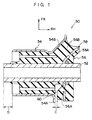
- FIG. 1 shows an enlarged view of the bush 26 located on the right side in FIG. 2.
- the bush 26 is composed of a cylindrical inner tube 30, a cylindrical outer tube 32 which is disposed so as to surround the inner sleeve 30 with a spacing formed therebetween and which is press-inserted into the bush press-fitting portion 22, and a rubber member 34 which is disposed between the inner tube 30 and the outer tube 32 and joined thereto though vulcanization and which functions as an elastic member.
- an inner-side bracket 36 On the inner side of the inner tube 30 in the transverse direction of the vehicle is disposed an inner-side bracket 36 which is mounted to the body of the vehicle and which serves as a restricting means. The inner-side bracket 36 abuts the inner end of the inner tube 30.
- an outer-side bracket 38 which is mounted to the body of the vehicle.
- the outer-side bracket 38 abuts the outer end of the inner tube 30.
- a bolt 40 is inserted into the inner tube 30 after passing through the outer-side bracket 38, and a nut 42 is screwed onto the bolt 40, whereby the trailing arm 12 located on the right side in FIG. 2 is swingably connected to the body of the vehicle.
- the bush 112 on the left side in FIG. 7 has the same structure.
- the distance A between the inner end of the outer tube 32 of the bush 26 and the outwardly facing surface of the inner-side bracket 36 is designed to be smaller than the distance B between the outer end of the outer tube 32 and the inwardly facing surface of the outer-side bracket 38. This designed is also applied to the bush 28 located on the left side in FIG. 2.
- the entire rear suspension tends to move leftward in FIG. 2 due to the lateral force F.
- the distance A between the inner end of the outer tube 32 of the bush 26 and the outwardly facing surface of the inner-side bracket 36 is smaller than the distance B between the outer end of the outer tube 32 and the inwardly facing surface of the outer-side bracket 38. Therefore, the inner end of the outer tube 32 of the right-side bush 26 abuts the inner-side bracket 36 before the outer end of the outer tube 32 of the left-side bush 28 abuts the outer-side bracket 38.
- the lateral force F is input from the right-side wheel to the right-side trailing arm 12, and then transmitted to the body of the vehicle via the outer tube 32 of the bush 26 and the inner-side bracket 36. That is, in the present embodiment, inward displacement of the suspension relative to the body in the transverse direction of the vehicle is restricted prior to outward displacement of the suspension relative to the body in the transverse direction of the vehicle. Therefore, the twist beam 10 is not subjected to compression force.
- the distance A between the inner end of the outer tube 32 of the bush 26 and the outwardly facing surface of the inner-side bracket 36 is smaller than the distance B between the outer end of the outer tube 32 and the inwardly facing surface of the outer-side bracket 38, inward displacement of the suspension relative to the body in the transverse direction of the vehicle is restricted prior to outward displacement of the suspension relative to the body in the transverse direction of the vehicle. Therefore, a structure which is advantageous to the strength of the twist beam 10 can be obtained.
- inward displacement of the suspension relative to the body in the transverse direction of the vehicle is first restricted by causing the inner end of the outer tube 32 of the bush 26 to abut the inner-side bracket 36. This simplifies the structure of the rear suspension.
- FIG. 3 shows a horizontal cross section of a bush 50 which is disposed on the left side of the above-described twist beam rear suspension and which serves as a connecting member.
- the bush 50 is composed of coaxially disposed internal and outer tubes 52 and 54, and a rubber member 56 which is disposed between the sleeves 52 and 54 and joined thereto through vulcanization and which serves as an elastic member.
- the outer tube 54 is formed such that its axial length at a rear portion located on the rear side of the inner tube 52 in the longitudinal direction of the vehicle is shorter than the axial length at a front portion located on the front side of the inner tube 52 in the longitudinal direction of the vehicle, and that the inner end of the rear portion is bent toward the back of the vehicle. This bent portion will be refereed to as a "bent portion 54A" hereinafter.
- a plate 58 is welded to the outer circumferential surface of the inner tube 52 such that the plate 58 extends in the substantially radial direction of the inner tube 52.
- a projecting portion 56A is formed so as to project toward the bent portion 54A of the inner tube 52. This projecting portion 56A is integrally formed together with the rubber member 56 during a vulcanization/forming process.
- the rubber member 56 which is formed in a vicinity of the bent portion 54A, is flush with the end surface of the bent portion 54A, and that a spacing 60 is formed between the projecting portion 56A and the bent portion 54A.
- the size C of the spacing 60 is designed to be smaller than the distance D between the outer end of the outer tube 54 of the bush 50 and the external end of the inner tube 52 (which corresponds to the inwardly facing surface of the above-described outer-side bracket 38 although the outer-side bracket 38 is not illustrated in FIG. 3).
- the inner end portion and its neighboring portion of the outer tube 54 are bent so as to obliquely extend toward the front of the vehicle.
- This bent portion will be referred to as a "slant portion 54B of the outer tube 54" hereinafter.
- the front portion of the plate 58 in the longitudinal direction of the vehicle is bent so as to extend in substantially parallel with the slant portion 54B.
- This bent portion will be refereed to as a "slant portion 58A of the plate 58" hereinafter.
- the space between these slant portions 54B and 58A is filled with the rubber material 56.
- This portion of the rubber material will be referred to as an "expanded portion 56B" hereinafter.
- twist beam rear suspension of the present embodiment having the above-described structure, as in the first embodiment, inward displacement of the suspension relative to the body in the transverse direction of the vehicle is restricted prior to prior to outward displacement of the suspension relative to the body in the transverse direction of the vehicle. Therefore, the above-described structure of the twist beam rear suspension is advantageous to the strength of the twist beam 10. That is, when an excessive lateral force F acts rightward on the left wheel, the entire rear suspension tends to move rightward due to the lateral force F.
- the size C of the spacing 60 is set to be smaller than the distance D between the outer end of the outer tube 54 and the outer end of the inner tube 52, the inner end (bent portion 54A) of the outer tube 54 of the left-side bush 50 abuts the projecting portion 56A before the outer end of the outer tube 54 of the right-side bush 50 abuts the outer-side bracket 38. Accordingly, the same effects as those of the first embodiment can be obtained.
- the bush 50 of the present embodiment has steer angle correcting means.
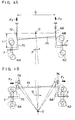
- FIG. 4A shows a schematic view of a twist beam rear suspension which has no toe correcting function.
- L is the arm length of the trailing arms 68 and 70 (in FIG. 4A, the distance in the longitudinal direction of the vehicle between the left-side bush 72 and the center of the wheel 64)
- D is the distance between the right-side bush 66 and the left-side bush 72.
- OS steer angle
- the steer angle of the twist beam 74 varies in the OS direction, the driving stability is adversely affected thereby. Therefore, the steer angle must be corrected toward the direction of causing an under steer (hereinafter referred to as "US").
- US under steer
- a characteristic is give to the bushes 76 and 78 such that when a rightward lateral force F acts on the right and left wheels 62 and 64, a rightward force F Y acts on the right-side bush 76 so as to displace the right-side bush 76 in the backward direction as well as in the rightward direction, and a rightward force F Y acts on the left-side bush 78 so as to displace the left-side bush 78 in the forward direction as well as in the rightward direction, as shown in FIG. 4B. Due to this characteristic, the twist beam 74 rotates in the clockwise direction about a rotational center O, so that the steering angle is corrected toward the US direction (in the direction of arrow Q).
- a toe correcting function is obtained. That is, when a rightward lateral force F acts on the bush 50, a rightward lateral force F Y acts on the outer tube 54, so that the outer tube 54 is displaced in the rightward direction in FIG. 4B. At the same time, the expanded portion 56B sandwiched between the slant portion 54B of the outer tube 54 and the slant portion 58A of the plate 58 is compressed, and a reaction force is generated. Since this reaction force acts on the outer tube 54 as a forward longitudinal force F X , the outer tube 54 is also displaced in the forward direction in FIG. 4B.
- the left-side bush 50 is displaced from the position indicated by a broken line to the position indicated by a continuous line in the direction of arrow Q.
- the bush 50 disposed on the right side in FIG. 4B is also displaced in the same manner. Accordingly, the bushes 50 according to the present embodiment can provide a toe correcting function.
- the bushes 50 of the present embodiment have both the stopper function and the toe correcting function, the bushes 50 consequently have improved durability against input loads in the transverse direction of the vehicle.
- the spring constant of each bush in the longitudinal direction of the vehicle so as to allow the wheels to easily move in the longitudinal direction of the vehicle.
- a lateral force F to the right and left wheels a larger variation in the steer angle is caused by the forward and backward longitudinal forces F X , so that the tendency of OS becomes stronger.
- FIG. 5 is a graph which shows the spring characteristic of the bush 50 in the transverse direction of the vehicle.
- the horizontal axis represents the amount of the lateral displacement of the outer tube 54 of the bush 50, and when the amount of displacement takes a positive value, it means that the outer tube 54 moves inwardly in the transverse direction of the vehicle (outwardly in the bush 50 disposed on the left side).
- the vertical axis represents the lateral force acting on the outer tube 54.
- the characteristic curve a shows the characteristic of the bush 50 itself, while the characteristic curve b shows the characteristic of the bush 50 which is used as the bush of the above-described twist beam suspension. As is apparent from the characteristic curve b, excessive lateral displacement of the bush 50 due to lateral input loads is suppressed, and this is advantageous to the durability of the bush 50.
- FIG. 6 shows a horizontal cross section of a bush 80 serving as a connecting member which has a structure different from that of the above-described bush 50 but has a similar function as that of the bush 50.
- the bush 80 is disposed on the right side of the above-described twist beam rear suspension.
- the bush 80 is composed of an inner tube 82, an outer tube 84, and a rubber member 86 which is disposed between the sleeves 82 and 84 and joined thereto through vulcanization.
- a flange portion 88 At the inner end of the inner tube 82 is provided.
- the flange portion 88 has a projecting portion 88A which has a rectangular cross section and which projects from the inner end of the inner tube 82 toward the rear of the vehicle, and a slant portion 88B which has a substantially triangular cross section and which projects from the inner end of the inner tube 82 toward the front of the vehicle.
- the outer tube 84 has the same shape as that of the outer tube 54 of the above-described bush 50, and it has a bent portion 84A and a slant portion 84B.
- the rubber member 86 has a portion serving as an elastic member which is joined through vulcanization to the outer end of the projecting portion 88A of the flange portion 88 (hereinafter this portion will be referred to as a "flange-side rubber portion 86A"), and a portion serving as an elastic member which is joined through vulcanization to the inner end of the bent portion 84A of the outer tube 84 (hereinafter this portion will be referred to as a "outer tube-side rubber portion 86B").
- Each of these rubber portions has a predetermined thinness, so that a spacing 90 of a size C is formed between the flange-side rubber portion 86A and the outer tube-side rubber portion 86B.
- the distance between the outer end of the inner tube 82 and the outer end of the outer tube 84 is set to D.
- the space between the slant portion 88B of the flange portion 88 and the slant portion 84B of the outer tube 84 is filled with the rubber material 86.
- an expanded portion 86C having the same function as that of the expanded portion 50B of the bush 50 is formed.
- the bush 80 has substantially the same function as the bush 50 and provides action and effects similar to those provided by the bush 50.
- means for transferring force is applied to the vehicle in the transverse direction of the vehicle when the vehicle is traveling in a curve, to the body of the vehicle through mainly the one of the trailing arms, which is at the outerwheel in the curve, and preventing said force from being applied to the twist beam.
Landscapes
- Engineering & Computer Science (AREA)
- Mechanical Engineering (AREA)
- Vehicle Body Suspensions (AREA)
Abstract
Description
- The present invention relates to a twist beam suspension consisting of a twist beam which is disposed so as to extend in the transverse direction of a vehicle, and a pair of trailing arms which are disposed at longitudinal ends of the twist beam so as to extend in the longitudinal direction of the vehicle.
- FIG. 7 shows a plan view of a twist beam rear suspension. An example of such a twist beam rear suspension is disclosed in Japanese Patent Application Laid-Open (JP-A) No. 4-283114.
- As shown in FIG. 7, such a twist beam rear suspension consists of a
twist beam 100 which has an open (i.e., substantially C-shaped) cross-sectional configuration and which is disposed so as to extend in the transverse direction of a vehicle, and a pair of trailingarms twist beam 100 so as to extend in the longitudinal direction of the vehicle. - From the rear ends of these
trailing arms spindles bushes arms - FIG. 8 shows an enlarged view of the
bush 110 located on the right side in FIG. 7. As shown in FIG. 8, thebush 110 is composed of a cylindricalinner tube 114, a cylindricalouter tube 116 disposed so as to be apart from the out peripheral portion of theinner tube 114, and arubber member 118 adhered by vulcanization between theinner tube 114 and theouter tube 116. On the inner side of theinner tube 114 in the transverse direction of the vehicle, an inner-side bracket 120 is mounted to a vehicle body such that thebracket 120 abuts the inner end of theinner tube 114. Similarly, on the outer side of theinner tube 114 in the transverse direction of the vehicle, an outer-side bracket 122 is mounted to the vehicle body such that thebracket 122 abuts the outer end of theinner tube 114. In this state, abolt 124 is inserted into theinner tube 114 after passing through the outer-side bracket 122, and anut 126 is screwed onto thebolt 124, whereby thetrailing arm 102 is swingably connected to the vehicle body. Thebush 112 on the left side in FIG. 7 has the same structure. - In the above-described twist beam rear suspension, the distance A' between the inner end of the
outer tube 116 and the outside surface of the inner-side bracket 120 is designed to be substantially equal to the distance B' between the outer end of theouter tube 116 and the inner side surface of the outer-side bracket 122. In some cases, the distance A' becomes larger than the distance B', because of the conditions of assembly and the like. Therefore, the conventional twist beam rear suspension has a drawback that thetwist beam 100 receives a compression force when an excessive lateral force acts on one of the wheels. - That is, when an excessive lateral force F' acts leftward on the right wheel as shown in FIG. 7, the entire rear suspension tends to move leftward in FIG. 7 due to the lateral force F' . As described above, if the distance A' is stated larger than the distance B', the outer end of the
outer tube 116 of the left-side bush 112 abuts the outer-side bracket 122 before the inner end of theouter tube 116 of the right-side bush 110 abuts the inner-side bracket 120. Therefore, the lateral force F' is transmitted to the vehicle body via the right-sidetrailing arm 102, thetwist beam 100, the left-side trailing arm 104, the outer tube of the left-side bush 112 and the outer-side bracket 122 located on the left side of thetwist beam 100. At this time, thetwist beam 100 is subjected to the leftward lateral force F' and a reaction force which is transmitted from the outer-side bracket 122 located on the left side of thetwist beams 100 to the outer tube of the left-side bush 112 (i.e., the left-side trailing arm 104). Accordingly, a compression force acts on thetwist beam 100. This compression force as well as the open cross-sectional configuration of thetwist beam 100 adversely affects the strength of thetwist beam 100. - In view of the foregoing facts, it is an object of the present invention to provide a twist beam suspension which has a structure advantageous to the strength of a twist beam.
- According to a first aspect of the present invention, there is provided a twist beam suspension which includes a twist beam which is disposed so that the longitudinal direction thereof runs along with the transverse direction of a vehicle, and a pair of trailing arms being connected to a body of the vehicle and each of which is disposed at a respectively different longitudinal end of the twist beam and is disposed such that the longitudinal direction thereof runs along the longitudinal direction of the vehicle. The twist beam suspension further includes restricting means which restricts inward displacement of the pair of trailing arms relative to the body of the vehicle in the transverse direction of the vehicle prior to restricting outward displacement of the pair of trailing arms relative to the body of the vehicle in the transverse direction of the vehicle.
- According to a second aspect of the present invention, the twist beam suspension according to the first aspect further includes a connecting member for connecting a front end portion of each of the trailing arms in the longitudinal direction of the vehicle to the body of the vehicle. The connecting member has an inner tube and an outer tube, and the inner tube is provided at one of the trailing arm and the body of the vehicle and the outer tube is provided at the other. The restricting means is a stopper member which restricts relative displacement between the outer and inner tubes of the connecting member.
- In the twist beam suspension according to the first aspect of the present invention, when an excessive lateral force acts on a wheel, the restricting means restricts inward displacement of the suspension relative to the body of the vehicle in the transverse direction of the vehicle prior to restricting outward displacement of the suspension relative to the body of the vehicle in the transverse direction of the vehicle. Therefore, the twist beam is not subjected to a compression force which would act on the twist beam when the above-described inward and outward displacements are restricted in the reverse order. Accordingly, the twist beam suspension has a structure advantageous to the strength of the twist beam.
- In the second aspect of the present invention, the restricting means is composed of a stopper member which restricts relative displacement between the outer and inner tubes of the connecting member which connects the front end portion of each of the trailing arms to the body of the vehicle. Therefore, the structure of the restricting means can be simplified.
-
- FIG. 1 is a horizontal cross section of a bush used in a twist beam rear suspension according to a first aspect of the present invention;
- FIG. 2 is a plan view of the twist beam rear suspension according to the first aspect;
- FIG. 3 is a horizontal cross section of a bush according to a second aspect of the present invention, sectioned along a plane including the axis of the bush;
- FIG. 4A is a schematic diagram used for explaining the toe-correcting function of the bush shown in FIG. 3;
- FIG. 4B is a schematic diagram used for explaining the toe-correcting function of the bush shown in FIG. 3;
- FIG. 5 is a graph used for supplementary explanation of the effect provided by the bush shown in FIG. 3;
- FIG. 6 is a horizontal cross section of a bush which has a structure different from that of the bush shown in FIG. 3 but has a similar function as that of the bush shown in FIG. 3;
- FIG. 7 is a plan view of a conventional twist beam rear suspension; and
- FIG. 8 is a horizontal cross section of a bush used in the twist beam rear suspension shown in FIG. 7.
- A first embodiment of the present invention will now be described with reference to FIGS. 1 and 2. In these drawings, arrow FR indicates the forward direction of a vehicle, arrow RH indicates the direction toward the right side of the vehicle, and arrow LH indicates the direction toward the left side of the vehicle.
- As shown in FIG. 2, a twist beam rear suspension according to the first embodiment consists of a
twist beam 10 which is disposed so as to extend in the transverse direction of a vehicle, and a pair of trailingarms twist beam 10 so as to extend in the longitudinal direction of the vehicle. Thetwist beams 10 has an open cross section of a generally U-like shape. Reinforcinggussets 16 are welded to the connecting portions at which thetwist beam 10 and thetrailing arms - From the rear ends of these
trailing arms spindles portions arms portions bushes - FIG. 1 shows an enlarged view of the
bush 26 located on the right side in FIG. 2. As shown in FIG. 1, thebush 26 is composed of a cylindricalinner tube 30, a cylindricalouter tube 32 which is disposed so as to surround theinner sleeve 30 with a spacing formed therebetween and which is press-inserted into the bush press-fittingportion 22, and arubber member 34 which is disposed between theinner tube 30 and theouter tube 32 and joined thereto though vulcanization and which functions as an elastic member. On the inner side of theinner tube 30 in the transverse direction of the vehicle is disposed an inner-side bracket 36 which is mounted to the body of the vehicle and which serves as a restricting means. The inner-side bracket 36 abuts the inner end of theinner tube 30. Similarly, on the outer side of theinner tube 30 in the transverse direction of the vehicle is disposed an outer-side bracket 38 which is mounted to the body of the vehicle. The outer-side bracket 38 abuts the outer end of theinner tube 30. In this state, abolt 40 is inserted into theinner tube 30 after passing through the outer-side bracket 38, and anut 42 is screwed onto thebolt 40, whereby thetrailing arm 12 located on the right side in FIG. 2 is swingably connected to the body of the vehicle. Thebush 112 on the left side in FIG. 7 has the same structure. - The distance A between the inner end of the
outer tube 32 of thebush 26 and the outwardly facing surface of the inner-side bracket 36 is designed to be smaller than the distance B between the outer end of theouter tube 32 and the inwardly facing surface of the outer-side bracket 38. This designed is also applied to thebush 28 located on the left side in FIG. 2. - Next, operation and effects of the present embodiment will be described.
- When an excessive lateral force F acts leftward on the right wheel as shown in FIG. 2, the entire rear suspension tends to move leftward in FIG. 2 due to the lateral force F. In the present embodiment, as described above, the distance A between the inner end of the
outer tube 32 of thebush 26 and the outwardly facing surface of the inner-side bracket 36 is smaller than the distance B between the outer end of theouter tube 32 and the inwardly facing surface of the outer-side bracket 38. Therefore, the inner end of theouter tube 32 of the right-side bush 26 abuts the inner-side bracket 36 before the outer end of theouter tube 32 of the left-side bush 28 abuts the outer-side bracket 38. Accordingly, the lateral force F is input from the right-side wheel to the right-side trailing arm 12, and then transmitted to the body of the vehicle via theouter tube 32 of thebush 26 and the inner-side bracket 36. That is, in the present embodiment, inward displacement of the suspension relative to the body in the transverse direction of the vehicle is restricted prior to outward displacement of the suspension relative to the body in the transverse direction of the vehicle. Therefore, thetwist beam 10 is not subjected to compression force. - As described above, in the present embodiment, by setting the distance A between the inner end of the
outer tube 32 of thebush 26 and the outwardly facing surface of the inner-side bracket 36 to be smaller than the distance B between the outer end of theouter tube 32 and the inwardly facing surface of the outer-side bracket 38, inward displacement of the suspension relative to the body in the transverse direction of the vehicle is restricted prior to outward displacement of the suspension relative to the body in the transverse direction of the vehicle. Therefore, a structure which is advantageous to the strength of thetwist beam 10 can be obtained. - Moreover, in the present embodiment, inward displacement of the suspension relative to the body in the transverse direction of the vehicle is first restricted by causing the inner end of the
outer tube 32 of thebush 26 to abut the inner-side bracket 36. This simplifies the structure of the rear suspension. - Next, a second embodiment of the present invention will be described with reference to FIGS. 3 - 6.
- FIG. 3 shows a horizontal cross section of a
bush 50 which is disposed on the left side of the above-described twist beam rear suspension and which serves as a connecting member. - As show in FIG. 3, the
bush 50 is composed of coaxially disposed internal andouter tubes rubber member 56 which is disposed between thesleeves outer tube 54 is formed such that its axial length at a rear portion located on the rear side of theinner tube 52 in the longitudinal direction of the vehicle is shorter than the axial length at a front portion located on the front side of theinner tube 52 in the longitudinal direction of the vehicle, and that the inner end of the rear portion is bent toward the back of the vehicle. This bent portion will be refereed to as a "bent portion 54A" hereinafter. In the vicinity of the inner end of theinner tube 52 in the transverse direction of the vehicle, aplate 58 is welded to the outer circumferential surface of theinner tube 52 such that theplate 58 extends in the substantially radial direction of theinner tube 52. On the wall surface of theplate 58 located on the rear side of theinner tube 52 in the longitudinal direction of the vehicle, a projectingportion 56A is formed so as to project toward thebent portion 54A of theinner tube 52. This projectingportion 56A is integrally formed together with therubber member 56 during a vulcanization/forming process. Therubber member 56, which is formed in a vicinity of thebent portion 54A, is flush with the end surface of thebent portion 54A, and that aspacing 60 is formed between the projectingportion 56A and thebent portion 54A. As the relationship between the distances A and B in the first embodiment, the size C of thespacing 60 is designed to be smaller than the distance D between the outer end of theouter tube 54 of thebush 50 and the external end of the inner tube 52 (which corresponds to the inwardly facing surface of the above-described outer-side bracket 38 although the outer-side bracket 38 is not illustrated in FIG. 3). - In the rear suspension of the present embodiment, the inner end portion and its neighboring portion of the
outer tube 54 are bent so as to obliquely extend toward the front of the vehicle. This bent portion will be referred to as a "slant portion 54B of theouter tube 54" hereinafter. In order to cope with the inclination of theslant portion 54B, the front portion of theplate 58 in the longitudinal direction of the vehicle is bent so as to extend in substantially parallel with theslant portion 54B. This bent portion will be refereed to as a "slant portion 58A of theplate 58" hereinafter. The space between theseslant portions rubber material 56. This portion of the rubber material will be referred to as an "expandedportion 56B" hereinafter. - In the twist beam rear suspension of the present embodiment having the above-described structure, as in the first embodiment, inward displacement of the suspension relative to the body in the transverse direction of the vehicle is restricted prior to prior to outward displacement of the suspension relative to the body in the transverse direction of the vehicle. Therefore, the above-described structure of the twist beam rear suspension is advantageous to the strength of the
twist beam 10. That is, when an excessive lateral force F acts rightward on the left wheel, the entire rear suspension tends to move rightward due to the lateral force F. However, since the size C of thespacing 60 is set to be smaller than the distance D between the outer end of theouter tube 54 and the outer end of theinner tube 52, the inner end (bent portion 54A) of theouter tube 54 of the left-side bush 50 abuts the projectingportion 56A before the outer end of theouter tube 54 of the right-side bush 50 abuts the outer-side bracket 38. Accordingly, the same effects as those of the first embodiment can be obtained. - Since the inward displacement of the suspension relative to the body in the transverse direction of the vehicle is first restricted by providing the
bent portion 54A on theouter tube 54 of thebush 50 and by forming the projectingportion 56A when therubber member 56 undergoes a vulcanization/forming process. - In the present embodiment, in addition to the above-described stopper function, there can be provided a toe correcting function, which will be described below. That is, the
bush 50 of the present embodiment has steer angle correcting means. - FIG. 4A shows a schematic view of a twist beam rear suspension which has no toe correcting function. When a rightward lateral force F acts on right and left
wheels side bush 66. In the equation for obtaining the forward longitudinal force FX, L is the arm length of the trailingarms 68 and 70 (in FIG. 4A, the distance in the longitudinal direction of the vehicle between the left-side bush 72 and the center of the wheel 64), and D is the distance between the right-side bush 66 and the left-side bush 72. Meanwhile, a backward longitudinal force FX (= 2xFxL/D) acts on the left-side bush 72. Due to these forward and backward longitudinal forces FX, the right-side bush 66 moves forwardly, while the left-side bush 72 moves backwardly. Accordingly, thetwist beam 74 rotates in the counterclockwise direction about a rotational center O, so that the steer angle varies in the direction of causing over steer (hereinafter referred to as "OS") (in the direction of arrow P). - When the steer angle of the
twist beam 74 varies in the OS direction, the driving stability is adversely affected thereby. Therefore, the steer angle must be corrected toward the direction of causing an under steer (hereinafter referred to as "US"). The correction toward the US direction not only means to make the steer angle US but also means to decrease the amount of OS. - To achieve the above-described correction, a characteristic is give to the
bushes wheels side bush 76 so as to displace the right-side bush 76 in the backward direction as well as in the rightward direction, and a rightward force FY acts on the left-side bush 78 so as to displace the left-side bush 78 in the forward direction as well as in the rightward direction, as shown in FIG. 4B. Due to this characteristic, thetwist beam 74 rotates in the clockwise direction about a rotational center O, so that the steering angle is corrected toward the US direction (in the direction of arrow Q). - By using the
bush 50 of the present embodiment as thebushes bush 50, a rightward lateral force FY acts on theouter tube 54, so that theouter tube 54 is displaced in the rightward direction in FIG. 4B. At the same time, the expandedportion 56B sandwiched between theslant portion 54B of theouter tube 54 and theslant portion 58A of theplate 58 is compressed, and a reaction force is generated. Since this reaction force acts on theouter tube 54 as a forward longitudinal force FX, theouter tube 54 is also displaced in the forward direction in FIG. 4B. As a result, the left-side bush 50 is displaced from the position indicated by a broken line to the position indicated by a continuous line in the direction of arrow Q.
Thebush 50 disposed on the right side in FIG. 4B is also displaced in the same manner. Accordingly, thebushes 50 according to the present embodiment can provide a toe correcting function. - Moreover, since the
bushes 50 of the present embodiment have both the stopper function and the toe correcting function, thebushes 50 consequently have improved durability against input loads in the transverse direction of the vehicle. In general, in order to obtain comfortably riding feel by decreasing vibration (harshness) produced when tires pass over small unevenness on a road surface such as joint portions of the road, it is necessary to decrease the spring constant of each bush in the longitudinal direction of the vehicle so as to allow the wheels to easily move in the longitudinal direction of the vehicle. In this case, however, when a lateral force F to the right and left wheels, a larger variation in the steer angle is caused by the forward and backward longitudinal forces FX, so that the tendency of OS becomes stronger. When this tendency is corrected toward the US direction by employing the above-described bush structure, the lateral displacement and the forward/backward displacement due to the lateral force FY must be increased. Although this can be realized by decreasing the lateral spring constant of each bush in the transverse direction of the vehicle as well as the spring constant of each bush in the longitudinal direction of the vehicle, this causes a problem that each bush is excessively displaced due to a lateral force acting thereto, thereby deteriorating the durability of the bush. In contrast, in the bush of the present embodiment, since the lateral displacement can be restricted by causing thebent portion 54A of theouter tube 54 to abut the projectingportion 56A of therubber material 56, the durability of eachbush 50 against lateral input loads can be increased by setting the size C of the above-described spacing such that it can prevent excessive displacement of thebush 50. - FIG. 5 is a graph which shows the spring characteristic of the
bush 50 in the transverse direction of the vehicle. In this graph, the horizontal axis represents the amount of the lateral displacement of theouter tube 54 of thebush 50, and when the amount of displacement takes a positive value, it means that theouter tube 54 moves inwardly in the transverse direction of the vehicle (outwardly in thebush 50 disposed on the left side). The vertical axis represents the lateral force acting on theouter tube 54. The characteristic curve a shows the characteristic of thebush 50 itself, while the characteristic curve b shows the characteristic of thebush 50 which is used as the bush of the above-described twist beam suspension. As is apparent from the characteristic curve b, excessive lateral displacement of thebush 50 due to lateral input loads is suppressed, and this is advantageous to the durability of thebush 50. - FIG. 6 shows a horizontal cross section of a
bush 80 serving as a connecting member which has a structure different from that of the above-describedbush 50 but has a similar function as that of thebush 50. A brief description will now be given of thebush 80. Thebush 80 is disposed on the right side of the above-described twist beam rear suspension. As shown in FIG. 6, thebush 80 is composed of aninner tube 82, anouter tube 84, and arubber member 86 which is disposed between thesleeves inner tube 82 is provided aflange portion 88. Theflange portion 88 has a projectingportion 88A which has a rectangular cross section and which projects from the inner end of theinner tube 82 toward the rear of the vehicle, and aslant portion 88B which has a substantially triangular cross section and which projects from the inner end of theinner tube 82 toward the front of the vehicle. Theouter tube 84 has the same shape as that of theouter tube 54 of the above-describedbush 50, and it has abent portion 84A and a slant portion 84B. Therubber member 86 has a portion serving as an elastic member which is joined through vulcanization to the outer end of the projectingportion 88A of the flange portion 88 (hereinafter this portion will be referred to as a "flange-side rubber portion 86A"), and a portion serving as an elastic member which is joined through vulcanization to the inner end of thebent portion 84A of the outer tube 84 (hereinafter this portion will be referred to as a "outer tube-side rubber portion 86B"). Each of these rubber portions has a predetermined thinness, so that a spacing 90 of a size C is formed between the flange-side rubber portion 86A and the outer tube-side rubber portion 86B. Further, the distance between the outer end of theinner tube 82 and the outer end of theouter tube 84 is set to D. Moreover, the space between theslant portion 88B of theflange portion 88 and the slant portion 84B of theouter tube 84 is filled with therubber material 86. As a result, an expandedportion 86C having the same function as that of the expanded portion 50B of thebush 50 is formed. Accordingly, thebush 80 has substantially the same function as thebush 50 and provides action and effects similar to those provided by thebush 50. Further, means for transferring force, corresponding to restricting means, is applied to the vehicle in the transverse direction of the vehicle when the vehicle is traveling in a curve, to the body of the vehicle through mainly the one of the trailing arms, which is at the outerwheel in the curve, and preventing said force from being applied to the twist beam.
Claims (20)
- A twist beam suspension comprising:a twist beam which is disposed so that the longitudinal direction thereof runs along with the transverse direction of a vehicle;a pair of trailing arms being connected to a body of the vehicle and each of which is disposed at a respectively different longitudinal end of said twist beam and is disposed such that the longitudinal direction thereof runs along the longitudinal direction of the vehicle; andrestricting means for restricting inward displacement of said pair of trailing arms relative to the body of the vehicle in the transverse direction of the vehicle prior to restricting outward displacement of said pair of trailing arms relative to the body of the vehicle in the transverse direction of the vehicle.
- A twist beam suspension according to Claim 1, further comprising:a connecting member for connecting a front end portion of each of said trailing arms in the longitudinal direction of the vehicle to the body of the vehicle.
- A twist beam suspension according to Claim 2, wherein said connecting member has an inner tube and an outer tube, and said inner tube is provided at one of said trailing arm and the body of the venicle and said outer tube is provided at the other.
- A twist beam suspension according to Claim 3, wherein said restricting means is a stopper member which restricts relative displacement between said outer tube and said inner tube.
- A twist beam suspension according to Claim 4, wherein said stopper member is a bracket, and said bracket is provided on the body of the vehicle.
- A twist beam suspension according to Claim 4, wherein said stopper member has a bent portion which is formed by bending a part of said outer tube.
- A twist beam suspension according to Claim 6, wherein said stopper member has a projecting portion, and said projecting portion is provided integral with an elastic member disposed between said outer tube and said inner tube such that said projecting portion faces said bent portion.
- A twist beam suspension according to Claim 6, wherein said stopper member has a flange member projecting portion, and said flange member projecting portion is integrally formed on the outer circumferential surface of said inner tube such that said flange member projecting portion faces said bent portion.
- A twist beam suspension according to Claim 8, wherein said stopper member has elastic members provided at one of said bent portion and said flange member projecting portion, respectively, such that said elastic members face the other with a predetermined spacing formed therebetween.
- A twist beam suspension according to Claim 1, further comprising:steer angle correcting means for correcting variation in the steer angle of said twist beam.
- A twist beam suspension according to Claim 4, wherein said stopper member is a bracket, and said bracket is provided on the body of the vehicle, and said bracket is disposed on the inner side of said connecting member in the transverse direction of the vehicle.
- A twist beam suspension according to Claim 11, wherein said inner tube is provided at said body of the vehicle and the distance between said bracket and said outer tube is smaller than the distance between an outer-side bracket and said outer tube, said outer-side bracket being disposed on the outer side of said connecting member in the transverse direction of the vehicle.
- A twist beam suspension comprising:a twist beam which is disposed so that the longitudinal direction thereof runs along with the transverse direction of a vehicle;a pair of trailing arms each of which is disposed at a respectively different longitudinal end of said twist beam and is disposed such that the longitudinal direction thereof runs along the longitudinal direction of the vehicle; anda connecting member for connecting a front end portion of each of said trailing arms in the longitudinal direction of the vehicle to the body of the vehicle, said connecting member having an inner tube and an outer tube, and said inner tube is provided at one of said trailing arm and the body of the vehicle and said outer tube is provided at the other;a stopper member for restricting relative displacement between said outer tube and said inner tube so as to restrict inward displacement of said pair of trailing arms relative to the body of the vehicle in the transverse direction of the vehicle prior to restricting outward displacement of said pair of trailing arms relative to the body of the vehicle in the transverse direction of the vehicle; andsteer angle correcting means for correcting variation in the steer angle of said twist beam.
- A twist beam suspension according to Claim 13, wherein said stopper member has a bent portion which is formed by bending a part of said outer tube.
- A twist beam suspension according to Claim 14, wherein said stopper member has a projecting portion, and said projecting portion is provided integral with an elastic member disposed between said outer tube and said inner tube such that said projecting portion faces said bent portion.
- A twist beam suspension according to Claim 14, wherein said stopper member has a flange member projecting portion, and said flange member projecting portion is integrally formed on the outer circumferential surface of said inner tube such that said flange member projecting portion faces said bent portion.
- A twist beam suspension according to Claim 16, wherein said stopper member has elastic members provided at one of said bent portion and said flange member projecting portion, respectively, such that the elastic members face the other with a predetermined spacing formed therebetween.
- A twist beam suspension according to Claim 17, wherein said inner tube is provided at said body of the vehicle and the predetermined spacing provided between said elastic members and the other is smaller than a spacing between an outer end of said outer tube in the transverse direction of the vehicle and the body of the vehicle.
- A twist beam suspension according to Claim 14, wherein said steer angle correcting means includes an outer tube slanting portion which is provided in the vicinity of an inner end of said outer tube in the transverse direction of the vehicle and is bent toward the front of the vehicle, and an inner tube slanting portion which is provided in the vicinity of an inner end of said inner tube in the transverse direction of the vehicle and is bent toward the front of the vehicle.
- A twist beam suspension comprising:a twist beam which is disposed so that the longitudinal direction thereof runs along with the transverse direction of a vehicle;a pair of trailing arms being connected to a body of the vehicle and each of which is disposed at a respectively different longitudinal end of said twist beam and is disposed such that the longitudinal direction thereof runs along the longitudinal direction of the vehicle; andmeans for transferring force, which is applied to the vehicle in the transverse direction of the vehicle when the vehicle is traveling in a curve, to the body of the vehicle through mainly the one of said trailing arms, which is at the outerwheel in the curve, and preventing said force from being applied to said twist beam.
Applications Claiming Priority (3)
| Application Number | Priority Date | Filing Date | Title |
|---|---|---|---|
| JP265640/95 | 1995-10-13 | ||
| JP26564095A JP3688028B2 (en) | 1995-10-13 | 1995-10-13 | Twist beam suspension |
| JP26564095 | 1995-10-13 |
Publications (2)
| Publication Number | Publication Date |
|---|---|
| EP0769397A1 true EP0769397A1 (en) | 1997-04-23 |
| EP0769397B1 EP0769397B1 (en) | 2000-05-24 |
Family
ID=17419947
Family Applications (1)
| Application Number | Title | Priority Date | Filing Date |
|---|---|---|---|
| EP96116356A Expired - Lifetime EP0769397B1 (en) | 1995-10-13 | 1996-10-11 | Twist beam suspension |
Country Status (4)
| Country | Link |
|---|---|
| US (1) | US5954350A (en) |
| EP (1) | EP0769397B1 (en) |
| JP (1) | JP3688028B2 (en) |
| DE (1) | DE69608520T2 (en) |
Cited By (3)
| Publication number | Priority date | Publication date | Assignee | Title |
|---|---|---|---|---|
| EP0968854A1 (en) * | 1998-06-30 | 2000-01-05 | Rover Group Limited | Vehicle rear suspensions |
| CN105150788A (en) * | 2015-09-23 | 2015-12-16 | 无锡市中捷减震器有限公司 | Rear longitudinal arm reinforcing plate assembly device |
| CN109367338A (en) * | 2018-10-16 | 2019-02-22 | 安徽江淮汽车集团股份有限公司 | Torsion-beam |
Families Citing this family (20)
| Publication number | Priority date | Publication date | Assignee | Title |
|---|---|---|---|---|
| FR2805776B1 (en) * | 2000-03-02 | 2003-06-27 | Michelin & Cie | FLEXIBLE AXLE FOR A MOTOR VEHICLE WITH IMPROVED ANTI-ROLL DEVICE |
| DE10105849A1 (en) * | 2001-02-08 | 2002-08-14 | Deere & Co | Suspension and round baler |
| US6557874B2 (en) * | 2001-05-01 | 2003-05-06 | Meritor Suspension Systems Company | Bushing retainer for stabilizer bar |
| KR100461602B1 (en) * | 2001-12-17 | 2004-12-14 | 기아자동차주식회사 | Bush for suspension of vehicle |
| US7077410B2 (en) | 2002-09-11 | 2006-07-18 | Peerless Limited | Vehicle suspension system |
| DE10338356B4 (en) * | 2003-08-21 | 2009-02-05 | GM Global Technology Operations, Inc., Detroit | Twist-beam rear axle for a motor vehicle |
| DE10357885B4 (en) | 2003-12-11 | 2007-10-11 | Benteler Automobiltechnik Gmbh | torsion |
| US20070246904A1 (en) * | 2005-09-12 | 2007-10-25 | Satoshi Murata | Torsion-Beam-Type Suspension Apparatus |
| JP4344352B2 (en) * | 2005-12-05 | 2009-10-14 | 本田技研工業株式会社 | Torsion beam suspension |
| EP2019726B1 (en) | 2006-02-13 | 2011-03-30 | Donaldson Company, Inc. | Filter web comprising fine fiber and reactive, adsorptive or absorptive particulate |
| US7425006B2 (en) * | 2006-09-11 | 2008-09-16 | American Axle & Manufacturing, Inc. | Live twist beam axle assembly |
| JP4865637B2 (en) * | 2007-05-18 | 2012-02-01 | 本田技研工業株式会社 | Cylindrical vibration isolator |
| JP5595203B2 (en) * | 2010-09-29 | 2014-09-24 | 東海ゴム工業株式会社 | Toe collect bush |
| DE102014201621B4 (en) | 2013-02-28 | 2016-08-11 | Ford Global Technologies, Llc | Twist-beam axle for vehicles |
| DE202013100881U1 (en) | 2013-02-28 | 2013-03-13 | Ford Global Technologies, Llc. | Twist-beam axle for vehicles |
| JP6136901B2 (en) * | 2013-12-04 | 2017-05-31 | トヨタ自動車株式会社 | Tread width adjustment method |
| JP6348766B2 (en) * | 2014-04-28 | 2018-06-27 | ダイハツ工業株式会社 | Vehicle suspension |
| JP2017096354A (en) | 2015-11-20 | 2017-06-01 | 東洋ゴム工業株式会社 | Vibration prevention device |
| JP2017096355A (en) * | 2015-11-20 | 2017-06-01 | 東洋ゴム工業株式会社 | Vibration prevention device |
| CN111267575B (en) * | 2020-03-27 | 2021-10-29 | 东风汽车集团有限公司 | Torsion beam limiting block structure and limiting system |
Citations (2)
| Publication number | Priority date | Publication date | Assignee | Title |
|---|---|---|---|---|
| FR2434965A1 (en) * | 1978-09-02 | 1980-03-28 | Volkswagenwerk Ag | METAL SUPPORT ON RUBBER, IN PARTICULAR FOR OSCILLATING ARTICULATION OF A WHEEL GUIDING OSCILLATING ARM OR OF A TWIN OSCILLATING ARM AXLE ON THE BODY OF A MOTOR VEHICLE |
| FR2520072A1 (en) * | 1982-01-18 | 1983-07-22 | Renault | Suspension for vehicle trailer - has inclined insert preventing axial movement of axle to prevent sliding around corners |
Family Cites Families (9)
| Publication number | Priority date | Publication date | Assignee | Title |
|---|---|---|---|---|
| JPS5830777B2 (en) * | 1979-09-07 | 1983-07-01 | 日本電信電話株式会社 | Mobile phone |
| JPS57190938A (en) * | 1981-05-20 | 1982-11-24 | Olympus Optical Co Ltd | Camera for endoscope |
| JPS5820505A (en) * | 1981-07-27 | 1983-02-07 | Mazda Motor Corp | Rear wheel suspension for automobile |
| JPS60164147A (en) * | 1984-02-07 | 1985-08-27 | Sumitomo Electric Ind Ltd | Air conditioner with temperature difference controller |
| JPS6198607A (en) * | 1984-10-19 | 1986-05-16 | Toyota Motor Corp | Car air conditioning equipment |
| JPS61271106A (en) * | 1985-05-27 | 1986-12-01 | Mazda Motor Corp | Bushing device in automobile suspension device |
| JPH0653450B2 (en) * | 1986-03-11 | 1994-07-20 | マツダ株式会社 | Rear suspension device for automobile |
| JP2985339B2 (en) * | 1991-03-11 | 1999-11-29 | トヨタ自動車株式会社 | Twist beam suspension |
| JP3296909B2 (en) * | 1993-12-27 | 2002-07-02 | トヨタ自動車株式会社 | Suspension device |
-
1995
- 1995-10-13 JP JP26564095A patent/JP3688028B2/en not_active Expired - Lifetime
-
1996
- 1996-10-09 US US08/727,926 patent/US5954350A/en not_active Expired - Lifetime
- 1996-10-11 EP EP96116356A patent/EP0769397B1/en not_active Expired - Lifetime
- 1996-10-11 DE DE69608520T patent/DE69608520T2/en not_active Expired - Lifetime
Patent Citations (2)
| Publication number | Priority date | Publication date | Assignee | Title |
|---|---|---|---|---|
| FR2434965A1 (en) * | 1978-09-02 | 1980-03-28 | Volkswagenwerk Ag | METAL SUPPORT ON RUBBER, IN PARTICULAR FOR OSCILLATING ARTICULATION OF A WHEEL GUIDING OSCILLATING ARM OR OF A TWIN OSCILLATING ARM AXLE ON THE BODY OF A MOTOR VEHICLE |
| FR2520072A1 (en) * | 1982-01-18 | 1983-07-22 | Renault | Suspension for vehicle trailer - has inclined insert preventing axial movement of axle to prevent sliding around corners |
Cited By (3)
| Publication number | Priority date | Publication date | Assignee | Title |
|---|---|---|---|---|
| EP0968854A1 (en) * | 1998-06-30 | 2000-01-05 | Rover Group Limited | Vehicle rear suspensions |
| CN105150788A (en) * | 2015-09-23 | 2015-12-16 | 无锡市中捷减震器有限公司 | Rear longitudinal arm reinforcing plate assembly device |
| CN109367338A (en) * | 2018-10-16 | 2019-02-22 | 安徽江淮汽车集团股份有限公司 | Torsion-beam |
Also Published As
| Publication number | Publication date |
|---|---|
| DE69608520D1 (en) | 2000-06-29 |
| DE69608520T2 (en) | 2001-01-25 |
| US5954350A (en) | 1999-09-21 |
| JPH09104212A (en) | 1997-04-22 |
| EP0769397B1 (en) | 2000-05-24 |
| JP3688028B2 (en) | 2005-08-24 |
Similar Documents
| Publication | Publication Date | Title |
|---|---|---|
| US5954350A (en) | Twist beam suspension | |
| US6022034A (en) | Twist beam suspension | |
| EP0854055B1 (en) | Independent suspension apparatus for a wheeled vehicle | |
| EP0739763B1 (en) | Suspension arm | |
| EP0872367B1 (en) | Vehicle rear suspension apparatus | |
| JP4740818B2 (en) | Link member with anti-vibration bush | |
| JP2007177820A (en) | Bush | |
| US5566969A (en) | Rear axle suspension with reduced oversteer | |
| EP1422081B1 (en) | Vehicular suspension | |
| US7354053B2 (en) | Independent suspension for vehicle | |
| US4786074A (en) | Rear suspension of automobile | |
| US4720121A (en) | Rear suspension for vehicle | |
| JP2953099B2 (en) | suspension | |
| EP0854056B1 (en) | Independent suspension apparatus for a wheeled vehicle | |
| US4832364A (en) | Rear suspension for vehicle | |
| JP3794533B2 (en) | Toe collect bush | |
| JPH06179315A (en) | Rear wheel suspension device of automobile | |
| JP2000085330A (en) | Rear suspension unit for vehicle | |
| JP4286954B2 (en) | Vibration isolator | |
| JP2000280717A (en) | Suspension bush and manufacture thereof | |
| JP3891095B2 (en) | Suspension bush | |
| JP2002002247A (en) | Rear suspension device of automobile | |
| JP2981598B2 (en) | Elastic bush | |
| JP3623278B2 (en) | Bush structure | |
| JP3294939B2 (en) | Vehicle rear suspension |
Legal Events
| Date | Code | Title | Description |
|---|---|---|---|
| PUAI | Public reference made under article 153(3) epc to a published international application that has entered the european phase |
Free format text: ORIGINAL CODE: 0009012 |
|
| 17P | Request for examination filed |
Effective date: 19961011 |
|
| AK | Designated contracting states |
Kind code of ref document: A1 Designated state(s): DE FR GB |
|
| 17Q | First examination report despatched |
Effective date: 19990105 |
|
| GRAG | Despatch of communication of intention to grant |
Free format text: ORIGINAL CODE: EPIDOS AGRA |
|
| GRAG | Despatch of communication of intention to grant |
Free format text: ORIGINAL CODE: EPIDOS AGRA |
|
| GRAH | Despatch of communication of intention to grant a patent |
Free format text: ORIGINAL CODE: EPIDOS IGRA |
|
| GRAH | Despatch of communication of intention to grant a patent |
Free format text: ORIGINAL CODE: EPIDOS IGRA |
|
| GRAA | (expected) grant |
Free format text: ORIGINAL CODE: 0009210 |
|
| AK | Designated contracting states |
Kind code of ref document: B1 Designated state(s): DE FR GB |
|
| REF | Corresponds to: |
Ref document number: 69608520 Country of ref document: DE Date of ref document: 20000629 |
|
| ET | Fr: translation filed | ||
| PLBE | No opposition filed within time limit |
Free format text: ORIGINAL CODE: 0009261 |
|
| STAA | Information on the status of an ep patent application or granted ep patent |
Free format text: STATUS: NO OPPOSITION FILED WITHIN TIME LIMIT |
|
| 26N | No opposition filed | ||
| REG | Reference to a national code |
Ref country code: GB Ref legal event code: IF02 |
|
| REG | Reference to a national code |
Ref country code: GB Ref legal event code: 746 Effective date: 20060103 |
|
| REG | Reference to a national code |
Ref country code: DE Ref legal event code: R082 Ref document number: 69608520 Country of ref document: DE Representative=s name: WINTER, BRANDL, FUERNISS, HUEBNER, ROESS, KAIS, DE |
|
| REG | Reference to a national code |
Ref country code: DE Ref legal event code: R082 Ref document number: 69608520 Country of ref document: DE Representative=s name: WINTER, BRANDL, FUERNISS, HUEBNER, ROESS, KAIS, DE Effective date: 20141017 Ref country code: DE Ref legal event code: R081 Ref document number: 69608520 Country of ref document: DE Owner name: TOYOTA JIDOSHA KABUSHIKI KAISHA, TOYOTA-SHI, JP Free format text: FORMER OWNERS: TOYOTA JIDOSHA KABUSHIKI KAISHA, TOYOTA-SHI, AICHI-KEN, JP; BRIDGESTONE CORP., TOKIO/TOKYO, JP; TOKAI RUBBER INDUSTRIES, LTD., KOMAKI-SHI, AICHI-KEN, JP Effective date: 20141017 Ref country code: DE Ref legal event code: R081 Ref document number: 69608520 Country of ref document: DE Owner name: SUMITOMO RIKO COMPANY LIMITED, KOMAKI-SHI, JP Free format text: FORMER OWNERS: TOYOTA JIDOSHA KABUSHIKI KAISHA, TOYOTA-SHI, AICHI-KEN, JP; BRIDGESTONE CORP., TOKIO/TOKYO, JP; TOKAI RUBBER INDUSTRIES, LTD., KOMAKI-SHI, AICHI-KEN, JP Effective date: 20141017 Ref country code: DE Ref legal event code: R081 Ref document number: 69608520 Country of ref document: DE Owner name: BRIDGESTONE CORP., JP Free format text: FORMER OWNERS: TOYOTA JIDOSHA KABUSHIKI KAISHA, TOYOTA-SHI, AICHI-KEN, JP; BRIDGESTONE CORP., TOKIO/TOKYO, JP; TOKAI RUBBER INDUSTRIES, LTD., KOMAKI-SHI, AICHI-KEN, JP Effective date: 20141017 Ref country code: DE Ref legal event code: R081 Ref document number: 69608520 Country of ref document: DE Owner name: TOYOTA JIDOSHA KABUSHIKI KAISHA, TOYOTA-SHI, JP Free format text: FORMER OWNER: TOYOTA JIDOSHA KABUSHIKI KAISHA, BRIDGESTONE CORP., TOKAI RUBBER INDUSTRIES, LTD., , JP Effective date: 20141017 Ref country code: DE Ref legal event code: R081 Ref document number: 69608520 Country of ref document: DE Owner name: SUMITOMO RIKO COMPANY LIMITED, KOMAKI-SHI, JP Free format text: FORMER OWNER: TOYOTA JIDOSHA KABUSHIKI KAISHA, BRIDGESTONE CORP., TOKAI RUBBER INDUSTRIES, LTD., , JP Effective date: 20141017 Ref country code: DE Ref legal event code: R081 Ref document number: 69608520 Country of ref document: DE Owner name: BRIDGESTONE CORP., JP Free format text: FORMER OWNER: TOYOTA JIDOSHA KABUSHIKI KAISHA, BRIDGESTONE CORP., TOKAI RUBBER INDUSTRIES, LTD., , JP Effective date: 20141017 |
|
| REG | Reference to a national code |
Ref country code: FR Ref legal event code: CD Owner name: TOKAI RUBBER INDUSTRIES, LTD., JP Effective date: 20141203 Ref country code: FR Ref legal event code: CD Owner name: SUMITOMO RIKO COMPANY LIMITED, JP Effective date: 20141203 Ref country code: FR Ref legal event code: CD Owner name: BRIDGESTONE CORPORATION, JP Effective date: 20141203 |
|
| REG | Reference to a national code |
Ref country code: FR Ref legal event code: PLFP Year of fee payment: 20 |
|
| PGFP | Annual fee paid to national office [announced via postgrant information from national office to epo] |
Ref country code: FR Payment date: 20150908 Year of fee payment: 20 |
|
| PGFP | Annual fee paid to national office [announced via postgrant information from national office to epo] |
Ref country code: DE Payment date: 20151006 Year of fee payment: 20 Ref country code: GB Payment date: 20151007 Year of fee payment: 20 |
|
| REG | Reference to a national code |
Ref country code: DE Ref legal event code: R071 Ref document number: 69608520 Country of ref document: DE |
|
| REG | Reference to a national code |
Ref country code: GB Ref legal event code: PE20 Expiry date: 20161010 |
|
| PG25 | Lapsed in a contracting state [announced via postgrant information from national office to epo] |
Ref country code: GB Free format text: LAPSE BECAUSE OF EXPIRATION OF PROTECTION Effective date: 20161010 |