EP0769150B1 - Monitoring of internal partial discharges on a power transformer - Google Patents
Monitoring of internal partial discharges on a power transformer Download PDFInfo
- Publication number
- EP0769150B1 EP0769150B1 EP96913760A EP96913760A EP0769150B1 EP 0769150 B1 EP0769150 B1 EP 0769150B1 EP 96913760 A EP96913760 A EP 96913760A EP 96913760 A EP96913760 A EP 96913760A EP 0769150 B1 EP0769150 B1 EP 0769150B1
- Authority
- EP
- European Patent Office
- Prior art keywords
- signal
- voltage bushing
- transformer
- matching unit
- power transformer
- Prior art date
- Legal status (The legal status is an assumption and is not a legal conclusion. Google has not performed a legal analysis and makes no representation as to the accuracy of the status listed.)
- Expired - Lifetime
Links
Images


Classifications
-
- G—PHYSICS
- G01—MEASURING; TESTING
- G01R—MEASURING ELECTRIC VARIABLES; MEASURING MAGNETIC VARIABLES
- G01R31/00—Arrangements for testing electric properties; Arrangements for locating electric faults; Arrangements for electrical testing characterised by what is being tested not provided for elsewhere
- G01R31/12—Testing dielectric strength or breakdown voltage ; Testing or monitoring effectiveness or level of insulation, e.g. of a cable or of an apparatus, for example using partial discharge measurements; Electrostatic testing
- G01R31/1227—Testing dielectric strength or breakdown voltage ; Testing or monitoring effectiveness or level of insulation, e.g. of a cable or of an apparatus, for example using partial discharge measurements; Electrostatic testing of components, parts or materials
-
- G—PHYSICS
- G01—MEASURING; TESTING
- G01R—MEASURING ELECTRIC VARIABLES; MEASURING MAGNETIC VARIABLES
- G01R31/00—Arrangements for testing electric properties; Arrangements for locating electric faults; Arrangements for electrical testing characterised by what is being tested not provided for elsewhere
- G01R31/50—Testing of electric apparatus, lines, cables or components for short-circuits, continuity, leakage current or incorrect line connections
- G01R31/62—Testing of transformers
-
- G—PHYSICS
- G01—MEASURING; TESTING
- G01R—MEASURING ELECTRIC VARIABLES; MEASURING MAGNETIC VARIABLES
- G01R15/00—Details of measuring arrangements of the types provided for in groups G01R17/00 - G01R29/00, G01R33/00 - G01R33/26 or G01R35/00
- G01R15/14—Adaptations providing voltage or current isolation, e.g. for high-voltage or high-current networks
- G01R15/142—Arrangements for simultaneous measurements of several parameters employing techniques covered by groups G01R15/14 - G01R15/26
Definitions
- the present invention relates to a method for monitoring partial discharges in an electric power transformer that operates under normal operating conditions, and to a device for carrying out the method.
- the device comprises a direction-sensitive two-sensor system for sensing both the electric and the magnetic field generated by a discharge.
- Voids or other defects in an insulation material may give rise to non-homogeneous electric fields in the material and in that connection the field strength may become so high that a local discharge, a partial discharge, in the material occurs.
- a general description of these phenomena is given, for example, in E. Kuffel, W.S. Zaengl: High Voltage Engineering, Pergamon Press, 1984 .
- partial discharges are measured using a capacitive decoupling from the object to be measured and a detector unit, for example a bridge or a fast digital converter and a computer.
- a detector unit for example a bridge or a fast digital converter and a computer.
- US patent 4,897,607 describes a method for detecting and localizing faults in electrical installations, especially generators or power generating station blocks, wherein partial discharge measurements and high-frequency measurements are carried out at one or more locations in the electrical installation and possibly for all phases, and the measurement values are compared with each other or with calibration signals, and conclusions are drawn therefrom regarding the location and the type of the fault.
- the proposed method need measuring of values from at least three measuring points, simulation of faults in a computer model and finally comparing the measurement values with each other, including acoustic values, with the result form the simulation.
- a power transformer is usually a critical component in a power network. An extensive fault in the transformer may cause long interruptions and expensive repairs. It is therefore desirable to discover states which may lead to faults as early as possible.
- a power transformer is often equipped with a capacitive test tap at its high-voltage bushings, which may be utilized as a capacitive decoupler. It is therefore possible to carry out a conventional measurement of partial discharges also under normal operating conditions.
- a problem which arises during a measurement in a transformer station compared with a measurement in a test chamber environment are the disturbances which are generated by surrounding apparatus and connections.
- different solutions have been proposed and tried, for example PRPDA and pattern recognition using neural networks; see, for example, descriptions in IEE Proc.-Science Measurement and Technology, vol. 142, No. 1, Jan. 1995, pp. 22-28, B.A. Fruth, D.W. Gross: "Partial discharge signal generation transmission and acquisition ", and in IEE Proc.-Science Measurement and Technology, vol. 142, No. 1, Jan. 1995, pp. 69-74, H. Borsi, E. Gockenbach, D.
- the object of the invention is to provide an improved method of the kind described in the introductory part of the description, which makes possible a separation of internal partial discharges in the transformer from external disturbances and which may be used on both existing and new transformers, and a device for carrying out the method.
- the device will be inexpensive, reliable, and simple to apply to both existing and new transformers and may also be used together with more advanced acquisition systems, such as PRPDA, and will improve the performance thereof.
- the following description relates both to the method and to the device.
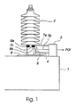
- Figure 1 shows part of an electric power transformer 1 with a high-voltage bushing 2.
- a signal matching unit 3 is located on the transformer close to the high-voltage bushing and is connected, by means of a conductor 4, to a capacitive test tap 5.
- An inductive sensor 6, which will be described in greater detail below and which comprises two coils 6a, 6b, is also connected by means of conductors 7a, 7b to the signal matching unit. The sensor is arranged at the lower part of the high-voltage bushing immediately above a flange 8, through which the bushing passes into the transformer.
- the inductive sensor is based on the principle of a Rogowski coil but has been modified to obtain sufficient sensitivity and to facilitate installation and manufacture.
- the inductive sensor thus comprises ( Figures 9a, 9b, 9c ) two relatively short coils 6a, 6b, which are mutually series-connected by means of a conductor 7c.
- Each one of the coils, of which Figure 9a shows one, is wound onto a magnetic core 61a, 61b and the two coils are then connected in series with each other.
- Figure 9a shows a design of the coils and Figures 9b and 9c show a preferred location thereof.
- the two coils are mounted on the high-voltage bushing opposite to each other and are attached thereto, for example by gluing.
- the capacitive test tap of the high-voltage bushing is used.
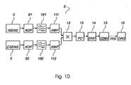
- the signal matching unit ( Figure 10 ) is supplied with signals from respectively the inductive sensor 6 and from the capacitive test tap 5.
- the signal matching unit comprises two matching circuits 91, 92 for matching of the respective signals to each other's level and for amplification to a suitable signal level.
- the matching is performed by means of passive circuit elements with resistive, inductive, and capacitive impedances.
- Each of the output signals from the respective matching circuits is then supplied to a different bandpass filter 101, 102, which bandpass filters are tuned to the resonance frequency of the coils.
- the resonance frequency of the coils has been chosen to attain the best signal/noise ratio.
- the output signals from the respective bandpass filter are each supplied to an amplification means 111, 112, and the output signals therefrom are supplied to a multiplying means 12, in which the two signals are multiplied by each other.
- the output signal from the multiplier is now either positive or negative, depending on the origin of the discharge.
- the measurement principle is based on determining the polarity of a partial discharge with the aid of the output signal from the capacitive test tap whereas the direction of the current pulse associated with the discharge is determined with the aid of the output signal from the inductive sensor.
- the direction of the power flux of the discharge may be determined, and the output signal from the multiplying means is either positive or negative depending on where the discharge is generated. Discharges outside the transformer will correspond to positive signals, or vice versa, depending on how the coils in the inductive sensor are wound.
- the boundary line for this polarity reversal is the location on which the coils are applied, usually at the base of the bushing.
- the output signals from the multiplying means are supplied to a peak value detector 13, which only forwards positive signals.
- the output signal from the peak value detector is then supplied to an envelope circuit 14, which extends the decay time for its input signal.
- the amplitude of the output signal from the envelope circuit is related to the level of the internal discharge such that an increasing level of internal discharge results in an increasing value of the output signal of the envelope circuit.
- This output signal is supplied to a data acquisition system 16, arranged outside the signal matching unit, via a conversion circuit 15 which converts the output signal from the envelope circuit to a corresponding direct current PDI.
- the direct current PDI from the signal matching unit to the data acquisition system will thus correspond to the amount of internal discharge.
- the direct current is compared in the data acquisition unit with a preselected alarm level, programmed into the data acquisition unit, and an alarm is considered to be an indication of a abnormal state in the power transformer and that a more careful investigation should be made. Further investigations may, for example, be made with some of the diagnostic tools which are available; see, for example, Proceedings of the 1995 Swiss Power Tech Conference. C. Bengtsson: "Status and trends in Transformer Monitoring ", for an overview.
- the sensor system described may also improve, for example, PRPDA diagnostic measurements.
- the described direction-sensitive two-sensor system for sensing partial discharges has, during laboratory tests, shown a good capacity to distinguish internal discharges from external ones. This has also been verified during a field measurement carried out on a 100 MVA transformer.
- Figures 2-4 and 5-8 show typical signal shapes for output signals from the signal matching unit with the time t plotted on the horizontal axis and the amplitude PDI of the output signal on the vertical axis.
- Figures 2-3 show signal shapes observed in a test room environment with the sensors applied to a separate high-voltage bushing provided with a capacitive test tap.
- the discharges were simulated by supplying both positive and negative calibration pulses according to IEC Publication 270 to both sides of the bushing.
- Figure 2 shows the output signal in case of an externally applied calibration pulse
- Figure 3 shows the output signal in case of an internally applied calibration pulse.
- the system can clearly distinguish internal discharges from external ones in that external discharges result in a negative output signal and an internal discharge results in a positive output signal.
- Figure 4 shows signal shapes observed with the sensors applied to a laboratory transformer. External disturbances are simulated by means of a point plane gap connected to a high-voltage level and the figure shows an external disturbance (corona) both for half a period (lower horizontal axis) and with a higher resolution with respect to time (upper horizontal axis).
- Figures 5-8 show signal shapes observed in the field with the sensors applied to a 130/50 kV 100 MVA transformer provided with capacitive test taps on the high-voltage bushings. The transformer had not previously shown any indication of partial discharges.
- Figure 5 shows signal shapes observed with the sensors applied to phase 1 and phase 2 and with an external calibration pulse applied to phase 2. As is clear from the figure, an output signal with a negative polarity (lower horizontal axis) is observed. Because of the capacitive coupling between the phases, the calibration pulse results in an output signal also in phase 1 (upper horizontal axis).
- Figures 6-8 show signal shapes observed with the transformer connected to a 130 kV line and with the 50 kV side open.
- Figure 6 shows, with a high resolution with respect to time, typical signal shapes observed in phase 2 with a number of discharges.
- Figure 7 shows typical signal shapes observed over a full period, in phase 2 (upper horizontal axis) and phase 1 (lower horizontal axis).
- Figure 8 shows typical signal shapes observed during operation of the tap changer of the transformer.
- the positive parts of the output signal indicate internal transients.
- the signals caused by the tap-changer operation are larger, by several orders of magnitude, than those signals from partial discharges which the device is to sense. For this reason, the amplifiers are saturated and an associated phase shift occurs. This is the reason for the negative values of the output signal in Figure 8 .
- Figures 5-8 show that the system is able to distinguish between internal and external discharges also under field conditions.
- the inductive sensor need not necessarily be designed in the form of two series-connected coils but may be designed as one single coil.
- the capacitive test taps of the high-voltage bushings of the transformer may preferably be used, but also other sensors for sensing of the electric field associated with the partial discharge may be used.
- test results together with the simplicity, the low cost and the simplicity of installing the sensor system show that the invention is suitable for direct-connected monitoring of both new and existing power transformers.
Landscapes
- Physics & Mathematics (AREA)
- General Physics & Mathematics (AREA)
- Engineering & Computer Science (AREA)
- Power Engineering (AREA)
- Testing Relating To Insulation (AREA)
- Testing Of Short-Circuits, Discontinuities, Leakage, Or Incorrect Line Connections (AREA)
- Protection Of Transformers (AREA)
- Housings And Mounting Of Transformers (AREA)
- Gas-Insulated Switchgears (AREA)
- Testing Electric Properties And Detecting Electric Faults (AREA)
Applications Claiming Priority (3)
| Application Number | Priority Date | Filing Date | Title |
|---|---|---|---|
| SE9501664 | 1995-05-02 | ||
| SE9501664A SE515387C2 (sv) | 1995-05-02 | 1995-05-02 | Övervakning av interna partiella urladdningar i en krafttransformator |
| PCT/SE1996/000558 WO1996035128A1 (en) | 1995-05-02 | 1996-04-29 | Monitoring of internal partial discharges on a power transformer |
Publications (2)
| Publication Number | Publication Date |
|---|---|
| EP0769150A1 EP0769150A1 (en) | 1997-04-23 |
| EP0769150B1 true EP0769150B1 (en) | 2008-03-12 |
Family
ID=20398202
Family Applications (1)
| Application Number | Title | Priority Date | Filing Date |
|---|---|---|---|
| EP96913760A Expired - Lifetime EP0769150B1 (en) | 1995-05-02 | 1996-04-29 | Monitoring of internal partial discharges on a power transformer |
Country Status (16)
| Country | Link |
|---|---|
| US (1) | US5903158A (cs) |
| EP (1) | EP0769150B1 (cs) |
| JP (1) | JPH10505913A (cs) |
| CN (1) | CN1078709C (cs) |
| AT (1) | ATE389186T1 (cs) |
| AU (1) | AU695413B2 (cs) |
| BR (1) | BR9606349A (cs) |
| CA (1) | CA2192856C (cs) |
| CZ (1) | CZ384996A3 (cs) |
| DE (1) | DE69637461T2 (cs) |
| EA (1) | EA000019B1 (cs) |
| ES (1) | ES2302335T3 (cs) |
| NO (1) | NO965625L (cs) |
| PL (1) | PL317610A1 (cs) |
| SE (1) | SE515387C2 (cs) |
| WO (1) | WO1996035128A1 (cs) |
Cited By (2)
| Publication number | Priority date | Publication date | Assignee | Title |
|---|---|---|---|---|
| CN103513132A (zh) * | 2013-09-23 | 2014-01-15 | 国家电网公司 | 输变电系统设备状态仿真装置 |
| CN106803639B (zh) * | 2016-12-07 | 2018-06-26 | 西北核技术研究所 | 兆伏低抖动多级电晕开关 |
Families Citing this family (59)
| Publication number | Priority date | Publication date | Assignee | Title |
|---|---|---|---|---|
| SE508154C2 (sv) * | 1996-10-16 | 1998-09-07 | Abb Research Ltd | Anordning för övervakning av partiella urladdningar i en elektrisk högspänningsapparat eller högspänningsutrustning |
| SE508160C2 (sv) * | 1997-03-10 | 1998-09-07 | Abb Research Ltd | Anordning för avkänning av elektriska urladdningar i ett provobjekt med två elektriska anslutningsledare |
| US6420879B2 (en) * | 1998-02-02 | 2002-07-16 | Massachusetts Institute Of Technology | System and method for measurement of partial discharge signals in high voltage apparatus |
| AUPP195898A0 (en) * | 1998-02-23 | 1998-03-19 | University Of Sydney, The | High voltage power monitoring apparatus |
| DE19832387A1 (de) * | 1998-07-18 | 2000-01-20 | Asea Brown Boveri | Verfahren zum Feststellen von Einbau- und/oder Kalibrierungsfehlern einer Mehrzahl von Signalauskopplungseinheiten eines oder mehrerer Teilentladungsmeßsysteme |
| US6433557B1 (en) | 2000-12-21 | 2002-08-13 | Eaton Corporation | Electrical system with capacitance tap and sensor for on-line monitoring the state of high-voltage insulation and remote monitoring device |
| US6504382B2 (en) | 2000-12-21 | 2003-01-07 | Eaton Corporation | Electrical system with a stress shield system for partial discharge on-line monitoring of the state of high-voltage insulation |
| US6489782B1 (en) | 2000-12-21 | 2002-12-03 | Eaton Corporation | Electrical system with a stand-off insulator-sensor for on-line partial discharge monitoring of the state of high-voltage insulation |
| AU2003267842A1 (en) * | 2002-10-10 | 2004-05-04 | Hanyang Hak Won Co., Ltd. | Hybrid type sensor for detecting high frequency partial discharge |
| US6833713B2 (en) * | 2003-01-31 | 2004-12-21 | Delphi Technologies, Inc. | Smart wire harness for an electrical circuit |
| EP1623240B1 (de) * | 2003-05-09 | 2008-04-09 | Siemens Aktiengesellschaft | Messeinrichtung und verfahren zur ortung einer teilentladung |
| GB2422967B (en) * | 2003-10-22 | 2007-06-06 | Fujikura Ltd | Insulation degradation diagnostic device |
| BRPI0502384A (pt) * | 2005-06-21 | 2007-02-06 | Siemens Ltda | sistema e método de monitoração e controle da condição de operação de um transformador de potência |
| ITRM20080304A1 (it) * | 2008-06-11 | 2009-12-12 | Univ Palermo | Dispositivo portatile per la rilevazione di scariche parziali |
| ATE526588T1 (de) * | 2009-08-07 | 2011-10-15 | Omicron Electronics Gmbh | System zur überwachung eines transformators |
| ES2365779B1 (es) * | 2009-09-25 | 2012-09-04 | Instituto De Tecnología Eléctrica Ite | Sistema de medida de descargas parciales en líneas eléctricas. |
| US8497688B2 (en) * | 2010-04-14 | 2013-07-30 | Electric Power Research Institute, Inc. | Non-contact arc detection apparatus and method |
| CN101900780B (zh) * | 2010-04-20 | 2012-06-27 | 浙江科技学院 | 一种开关柜在柜式母线局放实时检测系统 |
| RU2434236C1 (ru) * | 2010-07-27 | 2011-11-20 | Вадим Анатольевич Шахнин | Способ диагностики высоковольтного оборудования |
| EP2466324B1 (en) * | 2010-12-15 | 2013-07-24 | ABB Technology AG | Combined measuring and detection system |
| CN102680862A (zh) * | 2011-03-15 | 2012-09-19 | 华东电力试验研究院有限公司 | 并联电容器局部放电在线监测装置及方法 |
| KR101654382B1 (ko) * | 2011-10-31 | 2016-09-06 | 한국전력공사 | 절연역률 측정 장치 및 방법 |
| FR2987900B1 (fr) * | 2012-03-09 | 2015-07-31 | Alstom Technology Ltd | Procede de reconnaissance de decharges partielles emises a l'interieur et a l'exterieur d'un appareil electrique |
| CN102955145B (zh) * | 2012-10-26 | 2015-02-04 | 湖北省电力公司电力科学研究院 | 变压器运行状态仿真监测系统 |
| US9482699B2 (en) * | 2013-06-18 | 2016-11-01 | Advanced Power Technologies, Llc | Method and apparatus for monitoring high voltage bushings safely |
| KR101496442B1 (ko) * | 2013-07-01 | 2015-02-27 | 한빛이디에스(주) | 케이블 부분방전 진단 장치 |
| RU2536795C1 (ru) * | 2013-08-06 | 2014-12-27 | Федеральное государственное бюджетное образовательное учреждение высшего профессионального образования "Владимирский государственный университет имени Александра Григорьевича и Николая Григорьевича Столетовых" (ВлГУ) | Способ диагностики высоковольтного оборудования по параметрам частичных разрядов |
| CN103543391B (zh) * | 2013-09-29 | 2016-05-25 | 广西电网公司电力科学研究院 | 一种直流局部放电源检测与识别装置 |
| US20150098161A1 (en) * | 2013-10-09 | 2015-04-09 | Hamilton Sundstrand Corporation | Integrated corona fault detection |
| RU2552842C2 (ru) * | 2013-10-17 | 2015-06-10 | Федеральное государственное бюджетное образовательное учреждение высшего профессионального образования "Нижегородский государственный технический университет им. Р.Е. Алексеева", НГТУ | Цифровая трансформаторная подстанция |
| CN103558522A (zh) * | 2013-11-02 | 2014-02-05 | 国家电网公司 | 冲击电压下变压器局部放电检测方法 |
| CN103558521A (zh) * | 2013-11-02 | 2014-02-05 | 国家电网公司 | 冲击电压下变压器局部放电检测装置 |
| CN103713244B (zh) * | 2013-12-30 | 2016-08-17 | 国家电网公司 | 一种用于配电电缆局部放电的带电检测方法 |
| WO2015178975A2 (en) | 2014-02-13 | 2015-11-26 | Micatu Inc. | An optical sensor system and methods of use thereof |
| JP6331521B2 (ja) * | 2014-03-14 | 2018-05-30 | 日新電機株式会社 | 部分放電監視装置および部分放電監視システム |
| WO2015172849A1 (en) * | 2014-05-16 | 2015-11-19 | Prysmian S.P.A. | A partial discharge acquisition system comprising a capacitive coupling electric field sensor |
| US9753080B2 (en) | 2014-12-09 | 2017-09-05 | Rosemount Inc. | Partial discharge detection system |
| US10215621B2 (en) | 2015-04-17 | 2019-02-26 | Micatu Inc. | Enhanced optical condition monitoring system for power transformer and method for operating power transformer |
| NZ738108A (en) * | 2015-06-05 | 2020-03-27 | Ormazabal Prot & Automation S L U | System for detecting and indicating partial discharges and voltage |
| US10401169B2 (en) | 2015-10-09 | 2019-09-03 | Micatu Inc. | Enhanced power transmission tower condition monitoring system for overhead power systems |
| RU2650894C1 (ru) * | 2016-10-27 | 2018-04-18 | ПАО "Московская объединённая электросетевая компания" (ПАО "МОЭСК") | Автоматизированная система мониторинга, защиты и управления оборудованием электрической подстанции |
| CN109073704A (zh) | 2017-03-02 | 2018-12-21 | 罗斯蒙特公司 | 用于局部放电的趋势函数 |
| US11067639B2 (en) | 2017-11-03 | 2021-07-20 | Rosemount Inc. | Trending functions for predicting the health of electric power assets |
| US10794736B2 (en) | 2018-03-15 | 2020-10-06 | Rosemount Inc. | Elimination of floating potential when mounting wireless sensors to insulated conductors |
| US11181570B2 (en) | 2018-06-15 | 2021-11-23 | Rosemount Inc. | Partial discharge synthesizer |
| US10833531B2 (en) | 2018-10-02 | 2020-11-10 | Rosemount Inc. | Electric power generation or distribution asset monitoring |
| CN109375013A (zh) * | 2018-10-19 | 2019-02-22 | 江苏盛久变压器有限公司 | 一种变压器的测试系统 |
| RU2700368C1 (ru) * | 2018-12-26 | 2019-09-16 | федеральное государственное бюджетное образовательное учреждение высшего образования "Ивановский государственный энергетический университет имени В.И. Ленина" (ИГЭУ) | Способ определения технического состояния цифрового трансформатора по параметрам частичных разрядов в изоляции |
| RU2700369C1 (ru) * | 2018-12-26 | 2019-09-16 | федеральное государственное бюджетное образовательное учреждение высшего образования "Ивановский государственный энергетический университет имени В.И. Ленина" (ИГЭУ) | Устройство контроля технического состояния цифрового трансформатора по параметрам частичных разрядов в изоляции |
| RU195528U1 (ru) * | 2019-05-29 | 2020-01-30 | ООО "Оптиметрик" | Высоковольтное многофункциональное измерительное устройство |
| RU2724991C1 (ru) * | 2019-09-03 | 2020-06-29 | федеральное государственное бюджетное образовательное учреждение высшего образования "Ивановский государственный энергетический университет имени В.И. Ленина" (ИГЭУ) | Способ определения технического состояния изоляции цифрового трансформатора по параметрам частичных разрядов |
| US11313895B2 (en) | 2019-09-24 | 2022-04-26 | Rosemount Inc. | Antenna connectivity with shielded twisted pair cable |
| RU2727525C1 (ru) * | 2019-12-02 | 2020-07-22 | Общество с ограниченной ответственностью Научно-производственное объединение "Цифровые измерительные трансформаторы" (ООО НПО "ЦИТ") | Способ мониторинга, защиты и управления оборудованием электрической подстанции |
| RU2727526C1 (ru) * | 2019-12-02 | 2020-07-22 | Общество с ограниченной ответственностью Научно-производственное объединение "Цифровые измерительные трансформаторы" (ООО НПО "ЦИТ") | Система мониторинга, защиты и управления оборудованием электрической подстанции |
| PL3839524T3 (pl) * | 2019-12-16 | 2026-03-23 | E.On Se | Sposób, urządzenie i układ do monitorowania transformatora rozprzestrzenia energii |
| AT523525B1 (de) * | 2020-03-31 | 2021-09-15 | Baur Gmbh | Elektrische Schaltungsanordnung |
| CN111751676B (zh) * | 2020-05-26 | 2024-09-10 | 南方电网科学研究院有限责任公司 | 能区分变压器和套管局部放电信号的检测系统及方法 |
| RU2734110C1 (ru) * | 2020-07-20 | 2020-10-13 | Федеральное государственное бюджетное научное учреждение "Федеральный научный агроинженерный центр ВИМ" (ФГБНУ ФНАЦ ВИМ) | Цифровая трансформаторная подстанция с активно-адаптивной системой управления |
| CN112731075B (zh) * | 2020-12-17 | 2022-04-29 | 国网电力科学研究院武汉南瑞有限责任公司 | 一种传感器内置一体化结构的智能套管 |
Family Cites Families (6)
| Publication number | Priority date | Publication date | Assignee | Title |
|---|---|---|---|---|
| US3488591A (en) * | 1965-03-11 | 1970-01-06 | Westinghouse Electric Corp | Voltage and current responsive apparatus employing molecular function block sensors sensitive to electric and magnetic fields for use in a high voltage bushing |
| US3430136A (en) * | 1965-12-21 | 1969-02-25 | Gen Electric | Test equipment for identification and location of electrical faults in fluid-filled electric apparatus |
| EP0241764B1 (de) * | 1986-04-14 | 1990-08-01 | Siemens Aktiengesellschaft | Verfahren und Vorrichtungen zur Erkennung und Lokalisierung von Schäden in elektrischen Anlagen |
| CA1264183A (en) * | 1986-12-15 | 1990-01-02 | Wagih Z. Fam | Poynting vector probe for measuring electric power |
| JPH0738011B2 (ja) * | 1988-05-16 | 1995-04-26 | 株式会社日立製作所 | 高圧電力機器の異常診断システム |
| US5185685A (en) * | 1991-03-28 | 1993-02-09 | Eaton Corporation | Field sensing arc detection |
-
1995
- 1995-05-02 SE SE9501664A patent/SE515387C2/sv not_active IP Right Cessation
-
1996
- 1996-04-29 PL PL96317610A patent/PL317610A1/xx unknown
- 1996-04-29 EP EP96913760A patent/EP0769150B1/en not_active Expired - Lifetime
- 1996-04-29 AU AU56613/96A patent/AU695413B2/en not_active Ceased
- 1996-04-29 US US08/750,592 patent/US5903158A/en not_active Expired - Lifetime
- 1996-04-29 JP JP8533229A patent/JPH10505913A/ja active Pending
- 1996-04-29 DE DE69637461T patent/DE69637461T2/de not_active Expired - Lifetime
- 1996-04-29 ES ES96913760T patent/ES2302335T3/es not_active Expired - Lifetime
- 1996-04-29 EA EA199700012A patent/EA000019B1/ru not_active IP Right Cessation
- 1996-04-29 CN CN96190440A patent/CN1078709C/zh not_active Expired - Fee Related
- 1996-04-29 WO PCT/SE1996/000558 patent/WO1996035128A1/en not_active Ceased
- 1996-04-29 CZ CZ963849A patent/CZ384996A3/cs unknown
- 1996-04-29 AT AT96913760T patent/ATE389186T1/de not_active IP Right Cessation
- 1996-04-29 CA CA002192856A patent/CA2192856C/en not_active Expired - Fee Related
- 1996-04-29 BR BR9606349A patent/BR9606349A/pt not_active Application Discontinuation
- 1996-12-30 NO NO965625A patent/NO965625L/no unknown
Cited By (3)
| Publication number | Priority date | Publication date | Assignee | Title |
|---|---|---|---|---|
| CN103513132A (zh) * | 2013-09-23 | 2014-01-15 | 国家电网公司 | 输变电系统设备状态仿真装置 |
| CN103513132B (zh) * | 2013-09-23 | 2016-10-19 | 国家电网公司 | 输变电系统设备状态仿真装置 |
| CN106803639B (zh) * | 2016-12-07 | 2018-06-26 | 西北核技术研究所 | 兆伏低抖动多级电晕开关 |
Also Published As
| Publication number | Publication date |
|---|---|
| JPH10505913A (ja) | 1998-06-09 |
| ATE389186T1 (de) | 2008-03-15 |
| AU695413B2 (en) | 1998-08-13 |
| CN1078709C (zh) | 2002-01-30 |
| AU5661396A (en) | 1996-11-21 |
| CN1152355A (zh) | 1997-06-18 |
| SE515387C2 (sv) | 2001-07-23 |
| DE69637461T2 (de) | 2009-04-02 |
| WO1996035128A1 (en) | 1996-11-07 |
| NO965625D0 (no) | 1996-12-30 |
| CA2192856A1 (en) | 1996-11-07 |
| ES2302335T3 (es) | 2008-07-01 |
| NO965625L (no) | 1996-12-30 |
| SE9501664D0 (sv) | 1995-05-02 |
| EA199700012A1 (ru) | 1997-09-30 |
| EP0769150A1 (en) | 1997-04-23 |
| SE9501664L (sv) | 1996-11-03 |
| PL317610A1 (en) | 1997-04-14 |
| CZ384996A3 (en) | 1997-03-12 |
| CA2192856C (en) | 2000-09-19 |
| EA000019B1 (ru) | 1997-12-30 |
| BR9606349A (pt) | 1997-12-23 |
| DE69637461D1 (de) | 2008-04-24 |
| US5903158A (en) | 1999-05-11 |
Similar Documents
| Publication | Publication Date | Title |
|---|---|---|
| EP0769150B1 (en) | Monitoring of internal partial discharges on a power transformer | |
| EP0792465B1 (en) | A device for sensing of electric discharges in a test object | |
| Wu et al. | A new testing method for the diagnosis of winding faults in transformer | |
| EP0544646B1 (en) | Apparatus for assessing insulation conditions | |
| US8219335B2 (en) | Electric winding displacement detection method and apparatus | |
| CN101208845B (zh) | 故障电流分析器和具有故障电流检测功能的装置 | |
| Tenbohlen et al. | Enhanced diagnosis of power transformers using on-and off-line methods: Results, examples and future trends | |
| US6853939B2 (en) | Systems and methods for multiple winding impulse frequency response analysis test | |
| US6466034B1 (en) | Transformer winding movement detection by high frequency internal response analysis | |
| Farag et al. | On-line partial discharge calibration and monitoring for power transformers | |
| Kheirmand et al. | Advances in online monitoring and localization of partial discharges in large rotating machines | |
| CN115711736A (zh) | 设备状态检测的方法、装置、电子设备及存储介质 | |
| CN118829895A (zh) | 设备诊断装置和设备诊断系统 | |
| Kheirmand et al. | New practices for partial discharge detection and localization in large rotating machines | |
| Bartnikas | Partial discharge diagnostics: a utility perspective | |
| CN111487463B (zh) | 一种间谐波检测系统及方法 | |
| Wang et al. | PD monitor system for power generators | |
| Timperley et al. | Electromagnetic interference data collection from bus coupler capacitors | |
| Toscani et al. | A novel modular data acquisition system for distributed monitoring of partial discharge in industrial drives | |
| Zeng et al. | Research on the Analytical-Model-Based Setting Method for Leakage Magnetic-Field Differential Protection for Transformer Early Fault | |
| Badicu et al. | A Versatile System for PD Diagnostics | |
| CN117168291A (zh) | 变压器绕组变形的测试方法 | |
| CN115436683A (zh) | 一种电流检测装置及方法 | |
| CN117110800A (zh) | 一种开关柜局部放电与干扰脉冲信号的判别方法 | |
| JPS62153777A (ja) | 油入電器の部分放電監視方法 |
Legal Events
| Date | Code | Title | Description |
|---|---|---|---|
| PUAI | Public reference made under article 153(3) epc to a published international application that has entered the european phase |
Free format text: ORIGINAL CODE: 0009012 |
|
| 17P | Request for examination filed |
Effective date: 19961212 |
|
| AK | Designated contracting states |
Kind code of ref document: A1 Designated state(s): AT BE CH DE DK ES FI FR GB GR IE IT LI NL PT SE |
|
| AX | Request for extension of the european patent |
Free format text: SI PAYMENT 961212 |
|
| 17Q | First examination report despatched |
Effective date: 20060918 |
|
| GRAP | Despatch of communication of intention to grant a patent |
Free format text: ORIGINAL CODE: EPIDOSNIGR1 |
|
| RBV | Designated contracting states (corrected) |
Designated state(s): AT BE CH DE DK ES FI FR GB GR IE IT LI NL PT SE |
|
| GRAS | Grant fee paid |
Free format text: ORIGINAL CODE: EPIDOSNIGR3 |
|
| GRAA | (expected) grant |
Free format text: ORIGINAL CODE: 0009210 |
|
| AK | Designated contracting states |
Kind code of ref document: B1 Designated state(s): AT BE CH DE DK ES FI FR GB GR IE IT LI NL PT SE |
|
| AX | Request for extension of the european patent |
Extension state: SI |
|
| REG | Reference to a national code |
Ref country code: GB Ref legal event code: FG4D |
|
| REG | Reference to a national code |
Ref country code: CH Ref legal event code: EP |
|
| REG | Reference to a national code |
Ref country code: IE Ref legal event code: FG4D |
|
| REF | Corresponds to: |
Ref document number: 69637461 Country of ref document: DE Date of ref document: 20080424 Kind code of ref document: P |
|
| REG | Reference to a national code |
Ref country code: ES Ref legal event code: FG2A Ref document number: 2302335 Country of ref document: ES Kind code of ref document: T3 |
|
| PG25 | Lapsed in a contracting state [announced via postgrant information from national office to epo] |
Ref country code: FI Free format text: LAPSE BECAUSE OF FAILURE TO SUBMIT A TRANSLATION OF THE DESCRIPTION OR TO PAY THE FEE WITHIN THE PRESCRIBED TIME-LIMIT Effective date: 20080312 |
|
| PG25 | Lapsed in a contracting state [announced via postgrant information from national office to epo] |
Ref country code: AT Free format text: LAPSE BECAUSE OF FAILURE TO SUBMIT A TRANSLATION OF THE DESCRIPTION OR TO PAY THE FEE WITHIN THE PRESCRIBED TIME-LIMIT Effective date: 20080312 |
|
| NLV1 | Nl: lapsed or annulled due to failure to fulfill the requirements of art. 29p and 29m of the patents act | ||
| PG25 | Lapsed in a contracting state [announced via postgrant information from national office to epo] |
Ref country code: BE Free format text: LAPSE BECAUSE OF FAILURE TO SUBMIT A TRANSLATION OF THE DESCRIPTION OR TO PAY THE FEE WITHIN THE PRESCRIBED TIME-LIMIT Effective date: 20080312 |
|
| PG25 | Lapsed in a contracting state [announced via postgrant information from national office to epo] |
Ref country code: SE Free format text: LAPSE BECAUSE OF FAILURE TO SUBMIT A TRANSLATION OF THE DESCRIPTION OR TO PAY THE FEE WITHIN THE PRESCRIBED TIME-LIMIT Effective date: 20080612 Ref country code: PT Free format text: LAPSE BECAUSE OF FAILURE TO SUBMIT A TRANSLATION OF THE DESCRIPTION OR TO PAY THE FEE WITHIN THE PRESCRIBED TIME-LIMIT Effective date: 20080814 |
|
| PG25 | Lapsed in a contracting state [announced via postgrant information from national office to epo] |
Ref country code: NL Free format text: LAPSE BECAUSE OF FAILURE TO SUBMIT A TRANSLATION OF THE DESCRIPTION OR TO PAY THE FEE WITHIN THE PRESCRIBED TIME-LIMIT Effective date: 20080312 |
|
| REG | Reference to a national code |
Ref country code: CH Ref legal event code: PL |
|
| EN | Fr: translation not filed | ||
| PLBE | No opposition filed within time limit |
Free format text: ORIGINAL CODE: 0009261 |
|
| STAA | Information on the status of an ep patent application or granted ep patent |
Free format text: STATUS: NO OPPOSITION FILED WITHIN TIME LIMIT |
|
| PG25 | Lapsed in a contracting state [announced via postgrant information from national office to epo] |
Ref country code: LI Free format text: LAPSE BECAUSE OF NON-PAYMENT OF DUE FEES Effective date: 20080430 Ref country code: DK Free format text: LAPSE BECAUSE OF FAILURE TO SUBMIT A TRANSLATION OF THE DESCRIPTION OR TO PAY THE FEE WITHIN THE PRESCRIBED TIME-LIMIT Effective date: 20080312 Ref country code: CH Free format text: LAPSE BECAUSE OF NON-PAYMENT OF DUE FEES Effective date: 20080430 |
|
| 26N | No opposition filed |
Effective date: 20081215 |
|
| PG25 | Lapsed in a contracting state [announced via postgrant information from national office to epo] |
Ref country code: IE Free format text: LAPSE BECAUSE OF NON-PAYMENT OF DUE FEES Effective date: 20080429 Ref country code: FR Free format text: LAPSE BECAUSE OF FAILURE TO SUBMIT A TRANSLATION OF THE DESCRIPTION OR TO PAY THE FEE WITHIN THE PRESCRIBED TIME-LIMIT Effective date: 20090102 |
|
| PG25 | Lapsed in a contracting state [announced via postgrant information from national office to epo] |
Ref country code: GR Free format text: LAPSE BECAUSE OF FAILURE TO SUBMIT A TRANSLATION OF THE DESCRIPTION OR TO PAY THE FEE WITHIN THE PRESCRIBED TIME-LIMIT Effective date: 20080613 |
|
| PGFP | Annual fee paid to national office [announced via postgrant information from national office to epo] |
Ref country code: GB Payment date: 20140422 Year of fee payment: 19 |
|
| PGFP | Annual fee paid to national office [announced via postgrant information from national office to epo] |
Ref country code: IT Payment date: 20140430 Year of fee payment: 19 Ref country code: DE Payment date: 20140418 Year of fee payment: 19 Ref country code: ES Payment date: 20140428 Year of fee payment: 19 |
|
| REG | Reference to a national code |
Ref country code: DE Ref legal event code: R119 Ref document number: 69637461 Country of ref document: DE |
|
| GBPC | Gb: european patent ceased through non-payment of renewal fee |
Effective date: 20150429 |
|
| PG25 | Lapsed in a contracting state [announced via postgrant information from national office to epo] |
Ref country code: DE Free format text: LAPSE BECAUSE OF NON-PAYMENT OF DUE FEES Effective date: 20151103 Ref country code: GB Free format text: LAPSE BECAUSE OF NON-PAYMENT OF DUE FEES Effective date: 20150429 Ref country code: IT Free format text: LAPSE BECAUSE OF NON-PAYMENT OF DUE FEES Effective date: 20150429 |
|
| REG | Reference to a national code |
Ref country code: ES Ref legal event code: FD2A Effective date: 20160526 |
|
| PG25 | Lapsed in a contracting state [announced via postgrant information from national office to epo] |
Ref country code: ES Free format text: LAPSE BECAUSE OF NON-PAYMENT OF DUE FEES Effective date: 20150430 |