EP0768547B1 - Jack receptacle for an optical connector - Google Patents
Jack receptacle for an optical connector Download PDFInfo
- Publication number
- EP0768547B1 EP0768547B1 EP96307197A EP96307197A EP0768547B1 EP 0768547 B1 EP0768547 B1 EP 0768547B1 EP 96307197 A EP96307197 A EP 96307197A EP 96307197 A EP96307197 A EP 96307197A EP 0768547 B1 EP0768547 B1 EP 0768547B1
- Authority
- EP
- European Patent Office
- Prior art keywords
- receptacle
- connector
- panel
- jack
- cavity
- Prior art date
- Legal status (The legal status is an assumption and is not a legal conclusion. Google has not performed a legal analysis and makes no representation as to the accuracy of the status listed.)
- Expired - Lifetime
Links
- 230000003287 optical effect Effects 0.000 title claims description 42
- 230000013011 mating Effects 0.000 claims description 6
- 239000012815 thermoplastic material Substances 0.000 claims description 4
- 239000004417 polycarbonate Substances 0.000 claims description 3
- 229920000515 polycarbonate Polymers 0.000 claims description 3
- 230000000295 complement effect Effects 0.000 claims 1
- 239000013307 optical fiber Substances 0.000 description 20
- 238000003780 insertion Methods 0.000 description 9
- 230000037431 insertion Effects 0.000 description 9
- 238000013461 design Methods 0.000 description 7
- 239000000835 fiber Substances 0.000 description 6
- 238000000465 moulding Methods 0.000 description 5
- 238000004891 communication Methods 0.000 description 3
- 238000012986 modification Methods 0.000 description 3
- 230000004048 modification Effects 0.000 description 3
- 239000004033 plastic Substances 0.000 description 3
- 229920003023 plastic Polymers 0.000 description 3
- 239000000853 adhesive Substances 0.000 description 2
- 230000001070 adhesive effect Effects 0.000 description 2
- 239000000919 ceramic Substances 0.000 description 2
- 230000006835 compression Effects 0.000 description 2
- 238000007906 compression Methods 0.000 description 2
- 238000010276 construction Methods 0.000 description 2
- 239000011521 glass Substances 0.000 description 2
- 238000005304 joining Methods 0.000 description 2
- 239000000463 material Substances 0.000 description 2
- 239000002184 metal Substances 0.000 description 2
- 229910052751 metal Inorganic materials 0.000 description 2
- 238000000034 method Methods 0.000 description 2
- 230000002787 reinforcement Effects 0.000 description 2
- RYGMFSIKBFXOCR-UHFFFAOYSA-N Copper Chemical compound [Cu] RYGMFSIKBFXOCR-UHFFFAOYSA-N 0.000 description 1
- 230000001154 acute effect Effects 0.000 description 1
- 239000011248 coating agent Substances 0.000 description 1
- 238000000576 coating method Methods 0.000 description 1
- 229910052802 copper Inorganic materials 0.000 description 1
- 239000010949 copper Substances 0.000 description 1
- 230000008878 coupling Effects 0.000 description 1
- 238000010168 coupling process Methods 0.000 description 1
- 238000005859 coupling reaction Methods 0.000 description 1
- 230000000881 depressing effect Effects 0.000 description 1
- 230000000994 depressogenic effect Effects 0.000 description 1
- 239000002360 explosive Substances 0.000 description 1
- 238000007667 floating Methods 0.000 description 1
- 238000009434 installation Methods 0.000 description 1
- 238000004519 manufacturing process Methods 0.000 description 1
- 238000012856 packing Methods 0.000 description 1
- 239000003973 paint Substances 0.000 description 1
- 230000010287 polarization Effects 0.000 description 1
- 239000004800 polyvinyl chloride Substances 0.000 description 1
- 230000008707 rearrangement Effects 0.000 description 1
- 230000000717 retained effect Effects 0.000 description 1
- 238000012360 testing method Methods 0.000 description 1
- 238000003466 welding Methods 0.000 description 1
Images


Classifications
-
- G—PHYSICS
- G02—OPTICS
- G02B—OPTICAL ELEMENTS, SYSTEMS OR APPARATUS
- G02B6/00—Light guides; Structural details of arrangements comprising light guides and other optical elements, e.g. couplings
- G02B6/24—Coupling light guides
- G02B6/36—Mechanical coupling means
-
- G—PHYSICS
- G02—OPTICS
- G02B—OPTICAL ELEMENTS, SYSTEMS OR APPARATUS
- G02B6/00—Light guides; Structural details of arrangements comprising light guides and other optical elements, e.g. couplings
- G02B6/24—Coupling light guides
- G02B6/36—Mechanical coupling means
- G02B6/38—Mechanical coupling means having fibre to fibre mating means
- G02B6/3807—Dismountable connectors, i.e. comprising plugs
- G02B6/389—Dismountable connectors, i.e. comprising plugs characterised by the method of fastening connecting plugs and sockets, e.g. screw- or nut-lock, snap-in, bayonet type
- G02B6/3893—Push-pull type, e.g. snap-in, push-on
-
- G—PHYSICS
- G02—OPTICS
- G02B—OPTICAL ELEMENTS, SYSTEMS OR APPARATUS
- G02B6/00—Light guides; Structural details of arrangements comprising light guides and other optical elements, e.g. couplings
- G02B6/24—Coupling light guides
- G02B6/36—Mechanical coupling means
- G02B6/38—Mechanical coupling means having fibre to fibre mating means
- G02B6/3807—Dismountable connectors, i.e. comprising plugs
- G02B6/381—Dismountable connectors, i.e. comprising plugs of the ferrule type, e.g. fibre ends embedded in ferrules, connecting a pair of fibres
- G02B6/3825—Dismountable connectors, i.e. comprising plugs of the ferrule type, e.g. fibre ends embedded in ferrules, connecting a pair of fibres with an intermediate part, e.g. adapter, receptacle, linking two plugs
-
- G—PHYSICS
- G02—OPTICS
- G02B—OPTICAL ELEMENTS, SYSTEMS OR APPARATUS
- G02B6/00—Light guides; Structural details of arrangements comprising light guides and other optical elements, e.g. couplings
- G02B6/24—Coupling light guides
- G02B6/36—Mechanical coupling means
- G02B6/38—Mechanical coupling means having fibre to fibre mating means
- G02B6/3807—Dismountable connectors, i.e. comprising plugs
- G02B6/3897—Connectors fixed to housings, casing, frames or circuit boards
Definitions
- This invention relates generally to a jack receptacle for receiving an optical fiber connector, and more particularly to an adapter which is suitable in high-density optical connecting arrangements.
- optical communications The growth in optical communications is primarily attributable to the enormous bandwidth (information-carrying capacity) associated with an optical fiber.
- the bandwidth of a hair-thin optical fiber is at least an order of magnitude larger -- particularly when WDM (wavelength division multiplexing) is employed.
- WDM wavelength division multiplexing
- An optical fiber connector typically includes a small cylinder with a glass or plastic fiber installed along its central axis.
- This cylinder is generally referred to as a ferrule.
- a pair of ferrules are butted together, end-to-end, and light travels across the interface. The loss encountered depends on axial alignment, the condition of the fiber end faces, and the refractive index of the interface gap.
- adapters Cooperating with the optical connectors are coupling devices (adapters) which comprise back-to-back receptacles for receiving the connectors and holding them in axial alignment.
- adapters typically, a number of adapters are mounted in a panel where interconnections are organized and periodically changed. Such panels are important because they provide access to individual optical fibers for testing and service rearrangement. And if the use of optical fiber in communication systems continues its explosive growth, then it will be advantageous to be able to mount a large number of adapters on each panel.
- U. S. Patent 5,123,071 to Mulholland et al. discloses, among other things, a panel-mounted adapter comprising six (6) separate parts.
- This adapter is used to optically interconnect a pair of SC connectors.
- a pair of receptacles are bonded together, back-to-back, each including an insert having a pair of resilient catch pieces that hold the SC connector.
- the insert snaps into a cavity within the receptacle, and its catch pieces expand into this cavity when the SC connector is inserted.
- the insert includes a central bore which is designed to receive an alignment sleeve. Because so many parts are needed this adapter, and because space within the cavity is required to accommodate movement of the catch pieces, it is larger and more expensive than desirable.
- U. S. Patent 5,274,729 to King et al. discloses a number of buildout blocks and buildouts that engage each other using the same mating structure within an adapter that interconnects any combination of ST, SC, or FC connectors.
- the buildout blocks mount on a panel and by selecting the proper buildout, interconnection between any combination of the above-mentioned connectors is possible.
- Such devices provide interchangeability among different kinds of optical connectors, they each require a number of individual parts that must be joined together before mounting on the panel. Additionally, the devices shown are not designed for use in high density applications.
- the optical connectors shown in each of the above references will become obsolete as a new generation of smaller optical connectors is introduced.
- the cylindrical ferrules disclosed in the above references have a diameter of about 2.5 mm, whereas the diameter of the new generation of ferrules is about 1.25 mm.
- NTT International Corporation has recently introduce a new device known as the MU connector, which is best described as being a miniaturized version of the SC connector.
- a panel-mounted adapter has been designed to receive the MU connector which is relatively small, but still comprises six (6) separate parts.
- the receptacles that receive them need to become proportionally smaller if the benefits of miniaturization are to be realized. More importantly, as the parts become smaller, the complexity of construction and the number of parts must be reduced.
- this receptacle should be inexpensive to manufacture, easy to assemble, and convenient to install.
- the present invention comprises a one-piece (unipartite) jack receptacle for an optical connector.
- the jack receptacle includes top and rear surfaces, and at least one generally rectangular cavity for receiving the optical connector.
- the cavity has a front end, a back end and four sidewalls.
- the front end of the cavity includes a generally rectangular opening for admitting the optical connector into the cavity.
- the back end of the of cavity includes a generally circular opening for enabling a ferrule within the optical connector to exit the cavity.
- At least one of the cavity sidewalls has a non-movable retaining surface for interlocking with a movable latching member on the optical connector.
- the top surface of the receptacle includes a cantilever member whose free end is positioned toward the back end of the receptacle.
- a flange is also located at the back end of the receptacle, and it cooperates with the free end of the cantilever member to capture a panel edge therebetween when, for example, the receptacle is inserted into an aperture of a panel.
- the jack receptacle is molded from a thermoplastic material such as polycarbonate. Moreover, because there are no moving parts within the receptacle for holding the connector, the receptacle can be smaller and less expensive.
- Duplex and quadruplex receptacles are shown having two cavities and four cavities respectively. Cylindrical pins and holes on the back surface of each receptacle are positioned to allow a pair of identical receptacles to be joined together, back-to-back, to form an adapter using only three (3) parts. The pins have slightly larger diameters than the holes so that the receptacles can be press-fit together without the use of adhesives or other bonding techniques.
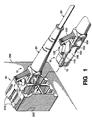
- FIG. 1 is a perspective view of a quadruplex jack receptacle 40 mounted in a rectangular aperture 250 in panel 200 and held therein by panel-locking members 410 that are molded into the top and bottom surfaces of the receptacle.
- One optical connector 10 is shown installed in one of the four cavities 460 of the receptacle, while another identical optical connector 10 is about to be installed.
- Each optical connector 10 comprises a housing 110 and a cover 100 that enclose a fiber-holding structure. Complete details regarding the specific design of such connectors are disclosed in Application Serial Number 08/520808 to Lampert et al. filed on August 30, 1995.
- optical connectors are designed to be joined together in several ways to form a duplex connector, a quadruplex connector, or an "n-plex" connector. Holes 103, 104 assist in accomplishing this goal. Details regarding the specific design of a duplex connector, for example, are disclosed in Application Serial Number 08/520809 to Lampert et al. which was also filed on August 30, 1995.
- Connector 10 includes a plug end 12 which is inserted into cavity 460 of jack receptacle 40.
- the outside surface of the connector 10 includes a latching tab 120 for securing the connector to the jack receptacle 40 in order to prevent unintended decoupling therebetween.
- Latching tab 120 is molded into the connector and includes a "living hinge" which allows it to be moved up and down in a direction that is perpendicular to a central axis of the connector.
- a trigger 130 is molded into the connector 10 and includes a living hinge which also allows it to be moved up and down in a direction which is perpendicular to the central axis of the connector.
- Latching tab 120 and trigger 130 are cantilever beams whose longitudinal axes reside in a plane that includes the central axis of the connector.
- the cantilever beams include fixed ends, and free ends that interact with each other.
- trigger 130 When trigger 130 is depressed, its free end engages the free end of latching tab 120 in order to release the connector 10 from the jack receptacle 40.
- Each illustrative optical connector 10 has a footprint (cross-section dimension) of only 4.6 by 4.6 mm, and a large number of such connectors can be grouped in a compact array.
- Cover 100 includes a reinforcement key 102 which cooperates with a mating recess 461 (see FIG. 2) within the associated jack receptacle to keep the optical connector 10 from moving when vertical-side loading is applied to the connector.
- a symmetrically positioned reinforcement key (not shown) is molded into the side of housing 110 for the same purpose.
- FIG. 2 is a perspective view of a pair of identical quadruplex jack receptacles 40-40, back to back, about to be assembled into a single adapter 400.
- Receptacle 40 includes four identical cavities 460 that are compactly arrayed and adapted to receive a plurality of optical connectors of the type shown in FIG. 1.
- Each jack receptacle 40 has a generally planar back surface 420 which includes a pair of cylindrical pins 423 projecting outwardly, a pair of cylindrical holes 421 projecting inwardly, and four openings 422 for receiving an alignment sleeve 440.
- the pins 423 each have a slightly larger diameter than the holes 421.
- each pin and holes each have a nominal diameter of 1.5 mm; but to assure a substantially permanent connection between the pins and holes, an interference of about 0.04 mm is used (i.e., each pin has a diameter which exceeds the diameter of its corresponding hole by about 0.04 mm). Nevertheless, so that the pins can be readily inserted into slightly smaller holes, each pin includes a bevel or taper 425 on its distal end.
- each of these four openings 422 comprises the bottom portion of a boss 424 (see FIG. 4) that extends into each of the four cavities 460 in the receptacle 40.
- the pair of jack receptacles 40-40 are aligned so that the pins 423 in one receptacle are positioned to mate with the holes 421 in the other receptacle, and the alignment sleeves 440 in one receptacle are positioned to mate with the openings 422 in the other receptacle.
- each pin 423 is slightly larger than its mating hole 421, the pair of receptacles can, advantageously, be press-fit together without adhesives or ultrasonic welding.
- a vertically stacked duplex connector can be assembled by joining a pair of optical connectors together, one on top of the other. A clip is attached to one side of each connector to join them together. And because it is desirable to prevent the resulting duplex connector from being inserted into receptacle 40 in certain orientations, post 462 is molded into the front of receptacle 40 so that it will interfere with the clip if the duplex connector is inserted into the wrong cavities. In other words, post 462 is used to assure correct polarization.
- the top surface 415 and bottom surface 416 of quadruplex jack receptacle 40 are identical and include a plurality of panel-locking members 410, 410.
- one panel-locking member 410 is associated with each cavity; and as will be discussed below, opening 463 between panel-locking member 410 and sidewall 465 advantageously enables a simple U-shaped molding insert to be used for molding a tab-retaining shoulder within the cavity 460.
- the panel-locking members 410, 410 comprise cantilevers whose free ends cooperate with flange 412, during insertion of receptacle 40 into an aperture in a flat panel, to capture and hold an edge of the panel therebetween.
- Quadruplex receptacle 40 is preferably molded from a thermoplastic material, such as polycarbonate, and is designed for ease of molding.
- panel-locking member 410 is a cantilever beam that is formed by molding a U-shaped opening 463 in the top surface 415 of the receptacle. This opening 463 provides direct access to a pair of tab-retaining shoulders, within the cavity of the receptacle, that are used for locking an optical connector into the receptacle. Accordingly, a simple molding insert can be used for creating the cantilever and the tab-retaining shoulder.
- a number of quadruplex jack receptacles 40 can be mounted, side by side, in a first horizontal row within a panel having an elongated rectangular aperture. No space between adjacent receptacles is required. However, when mounting a second row of quadruplex receptacles above and/or below the first row, a small vertical distance between rows is required so that a user can manually access the trigger 130 or latch 120 on an inserted optical connector 10 (shown in FIG. 1).
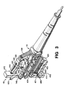
- FIG. 3 is a perspective view of an optical fiber connector 10 inserted within the quadruplex jack receptacle 40.
- a quadruplex receptacle comprises four cavities for receiving optical connectors, only two cavities are shown in cross section. Moreover, only one connector is inserted in order to illustrate certain details within the cavity interior. The top and bottom cavities are mirror images of each other.
- connector 10 is shown with its cover 100 (see FIG. 1) removed for clarity.
- the compactness of receptacle 40 is noted along with its user convenience. For example, in order to remove connector 10 from the receptacle, access to trigger 130 is required.
- the vertically stacked cavities in receptacle 40 are configured so that the trigger on one connector will be upward facing while the trigger on the other connector will be downward facing.
- Housing 110 of the connector is generally U-shaped and supports a fiber-holding structure comprising ferrule 140, base member 150, and spring 160.
- the spring 160 surrounds the back cylindrical portion of base member 150 and urges the end face of ferrule 140 from right to left, as viewed in FIG. 3.
- Ferrule 140 may be a glass, metal, ceramic or plastic cylinder having a narrow passageway (about 126 ⁇ m in diameter) through its central axis for receiving an end portion of an optical fiber.
- the ferrule has an outer diameter of about 1.25 mm and a length of about 7.0 mm.
- Receptacle 40 is secured to a panel 200 (see FIG. 1) via tapered surface 411 on its panel-locking members 410. These tapered surfaces cooperate with flange 412 to interlock the receptacle and the panel, in a snug manner, for panels having different thickness.
- Receptacle 40 is removed from the panel by squeezing the panel-locking members and pushing the receptacle forward.
- two identical receptacles 40-40 are joined by joining their back surfaces 420 together end-to-end before insertion into the panel.
- Mating portions 421, 423 are used to assure proper alignment. Nevertheless, so that the ferrules 140 within the connectors are perfectly aligned, alignment sleeves 440 (see FIG. 4) are installed in cylindrical bosses 424 before the receptacles are joined. Suitable alignment sleeves, made from metal, ceramic or even plastic material, are well known in the art and are not discussed further.
- each cavity of receptacle 40 Within each cavity of receptacle 40 are a pair of symmetrically disposed tab-retaining shoulders, each formed by a horizontal surface 431 and a vertical surface 432.
- the horizontal surface 431 interacts with projection 121 on latching tab 120 to deflect it downward (i.e., toward the central axis of the connector).
- the vertical surface 432 interacts with vertical surface 122 on projection 121 to lock optical connector 10 into the receptacle 40.
- FIG. 4 discloses an almost-symmetrical interconnection between a pair of optical fibers meeting at optical plane 70-70. And while a connector-to-connector example is shown, it is clear that the connector can be joined to any optical device. Because this drawing is nearly symmetrical, what is said regarding the left-half portion applies to the right-half portion as well.
- An end portion of each optical fiber (whose coating has been removed) is held within an axial passageway of ferrule 140, and each ferrule is held within a mating cavity of base member 150.
- a compression spring 160 surrounds the base member and urges it, and its associated ferrule, toward the other base member and ferrule.
- a pair of ferrules are axially aligned via insertion into opposite ends of the same alignment sleeve 440.
- the alignment sleeve is supported within the cylindrical passageway formed by back-to-back bosses 424, 424 which are molded into the back end of each receptacle 40.
- Connector 10 is considered a "floating" design in which the two ferrules are spring loaded and supported by alignment sleeve 440 within cylindrical boss 424 of the receptacle.
- first connector When the first connector is inserted into the left-side receptacle, its associated ferrule 140 overtravels the optical plane 70-70 between the receptacles 40, 40.
- second connector When the second connector is inserted into the right-side receptacle, and contact between the end faces of these two ferrules is made, the first ferrule is pushed backwards and the base members 150, 150 are no longer in contact with the housing 110 interior. The first ferrule continues moving backward until equilibrium is reached between the spring loading of the two ferrules provided by the compression springs.
- latching tab 120 which moves downward while being inserted into the receptacle 40, but then springs back (upwardly) after insertion is complete.
- the downward movement of the latch is caused by interference (during insertion) between projection 121 on the latch and horizontal surface 431 on the receptacle.
- vertical surface 432 on the receptacle interacts with vertical surface 122 on the projection 121 of latching tab 120 to lock the connector into the receptacle. Removal of the connector is readily accomplished by manually depressing latching tab 120 downward and pulling the connector outwardly.
- Trigger 130 advantageously extends the area which can be used for accessing the latching tab.
- panel 200 comprises a generally planar structure having a nominal thickness of about 1.65 mm (0.065 inches).
- the free end of the panel-locking member 410 includes a smooth wall 411 that is tapered at an acute angle of about 14 degrees with respect to the plane of panel 200.
- the smooth wall intersects the panel-locking member at an obtuse angle of about 104 degrees.
- the minimum and maximum distances between the tapered wall 411 and the flange 412 are about 1.5 mm and 1.8 mm respectively.
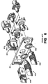
- FIG. 5 is an exploded perspective view of a wall-mounted assembly showing the interconnection among a duplex adapter 500, a carrier 300, a wall plate 100, and a pair of optical connectors 10.
- a pair of duplex jack receptacles 50 are joined together, back to back, in the same manner as was disclosed in connection with the quadruplex jack receptacles 40 shown in FIG. 2.
- the duplex jack receptacles 50 After being press-fit together, the duplex jack receptacles 50 are referred to as a duplex adapter 500, which functions to interconnect one pair of optical connectors 10 with another pair of optical connectors (not shown).
- Duplex adapter 500 is then inserted into the back side of carrier 300 until flanges 512 preclude further advancement.
- Carrier 300 also includes flanges 330 (only one flange is shown) which interact with panel locking members 510 on jack receptacle 50 to keep it joined to the carrier.
- the jack receptacle locks with flange 330 in the same way that it locks with panel 200 (see FIG. 4).
- Wall plate 100 is a generally planar structure whose dimensions are approximately 7.0 X 11.4 mm (23 ⁇ 4 X 41 ⁇ 2 inches). It is molded from a material such as Polyvinyl Chloride (PVC) and includes an aperture 115 for receiving carrier 300 which is inserted from the back side thereof. During installation, carrier 300 is pushed into aperture 115 until stop members 321 inhibit further advancement. Flexible member 323 includes a protrusion, such as wedge-shaped tab 324, for latching the carrier in place.
- the shape of aperture 115 in wall plate 100 corresponds to the shape of carrier 300, and is sized to interact with the wedge-shaped tab 324 so that the carrier will easily snap into the slots 112 and be retained therein by ledge 113. In this illustrative embodiment, ledge 113 is formed perpendicular to slot 112. Other details regarding wall plate 100 are disclosed in U.S. Patent 5,096,439.
- FIG. 6 discloses a number of known optical fiber connectors 610, 620 and 630 (each having 2.5 mm diameter ferrules) for insertion into receptacles 611, 621 and 631 respectively. Greater detail regarding these known connectors is provided in U.S. Patent 5,274,729 to King et al. Briefly, however, optical connector 610 is commonly referred to as an SC connector which fits into a jack receptacle (buildout block) 611. During assembly, the buildout block is pushed through a rectangular aperture in panel 60 where it is held in place by panel-locking member 612. This panel-locking member 612 includes a free-end portion that cooperates with flange 613 to capture panel 60 therebetween.
- SC connector jack receptacle
- receptacle 611 includes an internal latching member comprising a pair resilient catch pieces that expand into the cavity when the connector 610 is inserted. Accordingly, the disclosed receptacle 611 is larger than desired.
- Optical connectors 620 and 630 (FC-type and ST-type) also require that the user place his/her fingers onto both sides of the connector to fully rotate it during insertion and removal from their respective buildout blocks 621, 631. More importantly, these buildout blocks each require nuts 622, 632 for attachment to panel 60, and do not appear to be suitable for mass mounting in an array.
- modifications include, but are not limited to, a jack receptacle that mounts on a printed wiring board; and a jack receptacle having a different number of cavities than the number shown in the particular embodiments.
- these modifications include but are not limited to: the use of different shapes, positioning and quantity of pins/holes; the use of bonding techniques other than pins/holes to assemble the receptacles; and an adapter wherein one jack receptacle accommodates one type of optical connector while the other jack receptacle accommodates another type of optical connector.
Description
Claims (6)
- A one-piece, molded jack receptacle (40) including front and back ends, top-and bottom-side surfaces, and at least two cavities (460); each cavity having (i) a rectangular opening into the front end of the receptacle, (ii) a circular opening into the back end of the receptacle, and (iii) a U-shaped opening (463) into the top-side surface (415), said U-shaped opening forming a cantilever whose free-end portion deflects into the cavity; each cavity further having a non-movable retaining surface (432) for holding an optical connector within the cavity, said retaining surface being located directly beneath the U-shaped opening.
- The jack receptacle (40) of claim 1 wherein said receptacle is molded from thermoplastic material.
- The jack receptacle (40) of claim 2 wherein the thermoplastic material comprises polycarbonate.
- The jack receptacle (40) of claim 1 wherein the rear surface (420) is generally planar and includes at least one outwardly projecting pin (423) and at least one inwardly projecting hole (421), said pin and hole having complementary mating shapes that are positioned to interlock with an identical jack receptacle (40) when they are oriented back to back.
- The jack receptacle (40) of claim 4 wherein the pin (423) and hole (421) are cylindrically shaped, and wherein the pin has a slightly larger diameter than the hole.
- The jack receptacle (40) of claim 5 wherein said pin (423) is tapered at its distal end so that it will fit into a slightly smaller hole (421).
Applications Claiming Priority (2)
| Application Number | Priority Date | Filing Date | Title |
|---|---|---|---|
| US08/545,042 US5647043A (en) | 1995-10-12 | 1995-10-12 | Unipartite jack receptacle |
| US545042 | 1995-10-12 |
Publications (2)
| Publication Number | Publication Date |
|---|---|
| EP0768547A1 EP0768547A1 (en) | 1997-04-16 |
| EP0768547B1 true EP0768547B1 (en) | 2005-12-28 |
Family
ID=24174653
Family Applications (1)
| Application Number | Title | Priority Date | Filing Date |
|---|---|---|---|
| EP96307197A Expired - Lifetime EP0768547B1 (en) | 1995-10-12 | 1996-10-01 | Jack receptacle for an optical connector |
Country Status (8)
| Country | Link |
|---|---|
| US (1) | US5647043A (en) |
| EP (1) | EP0768547B1 (en) |
| JP (1) | JP3103773B2 (en) |
| KR (1) | KR100271076B1 (en) |
| CN (1) | CN1079953C (en) |
| AU (1) | AU708527B2 (en) |
| CA (1) | CA2184418C (en) |
| DE (1) | DE69635644T2 (en) |
Cited By (2)
| Publication number | Priority date | Publication date | Assignee | Title |
|---|---|---|---|---|
| US8221007B2 (en) | 2008-05-07 | 2012-07-17 | Huber+Suhner Ag | Plug connector having unlocking mechanism |
| DE202009019167U1 (en) | 2008-05-07 | 2017-06-06 | Huber + Suhner Ag | Connector with unlocking |
Families Citing this family (177)
| Publication number | Priority date | Publication date | Assignee | Title |
|---|---|---|---|---|
| EP0916978B1 (en) * | 1997-11-13 | 2009-04-22 | Diamond SA | Connecting device for optical drawer connexion |
| US5879197A (en) * | 1997-11-17 | 1999-03-09 | Adc Telecommunications, Inc. | Jack module |
| US6024498A (en) * | 1998-02-05 | 2000-02-15 | Lucent Technologies Inc. | Optical fiber connector assembly |
| US6102581A (en) * | 1998-06-16 | 2000-08-15 | Lucent Technologies Inc. | Optical adapter including a ferrule assembly |
| US6104856A (en) * | 1998-06-16 | 2000-08-15 | Lucent Technologies Inc. | Optical air-gap attenuator |
| US6220763B1 (en) | 1998-09-04 | 2001-04-24 | Lucent Technologies Inc. | Optical fiber buildout system |
| US6196729B1 (en) | 1998-09-04 | 2001-03-06 | Lucent Technologies Inc. | Apparatus for retaining an attenuator element |
| US6149315A (en) * | 1998-09-04 | 2000-11-21 | Lucent Technologies Inc. | Side load resistant buildout |
| US6188827B1 (en) | 1998-09-04 | 2001-02-13 | Lucent Technologies Inc. | Attenuator element for a buildout system |
| US6196731B1 (en) * | 1998-10-30 | 2001-03-06 | Lucent Technologies Inc. | Quick-connect fiber optic connector |
| US6347888B1 (en) | 1998-11-23 | 2002-02-19 | Adc Telecommunications, Inc. | Fiber optic adapter, including hybrid connector system |
| US6334792B1 (en) | 1999-01-15 | 2002-01-01 | Adc Telecommunications, Inc. | Connector including reduced crosstalk spring insert |
| AU2403500A (en) * | 1999-01-15 | 2000-08-01 | Adc Telecommunications, Incorporated | Telecommunications jack assembly |
| US6760531B1 (en) | 1999-03-01 | 2004-07-06 | Adc Telecommunications, Inc. | Optical fiber distribution frame with outside plant enclosure |
| US6293710B1 (en) | 1999-10-06 | 2001-09-25 | Lucent Technologies Inc. | Optical connector having a one-piece housing |
| US6250817B1 (en) * | 1999-10-19 | 2001-06-26 | Lucent Technologies Inc. | Device that attaches to the boot of an optical fiber simplex connector to provide the connector with anti-snagging and/or polarity identification features |
| CA2398809A1 (en) * | 2000-02-07 | 2001-08-09 | Te Huruhuru Properties Ltd. | A portable ski tow |
| US6402393B1 (en) | 2000-02-29 | 2002-06-11 | Lucent Technologies Inc. | Interconnection system for optical circuit boards |
| US7056157B2 (en) | 2000-05-26 | 2006-06-06 | Hubbell Incorporated | Adapter for data transmission systems |
| US6526210B1 (en) * | 2000-06-27 | 2003-02-25 | Cisco Technology, Inc. | Optical connector retainer panel and system |
| US6375496B1 (en) | 2000-09-18 | 2002-04-23 | Fci Americas Technology, Inc. | Double stack electrical connector with integral ground plane |
| US6588938B1 (en) | 2000-10-18 | 2003-07-08 | Fitel Usa Corp. | Optical/electrical plug connector |
| US6456768B1 (en) | 2000-10-18 | 2002-09-24 | Fitel Usa Corp. | Optical fiber cable tracing system |
| US6543941B1 (en) | 2000-10-18 | 2003-04-08 | Fitel Usa Corp. | Jack receptacle having optical and electrical ports |
| US6554484B2 (en) | 2000-12-27 | 2003-04-29 | Fitel Usa Corp. | Optical connector receptacle having switching capability |
| US6511231B2 (en) | 2000-12-27 | 2003-01-28 | Fitel Usa Corp. | Optical connector receptacle having switching capability |
| US6443627B1 (en) * | 2001-01-10 | 2002-09-03 | Fitel Usa Corp. | Duplex optical connector |
| US6478472B1 (en) | 2001-01-10 | 2002-11-12 | Fitel Usa Corp. | High-density optical connecting block |
| US6652155B2 (en) * | 2001-06-21 | 2003-11-25 | Fitel Usa Corp. | Optical connector plug |
| US6547450B2 (en) | 2001-06-27 | 2003-04-15 | Fitel Usa Corp. | Quick-release dust cap for an optical plug |
| US6554482B1 (en) * | 2001-12-20 | 2003-04-29 | Molex Incorporated | Adapter system for fiber optic connectors |
| US20030123811A1 (en) * | 2002-01-02 | 2003-07-03 | Lyon Gregory A. | Connector receptacle |
| EP1341015A1 (en) * | 2002-02-28 | 2003-09-03 | FITEL USA CORPORATION (a Delaware Corporation) | Duplex optical connector |
| US6688781B2 (en) | 2002-03-11 | 2004-02-10 | Fitel Usa Corp. | Optical connector adapter having switching capability |
| US7341698B2 (en) * | 2002-04-10 | 2008-03-11 | S.C. Johnson & Son, Inc. | Electrical evaporator including fan and louver structure |
| US6619856B1 (en) * | 2002-05-20 | 2003-09-16 | Fitel Usa Corp. | Polarization maintaining optical fiber connector adapter |
| US6814624B2 (en) * | 2002-11-22 | 2004-11-09 | Adc Telecommunications, Inc. | Telecommunications jack assembly |
| GB0228929D0 (en) * | 2002-12-11 | 2003-01-15 | R W Data Ltd | Structured cabling system and method |
| JP3800606B2 (en) | 2002-12-27 | 2006-07-26 | 日本航空電子工業株式会社 | Optical connector adapter |
| US6793537B2 (en) * | 2002-12-30 | 2004-09-21 | Methode Electronics, Inc. | Wire connector assembly and method of forming same |
| US7142764B2 (en) | 2003-03-20 | 2006-11-28 | Tyco Electronics Corporation | Optical fiber interconnect cabinets, termination modules and fiber connectivity management for the same |
| US7198409B2 (en) * | 2003-06-30 | 2007-04-03 | Adc Telecommunications, Inc. | Fiber optic connector holder and method |
| US7233731B2 (en) * | 2003-07-02 | 2007-06-19 | Adc Telecommunications, Inc. | Telecommunications connection cabinet |
| US6848833B1 (en) * | 2003-07-09 | 2005-02-01 | Molex Incorporated | Replaceable fiber optic interface module |
| US6887110B2 (en) * | 2003-07-09 | 2005-05-03 | Amphenol Corporation | High-density multi-port RJ connector |
| DE10342908A1 (en) * | 2003-09-17 | 2005-04-28 | Krone Gmbh | Housing for fiber optic connectors and procedures for laying fiber optic cables |
| US6983095B2 (en) * | 2003-11-17 | 2006-01-03 | Fiber Optic Network Solutions Corporation | Systems and methods for managing optical fibers and components within an enclosure in an optical communications network |
| US7369741B2 (en) * | 2003-11-17 | 2008-05-06 | Fiber Optics Network Solutions Corp. | Storage adapter with dust cap posts |
| US7147384B2 (en) * | 2004-03-26 | 2006-12-12 | 3M Innovative Properties Company | Small form factor optical connector with thermoplastic adhesive |
| US7218827B2 (en) | 2004-06-18 | 2007-05-15 | Adc Telecommunications, Inc. | Multi-position fiber optic connector holder and method |
| JP4017172B2 (en) * | 2004-12-28 | 2007-12-05 | 日本航空電子工業株式会社 | Optical connector device |
| US7318751B2 (en) * | 2005-01-13 | 2008-01-15 | Tyco Electronics Corporation | Die-cast adapter |
| GB2423155B (en) * | 2005-02-10 | 2009-09-09 | Agilent Technologies Inc | Keyed transceiver module |
| JP2006267649A (en) | 2005-03-24 | 2006-10-05 | Seikoh Giken Co Ltd | Optical connector |
| US7194181B2 (en) | 2005-03-31 | 2007-03-20 | Adc Telecommunications, Inc. | Adapter block including connector storage |
| US7583883B2 (en) * | 2005-07-26 | 2009-09-01 | Adc Telecommunications, Inc. | Fiber optic connector holder |
| US7623749B2 (en) | 2005-08-30 | 2009-11-24 | Adc Telecommunications, Inc. | Fiber distribution hub with modular termination blocks |
| US7816602B2 (en) | 2006-02-13 | 2010-10-19 | Adc Telecommunications, Inc. | Fiber distribution hub with outside accessible grounding terminals |
| US7720343B2 (en) | 2006-02-13 | 2010-05-18 | Adc Telecommunications, Inc. | Fiber distribution hub with swing frame and modular termination panels |
| US7760984B2 (en) | 2006-05-04 | 2010-07-20 | Adc Telecommunications, Inc. | Fiber distribution hub with swing frame and wrap-around doors |
| SG137710A1 (en) * | 2006-05-11 | 2007-12-28 | Volex Asia Pte Ltd | Positive lock connector |
| US7490996B2 (en) * | 2006-08-16 | 2009-02-17 | Sigmund Sommer | Electro-optical plug and receptacle |
| US20080050967A1 (en) * | 2006-08-24 | 2008-02-28 | Chris Poulin | Connector adapters for use in usb applications |
| US7387447B2 (en) * | 2006-09-15 | 2008-06-17 | Corning Cable Systems Llc | Secure fiber optic connector and adapter systems |
| US7689089B2 (en) * | 2006-10-11 | 2010-03-30 | Panduit Corp. | Release latch for pre-terminated cassette |
| US7496268B2 (en) * | 2006-12-13 | 2009-02-24 | Corning Cable Systems Llc | High density fiber optic hardware |
| US7822310B2 (en) * | 2007-02-28 | 2010-10-26 | Corning Cable Systems Llc | Fiber optic splice trays |
| CN201039270Y (en) * | 2007-04-03 | 2008-03-19 | 许庆仁 | A network cable interface |
| WO2009045562A1 (en) | 2007-04-13 | 2009-04-09 | Adc Telecommunications, Inc. | Optical fiber field termination kit |
| US7534050B2 (en) * | 2007-04-13 | 2009-05-19 | Adc Telecommunications, Inc. | Field terminatable fiber optic connector assembly |
| US8798427B2 (en) | 2007-09-05 | 2014-08-05 | Corning Cable Systems Llc | Fiber optic terminal assembly |
| US8229265B2 (en) * | 2007-11-21 | 2012-07-24 | Adc Telecommunications, Inc. | Fiber distribution hub with multiple configurations |
| WO2009073500A1 (en) * | 2007-11-30 | 2009-06-11 | Adc Telecommunications, Inc. | Hybrid fiber/copper connector system and method |
| US7889961B2 (en) | 2008-03-27 | 2011-02-15 | Corning Cable Systems Llc | Compact, high-density adapter module, housing assembly and frame assembly for optical fiber telecommunications |
| WO2009132168A2 (en) * | 2008-04-25 | 2009-10-29 | 3M Innovative Properties Company | Field terminable lc format optical connector with splice element |
| US8202012B2 (en) * | 2008-07-31 | 2012-06-19 | Hewlett-Packard Development Company, L.P. | Electro-optical connector and methods for aligning |
| CN103543501B (en) * | 2008-08-27 | 2016-08-24 | Adc电信公司 | There is the fiber adapter of the ferrule alignment structure of global formation |
| US8452148B2 (en) | 2008-08-29 | 2013-05-28 | Corning Cable Systems Llc | Independently translatable modules and fiber optic equipment trays in fiber optic equipment |
| US11294135B2 (en) | 2008-08-29 | 2022-04-05 | Corning Optical Communications LLC | High density and bandwidth fiber optic apparatuses and related equipment and methods |
| EP2344915A4 (en) | 2008-10-09 | 2015-01-21 | Corning Cable Sys Llc | Fiber optic terminal having adapter panel supporting both input and output fibers from an optical splitter |
| US8879882B2 (en) | 2008-10-27 | 2014-11-04 | Corning Cable Systems Llc | Variably configurable and modular local convergence point |
| US8417074B2 (en) | 2008-11-21 | 2013-04-09 | Adc Telecommunications, Inc. | Fiber optic telecommunications module |
| CH700064A1 (en) | 2008-12-01 | 2010-06-15 | Reichle & De Massari Fa | Duplex adapter and protection device for an optical connector. |
| ATE534049T1 (en) | 2009-02-24 | 2011-12-15 | Ccs Technology Inc | CABLE HOLDING DEVICE OR ARRANGEMENT FOR USE WITH A CABLE |
| JP2010211024A (en) * | 2009-03-11 | 2010-09-24 | Fujitsu Ltd | Lc adapter |
| EP2237091A1 (en) | 2009-03-31 | 2010-10-06 | Corning Cable Systems LLC | Removably mountable fiber optic terminal |
| US8699838B2 (en) | 2009-05-14 | 2014-04-15 | Ccs Technology, Inc. | Fiber optic furcation module |
| US8538226B2 (en) | 2009-05-21 | 2013-09-17 | Corning Cable Systems Llc | Fiber optic equipment guides and rails configured with stopping position(s), and related equipment and methods |
| US9075216B2 (en) | 2009-05-21 | 2015-07-07 | Corning Cable Systems Llc | Fiber optic housings configured to accommodate fiber optic modules/cassettes and fiber optic panels, and related components and methods |
| US8283802B2 (en) | 2009-06-11 | 2012-10-09 | American Power Conversion Corporation | Dual column gang outlets for minimizing installation space |
| ES2793952T3 (en) | 2009-06-19 | 2020-11-17 | Corning Optical Communications LLC | High Density and Bandwidth Fiber Optic Apparatus |
| JP2012530943A (en) | 2009-06-19 | 2012-12-06 | コーニング ケーブル システムズ リミテッド ライアビリティ カンパニー | High fiber optic cable packaging density equipment |
| US8712206B2 (en) | 2009-06-19 | 2014-04-29 | Corning Cable Systems Llc | High-density fiber optic modules and module housings and related equipment |
| US8467651B2 (en) | 2009-09-30 | 2013-06-18 | Ccs Technology Inc. | Fiber optic terminals configured to dispose a fiber optic connection panel(s) within an optical fiber perimeter and related methods |
| US9261654B2 (en) | 2009-10-13 | 2016-02-16 | Leviton Manufacturing Co., Inc. | Fiber optic adapter plates with integrated fiber optic adapters |
| US20110129186A1 (en) * | 2009-11-30 | 2011-06-02 | Lewallen C Paul | Fiber Optic Module Assembly and Associated Methods |
| US8625950B2 (en) | 2009-12-18 | 2014-01-07 | Corning Cable Systems Llc | Rotary locking apparatus for fiber optic equipment trays and related methods |
| US8992099B2 (en) | 2010-02-04 | 2015-03-31 | Corning Cable Systems Llc | Optical interface cards, assemblies, and related methods, suited for installation and use in antenna system equipment |
| US8406597B2 (en) * | 2010-02-16 | 2013-03-26 | Commscope, Inc. Of North Carolina | Intelligent fiber optic adapter mounting structures that receive and correctly position multiple types of fiber optic adapters and related adapter collars and bulkheads |
| EP2542930A1 (en) | 2010-03-02 | 2013-01-09 | Tyco Electronics Services GmbH | Fibre-optic telecommunication module |
| US9547144B2 (en) | 2010-03-16 | 2017-01-17 | Corning Optical Communications LLC | Fiber optic distribution network for multiple dwelling units |
| US8913866B2 (en) | 2010-03-26 | 2014-12-16 | Corning Cable Systems Llc | Movable adapter panel |
| EP2558895B1 (en) | 2010-04-16 | 2019-04-17 | Corning Optical Communications LLC | Sealing and strain relief device for data cables |
| US8792767B2 (en) | 2010-04-16 | 2014-07-29 | Ccs Technology, Inc. | Distribution device |
| US8025514B1 (en) | 2010-04-23 | 2011-09-27 | Leviton Manufacturing Co., Inc. | Shroud to prevent manipulation of a release mechanism of a plug |
| EP2381284B1 (en) | 2010-04-23 | 2014-12-31 | CCS Technology Inc. | Under floor fiber optic distribution device |
| US8038456B1 (en) | 2010-04-23 | 2011-10-18 | Leviton Manufacturing Co., Inc | Tamper prevention system having a shroud to partially cover a release mechanism |
| US9720195B2 (en) | 2010-04-30 | 2017-08-01 | Corning Optical Communications LLC | Apparatuses and related components and methods for attachment and release of fiber optic housings to and from an equipment rack |
| US9632270B2 (en) | 2010-04-30 | 2017-04-25 | Corning Optical Communications LLC | Fiber optic housings configured for tool-less assembly, and related components and methods |
| US8660397B2 (en) | 2010-04-30 | 2014-02-25 | Corning Cable Systems Llc | Multi-layer module |
| US8879881B2 (en) | 2010-04-30 | 2014-11-04 | Corning Cable Systems Llc | Rotatable routing guide and assembly |
| US9075217B2 (en) | 2010-04-30 | 2015-07-07 | Corning Cable Systems Llc | Apparatuses and related components and methods for expanding capacity of fiber optic housings |
| US9519118B2 (en) | 2010-04-30 | 2016-12-13 | Corning Optical Communications LLC | Removable fiber management sections for fiber optic housings, and related components and methods |
| US8705926B2 (en) | 2010-04-30 | 2014-04-22 | Corning Optical Communications LLC | Fiber optic housings having a removable top, and related components and methods |
| US8718436B2 (en) | 2010-08-30 | 2014-05-06 | Corning Cable Systems Llc | Methods, apparatuses for providing secure fiber optic connections |
| CN103430072B (en) | 2010-10-19 | 2018-08-10 | 康宁光缆系统有限责任公司 | For the transformation box in the fiber distribution network of multitenant unit |
| US9279951B2 (en) | 2010-10-27 | 2016-03-08 | Corning Cable Systems Llc | Fiber optic module for limited space applications having a partially sealed module sub-assembly |
| US8662760B2 (en) | 2010-10-29 | 2014-03-04 | Corning Cable Systems Llc | Fiber optic connector employing optical fiber guide member |
| CN203759315U (en) | 2010-11-30 | 2014-08-06 | 康宁光缆系统有限责任公司 | Optical fiber device |
| WO2012075121A2 (en) | 2010-11-30 | 2012-06-07 | Adc Telecommunications, Inc. | Lc connector and method of assembly |
| WO2012106510A2 (en) | 2011-02-02 | 2012-08-09 | Corning Cable Systems Llc | Dense fiber optic connector assemblies and related connectors and cables suitable for establishing optical connections for optical backplanes in equipment racks |
| US8636425B2 (en) | 2011-03-15 | 2014-01-28 | Adc Telecommunications, Inc. | Fiber optic connector |
| US9008485B2 (en) | 2011-05-09 | 2015-04-14 | Corning Cable Systems Llc | Attachment mechanisms employed to attach a rear housing section to a fiber optic housing, and related assemblies and methods |
| CN202995082U (en) | 2011-06-27 | 2013-06-12 | 3M创新有限公司 | Optical fiber connector for terminating optical fibers |
| CN103649805B (en) | 2011-06-30 | 2017-03-15 | 康宁光电通信有限责任公司 | Fiber plant assembly of shell using non-U-width size and associated method |
| US8953924B2 (en) | 2011-09-02 | 2015-02-10 | Corning Cable Systems Llc | Removable strain relief brackets for securing fiber optic cables and/or optical fibers to fiber optic equipment, and related assemblies and methods |
| US9417418B2 (en) | 2011-09-12 | 2016-08-16 | Commscope Technologies Llc | Flexible lensed optical interconnect device for signal distribution |
| CN103917904A (en) | 2011-10-07 | 2014-07-09 | Adc电信公司 | Fiber optic cassette, system, and method |
| US9038832B2 (en) | 2011-11-30 | 2015-05-26 | Corning Cable Systems Llc | Adapter panel support assembly |
| US9219546B2 (en) | 2011-12-12 | 2015-12-22 | Corning Optical Communications LLC | Extremely high frequency (EHF) distributed antenna systems, and related components and methods |
| US9075203B2 (en) | 2012-01-17 | 2015-07-07 | Adc Telecommunications, Inc. | Fiber optic adapter block |
| CN104364686B (en) | 2012-02-07 | 2016-11-16 | 泰科电子瑞侃有限公司 | Cable termination assembly and method for adapter |
| US10110307B2 (en) | 2012-03-02 | 2018-10-23 | Corning Optical Communications LLC | Optical network units (ONUs) for high bandwidth connectivity, and related components and methods |
| US9176285B2 (en) | 2012-05-03 | 2015-11-03 | Adc Telecommunications, Inc. | Fiber optic connector |
| US9004778B2 (en) | 2012-06-29 | 2015-04-14 | Corning Cable Systems Llc | Indexable optical fiber connectors and optical fiber connector arrays |
| US9250409B2 (en) | 2012-07-02 | 2016-02-02 | Corning Cable Systems Llc | Fiber-optic-module trays and drawers for fiber-optic equipment |
| DE102012107556A1 (en) * | 2012-08-17 | 2014-02-20 | HARTING Electronics GmbH | Device and method for reversible, mechanical fixation and electrical contacting of electrical conductors |
| US9049500B2 (en) | 2012-08-31 | 2015-06-02 | Corning Cable Systems Llc | Fiber optic terminals, systems, and methods for network service management |
| US20140072263A1 (en) * | 2012-09-10 | 2014-03-13 | Alliance Fiber Optic Products, Inc. | Optical fiber adapter having vertical wings |
| US9042702B2 (en) | 2012-09-18 | 2015-05-26 | Corning Cable Systems Llc | Platforms and systems for fiber optic cable attachment |
| US9146362B2 (en) | 2012-09-21 | 2015-09-29 | Adc Telecommunications, Inc. | Insertion and removal tool for a fiber optic ferrule alignment sleeve |
| US9488788B2 (en) | 2012-09-28 | 2016-11-08 | Commscope Technologies Llc | Fiber optic cassette |
| US9146374B2 (en) | 2012-09-28 | 2015-09-29 | Adc Telecommunications, Inc. | Rapid deployment packaging for optical fiber |
| US9223094B2 (en) | 2012-10-05 | 2015-12-29 | Tyco Electronics Nederland Bv | Flexible optical circuit, cassettes, and methods |
| US8909019B2 (en) | 2012-10-11 | 2014-12-09 | Ccs Technology, Inc. | System comprising a plurality of distribution devices and distribution device |
| EP2725397B1 (en) | 2012-10-26 | 2015-07-29 | CCS Technology, Inc. | Fiber optic management unit and fiber optic distribution device |
| US9086546B2 (en) * | 2012-11-29 | 2015-07-21 | Corning Cable Systems Llc | Connector systems having receptacle assembly and plug assembly |
| US8985862B2 (en) | 2013-02-28 | 2015-03-24 | Corning Cable Systems Llc | High-density multi-fiber adapter housings |
| CN104035162B (en) * | 2013-03-08 | 2015-11-11 | 东侑光电股份有限公司 | Fiber adapter |
| US9435975B2 (en) | 2013-03-15 | 2016-09-06 | Commscope Technologies Llc | Modular high density telecommunications frame and chassis system |
| US10326229B2 (en) * | 2013-03-15 | 2019-06-18 | Knxid, Llc | Termination identification device and system |
| CN105359020A (en) * | 2013-05-21 | 2016-02-24 | 康宁光电通信有限责任公司 | Gang fiber adaptor and assemblies thereof |
| CN103480117B (en) * | 2013-09-17 | 2017-02-08 | 山东渤海体育器材有限公司 | Spliced box horse |
| WO2015089241A1 (en) * | 2013-12-10 | 2015-06-18 | Volex Plc | Non-standard slim lock connector system |
| US9851524B2 (en) | 2014-01-28 | 2017-12-26 | Commscope Technologies Llc | Slidable fiber optic connection module with cable slack management |
| US9494758B2 (en) | 2014-04-03 | 2016-11-15 | Commscope Technologies Llc | Fiber optic distribution system |
| CN105093423A (en) * | 2014-05-12 | 2015-11-25 | 昆山迎翔光电科技有限公司 | LC type fiber connector |
| US9690065B2 (en) | 2014-09-12 | 2017-06-27 | Panduit Corp. | High density fiber enclosure and method |
| US10222557B2 (en) | 2014-09-29 | 2019-03-05 | Us Conec, Ltd. | Spring push with integral trigger |
| KR101669895B1 (en) * | 2015-01-21 | 2016-11-01 | 주식회사 제이티 | Separable Connector and Coupling kit |
| GB2538089B (en) * | 2015-05-06 | 2019-06-19 | Fibrefab Ltd | Fibre optic cable assembly |
| US10302874B2 (en) | 2015-05-15 | 2019-05-28 | Commscope Telecommunications (Shanghai) Co., Ltd. | Alignment sleeve assembly and fiber optic adapter |
| DE102016002423B3 (en) * | 2016-03-02 | 2017-06-01 | Langmatz Gmbh | Adapter for patch cassettes or patch fields |
| CN107329210B (en) | 2016-04-19 | 2021-03-09 | 西蒙公司 | Communication connector mounting clip |
| US10215944B2 (en) | 2016-06-30 | 2019-02-26 | Panduit Corp. | Modular fiber optic tray |
| FR3053848B1 (en) * | 2016-07-07 | 2018-07-06 | Radiall | SYSTEM FOR CONNECTING A PLURALITY OF PLUG SHEETS TO A MONOBLOCK ASSEMBLY OF AN ELECTRONIC EQUIPMENT BOX PANEL AND A PLURALITY OF CONNECTOR PLUGS |
| US9823428B1 (en) | 2017-01-25 | 2017-11-21 | Fluke Corporation | Optical connector and duplex connector assembly |
| US10120140B2 (en) | 2017-01-25 | 2018-11-06 | Fluke Corporation | Connector and duplex connector assembly |
| US10871619B2 (en) * | 2017-01-30 | 2020-12-22 | Senko Advanced Components, Inc. | Cassette assembly for a plural of fiber optic receptacles |
| US11409068B2 (en) | 2017-10-02 | 2022-08-09 | Commscope Technologies Llc | Fiber optic circuit and preparation method |
| EP3540867A1 (en) * | 2018-03-16 | 2019-09-18 | Connecteurs Electriques Deutsch | Connector housing and adapter |
| US11409054B2 (en) * | 2018-05-11 | 2022-08-09 | Us Conec Ltd. | Method and apparatus for assembling uniboot fiber optic connectors |
| DE102018113365A1 (en) * | 2018-06-05 | 2019-12-05 | Rosenberger Hochfrequenztechnik Gmbh & Co. Kg | Modular connector system |
| US11454767B2 (en) * | 2018-10-10 | 2022-09-27 | Senko Advanced Components, Inc. | Multi-polarity fiber optic connector having a duplex cable boot assembly |
| US11181696B2 (en) * | 2019-02-22 | 2021-11-23 | Senko Advanced Components, Inc. | Adapter assembly having a return spring with a push-pull tab |
| US11226452B2 (en) | 2020-05-11 | 2022-01-18 | Google Llc | Dual polarity optical fiber adaptor with protruding tab and patch panel |
| CN115437075B (en) * | 2022-09-01 | 2023-07-25 | 烽火通信科技股份有限公司 | Optical fiber connection box and optical fiber connection box assembly |
Citations (1)
| Publication number | Priority date | Publication date | Assignee | Title |
|---|---|---|---|---|
| US5418875A (en) * | 1992-09-04 | 1995-05-23 | Honda Tsushin Kogyo Co., Ltd. | Adapter for optical connector having float-type sleeve holder and panel fitting for mounting the same |
Family Cites Families (10)
| Publication number | Priority date | Publication date | Assignee | Title |
|---|---|---|---|---|
| US4341439A (en) * | 1979-10-04 | 1982-07-27 | Trw Inc. | Optical fiber connector and method of making same |
| JPS57196208A (en) * | 1981-05-29 | 1982-12-02 | Hitachi Ltd | Plastic composite containing filler for molding optical connector or the like and precise molded goods using this composite |
| US4611887A (en) * | 1983-02-24 | 1986-09-16 | Amp Incorporated | Fiber optic connector assembly and wall outlet thereof |
| US4687291A (en) * | 1984-06-08 | 1987-08-18 | Amp Incorporated | Duplex electro-fiber connector assembly |
| JPH06100698B2 (en) * | 1984-06-08 | 1994-12-12 | アンプ・インコ−ポレ−テッド | Optical fiber connector assembly |
| JPH077139B2 (en) * | 1985-12-24 | 1995-01-30 | 日本電信電話株式会社 | Floating holder type optical connector |
| US5123071A (en) * | 1990-03-09 | 1992-06-16 | Amp Incorporated | Overconnector assembly for a pair of push-pull coupling type optical fiber connectors |
| FR2663755B1 (en) * | 1990-06-21 | 1992-09-18 | Radiall Sa | CONNECTOR FOR OPTICAL FIBERS WITH QUICK LOCKING AND UNLOCKING. |
| US5096439A (en) * | 1991-08-28 | 1992-03-17 | At&T Bell Laboratories | Wall plate having jack-release slots |
| US5274729A (en) * | 1992-07-30 | 1993-12-28 | At&T Bell Laboratories | Universal optical fiber buildout system |
-
1995
- 1995-10-12 US US08/545,042 patent/US5647043A/en not_active Expired - Lifetime
-
1996
- 1996-08-29 CA CA002184418A patent/CA2184418C/en not_active Expired - Lifetime
- 1996-09-09 JP JP08237433A patent/JP3103773B2/en not_active Expired - Lifetime
- 1996-10-01 DE DE69635644T patent/DE69635644T2/en not_active Expired - Lifetime
- 1996-10-01 EP EP96307197A patent/EP0768547B1/en not_active Expired - Lifetime
- 1996-10-11 KR KR1019960046109A patent/KR100271076B1/en not_active IP Right Cessation
- 1996-10-11 CN CN96122843A patent/CN1079953C/en not_active Expired - Lifetime
- 1996-10-11 AU AU68177/96A patent/AU708527B2/en not_active Expired
Patent Citations (1)
| Publication number | Priority date | Publication date | Assignee | Title |
|---|---|---|---|---|
| US5418875A (en) * | 1992-09-04 | 1995-05-23 | Honda Tsushin Kogyo Co., Ltd. | Adapter for optical connector having float-type sleeve holder and panel fitting for mounting the same |
Cited By (4)
| Publication number | Priority date | Publication date | Assignee | Title |
|---|---|---|---|---|
| US8221007B2 (en) | 2008-05-07 | 2012-07-17 | Huber+Suhner Ag | Plug connector having unlocking mechanism |
| EP2664951A1 (en) | 2008-05-07 | 2013-11-20 | Huber + Suhner Ag | Plug connector having unlocking mechanism |
| EP3101456A1 (en) | 2008-05-07 | 2016-12-07 | Huber + Suhner Ag | Plug connector having unlocking mechanism |
| DE202009019167U1 (en) | 2008-05-07 | 2017-06-06 | Huber + Suhner Ag | Connector with unlocking |
Also Published As
| Publication number | Publication date |
|---|---|
| AU708527B2 (en) | 1999-08-05 |
| KR970022382A (en) | 1997-05-28 |
| AU6817796A (en) | 1997-04-17 |
| CN1079953C (en) | 2002-02-27 |
| DE69635644D1 (en) | 2006-02-02 |
| DE69635644T2 (en) | 2006-08-10 |
| CA2184418A1 (en) | 1997-04-13 |
| US5647043A (en) | 1997-07-08 |
| CA2184418C (en) | 2002-06-11 |
| JP3103773B2 (en) | 2000-10-30 |
| JPH09113750A (en) | 1997-05-02 |
| CN1154483A (en) | 1997-07-16 |
| EP0768547A1 (en) | 1997-04-16 |
| KR100271076B1 (en) | 2000-11-01 |
Similar Documents
| Publication | Publication Date | Title |
|---|---|---|
| EP0768547B1 (en) | Jack receptacle for an optical connector | |
| US5579425A (en) | Anti-snag duplex connector | |
| CA2198522C (en) | Optical connector with immovable ferrule | |
| US11822133B2 (en) | Ultra-small form factor optical connector and adapter | |
| US5774611A (en) | Optical receptacle and housing therefor | |
| US6478472B1 (en) | High-density optical connecting block | |
| US6443627B1 (en) | Duplex optical connector | |
| US5987203A (en) | Distribution module for optical couplings | |
| CA2332780C (en) | Interconnection system for optical circuit boards | |
| US10746938B2 (en) | Fiber optic connectors | |
| US11828989B2 (en) | Fiber optic connectors, fiber optic adapters and related fiber optic connection systems | |
| KR20210020868A (en) | Tiny form factor optical connectors and adapters | |
| CN112639562A (en) | Indexing cable assembly and housing for use therewith | |
| US20220171135A1 (en) | Fiber optic adapter holder; assembly; and method | |
| WO2006029299A2 (en) | Optical connector system including reduced-size mt-style ferrule | |
| JP2003255186A (en) | Double optical connector | |
| US20210080657A1 (en) | Fiber optic connector for hardware interiors and method of using same | |
| EP1341015A1 (en) | Duplex optical connector | |
| JP3524331B2 (en) | Multiple receptacle device | |
| JP4100544B2 (en) | High density optical connection block | |
| WO2022081547A1 (en) | Multi-fiber connector system | |
| EP1341014A1 (en) | High-density optical connecting block | |
| King et al. | A modular adapter system for fiber optics |
Legal Events
| Date | Code | Title | Description |
|---|---|---|---|
| PUAI | Public reference made under article 153(3) epc to a published international application that has entered the european phase |
Free format text: ORIGINAL CODE: 0009012 |
|
| AK | Designated contracting states |
Kind code of ref document: A1 Designated state(s): DE FR GB IT |
|
| 17P | Request for examination filed |
Effective date: 19971003 |
|
| 17Q | First examination report despatched |
Effective date: 20030414 |
|
| GRAP | Despatch of communication of intention to grant a patent |
Free format text: ORIGINAL CODE: EPIDOSNIGR1 |
|
| GRAS | Grant fee paid |
Free format text: ORIGINAL CODE: EPIDOSNIGR3 |
|
| GRAA | (expected) grant |
Free format text: ORIGINAL CODE: 0009210 |
|
| AK | Designated contracting states |
Kind code of ref document: B1 Designated state(s): DE FR GB IT |
|
| PG25 | Lapsed in a contracting state [announced via postgrant information from national office to epo] |
Ref country code: IT Free format text: LAPSE BECAUSE OF FAILURE TO SUBMIT A TRANSLATION OF THE DESCRIPTION OR TO PAY THE FEE WITHIN THE PRESCRIBED TIME-LIMIT;WARNING: LAPSES OF ITALIAN PATENTS WITH EFFECTIVE DATE BEFORE 2007 MAY HAVE OCCURRED AT ANY TIME BEFORE 2007. THE CORRECT EFFECTIVE DATE MAY BE DIFFERENT FROM THE ONE RECORDED. Effective date: 20051228 |
|
| REG | Reference to a national code |
Ref country code: GB Ref legal event code: FG4D |
|
| REF | Corresponds to: |
Ref document number: 69635644 Country of ref document: DE Date of ref document: 20060202 Kind code of ref document: P |
|
| ET | Fr: translation filed | ||
| PLBE | No opposition filed within time limit |
Free format text: ORIGINAL CODE: 0009261 |
|
| STAA | Information on the status of an ep patent application or granted ep patent |
Free format text: STATUS: NO OPPOSITION FILED WITHIN TIME LIMIT |
|
| 26N | No opposition filed |
Effective date: 20060929 |
|
| REG | Reference to a national code |
Ref country code: FR Ref legal event code: ST Effective date: 20080630 |
|
| REG | Reference to a national code |
Ref country code: FR Ref legal event code: D3 |
|
| REG | Reference to a national code |
Ref country code: FR Ref legal event code: PLFP Year of fee payment: 20 |
|
| PGFP | Annual fee paid to national office [announced via postgrant information from national office to epo] |
Ref country code: IT Payment date: 20160129 Year of fee payment: 20 Ref country code: DE Payment date: 20160128 Year of fee payment: 20 |
|
| PGFP | Annual fee paid to national office [announced via postgrant information from national office to epo] |
Ref country code: GB Payment date: 20160127 Year of fee payment: 20 Ref country code: FR Payment date: 20160127 Year of fee payment: 20 |
|
| REG | Reference to a national code |
Ref country code: DE Ref legal event code: R071 Ref document number: 69635644 Country of ref document: DE |
|
| REG | Reference to a national code |
Ref country code: GB Ref legal event code: PE20 Expiry date: 20160930 |
|
| PG25 | Lapsed in a contracting state [announced via postgrant information from national office to epo] |
Ref country code: GB Free format text: LAPSE BECAUSE OF EXPIRATION OF PROTECTION Effective date: 20160930 |